EP1637251B1 - Spring manufacturing machine comprising a wire feeder driving mechanism - Google Patents
Spring manufacturing machine comprising a wire feeder driving mechanism Download PDFInfo
- Publication number
- EP1637251B1 EP1637251B1 EP04022427A EP04022427A EP1637251B1 EP 1637251 B1 EP1637251 B1 EP 1637251B1 EP 04022427 A EP04022427 A EP 04022427A EP 04022427 A EP04022427 A EP 04022427A EP 1637251 B1 EP1637251 B1 EP 1637251B1
- Authority
- EP
- European Patent Office
- Prior art keywords
- driving device
- manufacturing machine
- spring manufacturing
- axial driving
- wire feeder
- Prior art date
- Legal status (The legal status is an assumption and is not a legal conclusion. Google has not performed a legal analysis and makes no representation as to the accuracy of the status listed.)
- Not-in-force
Links
Images


Classifications
-
- B—PERFORMING OPERATIONS; TRANSPORTING
- B21—MECHANICAL METAL-WORKING WITHOUT ESSENTIALLY REMOVING MATERIAL; PUNCHING METAL
- B21F—WORKING OR PROCESSING OF METAL WIRE
- B21F35/00—Making springs from wire
-
- B—PERFORMING OPERATIONS; TRANSPORTING
- B21—MECHANICAL METAL-WORKING WITHOUT ESSENTIALLY REMOVING MATERIAL; PUNCHING METAL
- B21F—WORKING OR PROCESSING OF METAL WIRE
- B21F23/00—Feeding wire in wire-working machines or apparatus
Definitions
- the present invention relates in general to a spring manufacturing machine, and more particularly, to a wire feeder driving mechanism which enables a spring manufacturing machine to simplify the actuating mechanism of its tool seat and thereby significantly cuts down the labor hours consumed for adjustment of the tool set of the spring manufacturing machine.
- the present invention enhances the easiness and the convenience of the operation of the spring manufacturing machine.
- a spring manufacturing machine allowing a two-dimensional movement of the wire feeding church is known from EP-0 804 978 .
- springs are widely utilized in the shock absorbing or shock reducing, such as for automobiles, toys, electric appliances, switches, medical utilities, and so on, they have become an indispensable part of electric or mechanical equipments.
- the demand of spring shape becomes more and more versatile; it therefore cannot be satisfied by a conventional spring manufacturing machine. Accordingly, to develop a next generation product to satisfy the strong demand of the market is an important issue for persons skilled in the spring manufacturing machine.
- a conventional spring manufacturing machine includes a machine base 10a and a work table 20a.
- the machine base 10a is secured thereon a wire feeder 11a which has a wire feeding chuck 12a at the front end thereof.
- the feeding chuck 12a is able to output the metal wire which will be formed into a spring.
- the work table 20a has a feeder hole 21a formed in the middle thereof which is able to receive the feeding chuck 12a.
- a plurality of tool seats 22a are installed on the work table 20a.
- Each tool seat 22a includes a driving rod 221 a, a rail cam 222a, and a tool set 223a. By utilizing the driving rod 221a and the rail cam 222a, the tool set 223a is able to perform a linear or a curve motion for bending, winding, or cutting process of the metal wire.
- the conventional spring manufacturing machine has several radical problems.
- Third, to perform a curve motion of the tool set 223a it is conventional to further install a complicated or adjustable driving member.
- This auxiliary driving member not only raises the material and manufacture cost but also increases the difficulty of assembling and maintenance. Fourth, when various manufacture industries' demand for spring configuration becomes more and more complicated, the tool seats 22a installed on the work table 20a for convention are not sufficient. It is unable to satisfy modem manufacture industries' demand.
- the present invention provides a wire feeder driving mechanism for a spring manufacturing machine, which enables a wire feeder to perform a two-dimensional or a three-dimensional motion through installation of a three-dimensional driving device.
- This invention successfully enables a spring manufacturing machine to simplify the actuating mechanism of its tool seat and thereby significantly cuts down the labor hours consumed for adjustment of the tool set of a spring manufacturing machine.
- the present invention enhances the easiness and the convenience of the operation and maintenance of a spring manufacturing machine.
- This wire feeder driving mechanism includes a wire feeder 10, a first axial driving device 20, and a second axial driving device 30.
- a three dimensional Cartesian coordinate system is further designated in some figures.
- the wire feeder 10 includes a feeding box 11, a reeling motor 15, a feeding motor 16, a feeding chuck 18, and a spindle rotating motor 19.
- the feeding box 11 has a fixing platform 12 installed at one side thereof.
- a shaft mount 13 extends from the fixing platform 12.
- a shaft hole 14 is formed at the center of the shaft mount 13.
- the reeling motor 15 and the feeding motor 16 are connected to the rear of the feeding box 11.
- the reeling motor 15 rotates a metal wire reel in order to supply the wire feeder 10 with a metal wire.
- the feeding motor 16 feeds forward the metal wire through the rotating of a feed roller set 17.
- the feeding chuck 18 has a central hole which is utilized to receive and forward the metal wire.
- the spindle rotating motor 19 is able to drive and rotate the feeding chuck 18, which facilitates processing the metal wire at different angles.
- the first axial driving device 20 can be disposed parallel with the X axis, the Y axis, or the Z axis of the spring manufacturing machine.
- the first driving device 20 is in figure 2 parallel with the Y axis of the spring manufacturing machine.
- the first axial driving device 20 includes a Y axis base body 21, a servo motor 22, a Y axis lead screw 23, and a flange mount 24.
- the Y axis base body 21 is constructed of a horizontal board 211 and a vertical frame 212, with a L-shaped configuration.
- a shaft mount 213 is formed at and extends from the middle of one side of the horizontal board 211.
- a shaft hole 214 is bored from the center of the shaft mount 213.
- the vertical frame 212 has parallel slide rails 215 installed at the both sides thereof.
- a plurality of slide blocks 216 are installed onto each slide rail 215.
- the slide block 216 is connected to the fixing platform 12 of the wire feeder 10.
- a fixed brace 217 is formed at and extends from the top of the vertical frame 212.
- the fixed brace 217 is utilized to install the servo motor 22.
- the servo motor 22 has a motor shaft which is oriented toward and coupled to the Y axis lead screw 23 through a shaft coupler or other mechanical elements.
- the Y axis lead screw 23 is oriented parallel with the moving direction of the slide rail 215.
- the flange mount 24 is screwed onto the Y axis lead screw 23 with one end thereof received by the shaft hole 14 of the feeding box 11 while the other end thereof secured on the shaft mount 13 of the feeding box 11 through bolts and nuts or other means.
- the second axial driving device 30 can be disposed parallel with the X axis, the Y axis, or the Z axis of the spring manufacturing machine. In figure 2 the second driving device 30 is parallel with the X axis of the spring manufacturing machine. The moving direction of the second axial driving device 30 is thereby perpendicular to that of the first axial driving device 20.
- the second axial driving device 30 is secured on the spring manufacturing machine through bolts and nuts or other mechanical elements, and further assembled with the first axial driving device 20 to enable the wire feeder 10 to perform a two dimensional planar movement.
- the second axial driving device 30 includes a X axis base body 31, a servo motor 32, a X axis lead screw 33, and a flange mount 34.
- the X axis base body 31 is secured on the spring manufacturing machine through a plurality of bolts and nuts or other means.
- a shaft mount 311 is formed at and extends from the middle of one side of X axis base body 31.
- a shaft hole 312 is bored from the center of the shaft mount 311.
- the X axis base body 31 has parallel slide rails 313 installed thereon which are perpendicular with the direction of the shaft hole 312.
- a plurality of slide blocks 314 are installed onto each slide rail 313.
- the horizontal board 211 of the Y axis base body 21 is placed onto and connected with the slide blocks 314.
- a fixed brace 315 is formed at and extends from one side of the X axis base body 31.
- the fixed brace 315 is utilized to install the servo motor 32.
- the servo motor 32 has a motor shaft which is oriented toward and coupled to the X axis lead screw 33 through a shaft coupler and other mechanical elements.
- the X axis lead screw 33 is disposed parallel with the moving direction of the slide rail 313.
- the flange mount 34 is screwed onto the X axis lead screw 33 with one end thereof received by the shaft hole 214 of the Y axis base body 21 while the other end thereof secured on the shaft mount 213 of the Y axis base body 21 through bolts or other means.
- an embodiment of the present invention further includes a third axial driving device 40 which is installed beneath the second axial driving device 30.
- the third axial driving device 40 can be disposed parallel with the X axis, the Y axis, or the Z axis of the spring manufacturing machine.
- the third axial driving device 40 is parallel with the Z axis of the spring manufacturing machine.
- the moving direction of the third axial driving device 40 is thereby perpendicular to those of the first and the second axial driving device 20, 30.
- the third axial driving device 40 is secured on the spring manufacturing machine through bolts and nuts or other means.
- the third axial driving device 40 is further assembled with the first and the second axial driving device 20, 30 to enable the wire feeder 10 to perform a three-dimensional movement.
- the third axial driving device 40 includes a Z axis base body 41, a servo motor 42, a Z axis lead screw 43, and a flange mount 44.
- the Z axis base body 41 has a plurality of through holes 411 formed thereon which are able to be inserted through by a plurality of bolts to secure the Z axis base body 41 onto the spring manufacturing machine, respectively.
- the Z axis base body 41 has parallel slide rails 412 installed on the top thereof. A plurality of slide blocks 413 are installed onto each slide rail 412.
- the X axis base body 31 is placed onto and connected with the slide blocks 413. Further, a fixed brace 414 is formed at and extends from one side of the Z axis base body 41. The fixed brace 414 is utilized to install the servo motor 42.
- the servo motor 42 has a motor shaft which is oriented toward and coupled to the Z axis lead screw 43 through a shaft coupler and other mechanical elements.
- the Z axis lead screw 43 is oriented parallel with the moving direction of the slide rail 412.
- the flange mount 44 is screwed onto the Z axis lead screw 43 with one end thereof received by the shaft hole 312 of the X axis base body 31 while the other end thereof secured on the shaft mount 311 of the X axis base body 31 through bolts or other means.
- a wire feeder 10 and a work table 52 are assembled onto the machine base 51 of the spring manufacturing machine 5.
- the spring manufacturing machine 5 has the machine base 51 installed parallel with the Z axis thereof which is perpendicular to the X-Y plane.
- the machine base 51 is a long rectangular prism in shape.
- the work table 52 is installed at the front end of the machine base 51, perpendicular to the machine base 51, and oriented parallel with the X-Y plane of the spring manufacturing machine 5.
- the work table 52 has a circular opening 53 formed in the middle thereof. Within the circular opening 53, the feeding chuck 18 of the wire feeder 10 is able to move upward, downward, left, right, forth, or backward, or move toward a combined direction which combines with the mentioned directions.
- the work table 52 has a plurality of tool seats 54 mounted thereon.
- a variety of tool sets 55 with different functions are respectively secured to each front end of the tool seats 54.
- the tool set 55 is capable of moving linearly relative to the tool seat 54 or rotating through the driving of a servo motor. The linear motion of the tool set 55 enables the tool secured thereon to enter or leave the inner of the circular opening 53.
- a partial front view of a spring manufacturing machine illustrates the operation of the present invention.
- the tool set 55 is able to move linearly along the mounted direction of the tool seat 54 into the circular opening 53 of the work table 52.
- the axial driving devices 20, 30, 40 enable the wire feeder 10 to perform a desired displacement.
- the metal wire led by the feeding chuck 18 is thereby able to approach the tool set 55 through a two-dimensional or three-dimensional movement. Accordingly, the metal wire is capable of being manufactured into various spring final products with different complicated configurations.
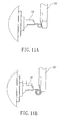
- the spring manufacturing machine changes the position of the metal wire led by the feeding chuck 18 of the wire feeder 10 through the axial driving devices 20, 30, 40. Further utilizing the special shapes and structures of the tool set 55, the spring manufacturing machine is able to manufacture various springs with different shapes and styles. As illustrated in figure 9A and figure 9B, by the displacement of the feeding chuck 18 the metal wire is able to change its position relative to the tool set 55. Further accordingly changing the rotational direction of the tool set 55, the spring manufacturing machine is able to perform an upward curving or a downward curving.
- a wire feeder driving mechanism for a spring manufacturing machine in accordance with the present invention has at least four merits.
- First, the installation of the axial driving devices enable the feeding chuck of the wire feeder to perform a two-dimensional or three-dimensional approach to the tool set. This unique design exempts a spring manufacturing machine from using a complicated tool seat driving mechanism of a conventional art. The labor hours for adjustment of the tool set is thereby greatly cut down.
- Second, the movement of the tool set of the present invention is linear. It is easy to quantify the position point of the tool set. The replacement or adjustment of the tool set can be performed by an ordinary operator.
- Third, the displacement data of the axial driving devices is forward to the computer controller to automatically and precisely control the feeding chuck to perform a desired motion.
- the feeding chuck of the present invention is able to perform a three-dimensional motion, the usage of a tool set is more efficient than that of the prior art.
- the present invention therefore remedies the tool seat deficiency problem of the prior art.
Landscapes
- Engineering & Computer Science (AREA)
- Mechanical Engineering (AREA)
- Wire Processing (AREA)
- Springs (AREA)
Abstract
Description
- The present invention relates in general to a spring manufacturing machine, and more particularly, to a wire feeder driving mechanism which enables a spring manufacturing machine to simplify the actuating mechanism of its tool seat and thereby significantly cuts down the labor hours consumed for adjustment of the tool set of the spring manufacturing machine. The present invention enhances the easiness and the convenience of the operation of the spring manufacturing machine. A spring manufacturing machine allowing a two-dimensional movement of the wire feeding church is known from
EP-0 804 978 . - Because springs are widely utilized in the shock absorbing or shock reducing, such as for automobiles, toys, electric appliances, switches, medical utilities, and so on, they have become an indispensable part of electric or mechanical equipments. The demand of spring shape becomes more and more versatile; it therefore cannot be satisfied by a conventional spring manufacturing machine. Accordingly, to develop a next generation product to satisfy the strong demand of the market is an important issue for persons skilled in the spring manufacturing machine.
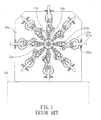
- Referring to figure 1, a conventional spring manufacturing machine includes a
machine base 10a and a work table 20a. Themachine base 10a is secured thereon a wire feeder 11a which has awire feeding chuck 12a at the front end thereof. Thefeeding chuck 12a is able to output the metal wire which will be formed into a spring. The work table 20a has afeeder hole 21a formed in the middle thereof which is able to receive thefeeding chuck 12a. A plurality of tool seats 22a are installed on the work table 20a. Each tool seat 22a includes a driving rod 221 a, arail cam 222a, and a tool set 223a. By utilizing the driving rod 221a and therail cam 222a, the tool set 223a is able to perform a linear or a curve motion for bending, winding, or cutting process of the metal wire. - However, the conventional spring manufacturing machine has several radical problems. First, to reduce the manufacturing cost a spring manufacturing machine is utilized to manufacture different kind of springs. To change the manufacturing process the tool seats 22a secured on the work table 20a need to be accordingly replaced and adjusted. The replacement and adjustment of the tool seats 22a are so time consuming that the production efficiency and economic benefit are very low. Second, a small deviation of the material quality, the heat treating process, or the wire diameter of the metal raw material will greatly influence the nature of the spring formed. Only a professional engineer is able to perform the adjustment and calibration of the conventional spring manufacturing machine. It is, therefore, hard to control the spring product's quality. Third, to perform a curve motion of the tool set 223a it is conventional to further install a complicated or adjustable driving member. This auxiliary driving member not only raises the material and manufacture cost but also increases the difficulty of assembling and maintenance. Fourth, when various manufacture industries' demand for spring configuration becomes more and more complicated, the tool seats 22a installed on the work table 20a for convention are not sufficient. It is unable to satisfy modem manufacture industries' demand.
- The present invention provides a wire feeder driving mechanism for a spring manufacturing machine, which enables a wire feeder to perform a two-dimensional or a three-dimensional motion through installation of a three-dimensional driving device. This invention successfully enables a spring manufacturing machine to simplify the actuating mechanism of its tool seat and thereby significantly cuts down the labor hours consumed for adjustment of the tool set of a spring manufacturing machine. The present invention enhances the easiness and the convenience of the operation and maintenance of a spring manufacturing machine.
- These and other objectives of the present invention will become obvious to those of ordinary skill in the art after reading the following detailed description of preferred embodiments.
- It is to be understood that both the foregoing general description and the following detailed description are exemplary, and are intended to provide further explanation of the invention as claimed.
- These as well as other features of the present invention will become more apparent upon reference to the drawings therein:
- Figure 1 is a front view of a conventional spring manufacturing machine.
- Figure 2 is an exploded view of a wire feeder driving mechanism not according to the present invention.
- Figure 3 is an exploded view of a first embodiment of the present invention.
- Figure 4 is a partial perspective view of the first embodiment of the present invention.
- Figure 5 is a perspective view of the first embodiment of the present invention.
- Figure 6 is a front view of the present invention.
- Figure 7 is a side view of the present invention.
- Figure 8 is partial front view of the spring manufacturing machine of the present invention illustrating the movement of the feeding chuck
- Figures 9A and 9B illustrate the curving process of the metal wire by utilizing the present invention.
- Figures 10A and 10B illustrate the bending process of the metal wire by utilizing the present invention.
- Figures 11A and 11B illustrate the winding process of the metal wire by utilizing the present invention.
- Reference will now be made in detail to the preferred embodiments of the present invention, examples of which are illustrated in the accompanying drawings. Wherever possible, the same reference numbers are used in the drawings and the description to refer to the same or like parts.
- Referring to figure 2, there is shown a wire feeder driving mechanism for a spring manufacturing machine. This wire feeder driving mechanism includes a
wire feeder 10, a firstaxial driving device 20, and a secondaxial driving device 30. To facilitate explanation, a three dimensional Cartesian coordinate system is further designated in some figures. - The
wire feeder 10 includes afeeding box 11, a reelingmotor 15, afeeding motor 16, afeeding chuck 18, and aspindle rotating motor 19. Thefeeding box 11 has afixing platform 12 installed at one side thereof. Ashaft mount 13 extends from thefixing platform 12. Ashaft hole 14 is formed at the center of theshaft mount 13. The reelingmotor 15 and thefeeding motor 16 are connected to the rear of thefeeding box 11. The reelingmotor 15 rotates a metal wire reel in order to supply thewire feeder 10 with a metal wire. Thefeeding motor 16 feeds forward the metal wire through the rotating of afeed roller set 17. Thefeeding chuck 18 has a central hole which is utilized to receive and forward the metal wire. Thespindle rotating motor 19 is able to drive and rotate thefeeding chuck 18, which facilitates processing the metal wire at different angles. - The first
axial driving device 20 can be disposed parallel with the X axis, the Y axis, or the Z axis of the spring manufacturing machine. Thefirst driving device 20 is in figure 2 parallel with the Y axis of the spring manufacturing machine. The firstaxial driving device 20 includes a Yaxis base body 21, aservo motor 22, a Yaxis lead screw 23, and aflange mount 24. The Yaxis base body 21 is constructed of ahorizontal board 211 and avertical frame 212, with a L-shaped configuration. Ashaft mount 213 is formed at and extends from the middle of one side of thehorizontal board 211. Ashaft hole 214 is bored from the center of theshaft mount 213. Thevertical frame 212 has parallel slide rails 215 installed at the both sides thereof. A plurality of slide blocks 216 are installed onto eachslide rail 215. Theslide block 216 is connected to the fixingplatform 12 of thewire feeder 10. Further, a fixedbrace 217 is formed at and extends from the top of thevertical frame 212. The fixedbrace 217 is utilized to install theservo motor 22. Theservo motor 22 has a motor shaft which is oriented toward and coupled to the Yaxis lead screw 23 through a shaft coupler or other mechanical elements. The Yaxis lead screw 23 is oriented parallel with the moving direction of theslide rail 215. Theflange mount 24 is screwed onto the Yaxis lead screw 23 with one end thereof received by theshaft hole 14 of thefeeding box 11 while the other end thereof secured on theshaft mount 13 of thefeeding box 11 through bolts and nuts or other means. - The second
axial driving device 30 can be disposed parallel with the X axis, the Y axis, or the Z axis of the spring manufacturing machine. In figure 2 thesecond driving device 30 is parallel with the X axis of the spring manufacturing machine. The moving direction of the secondaxial driving device 30 is thereby perpendicular to that of the firstaxial driving device 20. The secondaxial driving device 30 is secured on the spring manufacturing machine through bolts and nuts or other mechanical elements, and further assembled with the firstaxial driving device 20 to enable thewire feeder 10 to perform a two dimensional planar movement. The secondaxial driving device 30 includes a Xaxis base body 31, aservo motor 32, a Xaxis lead screw 33, and aflange mount 34. The Xaxis base body 31 is secured on the spring manufacturing machine through a plurality of bolts and nuts or other means. Ashaft mount 311 is formed at and extends from the middle of one side of Xaxis base body 31. Ashaft hole 312 is bored from the center of theshaft mount 311. The Xaxis base body 31 has parallel slide rails 313 installed thereon which are perpendicular with the direction of theshaft hole 312. A plurality of slide blocks 314 are installed onto eachslide rail 313. Thehorizontal board 211 of the Yaxis base body 21 is placed onto and connected with the slide blocks 314. Further, a fixedbrace 315 is formed at and extends from one side of the Xaxis base body 31. The fixedbrace 315 is utilized to install theservo motor 32. Theservo motor 32 has a motor shaft which is oriented toward and coupled to the Xaxis lead screw 33 through a shaft coupler and other mechanical elements. The Xaxis lead screw 33 is disposed parallel with the moving direction of theslide rail 313. Theflange mount 34 is screwed onto the Xaxis lead screw 33 with one end thereof received by theshaft hole 214 of the Yaxis base body 21 while the other end thereof secured on theshaft mount 213 of the Yaxis base body 21 through bolts or other means. - Referring to figure 3 through figure 5, an embodiment of the present invention further includes a third
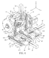
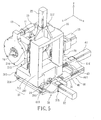
axial driving device 40 which is installed beneath the secondaxial driving device 30. The thirdaxial driving device 40 can be disposed parallel with the X axis, the Y axis, or the Z axis of the spring manufacturing machine. In the present embodiment the thirdaxial driving device 40 is parallel with the Z axis of the spring manufacturing machine. The moving direction of the thirdaxial driving device 40 is thereby perpendicular to those of the first and the secondaxial driving device axial driving device 40 is secured on the spring manufacturing machine through bolts and nuts or other means. The thirdaxial driving device 40 is further assembled with the first and the secondaxial driving device wire feeder 10 to perform a three-dimensional movement. The thirdaxial driving device 40 includes a Zaxis base body 41, aservo motor 42, a Zaxis lead screw 43, and aflange mount 44. The Zaxis base body 41 has a plurality of throughholes 411 formed thereon which are able to be inserted through by a plurality of bolts to secure the Zaxis base body 41 onto the spring manufacturing machine, respectively. The Zaxis base body 41 has parallel slide rails 412 installed on the top thereof. A plurality of slide blocks 413 are installed onto eachslide rail 412. The Xaxis base body 31 is placed onto and connected with the slide blocks 413. Further, a fixedbrace 414 is formed at and extends from one side of the Zaxis base body 41. The fixedbrace 414 is utilized to install theservo motor 42. Theservo motor 42 has a motor shaft which is oriented toward and coupled to the Zaxis lead screw 43 through a shaft coupler and other mechanical elements. The Zaxis lead screw 43 is oriented parallel with the moving direction of theslide rail 412. Theflange mount 44 is screwed onto the Zaxis lead screw 43 with one end thereof received by theshaft hole 312 of the Xaxis base body 31 while the other end thereof secured on theshaft mount 311 of the Xaxis base body 31 through bolts or other means. - Referring to figure 6 and figure 7, a
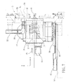
wire feeder 10 and a work table 52 are assembled onto themachine base 51 of thespring manufacturing machine 5. Thespring manufacturing machine 5 has themachine base 51 installed parallel with the Z axis thereof which is perpendicular to the X-Y plane. Themachine base 51 is a long rectangular prism in shape. The work table 52 is installed at the front end of themachine base 51, perpendicular to themachine base 51, and oriented parallel with the X-Y plane of thespring manufacturing machine 5. The work table 52 has acircular opening 53 formed in the middle thereof. Within thecircular opening 53, the feedingchuck 18 of thewire feeder 10 is able to move upward, downward, left, right, forth, or backward, or move toward a combined direction which combines with the mentioned directions. The work table 52 has a plurality oftool seats 54 mounted thereon. A variety of tool sets 55 with different functions are respectively secured to each front end of the tool seats 54. The tool set 55 is capable of moving linearly relative to thetool seat 54 or rotating through the driving of a servo motor. The linear motion of the tool set 55 enables the tool secured thereon to enter or leave the inner of thecircular opening 53. - Referring to figure 8, a partial front view of a spring manufacturing machine illustrates the operation of the present invention. By the actuation of a crank and linkage the tool set 55 is able to move linearly along the mounted direction of the
tool seat 54 into thecircular opening 53 of the work table 52. Further, theaxial driving devices wire feeder 10 to perform a desired displacement. The metal wire led by the feedingchuck 18 is thereby able to approach the tool set 55 through a two-dimensional or three-dimensional movement. Accordingly, the metal wire is capable of being manufactured into various spring final products with different complicated configurations. - Referring to figure 9 through figure 11, to process the metal wire into springs, the spring manufacturing machine changes the position of the metal wire led by the feeding
chuck 18 of thewire feeder 10 through theaxial driving devices chuck 18 the metal wire is able to change its position relative to the tool set 55. Further accordingly changing the rotational direction of the tool set 55, the spring manufacturing machine is able to perform an upward curving or a downward curving. As illustrated in figure 10A and figure 10B, by utilizing a concave curve tool of the tool set 55' an upward and a forward movement of the feedingchuck 18 are able to perform a preset angle bending process to the metal wire. As illustrated in figure 11A and figure 11B, by utilizing a slope tool of the tool set 55" varying the positions of the feedingchuck 18 changes the external diameter of the spiral spring. - A wire feeder driving mechanism for a spring manufacturing machine in accordance with the present invention has at least four merits. First, the installation of the axial driving devices enable the feeding chuck of the wire feeder to perform a two-dimensional or three-dimensional approach to the tool set. This unique design exempts a spring manufacturing machine from using a complicated tool seat driving mechanism of a conventional art. The labor hours for adjustment of the tool set is thereby greatly cut down. Second, the movement of the tool set of the present invention is linear. It is easy to quantify the position point of the tool set. The replacement or adjustment of the tool set can be performed by an ordinary operator. Third, the displacement data of the axial driving devices is forward to the computer controller to automatically and precisely control the feeding chuck to perform a desired motion. It is easy to adjust the position of the feeding chuck for a desired gap between the feeding chuck and the tool set. Fourth, because the feeding chuck of the present invention is able to perform a three-dimensional motion, the usage of a tool set is more efficient than that of the prior art. The present invention therefore remedies the tool seat deficiency problem of the prior art.
- While an illustrative and presently preferred embodiment of the invention has been described in detail herein, it is to be understood that the inventive concepts may be otherwise variously embodied and employed and that the appended claims are intended to be construed to include such variations.
Claims (7)
- A spring manufacturing machine used to process a wire, comprising:a machine base (51);a work table (52) fixed to one side of the machine base (51) and comprising a circular opening (53);- a wire feeder driving mechanism arranged on the machine base (51) and behind the work table (52), the wire feeder driving mechanism comprising:- a wire feeder (10) comprising a feeding box (11) and a feeding chuck (18) in front of the feeding box (11), the feeding box (11) being connected to a reeling motor (15) for rotating a wire reel in order to supply the wire feeder (10) with a metal wire, the feeding chuck (18) being connected to a spindle rotating motor (19) for driving and rotating the feeding chuck (18);- a first axial driving device (20) with one end connected to the wire feeder (10), having a first servo motor (22) for moving the wire feeder (10) in a first direction; and- a second axial driving device (30) with one end connected to the first axial driving device (20), and having a second servo motor (32) for moving the first axial driving device (20) in a second direction perpendicular to the first direction; and- a third axial driving device (40) with one end connected to the second axial driving device (30) and the other end connected to the machine base (51), for moving the second axial driving device (30) in a third direction perpendicular to both the first direction and the second direction so that the feeding chuck (18) of the wire feeder (10) is able to perform a three-dimensional movement in the circular opening (53) of the work table.
- The spring manufacturing machine of Claim 1, wherein the first axial driving device (20) further comprises:- a first axis base body (21) having at least one slide rail (215) and at least one slide block (216) installed thereon;- a fixed brace (217) secured to one end of the first axis base body (21);- the first servo motor (22) installed inside the fixed brace;- a first axis lead screw (23) with one end inserted into the fixed brace (217) and coupled to a shaft of the first servo motor (22), which is oriented parallel with a moving direction of the slide block (216); and- a flange mount (24) screwed onto the first axis lead screw (23) and securely connected to the wire feeder (10).
- The spring manufacturing machine of Claim 1, wherein the second axial driving device (30) comprises:- a second axis base body (31), having at least one slide rail (313) and at least one slide block (314) installed thereon;- a fixed brace (315) secured to one end of the second axis base body (31);- the second servo motor (32) installed inside the fixed brace (315);- a second axis lead screw (33) with one end inserted into the fixed brace (315) and coupled to a shaft of the second servo motor (32), which is oriented parallel with a moving direction of the slide block (314); and- a flange mount (34) screwed onto the second axis lead screw (33), and securely connected to the first axial driving device (20).
- The spring manufacturing machine of Claim 1, wherein the third axial driving device (40) comprises:- a third axis base body (41) secured on the machine base (51), having at least one slide rail (412) and at least one slide block (413) installed thereon;- a fixed brace (414) secured to one end of the third axis base body (40);- the third servo motor (42) installed inside the fixed brace (414);- a third axis lead screw (43) with one end inserted into the fixed brace (414) and coupled to a shaft of the third servo motor (42), which is oriented parallel with a moving direction of the slide block (413); and- a flange mount (44) screwed onto the third axis lead screw (43), and securely connected to the second axial driving device (30).
- The spring manufacturing machine of Claim 1, wherein the first axial driving device (20) is adapted to move along a vertical direction of the spring manufacturing machine, the second axial driving device (30) is adapted to move along a first horizontal direction of the spring manufacturing machine and the third axial driving device (40) is adapted to move along a second horizontal direction of the spring manufacturing machine.
- The spring manufacturing machine of Claim 1, wherein the second axial driving device (30) is adapted to move along a vertical direction of the spring manufacturing machine, the first axial driving device (20) is adapted to move along a first horizontal direction of the spring manufacturing machine and the third axial driving device (40) is adapted to move along a second horizontal direction of the spring manufacturing machine.
- The spring manufacturing machine of Claim 1, wherein the third axial driving device (40) is adapted to move along a vertical direction of the spring manufacturing machine, the first axial driving device (20) is adapted to move along a first horizontal direction of the spring manufacturing machine and the second axial driving device (30) is adapted to move along a second horizontal direction of the spring manufacturing machine.
Priority Applications (4)
| Application Number | Priority Date | Filing Date | Title |
|---|---|---|---|
| PL04022427T PL1637251T3 (en) | 2004-09-21 | 2004-09-21 | Spring manufacturing machine comprising a wire feeder driving mechanism |
| AT04022427T ATE377466T1 (en) | 2004-09-21 | 2004-09-21 | SPRING FORMING MACHINE WITH A WIRE FEED UNIT |
| EP04022427A EP1637251B1 (en) | 2004-09-21 | 2004-09-21 | Spring manufacturing machine comprising a wire feeder driving mechanism |
| DE602004009928T DE602004009928T2 (en) | 2004-09-21 | 2004-09-21 | Spring forming machine with a wire feed unit |
Applications Claiming Priority (1)
| Application Number | Priority Date | Filing Date | Title |
|---|---|---|---|
| EP04022427A EP1637251B1 (en) | 2004-09-21 | 2004-09-21 | Spring manufacturing machine comprising a wire feeder driving mechanism |
Publications (2)
| Publication Number | Publication Date |
|---|---|
| EP1637251A1 EP1637251A1 (en) | 2006-03-22 |
| EP1637251B1 true EP1637251B1 (en) | 2007-11-07 |
Family
ID=34926645
Family Applications (1)
| Application Number | Title | Priority Date | Filing Date |
|---|---|---|---|
| EP04022427A Not-in-force EP1637251B1 (en) | 2004-09-21 | 2004-09-21 | Spring manufacturing machine comprising a wire feeder driving mechanism |
Country Status (4)
| Country | Link |
|---|---|
| EP (1) | EP1637251B1 (en) |
| AT (1) | ATE377466T1 (en) |
| DE (1) | DE602004009928T2 (en) |
| PL (1) | PL1637251T3 (en) |
Families Citing this family (4)
| Publication number | Priority date | Publication date | Assignee | Title |
|---|---|---|---|---|
| DE102007031514A1 (en) | 2007-07-06 | 2009-01-08 | Wafios Ag | Wire forming machine |
| DE102011007183A1 (en) * | 2011-04-12 | 2012-10-18 | Wafios Ag | Method and system for programming the control of a multi-axis forming machine and forming machine |
| CN106455332B (en) * | 2016-11-15 | 2018-12-04 | 东莞东聚电子电讯制品有限公司 | The automatic bending positioning mechanism of vision |
| CN110227772B (en) * | 2019-07-11 | 2024-01-30 | 陶永亮 | Manufacturing machine for long tail clamp handle |
Family Cites Families (4)
| Publication number | Priority date | Publication date | Assignee | Title |
|---|---|---|---|---|
| IT1282393B1 (en) * | 1996-05-02 | 1998-03-20 | Omd Spa | TWISTING OR BENDING MACHINE PARTICULARLY DESIGNED FOR THE MANUFACTURE OF SIMPLE AND DOUBLE TORSION SPRINGS |
| JP2939472B1 (en) * | 1998-08-21 | 1999-08-25 | 株式会社板屋製作所 | Spring manufacturing equipment |
| DE10100387C2 (en) * | 2001-01-05 | 2003-05-22 | Tang Well Tech Co | Power transmission control system for a wire forming machine |
| JP4125152B2 (en) * | 2003-02-10 | 2008-07-30 | 新興機械工業株式会社 | Spring making machine |
-
2004
- 2004-09-21 AT AT04022427T patent/ATE377466T1/en not_active IP Right Cessation
- 2004-09-21 EP EP04022427A patent/EP1637251B1/en not_active Not-in-force
- 2004-09-21 PL PL04022427T patent/PL1637251T3/en unknown
- 2004-09-21 DE DE602004009928T patent/DE602004009928T2/en active Active
Also Published As
| Publication number | Publication date |
|---|---|
| ATE377466T1 (en) | 2007-11-15 |
| PL1637251T3 (en) | 2008-03-31 |
| EP1637251A1 (en) | 2006-03-22 |
| DE602004009928T2 (en) | 2008-08-21 |
| DE602004009928D1 (en) | 2007-12-20 |
Similar Documents
| Publication | Publication Date | Title |
|---|---|---|
| US7134305B2 (en) | Wire feeder driving mechanism for spring manufacturing machine | |
| TWI337903B (en) | Wire-forming machine | |
| JP5325369B2 (en) | Spring making machine | |
| US20140165348A1 (en) | Machine tool with lathe tool and milling cutter | |
| EP3195952B1 (en) | Omnidirectional manipulator for use with spring forming machine | |
| CN103567799B (en) | Feed arrangement and apply the lathe of this feed arrangement | |
| US20120107064A1 (en) | CNC Machine Tool Having Two Spindles | |
| KR200486232Y1 (en) | Servo-Rotating All-Function Tool Module for Use With Spring Forming Machine | |
| JP5798162B2 (en) | Wire forming equipment | |
| JPH08174120A (en) | Wire forming device | |
| EP1637251B1 (en) | Spring manufacturing machine comprising a wire feeder driving mechanism | |
| US8336353B2 (en) | Coil spring manufacturing machine | |
| US20140020527A1 (en) | Machine tool with uninterrupted cutting | |
| KR101770569B1 (en) | Automatic transferring device for moter shaft | |
| US6571591B2 (en) | Spring manufacturing apparatus and wire guide used for the same | |
| JP4336637B2 (en) | Wire feeder drive mechanism in spring manufacturing equipment | |
| KR20200142755A (en) | Wood forming apparatus easy to make curved shape | |
| JP5371212B2 (en) | Spring making machine | |
| CN201596805U (en) | Curved-surface cutting device | |
| KR20090041233A (en) | Structure head for steel wire bending machine | |
| JP5366143B2 (en) | Coil spring manufacturing apparatus and coil spring manufacturing method | |
| KR200370821Y1 (en) | Wire feeder driving mechanism for spring manufacturing machine | |
| CN203956649U (en) | Digital cuttings equipment for grinding | |
| US9238306B2 (en) | Feeding device and machine tool using the same | |
| US6185981B1 (en) | Transmission control system for a wire forming machine |
Legal Events
| Date | Code | Title | Description |
|---|---|---|---|
| PUAI | Public reference made under article 153(3) epc to a published international application that has entered the european phase |
Free format text: ORIGINAL CODE: 0009012 |
|
| 17P | Request for examination filed |
Effective date: 20050707 |
|
| AK | Designated contracting states |
Kind code of ref document: A1 Designated state(s): AT BE BG CH CY CZ DE DK EE ES FI FR GB GR HU IE IT LI LU MC NL PL PT RO SE SI SK TR |
|
| AX | Request for extension of the european patent |
Extension state: AL HR LT LV MK |
|
| 17Q | First examination report despatched |
Effective date: 20060201 |
|
| AKX | Designation fees paid |
Designated state(s): AT BE BG CH CY CZ DE DK EE ES FI FR GB GR HU IE IT LI LU MC NL PL PT RO SE SI SK TR |
|
| GRAP | Despatch of communication of intention to grant a patent |
Free format text: ORIGINAL CODE: EPIDOSNIGR1 |
|
| RTI1 | Title (correction) |
Free format text: SPRING MANUFACTURING MACHINE COMPRISING A WIRE FEEDER DRIVING MECHANISM |
|
| GRAS | Grant fee paid |
Free format text: ORIGINAL CODE: EPIDOSNIGR3 |
|
| GRAA | (expected) grant |
Free format text: ORIGINAL CODE: 0009210 |
|
| AK | Designated contracting states |
Kind code of ref document: B1 Designated state(s): AT BE BG CH CY CZ DE DK EE ES FI FR GB GR HU IE IT LI LU MC NL PL PT RO SE SI SK TR |
|
| REG | Reference to a national code |
Ref country code: GB Ref legal event code: FG4D |
|
| REG | Reference to a national code |
Ref country code: IE Ref legal event code: FG4D |
|
| REG | Reference to a national code |
Ref country code: CH Ref legal event code: EP |
|
| REF | Corresponds to: |
Ref document number: 602004009928 Country of ref document: DE Date of ref document: 20071220 Kind code of ref document: P |
|
| REG | Reference to a national code |
Ref country code: PL Ref legal event code: T3 |
|
| PG25 | Lapsed in a contracting state [announced via postgrant information from national office to epo] |
Ref country code: LI Free format text: LAPSE BECAUSE OF FAILURE TO SUBMIT A TRANSLATION OF THE DESCRIPTION OR TO PAY THE FEE WITHIN THE PRESCRIBED TIME-LIMIT Effective date: 20071107 Ref country code: SE Free format text: LAPSE BECAUSE OF FAILURE TO SUBMIT A TRANSLATION OF THE DESCRIPTION OR TO PAY THE FEE WITHIN THE PRESCRIBED TIME-LIMIT Effective date: 20080207 Ref country code: NL Free format text: LAPSE BECAUSE OF FAILURE TO SUBMIT A TRANSLATION OF THE DESCRIPTION OR TO PAY THE FEE WITHIN THE PRESCRIBED TIME-LIMIT Effective date: 20071107 Ref country code: ES Free format text: LAPSE BECAUSE OF FAILURE TO SUBMIT A TRANSLATION OF THE DESCRIPTION OR TO PAY THE FEE WITHIN THE PRESCRIBED TIME-LIMIT Effective date: 20080218 Ref country code: CH Free format text: LAPSE BECAUSE OF FAILURE TO SUBMIT A TRANSLATION OF THE DESCRIPTION OR TO PAY THE FEE WITHIN THE PRESCRIBED TIME-LIMIT Effective date: 20071107 |
|
| NLV1 | Nl: lapsed or annulled due to failure to fulfill the requirements of art. 29p and 29m of the patents act | ||
| PG25 | Lapsed in a contracting state [announced via postgrant information from national office to epo] |
Ref country code: SI Free format text: LAPSE BECAUSE OF FAILURE TO SUBMIT A TRANSLATION OF THE DESCRIPTION OR TO PAY THE FEE WITHIN THE PRESCRIBED TIME-LIMIT Effective date: 20071107 Ref country code: BG Free format text: LAPSE BECAUSE OF FAILURE TO SUBMIT A TRANSLATION OF THE DESCRIPTION OR TO PAY THE FEE WITHIN THE PRESCRIBED TIME-LIMIT Effective date: 20080207 |
|
| REG | Reference to a national code |
Ref country code: CH Ref legal event code: PL |
|
| ET | Fr: translation filed | ||
| PG25 | Lapsed in a contracting state [announced via postgrant information from national office to epo] |
Ref country code: AT Free format text: LAPSE BECAUSE OF FAILURE TO SUBMIT A TRANSLATION OF THE DESCRIPTION OR TO PAY THE FEE WITHIN THE PRESCRIBED TIME-LIMIT Effective date: 20071107 |
|
| PG25 | Lapsed in a contracting state [announced via postgrant information from national office to epo] |
Ref country code: DK Free format text: LAPSE BECAUSE OF FAILURE TO SUBMIT A TRANSLATION OF THE DESCRIPTION OR TO PAY THE FEE WITHIN THE PRESCRIBED TIME-LIMIT Effective date: 20071107 |
|
| PG25 | Lapsed in a contracting state [announced via postgrant information from national office to epo] |
Ref country code: RO Free format text: LAPSE BECAUSE OF FAILURE TO SUBMIT A TRANSLATION OF THE DESCRIPTION OR TO PAY THE FEE WITHIN THE PRESCRIBED TIME-LIMIT Effective date: 20071107 Ref country code: SK Free format text: LAPSE BECAUSE OF FAILURE TO SUBMIT A TRANSLATION OF THE DESCRIPTION OR TO PAY THE FEE WITHIN THE PRESCRIBED TIME-LIMIT Effective date: 20071107 |
|
| PLBE | No opposition filed within time limit |
Free format text: ORIGINAL CODE: 0009261 |
|
| STAA | Information on the status of an ep patent application or granted ep patent |
Free format text: STATUS: NO OPPOSITION FILED WITHIN TIME LIMIT |
|
| PG25 | Lapsed in a contracting state [announced via postgrant information from national office to epo] |
Ref country code: PT Free format text: LAPSE BECAUSE OF FAILURE TO SUBMIT A TRANSLATION OF THE DESCRIPTION OR TO PAY THE FEE WITHIN THE PRESCRIBED TIME-LIMIT Effective date: 20080407 |
|
| 26N | No opposition filed |
Effective date: 20080808 |
|
| PG25 | Lapsed in a contracting state [announced via postgrant information from national office to epo] |
Ref country code: GR Free format text: LAPSE BECAUSE OF FAILURE TO SUBMIT A TRANSLATION OF THE DESCRIPTION OR TO PAY THE FEE WITHIN THE PRESCRIBED TIME-LIMIT Effective date: 20080208 |
|
| PG25 | Lapsed in a contracting state [announced via postgrant information from national office to epo] |
Ref country code: FI Free format text: LAPSE BECAUSE OF FAILURE TO SUBMIT A TRANSLATION OF THE DESCRIPTION OR TO PAY THE FEE WITHIN THE PRESCRIBED TIME-LIMIT Effective date: 20071107 |
|
| PG25 | Lapsed in a contracting state [announced via postgrant information from national office to epo] |
Ref country code: EE Free format text: LAPSE BECAUSE OF FAILURE TO SUBMIT A TRANSLATION OF THE DESCRIPTION OR TO PAY THE FEE WITHIN THE PRESCRIBED TIME-LIMIT Effective date: 20071107 Ref country code: MC Free format text: LAPSE BECAUSE OF NON-PAYMENT OF DUE FEES Effective date: 20080930 |
|
| PG25 | Lapsed in a contracting state [announced via postgrant information from national office to epo] |
Ref country code: IE Free format text: LAPSE BECAUSE OF NON-PAYMENT OF DUE FEES Effective date: 20080922 Ref country code: CY Free format text: LAPSE BECAUSE OF FAILURE TO SUBMIT A TRANSLATION OF THE DESCRIPTION OR TO PAY THE FEE WITHIN THE PRESCRIBED TIME-LIMIT Effective date: 20071107 |
|
| PG25 | Lapsed in a contracting state [announced via postgrant information from national office to epo] |
Ref country code: LU Free format text: LAPSE BECAUSE OF NON-PAYMENT OF DUE FEES Effective date: 20080921 Ref country code: HU Free format text: LAPSE BECAUSE OF FAILURE TO SUBMIT A TRANSLATION OF THE DESCRIPTION OR TO PAY THE FEE WITHIN THE PRESCRIBED TIME-LIMIT Effective date: 20080508 |
|
| PGFP | Annual fee paid to national office [announced via postgrant information from national office to epo] |
Ref country code: TR Payment date: 20140912 Year of fee payment: 11 |
|
| REG | Reference to a national code |
Ref country code: FR Ref legal event code: PLFP Year of fee payment: 12 |
|
| PGFP | Annual fee paid to national office [announced via postgrant information from national office to epo] |
Ref country code: CZ Payment date: 20150917 Year of fee payment: 12 |
|
| PGFP | Annual fee paid to national office [announced via postgrant information from national office to epo] |
Ref country code: BE Payment date: 20150921 Year of fee payment: 12 Ref country code: FR Payment date: 20150916 Year of fee payment: 12 Ref country code: PL Payment date: 20150910 Year of fee payment: 12 |
|
| PGFP | Annual fee paid to national office [announced via postgrant information from national office to epo] |
Ref country code: GB Payment date: 20160914 Year of fee payment: 13 Ref country code: DE Payment date: 20160926 Year of fee payment: 13 |
|
| PG25 | Lapsed in a contracting state [announced via postgrant information from national office to epo] |
Ref country code: BE Free format text: LAPSE BECAUSE OF NON-PAYMENT OF DUE FEES Effective date: 20160930 |
|
| PGFP | Annual fee paid to national office [announced via postgrant information from national office to epo] |
Ref country code: IT Payment date: 20160927 Year of fee payment: 13 |
|
| PG25 | Lapsed in a contracting state [announced via postgrant information from national office to epo] |
Ref country code: CZ Free format text: LAPSE BECAUSE OF NON-PAYMENT OF DUE FEES Effective date: 20160921 |
|
| REG | Reference to a national code |
Ref country code: FR Ref legal event code: ST Effective date: 20170531 |
|
| PG25 | Lapsed in a contracting state [announced via postgrant information from national office to epo] |
Ref country code: FR Free format text: LAPSE BECAUSE OF NON-PAYMENT OF DUE FEES Effective date: 20160930 |
|
| REG | Reference to a national code |
Ref country code: BE Ref legal event code: MM Effective date: 20160930 |
|
| PG25 | Lapsed in a contracting state [announced via postgrant information from national office to epo] |
Ref country code: PL Free format text: LAPSE BECAUSE OF NON-PAYMENT OF DUE FEES Effective date: 20160921 |
|
| REG | Reference to a national code |
Ref country code: DE Ref legal event code: R119 Ref document number: 602004009928 Country of ref document: DE |
|
| GBPC | Gb: european patent ceased through non-payment of renewal fee |
Effective date: 20170921 |
|
| PG25 | Lapsed in a contracting state [announced via postgrant information from national office to epo] |
Ref country code: DE Free format text: LAPSE BECAUSE OF NON-PAYMENT OF DUE FEES Effective date: 20180404 Ref country code: GB Free format text: LAPSE BECAUSE OF NON-PAYMENT OF DUE FEES Effective date: 20170921 |
|
| PG25 | Lapsed in a contracting state [announced via postgrant information from national office to epo] |
Ref country code: IT Free format text: LAPSE BECAUSE OF NON-PAYMENT OF DUE FEES Effective date: 20170921 |
|
| PG25 | Lapsed in a contracting state [announced via postgrant information from national office to epo] |
Ref country code: TR Free format text: LAPSE BECAUSE OF NON-PAYMENT OF DUE FEES Effective date: 20160921 |