EP2431122A1 - Apparatus for control of electromagnetic chuck of multi channel type - Google Patents
Apparatus for control of electromagnetic chuck of multi channel type Download PDFInfo
- Publication number
- EP2431122A1 EP2431122A1 EP11168618A EP11168618A EP2431122A1 EP 2431122 A1 EP2431122 A1 EP 2431122A1 EP 11168618 A EP11168618 A EP 11168618A EP 11168618 A EP11168618 A EP 11168618A EP 2431122 A1 EP2431122 A1 EP 2431122A1
- Authority
- EP
- European Patent Office
- Prior art keywords
- magnetic chuck
- unit
- channel
- control
- main control
- Prior art date
- Legal status (The legal status is an assumption and is not a legal conclusion. Google has not performed a legal analysis and makes no representation as to the accuracy of the status listed.)
- Granted
Links
- 230000005415 magnetization Effects 0.000 claims abstract description 20
- 238000000926 separation method Methods 0.000 claims abstract description 13
- 230000005347 demagnetization Effects 0.000 claims description 16
- 230000005389 magnetism Effects 0.000 claims description 4
- 238000000034 method Methods 0.000 abstract description 4
- 238000010586 diagram Methods 0.000 description 3
- 238000007796 conventional method Methods 0.000 description 2
- 230000000903 blocking effect Effects 0.000 description 1
Images
Classifications
-
- B—PERFORMING OPERATIONS; TRANSPORTING
- B23—MACHINE TOOLS; METAL-WORKING NOT OTHERWISE PROVIDED FOR
- B23Q—DETAILS, COMPONENTS, OR ACCESSORIES FOR MACHINE TOOLS, e.g. ARRANGEMENTS FOR COPYING OR CONTROLLING; MACHINE TOOLS IN GENERAL CHARACTERISED BY THE CONSTRUCTION OF PARTICULAR DETAILS OR COMPONENTS; COMBINATIONS OR ASSOCIATIONS OF METAL-WORKING MACHINES, NOT DIRECTED TO A PARTICULAR RESULT
- B23Q3/00—Devices holding, supporting, or positioning work or tools, of a kind normally removable from the machine
- B23Q3/15—Devices for holding work using magnetic or electric force acting directly on the work
- B23Q3/154—Stationary devices
- B23Q3/1546—Stationary devices using permanent magnets
-
- H—ELECTRICITY
- H01—ELECTRIC ELEMENTS
- H01F—MAGNETS; INDUCTANCES; TRANSFORMERS; SELECTION OF MATERIALS FOR THEIR MAGNETIC PROPERTIES
- H01F13/00—Apparatus or processes for magnetising or demagnetising
Definitions
- the present invention relates to a permanent electromagnetic chuck, and more specifically, to a channel separation type magnetic chuck control device, in which the entire or only a part of the magnetic chuck is magnetized in order to efficiently process the work piece when clamping a work piece at a machine tool, and thus the work piece can be independently clamped for each channel to be suitable for the characteristics of the work piece such as the size and the like.
- a conventional permanent electromagnetic chuck is a device for clamping a work piece to prevent movement of the work piece when processing the work piece using a machine tool.
- the magnetic chuck is magnetized by repeatedly supplying or blocking power of the magnetic chuck, and thus magnetization or demagnetization is performed on the work piece.
- the conventional permanent electromagnetic chuck is fixed to the table of a machine tool, and the entire magnetic chuck is magnetized by supplying power only once regardless of the size of the permanent electromagnetic chuck in order to clamp the work piece.
- the work piece is in the form of a small chip, adjacent work pieces, as well as the work piece to be processed, are simultaneously magnetized at the magnetic chuck, and thus if the work piece is demagnetized in order to adjust the magnetization, all of the work pieces are demagnetized. Therefore, the position of the work piece should be re-set in order to prevent this phenomenon.
- the permanent electromagnetic chuck according to the conventional technique cannot adjust strength of magnetic power. Although it is possible to adjust the strength of magnetic power, since the entire area of the magnetic chuck is magnetized with the same strength, it is difficult to process a variety of materials that should be clamped with different magnetic forces by clamping the materials only once.
- the present invention has been made in view of the above-mentioned problems occurring in the prior art, and it is an object of the present invention to provide a channel separation type magnetic chuck control device, in which the entire or only a part of the magnetic chuck that clamps a work piece at a machine tool is selectively magnetized, and thus the work piece can be independently clamped for each channel to be suitable for the characteristics of the work piece such as the size and the like, thereby efficiently processing the work piece.
- a channel separation type magnetic chuck control device comprising a main control device for receiving AC power through a main power input unit and controlling drive of a magnetic chuck and a magnetic chuck driving unit for driving magnetization of the magnetic chuck that is separated and independently driven as a plurality of channels under a control of the main control device, wherein the main control device includes: a current sensing unit for sensing input of main power from the main power input unit and input of driving power for the magnetic chuck driving unit of each separated channel, a control input unit for controlling selective magnetism and magnetizing strength of the magnetic chuck for each channel, a main control unit for outputting a driving signal for demagnetization, magnetization, and magnetizing strength of a magnetic chuck selected by a control signal inputted from the control input unit and sensing whether or not the magnetic chuck is driven by a current value inputted through the current sensing unit, a pulse output unit for outputting a driving pulse for adjusting magnetizing strength of the magnetic
- the control input unit includes: a channel selection unit for sensing a channel selected by a user and an on/off state of the corresponding channel and inputting the on/off state into the main control unit; an external PLC control unit for transferring a magnetic chuck control signal inputted from an external PLC control device to the main control unit; and a remote control unit for receiving a remote signal for controlling magnetization, demagnetization, and magnetizing strength of the magnetic chuck for each channel in a wired or wireless manner and outputting the remote control signal to the main control unit.
- the channel separation type magnetic chuck control device is effective in that since the entire or a part of a magnetic chuck that clamps a work piece at a machine tool is selectively magnetized, and thus the work piece can be independently driven for each channel to be suitable for the characteristics of the work piece such as the size and the like, only the work piece desired to be processed can be clamped without giving affects to the other adjacent work pieces.
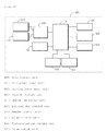
- FIG. 1 is a block diagram showing the configuration of a main control unit of a two-channel separation type magnetic chuck control device according to an embodiment of the present invention.
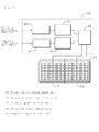
- FIG. 2 is a block diagram showing the configuration of a magnetic chuck driving unit of a two-channel separation type magnetic chuck control device according to an embodiment of the present invention.
- FIGs. 1 and 2 are block diagrams showing the entire configuration of a two-channel separation type magnetic chuck control device according to an embodiment of the present invention.
- the two-channel separation type magnetic chuck control device comprises a magnetic chuck 170 including two channels 171 and 172 for clamping a work piece by magnetizing or demagnetizing the work piece in order to process the work piece, a magnetic chuck driving unit 102 for controlling supply of current in order to magnetize and demagnetize the work piece with selected magnetizing strength of the magnetic chuck 170, and a main control device 101 for outputting an on/off and magnetizing strength control signal for driving a magnetic chuck of a channel selected by a user to the magnetic chuck driving unit 102.
- the main control device 101 includes a main power input unit and a driving power input unit 111 and 112 for receiving AC power, a current sensing unit 113 for sensing input of main power and input of driving power for the magnetic chuck driving unit 102 of each channel from the main power input unit and the driving power input unit 111 and 112, a control input unit 121 to 123 for controlling selective magnetism and magnetizing strength of the magnetic chucks 171 and 172 for each channel, a main control unit 110 for outputting a driving signal for demagnetization, magnetization, and magnetizing strength of a magnetic chuck selected by a control signal inputted from the control input unit 121 to 123 and sensing whether or not the magnetic chuck is driven by a current value inputted through the current sensing unit 113, a pulse output unit 114 for outputting a driving pulse for adjusting magnetizing strength of the magnetic chuck selected by the magnetic chuck driving unit 102 under the control of the main control unit 110, a relay driving unit 131 for selectively driving magnetization or demagnet
- the magnetic chuck driving unit 102 includes first and second control signal input units 141 and 142 for inputting a magnetic chuck control signal into each channel from the main control device 101, first and second AC power control units 151 and 152 for controlling AC powers respectively inputted by the magnetic chuck control signals inputted through the first and second control signal input units 141 and 142, and a magnetic chuck control unit 161 for controlling magnetization, demagnetization, and magnetizing strength by supplying current signals outputted through the first and second AC power control units 151 and 152 to the magnetic chuck 170 of a corresponding channel.
- control input unit 121 to 123 includes a channel selection unit 121 for sensing a channel selected by a user and an on/off state of the corresponding channel and inputting the on/off state into the main control unit 110, an external PLC control unit 122 for transferring a magnetic chuck control signal inputted from an external PLC control device to the main control unit 110, and a remote control unit 123 for receiving a remote signal for controlling magnetization, demagnetization, and magnetizing strength of the magnetic chucks 171 and 172 for each channel in a wired or wireless manner and outputting the remote control signal to the main control unit 110.
- the magnetic chucks 171 and 172 separated for each channel are driven for a corresponding channel at a selected magnetizing strength depending on the selection of the user.
- the main control unit 110 senses a signal inputted through the channel selection unit 121, the external PLC control unit 122, or the remote control unit 123 and generates a signal for driving the magnetic chuck 171 and 172 of a corresponding channel.
- the magnetic strength at the time of the magnetization inputted through the remote control unit 123 is divided into 5 levels as shown in Table 1 and set to drive the magnetic chuck at 50 to 100% of the magnetizing strength in each level.
- the magnetizing strength cannot be adjusted if the magnetization state and the magnetic chuck 171 and 172 of each channel are simultaneously turned off, and the magnetizing strength can be adjusted only when the magnetic chuck is in a demagnetization state.
- the magnetizing strength is set not to be adjusted so that the clamped work piece cannot get out of its position by the change of the magnetic strength.
- the main control unit 110 senses the control signal for controlling the magnetic chuck 171 and 172 of a corresponding channel selected through the control input unit 121 to 123 and drives the magnetic chuck 171 and 172 of a corresponding channel by driving the relay driving unit 131.
- the main control unit 110 outputs the magnetizing strength of the magnetic chuck 171 and 172 of each channel through the pulse output unit 141 as shown in Table 1.
- the pulse output unit 141 supplies a pulse for driving a triac for controlling current at the AC power control units 151 and 152 of the magnetic chuck driving unit 102.
- the magnetic chuck driving unit 102 receives the magnetic chuck control signal of a corresponding channel inputted through the first and second control signal input units 141 and 142 and drives a corresponding triac of respective AC power control units 151 and 152 using current corresponding to the set magnetizing strength. Based on the current value controlled and outputted from the AC power control units 151 and 152, the magnetic chuck control unit 161 controls the inputted power to drive the magnetic chuck 171 and 172 of a corresponding channel with the set magnetizing strength.
- each work piece set to a corresponding position is clamped and processed.
- the work piece magnetized at the magnetic chuck 171 and 172 of a corresponding channel is demagnetized.
- the demagnetization is accomplished regardless of the magnetized level.
- the channel separation type magnetic chuck control device described above is not limited to the embodiments, but can be modified in a variety of ways depending on the number of channels and magnetizing strength of the magnetic chuck, and magnetic chuck control means of the control input unit can be diversely modified. It is to be appreciated that those skilled in the art can change or modify the embodiments without departing from the scope and spirit of the present invention.
Landscapes
- Engineering & Computer Science (AREA)
- Power Engineering (AREA)
- Mechanical Engineering (AREA)
- Jigs For Machine Tools (AREA)
Abstract
Description
- The present invention relates to a permanent electromagnetic chuck, and more specifically, to a channel separation type magnetic chuck control device, in which the entire or only a part of the magnetic chuck is magnetized in order to efficiently process the work piece when clamping a work piece at a machine tool, and thus the work piece can be independently clamped for each channel to be suitable for the characteristics of the work piece such as the size and the like.
- A conventional permanent electromagnetic chuck is a device for clamping a work piece to prevent movement of the work piece when processing the work piece using a machine tool. The magnetic chuck is magnetized by repeatedly supplying or blocking power of the magnetic chuck, and thus magnetization or demagnetization is performed on the work piece.
- The conventional permanent electromagnetic chuck is fixed to the table of a machine tool, and the entire magnetic chuck is magnetized by supplying power only once regardless of the size of the permanent electromagnetic chuck in order to clamp the work piece.
- However, in the permanent electromagnetic chuck according to a conventional technique, since magnetism is generated at the entire permanent electromagnetic chuck even when a work piece that is small compared to the size of the magnetic chuck is clamped, a lot of work pieces are magnetized at the empty permanent electromagnetic chuck when the small work piece is processed.
- That is, if the work piece is in the form of a small chip, adjacent work pieces, as well as the work piece to be processed, are simultaneously magnetized at the magnetic chuck, and thus if the work piece is demagnetized in order to adjust the magnetization, all of the work pieces are demagnetized. Therefore, the position of the work piece should be re-set in order to prevent this phenomenon.
- If the adjacent work pieces are simultaneously magnetized by the magnetic chuck when work pieces previously processed by a prior work exist together with a work piece waiting for being processed, it takes time to separate the work piece from the previously processed work pieces, and the previously processed work pieces should be moved to another positions. Therefore, there is a problem in that it is inconvenient and requires a large work space.
- In addition, the permanent electromagnetic chuck according to the conventional technique cannot adjust strength of magnetic power. Although it is possible to adjust the strength of magnetic power, since the entire area of the magnetic chuck is magnetized with the same strength, it is difficult to process a variety of materials that should be clamped with different magnetic forces by clamping the materials only once.
- Accordingly, the present invention has been made in view of the above-mentioned problems occurring in the prior art, and it is an object of the present invention to provide a channel separation type magnetic chuck control device, in which the entire or only a part of the magnetic chuck that clamps a work piece at a machine tool is selectively magnetized, and thus the work piece can be independently clamped for each channel to be suitable for the characteristics of the work piece such as the size and the like, thereby efficiently processing the work piece.
- To accomplish the above objects, according to an aspect of the present invention, there is provided a channel separation type magnetic chuck control device comprising a main control device for receiving AC power through a main power input unit and controlling drive of a magnetic chuck and a magnetic chuck driving unit for driving magnetization of the magnetic chuck that is separated and independently driven as a plurality of channels under a control of the main control device, wherein the main control device includes: a current sensing unit for sensing input of main power from the main power input unit and input of driving power for the magnetic chuck driving unit of each separated channel, a control input unit for controlling selective magnetism and magnetizing strength of the magnetic chuck for each channel, a main control unit for outputting a driving signal for demagnetization, magnetization, and magnetizing strength of a magnetic chuck selected by a control signal inputted from the control input unit and sensing whether or not the magnetic chuck is driven by a current value inputted through the current sensing unit, a pulse output unit for outputting a driving pulse for adjusting magnetizing strength of the magnetic chuck selected by the magnetic chuck driving unit under the control of the main control unit, a relay driving unit for selectively driving magnetization or demagnetization of the magnetic chuck for each channel of the magnetic chuck driving unit under the control of the main control unit, and a synchronization generation unit for supplying a frequency synchronizing signal to the main control unit, and the magnetic chuck driving unit includes: a control signal input unit for inputting a magnetic chuck control signal into each channel from the main control device, an AC power control unit for controlling AC power inputted by the magnetic chuck control signal inputted through the control signal input unit, and a magnetic chuck control unit for controlling magnetization, demagnetization, and magnetizing strength by supplying a current signal outputted through the AC power control unit to the magnetic chuck of a corresponding channel.
- The control input unit includes: a channel selection unit for sensing a channel selected by a user and an on/off state of the corresponding channel and inputting the on/off state into the main control unit; an external PLC control unit for transferring a magnetic chuck control signal inputted from an external PLC control device to the main control unit; and a remote control unit for receiving a remote signal for controlling magnetization, demagnetization, and magnetizing strength of the magnetic chuck for each channel in a wired or wireless manner and outputting the remote control signal to the main control unit.
- The channel separation type magnetic chuck control device according to the present invention is effective in that since the entire or a part of a magnetic chuck that clamps a work piece at a machine tool is selectively magnetized, and thus the work piece can be independently driven for each channel to be suitable for the characteristics of the work piece such as the size and the like, only the work piece desired to be processed can be clamped without giving affects to the other adjacent work pieces.
-
FIG. 1 is a block diagram showing the configuration of a main control unit of a two-channel separation type magnetic chuck control device according to an embodiment of the present invention. -
FIG. 2 is a block diagram showing the configuration of a magnetic chuck driving unit of a two-channel separation type magnetic chuck control device according to an embodiment of the present invention. - Hereinafter, the configuration and operation of a two-channel separation type magnetic chuck control device according to an embodiment of the present invention will be described in detail with reference to the attached drawings.
-
FIGs. 1 and2 are block diagrams showing the entire configuration of a two-channel separation type magnetic chuck control device according to an embodiment of the present invention. - The two-channel separation type magnetic chuck control device comprises a magnetic chuck 170 including two
channels chuck driving unit 102 for controlling supply of current in order to magnetize and demagnetize the work piece with selected magnetizing strength of the magnetic chuck 170, and amain control device 101 for outputting an on/off and magnetizing strength control signal for driving a magnetic chuck of a channel selected by a user to the magneticchuck driving unit 102. - Here, the
main control device 101 includes a main power input unit and a drivingpower input unit current sensing unit 113 for sensing input of main power and input of driving power for the magneticchuck driving unit 102 of each channel from the main power input unit and the drivingpower input unit control input unit 121 to 123 for controlling selective magnetism and magnetizing strength of themagnetic chucks main control unit 110 for outputting a driving signal for demagnetization, magnetization, and magnetizing strength of a magnetic chuck selected by a control signal inputted from thecontrol input unit 121 to 123 and sensing whether or not the magnetic chuck is driven by a current value inputted through thecurrent sensing unit 113, a pulse output unit 114 for outputting a driving pulse for adjusting magnetizing strength of the magnetic chuck selected by the magneticchuck driving unit 102 under the control of themain control unit 110, arelay driving unit 131 for selectively driving magnetization or demagnetization of the magnetic chuck for each channel of the magneticchuck driving unit 102 under the control of themain control unit 110, and asynchronization generation unit 132 for supplying a frequency synchronizing signal to themain control unit 110. - Here, the magnetic
chuck driving unit 102 includes first and second controlsignal input units main control device 101, first and second ACpower control units signal input units chuck control unit 161 for controlling magnetization, demagnetization, and magnetizing strength by supplying current signals outputted through the first and second ACpower control units - Here, the
control input unit 121 to 123 includes achannel selection unit 121 for sensing a channel selected by a user and an on/off state of the corresponding channel and inputting the on/off state into themain control unit 110, an externalPLC control unit 122 for transferring a magnetic chuck control signal inputted from an external PLC control device to themain control unit 110, and aremote control unit 123 for receiving a remote signal for controlling magnetization, demagnetization, and magnetizing strength of themagnetic chucks main control unit 110. - The operation of the present invention configured as such will be described in further detail with reference to
FIGS. 1 and2 . - When clamping and processing a work piece, the
magnetic chucks - That is, for the channel selection and strength control of the magnetic chuck, the
main control unit 110 senses a signal inputted through thechannel selection unit 121, the externalPLC control unit 122, or theremote control unit 123 and generates a signal for driving themagnetic chuck - The magnetic strength at the time of the magnetization inputted through the
remote control unit 123 is divided into 5 levels as shown in Table 1 and set to drive the magnetic chuck at 50 to 100% of the magnetizing strength in each level. -
[Table 1] Level 1 2 3 4 5 Magnetizing strength 50% 75% 85% 95% 100% - The magnetizing strength cannot be adjusted if the magnetization state and the
magnetic chuck - After the magnetization is completed, the magnetizing strength is set not to be adjusted so that the clamped work piece cannot get out of its position by the change of the magnetic strength.
- As described above, the
main control unit 110 senses the control signal for controlling themagnetic chuck control input unit 121 to 123 and drives themagnetic chuck relay driving unit 131. - In addition, the
main control unit 110 outputs the magnetizing strength of themagnetic chuck pulse output unit 141 as shown in Table 1. - The
pulse output unit 141 supplies a pulse for driving a triac for controlling current at the ACpower control units chuck driving unit 102. - That is, the magnetic
chuck driving unit 102 receives the magnetic chuck control signal of a corresponding channel inputted through the first and second controlsignal input units power control units power control units chuck control unit 161 controls the inputted power to drive themagnetic chuck - As the
magnetic chuck - After each work piece has been processed, the work piece magnetized at the
magnetic chuck control input unit 121 to 123, the demagnetization is accomplished regardless of the magnetized level. - The channel separation type magnetic chuck control device according to the present invention described above is not limited to the embodiments, but can be modified in a variety of ways depending on the number of channels and magnetizing strength of the magnetic chuck, and magnetic chuck control means of the control input unit can be diversely modified. It is to be appreciated that those skilled in the art can change or modify the embodiments without departing from the scope and spirit of the present invention.
-
- 101: Main control device
- 102: Magnetic chuck driving unit
- 111: Main power input unit
- 112: Driving power input unit
- 113: Current sensing unit
- 121: Channel selection unit
- 122: External PLC control unit
- 123: Remote control unit
- 131: Relay driving unit
- 132: Synchronization sensing unit
- 141, 142: First and second control signal input units
- 151, 152: First and second AC power control units
- 161: Magnetic chuck control unit
- 170: Magnetic chuck
- 171, 172: First and second magnetic chucks
Claims (4)
- A channel separation type magnetic chuck control device comprising a main control device for receiving AC power through a main power input unit and controlling drive of a magnetic chuck and a magnetic chuck driving unit for driving magnetization of the magnetic chuck that is separated and independently driven as a plurality of channels under a control of the main control device, wherein the main control device includes:a current sensing unit for sensing input of main power from the main power input unit and input of driving power for the magnetic chuck driving unit of each separated channel;a control input unit for controlling selective magnetism and magnetizing strength of the magnetic chuck for each channel;a main control unit for outputting a driving signal for demagnetization, magnetization, and magnetizing strength of a magnetic chuck selected by a control signal inputted from the control input unit and sensing whether or not the magnetic chuck is driven by a current value inputted through the current sensing unit;a pulse output unit for outputting a driving pulse for adjusting magnetizing strength of the magnetic chuck selected by the magnetic chuck driving unit under the control of the main control unit;a relay driving unit for selectively driving magnetization or demagnetization of the magnetic chuck for each channel of the magnetic chuck driving unit under the control of the main control unit; anda synchronization generation unit for supplying a frequency synchronizing signal to the main control unit; andthe magnetic chuck driving unit includes:a control signal input unit for inputting a magnetic chuck control signal into each channel from the main control device;an AC power control unit for controlling AC power inputted by the magnetic chuck control signal inputted through the control signal input unit; anda magnetic chuck control unit for controlling magnetization, demagnetization, and magnetizing strength by supplying a current signal outputted through the AC power control unit to the magnetic chuck of a corresponding channel.
- The device according to claim 1, wherein the control input unit includes:a channel selection unit for sensing a channel selected by a user and an on/off state of the corresponding channel and inputting the on/off state into the main control unit;an external PLC control unit for transferring a magnetic chuck control signal inputted from an external PLC control device to the main control unit; anda remote control unit for receiving a remote signal for controlling magnetization, demagnetization, and magnetizing strength of the magnetic chuck for each channel in a wired or wireless manner and outputting the remote control signal to the main control unit.
- The device according to claim 1, wherein the AC power control unit includes a triac for controlling current inputted by the pulse signal inputted from the main control device.
- The device according to claim 1, wherein the magnetic chuck can be turned on or off for each channel, and each channel is magnetized with a strength different from those of the other channels.
Applications Claiming Priority (1)
| Application Number | Priority Date | Filing Date | Title |
|---|---|---|---|
| KR1020100090833A KR101030669B1 (en) | 2010-09-16 | 2010-09-16 | Separate Channel Electronic Chuck Control |
Publications (2)
| Publication Number | Publication Date |
|---|---|
| EP2431122A1 true EP2431122A1 (en) | 2012-03-21 |
| EP2431122B1 EP2431122B1 (en) | 2014-08-20 |
Family
ID=44050460
Family Applications (1)
| Application Number | Title | Priority Date | Filing Date |
|---|---|---|---|
| EP20110168618 Not-in-force EP2431122B1 (en) | 2010-09-16 | 2011-06-02 | Apparatus for control of electromagnetic chuck of multi channel type |
Country Status (4)
| Country | Link |
|---|---|
| EP (1) | EP2431122B1 (en) |
| KR (1) | KR101030669B1 (en) |
| CN (1) | CN102398184B (en) |
| WO (1) | WO2012036367A1 (en) |
Families Citing this family (6)
| Publication number | Priority date | Publication date | Assignee | Title |
|---|---|---|---|---|
| KR101584216B1 (en) | 2013-08-09 | 2016-01-11 | 한석민 | Electromagnetic Chuck having Adsorptive reinforcement structure |
| US12127934B2 (en) | 2014-09-09 | 2024-10-29 | Staar Surgical Company | Method of Providing Modified Monovision to a Subject with a First Lens and a Second Lens |
| KR101817727B1 (en) * | 2015-06-22 | 2018-01-11 | 주식회사 에스엠씨 척3000 | Permanent electronic chuck remote controller and the control device |
| KR101613164B1 (en) * | 2015-08-26 | 2016-04-18 | (주)에이이지 | Remote control devices for electronic magnetic vise |
| KR101995510B1 (en) | 2018-02-13 | 2019-07-02 | 주진호 | Maintenance system for electromagnetic chuck and maintenance method for the same |
| KR102063847B1 (en) * | 2018-02-27 | 2020-02-11 | 코엔펌 주식회사 | Electromagnetic chuck control apparatus having realtime monitoring function |
Citations (5)
| Publication number | Priority date | Publication date | Assignee | Title |
|---|---|---|---|---|
| US3571911A (en) * | 1963-05-01 | 1971-03-23 | Arthur K Littwin | Method of treating a workpiece |
| US3579053A (en) * | 1968-06-26 | 1971-05-18 | Arthur K Littwin | Magnetizing and demagnetizing apparatus and method |
| US4633361A (en) * | 1984-10-01 | 1986-12-30 | Walker Magnetics Group, Inc. | Chuck control for a workpiece holding electromagnet |
| US5267119A (en) * | 1991-05-31 | 1993-11-30 | Electro-Matic Products Co. | Electric permanent magnet chuck control |
| US6178081B1 (en) * | 1998-09-10 | 2001-01-23 | Electro-Matic Products Co. | Controller for electric permanent chuck |
Family Cites Families (12)
| Publication number | Priority date | Publication date | Assignee | Title |
|---|---|---|---|---|
| JPH0890474A (en) * | 1994-09-27 | 1996-04-09 | Fujitsu Ltd | Electrostatic chuck and foreign matter detection method using the same |
| KR100253917B1 (en) | 1996-09-25 | 2000-04-15 | 이용구 | Magnet chuck |
| KR100473643B1 (en) * | 1996-11-07 | 2005-06-08 | 이용구 | Magnet chuck |
| JP4236430B2 (en) | 2002-08-30 | 2009-03-11 | 株式会社ジェイテクト | Magnet jig |
| CN2663089Y (en) * | 2003-11-26 | 2004-12-15 | 纬泰机械(上海)有限公司 | Adjustable magnetic angle square |
| JP4437676B2 (en) * | 2004-02-26 | 2010-03-24 | 津田駒工業株式会社 | Adsorption release device by residual magnetism of permanent electromagnetic magnet chuck and adsorption release method by residual magnetism of workpiece |
| CN2796096Y (en) * | 2005-03-31 | 2006-07-12 | 北京中科信电子装备有限公司 | Six phase power device for wafer static adsorption |
| JP2008030144A (en) * | 2006-07-28 | 2008-02-14 | Tsudakoma Corp | Permanent electromagnetic magnet chuck |
| CN101266865B (en) * | 2007-03-14 | 2010-08-18 | 豪昱电子有限公司 | Magnetic force control device for electric magnetic disk |
| KR100855833B1 (en) | 2007-03-30 | 2008-09-01 | 서동우 | Magnet fixing device |
| CN201140340Y (en) * | 2008-01-02 | 2008-10-29 | 大连光洋科技工程有限公司 | Electromagnetic fixing device of machine tool |
| CN201192784Y (en) * | 2008-01-23 | 2009-02-11 | 江苏省无锡建华机床厂 | Sector electromagnetic suction disk |
-
2010
- 2010-09-16 KR KR1020100090833A patent/KR101030669B1/en not_active Ceased
-
2011
- 2011-05-27 WO PCT/KR2011/003938 patent/WO2012036367A1/en not_active Ceased
- 2011-06-02 EP EP20110168618 patent/EP2431122B1/en not_active Not-in-force
- 2011-06-14 CN CN201110158816.3A patent/CN102398184B/en not_active Expired - Fee Related
Patent Citations (5)
| Publication number | Priority date | Publication date | Assignee | Title |
|---|---|---|---|---|
| US3571911A (en) * | 1963-05-01 | 1971-03-23 | Arthur K Littwin | Method of treating a workpiece |
| US3579053A (en) * | 1968-06-26 | 1971-05-18 | Arthur K Littwin | Magnetizing and demagnetizing apparatus and method |
| US4633361A (en) * | 1984-10-01 | 1986-12-30 | Walker Magnetics Group, Inc. | Chuck control for a workpiece holding electromagnet |
| US5267119A (en) * | 1991-05-31 | 1993-11-30 | Electro-Matic Products Co. | Electric permanent magnet chuck control |
| US6178081B1 (en) * | 1998-09-10 | 2001-01-23 | Electro-Matic Products Co. | Controller for electric permanent chuck |
Also Published As
| Publication number | Publication date |
|---|---|
| CN102398184A (en) | 2012-04-04 |
| WO2012036367A1 (en) | 2012-03-22 |
| EP2431122B1 (en) | 2014-08-20 |
| CN102398184B (en) | 2014-08-06 |
| KR101030669B1 (en) | 2011-04-20 |
Similar Documents
| Publication | Publication Date | Title |
|---|---|---|
| EP2431122B1 (en) | Apparatus for control of electromagnetic chuck of multi channel type | |
| US8907754B2 (en) | Variable field magnetic holding system | |
| US7281710B2 (en) | Conveyor system and method of setting operation thereof | |
| US20200055153A1 (en) | Workpiece conveyance system and machine tool system | |
| RU2010106391A (en) | METHOD OF INDUCTION HEATING | |
| EP1457989A3 (en) | Picture material editing apparatus and picture material editing method | |
| WO2009069146A1 (en) | An electro permanent magnetic apparatus with dual working face | |
| EP2611569A1 (en) | An electro permanent magnetic work holding system having additional solenoid(s) positioned within the main pole(s) of the working face | |
| CN202356662U (en) | Deep-hole drilling processing equipment | |
| KR101613164B1 (en) | Remote control devices for electronic magnetic vise | |
| KR101059773B1 (en) | Two Way Electric Permanent Electronic Magnetic Vise | |
| GB1255210A (en) | Magnetizing and demagnetizing apparatus and method | |
| CN102319916A (en) | Deep hole drilling machining equipment | |
| US20140070473A1 (en) | Machining method and apparatus capable of continuous machining | |
| KR101568966B1 (en) | Magnetic chuck driving apparatus | |
| JP5033766B2 (en) | Permanent electromagnetic chuck | |
| CN108818092A (en) | Combined electrical permanent magnetic chuck | |
| CN208644780U (en) | A kind of numerical control processing magnetic clamp device | |
| KR101925835B1 (en) | Clamping jig fixture for processing object including edge part | |
| CN208157194U (en) | Sintered Nd-Fe-B permanent magnetic material automatic magnetism-charging system | |
| JPS6313874Y2 (en) | ||
| CA2385411A1 (en) | Drawing machine | |
| CN210849336U (en) | Workpiece correcting device | |
| CN221088231U (en) | Bar processing machine | |
| CN206726881U (en) | A kind of more magnetic poles of annular that are used for magnetize the equipment that workpiece magnetizes |
Legal Events
| Date | Code | Title | Description |
|---|---|---|---|
| PUAI | Public reference made under article 153(3) epc to a published international application that has entered the european phase |
Free format text: ORIGINAL CODE: 0009012 |
|
| AK | Designated contracting states |
Kind code of ref document: A1 Designated state(s): AL AT BE BG CH CY CZ DE DK EE ES FI FR GB GR HR HU IE IS IT LI LT LU LV MC MK MT NL NO PL PT RO RS SE SI SK SM TR |
|
| AX | Request for extension of the european patent |
Extension state: BA ME |
|
| 17P | Request for examination filed |
Effective date: 20120926 |
|
| GRAP | Despatch of communication of intention to grant a patent |
Free format text: ORIGINAL CODE: EPIDOSNIGR1 |
|
| INTG | Intention to grant announced |
Effective date: 20140220 |
|
| GRAS | Grant fee paid |
Free format text: ORIGINAL CODE: EPIDOSNIGR3 |
|
| GRAA | (expected) grant |
Free format text: ORIGINAL CODE: 0009210 |
|
| AK | Designated contracting states |
Kind code of ref document: B1 Designated state(s): AL AT BE BG CH CY CZ DE DK EE ES FI FR GB GR HR HU IE IS IT LI LT LU LV MC MK MT NL NO PL PT RO RS SE SI SK SM TR |
|
| REG | Reference to a national code |
Ref country code: GB Ref legal event code: FG4D |
|
| REG | Reference to a national code |
Ref country code: CH Ref legal event code: EP |
|
| REG | Reference to a national code |
Ref country code: AT Ref legal event code: REF Ref document number: 683173 Country of ref document: AT Kind code of ref document: T Effective date: 20140915 |
|
| REG | Reference to a national code |
Ref country code: IE Ref legal event code: FG4D |
|
| REG | Reference to a national code |
Ref country code: DE Ref legal event code: R096 Ref document number: 602011009222 Country of ref document: DE Effective date: 20141002 |
|
| REG | Reference to a national code |
Ref country code: CH Ref legal event code: NV Representative=s name: VOSSIUS AND PARTNER, CH |
|
| REG | Reference to a national code |
Ref country code: AT Ref legal event code: MK05 Ref document number: 683173 Country of ref document: AT Kind code of ref document: T Effective date: 20140820 |
|
| REG | Reference to a national code |
Ref country code: NL Ref legal event code: VDEP Effective date: 20140820 |
|
| REG | Reference to a national code |
Ref country code: LT Ref legal event code: MG4D |
|
| PG25 | Lapsed in a contracting state [announced via postgrant information from national office to epo] |
Ref country code: ES Free format text: LAPSE BECAUSE OF FAILURE TO SUBMIT A TRANSLATION OF THE DESCRIPTION OR TO PAY THE FEE WITHIN THE PRESCRIBED TIME-LIMIT Effective date: 20140820 Ref country code: GR Free format text: LAPSE BECAUSE OF FAILURE TO SUBMIT A TRANSLATION OF THE DESCRIPTION OR TO PAY THE FEE WITHIN THE PRESCRIBED TIME-LIMIT Effective date: 20141121 Ref country code: PT Free format text: LAPSE BECAUSE OF FAILURE TO SUBMIT A TRANSLATION OF THE DESCRIPTION OR TO PAY THE FEE WITHIN THE PRESCRIBED TIME-LIMIT Effective date: 20141222 Ref country code: LT Free format text: LAPSE BECAUSE OF FAILURE TO SUBMIT A TRANSLATION OF THE DESCRIPTION OR TO PAY THE FEE WITHIN THE PRESCRIBED TIME-LIMIT Effective date: 20140820 Ref country code: SE Free format text: LAPSE BECAUSE OF FAILURE TO SUBMIT A TRANSLATION OF THE DESCRIPTION OR TO PAY THE FEE WITHIN THE PRESCRIBED TIME-LIMIT Effective date: 20140820 Ref country code: NO Free format text: LAPSE BECAUSE OF FAILURE TO SUBMIT A TRANSLATION OF THE DESCRIPTION OR TO PAY THE FEE WITHIN THE PRESCRIBED TIME-LIMIT Effective date: 20141120 Ref country code: FI Free format text: LAPSE BECAUSE OF FAILURE TO SUBMIT A TRANSLATION OF THE DESCRIPTION OR TO PAY THE FEE WITHIN THE PRESCRIBED TIME-LIMIT Effective date: 20140820 Ref country code: BG Free format text: LAPSE BECAUSE OF FAILURE TO SUBMIT A TRANSLATION OF THE DESCRIPTION OR TO PAY THE FEE WITHIN THE PRESCRIBED TIME-LIMIT Effective date: 20141120 |
|
| PG25 | Lapsed in a contracting state [announced via postgrant information from national office to epo] |
Ref country code: IS Free format text: LAPSE BECAUSE OF FAILURE TO SUBMIT A TRANSLATION OF THE DESCRIPTION OR TO PAY THE FEE WITHIN THE PRESCRIBED TIME-LIMIT Effective date: 20141220 Ref country code: AT Free format text: LAPSE BECAUSE OF FAILURE TO SUBMIT A TRANSLATION OF THE DESCRIPTION OR TO PAY THE FEE WITHIN THE PRESCRIBED TIME-LIMIT Effective date: 20140820 Ref country code: HR Free format text: LAPSE BECAUSE OF FAILURE TO SUBMIT A TRANSLATION OF THE DESCRIPTION OR TO PAY THE FEE WITHIN THE PRESCRIBED TIME-LIMIT Effective date: 20140820 Ref country code: LV Free format text: LAPSE BECAUSE OF FAILURE TO SUBMIT A TRANSLATION OF THE DESCRIPTION OR TO PAY THE FEE WITHIN THE PRESCRIBED TIME-LIMIT Effective date: 20140820 Ref country code: RS Free format text: LAPSE BECAUSE OF FAILURE TO SUBMIT A TRANSLATION OF THE DESCRIPTION OR TO PAY THE FEE WITHIN THE PRESCRIBED TIME-LIMIT Effective date: 20140820 |
|
| PG25 | Lapsed in a contracting state [announced via postgrant information from national office to epo] |
Ref country code: NL Free format text: LAPSE BECAUSE OF FAILURE TO SUBMIT A TRANSLATION OF THE DESCRIPTION OR TO PAY THE FEE WITHIN THE PRESCRIBED TIME-LIMIT Effective date: 20140820 |
|
| PG25 | Lapsed in a contracting state [announced via postgrant information from national office to epo] |
Ref country code: DK Free format text: LAPSE BECAUSE OF FAILURE TO SUBMIT A TRANSLATION OF THE DESCRIPTION OR TO PAY THE FEE WITHIN THE PRESCRIBED TIME-LIMIT Effective date: 20140820 Ref country code: SK Free format text: LAPSE BECAUSE OF FAILURE TO SUBMIT A TRANSLATION OF THE DESCRIPTION OR TO PAY THE FEE WITHIN THE PRESCRIBED TIME-LIMIT Effective date: 20140820 Ref country code: RO Free format text: LAPSE BECAUSE OF FAILURE TO SUBMIT A TRANSLATION OF THE DESCRIPTION OR TO PAY THE FEE WITHIN THE PRESCRIBED TIME-LIMIT Effective date: 20140820 Ref country code: IT Free format text: LAPSE BECAUSE OF FAILURE TO SUBMIT A TRANSLATION OF THE DESCRIPTION OR TO PAY THE FEE WITHIN THE PRESCRIBED TIME-LIMIT Effective date: 20140820 Ref country code: EE Free format text: LAPSE BECAUSE OF FAILURE TO SUBMIT A TRANSLATION OF THE DESCRIPTION OR TO PAY THE FEE WITHIN THE PRESCRIBED TIME-LIMIT Effective date: 20140820 |
|
| REG | Reference to a national code |
Ref country code: DE Ref legal event code: R097 Ref document number: 602011009222 Country of ref document: DE |
|
| PG25 | Lapsed in a contracting state [announced via postgrant information from national office to epo] |
Ref country code: PL Free format text: LAPSE BECAUSE OF FAILURE TO SUBMIT A TRANSLATION OF THE DESCRIPTION OR TO PAY THE FEE WITHIN THE PRESCRIBED TIME-LIMIT Effective date: 20140820 |
|
| PLBE | No opposition filed within time limit |
Free format text: ORIGINAL CODE: 0009261 |
|
| STAA | Information on the status of an ep patent application or granted ep patent |
Free format text: STATUS: NO OPPOSITION FILED WITHIN TIME LIMIT |
|
| 26N | No opposition filed |
Effective date: 20150521 |
|
| PG25 | Lapsed in a contracting state [announced via postgrant information from national office to epo] |
Ref country code: SI Free format text: LAPSE BECAUSE OF FAILURE TO SUBMIT A TRANSLATION OF THE DESCRIPTION OR TO PAY THE FEE WITHIN THE PRESCRIBED TIME-LIMIT Effective date: 20140820 |
|
| REG | Reference to a national code |
Ref country code: FR Ref legal event code: PLFP Year of fee payment: 5 |
|
| PGFP | Annual fee paid to national office [announced via postgrant information from national office to epo] |
Ref country code: IE Payment date: 20151231 Year of fee payment: 5 Ref country code: GB Payment date: 20151231 Year of fee payment: 5 |
|
| PG25 | Lapsed in a contracting state [announced via postgrant information from national office to epo] |
Ref country code: CZ Free format text: LAPSE BECAUSE OF NON-PAYMENT OF DUE FEES Effective date: 20150602 |
|
| PGFP | Annual fee paid to national office [announced via postgrant information from national office to epo] |
Ref country code: LU Payment date: 20151231 Year of fee payment: 5 Ref country code: FR Payment date: 20151231 Year of fee payment: 5 |
|
| PGFP | Annual fee paid to national office [announced via postgrant information from national office to epo] |
Ref country code: CH Payment date: 20151231 Year of fee payment: 5 Ref country code: MC Payment date: 20160104 Year of fee payment: 5 Ref country code: DE Payment date: 20151231 Year of fee payment: 5 |
|
| REG | Reference to a national code |
Ref country code: CH Ref legal event code: PFA Owner name: AEG CO., LTD., KR Free format text: FORMER OWNER: AEG CO., LTD., KR |
|
| PG25 | Lapsed in a contracting state [announced via postgrant information from national office to epo] |
Ref country code: BE Free format text: LAPSE BECAUSE OF FAILURE TO SUBMIT A TRANSLATION OF THE DESCRIPTION OR TO PAY THE FEE WITHIN THE PRESCRIBED TIME-LIMIT Effective date: 20140820 |
|
| PG25 | Lapsed in a contracting state [announced via postgrant information from national office to epo] |
Ref country code: MT Free format text: LAPSE BECAUSE OF FAILURE TO SUBMIT A TRANSLATION OF THE DESCRIPTION OR TO PAY THE FEE WITHIN THE PRESCRIBED TIME-LIMIT Effective date: 20140820 |
|
| REG | Reference to a national code |
Ref country code: DE Ref legal event code: R119 Ref document number: 602011009222 Country of ref document: DE |
|
| PG25 | Lapsed in a contracting state [announced via postgrant information from national office to epo] |
Ref country code: MC Free format text: LAPSE BECAUSE OF NON-PAYMENT OF DUE FEES Effective date: 20160630 |
|
| REG | Reference to a national code |
Ref country code: CH Ref legal event code: PL |
|
| GBPC | Gb: european patent ceased through non-payment of renewal fee |
Effective date: 20160602 |
|
| REG | Reference to a national code |
Ref country code: IE Ref legal event code: MM4A |
|
| REG | Reference to a national code |
Ref country code: FR Ref legal event code: ST Effective date: 20170228 |
|
| PG25 | Lapsed in a contracting state [announced via postgrant information from national office to epo] |
Ref country code: DE Free format text: LAPSE BECAUSE OF NON-PAYMENT OF DUE FEES Effective date: 20170103 Ref country code: CH Free format text: LAPSE BECAUSE OF NON-PAYMENT OF DUE FEES Effective date: 20160630 Ref country code: LI Free format text: LAPSE BECAUSE OF NON-PAYMENT OF DUE FEES Effective date: 20160630 Ref country code: FR Free format text: LAPSE BECAUSE OF NON-PAYMENT OF DUE FEES Effective date: 20160630 |
|
| PG25 | Lapsed in a contracting state [announced via postgrant information from national office to epo] |
Ref country code: IE Free format text: LAPSE BECAUSE OF NON-PAYMENT OF DUE FEES Effective date: 20160602 Ref country code: HU Free format text: LAPSE BECAUSE OF FAILURE TO SUBMIT A TRANSLATION OF THE DESCRIPTION OR TO PAY THE FEE WITHIN THE PRESCRIBED TIME-LIMIT; INVALID AB INITIO Effective date: 20110602 Ref country code: GB Free format text: LAPSE BECAUSE OF NON-PAYMENT OF DUE FEES Effective date: 20160602 Ref country code: SM Free format text: LAPSE BECAUSE OF FAILURE TO SUBMIT A TRANSLATION OF THE DESCRIPTION OR TO PAY THE FEE WITHIN THE PRESCRIBED TIME-LIMIT Effective date: 20140820 |
|
| PG25 | Lapsed in a contracting state [announced via postgrant information from national office to epo] |
Ref country code: CY Free format text: LAPSE BECAUSE OF FAILURE TO SUBMIT A TRANSLATION OF THE DESCRIPTION OR TO PAY THE FEE WITHIN THE PRESCRIBED TIME-LIMIT Effective date: 20140820 |
|
| PG25 | Lapsed in a contracting state [announced via postgrant information from national office to epo] |
Ref country code: TR Free format text: LAPSE BECAUSE OF FAILURE TO SUBMIT A TRANSLATION OF THE DESCRIPTION OR TO PAY THE FEE WITHIN THE PRESCRIBED TIME-LIMIT Effective date: 20140820 |
|
| PG25 | Lapsed in a contracting state [announced via postgrant information from national office to epo] |
Ref country code: MK Free format text: LAPSE BECAUSE OF FAILURE TO SUBMIT A TRANSLATION OF THE DESCRIPTION OR TO PAY THE FEE WITHIN THE PRESCRIBED TIME-LIMIT Effective date: 20140820 Ref country code: LU Free format text: LAPSE BECAUSE OF NON-PAYMENT OF DUE FEES Effective date: 20160602 |
|
| PG25 | Lapsed in a contracting state [announced via postgrant information from national office to epo] |
Ref country code: AL Free format text: LAPSE BECAUSE OF FAILURE TO SUBMIT A TRANSLATION OF THE DESCRIPTION OR TO PAY THE FEE WITHIN THE PRESCRIBED TIME-LIMIT Effective date: 20140820 |