EP2430943A1 - Male assembly, female assembly and fastener - Google Patents
Male assembly, female assembly and fastener Download PDFInfo
- Publication number
- EP2430943A1 EP2430943A1 EP11007538A EP11007538A EP2430943A1 EP 2430943 A1 EP2430943 A1 EP 2430943A1 EP 11007538 A EP11007538 A EP 11007538A EP 11007538 A EP11007538 A EP 11007538A EP 2430943 A1 EP2430943 A1 EP 2430943A1
- Authority
- EP
- European Patent Office
- Prior art keywords
- assembly
- stud
- fastener
- flexible base
- male
- Prior art date
- Legal status (The legal status is an assumption and is not a legal conclusion. Google has not performed a legal analysis and makes no representation as to the accuracy of the status listed.)
- Granted
Links
Images







Classifications
-
- A—HUMAN NECESSITIES
- A44—HABERDASHERY; JEWELLERY
- A44B—BUTTONS, PINS, BUCKLES, SLIDE FASTENERS, OR THE LIKE
- A44B17/00—Press-button or snap fasteners
- A44B17/0005—Fastening of press-button fasteners
-
- A—HUMAN NECESSITIES
- A44—HABERDASHERY; JEWELLERY
- A44B—BUTTONS, PINS, BUCKLES, SLIDE FASTENERS, OR THE LIKE
- A44B17/00—Press-button or snap fasteners
- A44B17/0041—Press-button fasteners consisting of two parts
-
- Y—GENERAL TAGGING OF NEW TECHNOLOGICAL DEVELOPMENTS; GENERAL TAGGING OF CROSS-SECTIONAL TECHNOLOGIES SPANNING OVER SEVERAL SECTIONS OF THE IPC; TECHNICAL SUBJECTS COVERED BY FORMER USPC CROSS-REFERENCE ART COLLECTIONS [XRACs] AND DIGESTS
- Y10—TECHNICAL SUBJECTS COVERED BY FORMER USPC
- Y10T—TECHNICAL SUBJECTS COVERED BY FORMER US CLASSIFICATION
- Y10T24/00—Buckles, buttons, clasps, etc.
- Y10T24/33—Buckles, buttons, clasps, etc. having adhesive fastener
-
- Y—GENERAL TAGGING OF NEW TECHNOLOGICAL DEVELOPMENTS; GENERAL TAGGING OF CROSS-SECTIONAL TECHNOLOGIES SPANNING OVER SEVERAL SECTIONS OF THE IPC; TECHNICAL SUBJECTS COVERED BY FORMER USPC CROSS-REFERENCE ART COLLECTIONS [XRACs] AND DIGESTS
- Y10—TECHNICAL SUBJECTS COVERED BY FORMER USPC
- Y10T—TECHNICAL SUBJECTS COVERED BY FORMER US CLASSIFICATION
- Y10T24/00—Buckles, buttons, clasps, etc.
- Y10T24/36—Button with fastener
- Y10T24/3651—Separable
- Y10T24/3655—Spring
- Y10T24/366—Resilient socket
-
- Y—GENERAL TAGGING OF NEW TECHNOLOGICAL DEVELOPMENTS; GENERAL TAGGING OF CROSS-SECTIONAL TECHNOLOGIES SPANNING OVER SEVERAL SECTIONS OF THE IPC; TECHNICAL SUBJECTS COVERED BY FORMER USPC CROSS-REFERENCE ART COLLECTIONS [XRACs] AND DIGESTS
- Y10—TECHNICAL SUBJECTS COVERED BY FORMER USPC
- Y10T—TECHNICAL SUBJECTS COVERED BY FORMER US CLASSIFICATION
- Y10T24/00—Buckles, buttons, clasps, etc.
- Y10T24/45—Separable-fastener or required component thereof [e.g., projection and cavity to complete interlock]
- Y10T24/45225—Separable-fastener or required component thereof [e.g., projection and cavity to complete interlock] including member having distinct formations and mating member selectively interlocking therewith
-
- Y—GENERAL TAGGING OF NEW TECHNOLOGICAL DEVELOPMENTS; GENERAL TAGGING OF CROSS-SECTIONAL TECHNOLOGIES SPANNING OVER SEVERAL SECTIONS OF THE IPC; TECHNICAL SUBJECTS COVERED BY FORMER USPC CROSS-REFERENCE ART COLLECTIONS [XRACs] AND DIGESTS
- Y10—TECHNICAL SUBJECTS COVERED BY FORMER USPC
- Y10T—TECHNICAL SUBJECTS COVERED BY FORMER US CLASSIFICATION
- Y10T24/00—Buckles, buttons, clasps, etc.
- Y10T24/45—Separable-fastener or required component thereof [e.g., projection and cavity to complete interlock]
- Y10T24/45225—Separable-fastener or required component thereof [e.g., projection and cavity to complete interlock] including member having distinct formations and mating member selectively interlocking therewith
- Y10T24/45251—Resilient element [e.g., with spring]
- Y10T24/45257—Snap with cavity
-
- Y—GENERAL TAGGING OF NEW TECHNOLOGICAL DEVELOPMENTS; GENERAL TAGGING OF CROSS-SECTIONAL TECHNOLOGIES SPANNING OVER SEVERAL SECTIONS OF THE IPC; TECHNICAL SUBJECTS COVERED BY FORMER USPC CROSS-REFERENCE ART COLLECTIONS [XRACs] AND DIGESTS
- Y10—TECHNICAL SUBJECTS COVERED BY FORMER USPC
- Y10T—TECHNICAL SUBJECTS COVERED BY FORMER US CLASSIFICATION
- Y10T24/00—Buckles, buttons, clasps, etc.
- Y10T24/45—Separable-fastener or required component thereof [e.g., projection and cavity to complete interlock]
- Y10T24/45225—Separable-fastener or required component thereof [e.g., projection and cavity to complete interlock] including member having distinct formations and mating member selectively interlocking therewith
- Y10T24/45602—Receiving member includes either movable connection between interlocking components or variable configuration cavity
- Y10T24/45775—Receiving member includes either movable connection between interlocking components or variable configuration cavity having resiliently biased interlocking component or segment
-
- Y—GENERAL TAGGING OF NEW TECHNOLOGICAL DEVELOPMENTS; GENERAL TAGGING OF CROSS-SECTIONAL TECHNOLOGIES SPANNING OVER SEVERAL SECTIONS OF THE IPC; TECHNICAL SUBJECTS COVERED BY FORMER USPC CROSS-REFERENCE ART COLLECTIONS [XRACs] AND DIGESTS
- Y10—TECHNICAL SUBJECTS COVERED BY FORMER USPC
- Y10T—TECHNICAL SUBJECTS COVERED BY FORMER US CLASSIFICATION
- Y10T24/00—Buckles, buttons, clasps, etc.
- Y10T24/45—Separable-fastener or required component thereof [e.g., projection and cavity to complete interlock]
- Y10T24/45225—Separable-fastener or required component thereof [e.g., projection and cavity to complete interlock] including member having distinct formations and mating member selectively interlocking therewith
- Y10T24/45602—Receiving member includes either movable connection between interlocking components or variable configuration cavity
- Y10T24/45775—Receiving member includes either movable connection between interlocking components or variable configuration cavity having resiliently biased interlocking component or segment
- Y10T24/45822—Partially blocking separate, nonresilient, access opening of cavity
- Y10T24/45832—Partially blocking separate, nonresilient, access opening of cavity formed from wire
- Y10T24/45838—Partially blocking separate, nonresilient, access opening of cavity formed from wire having curved or bent engaging section conforming to contour of projection
Definitions
- the invention relates generally to fasteners that may be secured to mounting surfaces, and in particular, fasteners comprising a flexible base that may be secured to non-planar surfaces and that offer increased strength over known fasteners.
- a fastener that can secure a first and second object together.
- objects may include a surface of a boat (such as the hull), a vehicle (such as the grill, hood, or cargo area of an automobile), or a hot tub or pool located on a deck or patio.
- Other examples may include fabric covers, tarps, straps, or bars.
- a fastener to secure a cover to the grill of a vehicle, a tarp to the bed of a pick-up truck, or a cover to the hull of a boat.
- Such fasteners typically comprise a socket and a stud.
- the socket may include a base portion and a receiving portion protruding from the base.
- the stud may include a base and a protrusion extending from the base.
- the receiving portion of the socket receives the protrusion of the stud, thus engaging the stud and the socket, preventing separation of the fastener.
- the socket may be secured to a mounting surface of a first object, and the stud may be secured to a mounting surface of the second object.
- mounting surface refers to a surface of the object where the fastener is secured to the object.
- the socket may be coupled to the grill of a vehicle, and the stud may be coupled to the fabric cover.
- fastener may be reversed, such that the stud is coupled to the grill and the socket is coupled to the fabric cover.
- the background section of this disclosure refers to the stud and socket interchangeably as "a fastener component" unless otherwise noted.
- One technique for coupling the fastener component to the mounting surface involves drilling a hole in the mounting surface and using a screw to clamp the fastener component to the mounting surface. But this technique has a significant disadvantage of damaging the mounting surface by drilling a hole through the surface. Thus, alternative techniques have been developed to avoid damaging the mounting surface.
- the base of the fastener component (which typically has a planar surface) may be coated with a layer of adhesive and then secured to the mounting surface. It may be difficult to provide a strong bond if the mounting surface is curved or otherwise non-planar. Specifically, when coupled, there may be a gap between the planar base of the fastener component and the non-planar mounting surface. The gaps reduce the strength of the bond between the fastener component and the mounting surface. Thus, if the fastener is repeatedly engaged and disengaged over several cycles, then the fastener component may pull apart from the mounting surface. (It should be noted that the same difficulties may be encountered when welding—as opposed to adhering—the fastener component to the non-planar mounting surface.)
- U.S. Patent No. 5,797,643 which lists Lloyd Demedash as an inventor (hereinafter, "Demedash"), describes a fastener that purports to couple to non-planar mounting surfaces. Specifically, Demedash describes a "flexible mounting member" that is affixed to the fastener and that deforms to follow the curvature of a non-planar mounting surface. The flexible mounting member has a post that engages with an aperture defined in the fastener, thus securing the flexible mounting member to the fastener. Demedash teaches that the amount of force provided by the post (to secure the flexible mounting member and the fastener) is greater than the amount of force necessary to disengage the fastener (that is, to pull the socket from the stud).
- Demedash the flexible mounting member will not detach when the fastener is repeatedly engaged and disengaged over several cycles.
- Demedash is assigned to FIA, Inc. of Winnipeg, Canada, which makes the STICK A STUD® product that is allegedly a commercialized embodiment of Demedash.
- the fastener described by Demedash and the STICK A STUD® product have several disadvantages. Most notably, tests performed on the STICK A STUD® product establish that the product fails when subjected to relatively low pull strengths. Additionally, the method of attachment between the flexible mounting member and the fastener requires specific design constraints that may be undesirable. Specifically, the post of the flexible mounting member requires that an aperture be provided in the fastener. It may not necessarily be desirable to provide a fastener with such an aperture. Finally, the post protrudes into the body of the fastener, which may obstruct proper engagement of the socket and stud.
- Examples described herein include a male assembly for a fastener, the male assembly comprising a rigid stud that is bonded to a flexible base.
- a layer of adhesive may be provided on the flexible base to thereby secure the male assembly to a mounting surface. If the mounting surface is non-planar, then the flexible base may flex to conform to the non-planar mounting surface.
- Techniques used to bond the stud to the flexible base provide a high degree of strength to withstand repeated engagement and disengagement of the fastener. Moreover, the bonding techniques may eliminate the need for the post as provided in Demedash to secure the stud to the flexible base.
- some examples include a female assembly comprising a rigid socket that is bonded to a flexible base that may flex to conform to a non-planar mounting surface. Bonding techniques provide a high degree of strength, and may eliminate the need for mechanical means to secure the socket to the flexible base. It is not necessary for a single fastener to include both a male assembly and a female assembly with a flexible base—only one of the assemblies may be provided with a flexible base.
- FIG. 1A is a perspective view of one embodiment of a male assembly of a fastener.
- FIG. 1B is a side view of one embodiment of the male assembly of the fastener.
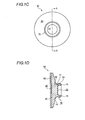
- FIG. 1C is a plan view of one embodiment of the male assembly of the fastener.
- FIG. 1D is a cross-sectional view taken along line A-A shown in FIG. 1C .
- FIG. 2A is a front perspective view of one embodiment of a stud according to the male assembly shown in FIGS. 1 A-D .
- FIG. 2B is a rear perspective view of one embodiment of the stud according to the male assembly shown in FIGS. 1A-D .
- FIG. 2C is a side view of one embodiment of the stud according to the male assembly shown in FIGS. 1A-D .
- FIG. 2D is a plan view of one embodiment of the stud according to the male assembly shown in FIGS. 1A-D .
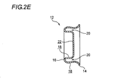
- FIG. 2E is a cross-sectional view taken along line B-B shown in FIG. 2D .
- FIG. 3A is a perspective view of one embodiment of a female assembly of a fastener.
- FIG. 3B is a side view of one embodiment of the female assembly of the fastener.
- FIG. 3C is a plan view of one embodiment of the female assembly of the fastener.
- FIG. 3D is a cross-sectional view taken along line C-C shown in FIG. 3C .
- FIG. 4A is a rear perspective view of one embodiment of a socket according to the female assembly shown in FIGS. 3A-D .
- FIG. 4B is a front perspective view of one embodiment of the stud according to the male assembly shown in FIGS. 3A-D .
- FIG. 4C is a side view of one embodiment of the stud according to the male assembly shown in FIGS. 3A-D .
- FIG. 4D is a plan view of one embodiment of the stud according to the male assembly shown in FIGS. 3A-D .
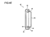
- FIG. 4E is a cross-sectional view taken along line D-D shown in FIG. 4D .
- FIG. 5 is a cross-sectional view of a fastener comprising a male assembly and a female assembly according to certain embodiments.
- FIG. 6 illustrates a male assembly secured to a non-planar mounting surface according to certain embodiments.
- FIG. 7 illustrates a female assembly secured to a non-planar mounting surface according to certain embodiments.
- FIG. 8 is a graph showing test results performed on a male assembly according to certain embodiments.
- FIG. 9 is a graph showing test results performed on a product as described by Demedash.
- the male assembly 10 may include a stud 12 (as shown in FIGS. 2A-E ) comprising a protrusion 16 extending from a base 14.
- the base 14 is generally planar.
- the protrusion 16 is shaped into a ring continuously extending in a circumferential direction, but it should be understood that in other embodiments, the protrusion 16 may have other shapes, and may or may not be continuous.
- the protrusion 16 may be defined by a sidewall 18. As shown in FIG.
- the cross-section of the sidewall 18 is generally "U-shaped" (although the sidewall 18 is not necessarily symmetrical) and defines a pocket 20 inside the U-shaped sidewall 18, such that the protrusion 16 is "hollow.”
- the pocket 20 also continuously extends in the circumferential direction.
- a central surface 22 is positioned in the middle of the ring-shaped protrusion 16. The central surface 22 is recessed from the protrusion 16 and the recess thereof is defined by inner surface of the sidewall 18 and the central surface 22.
- the female assembly 40 may include a socket 42 (as shown in FIGS. 4A-E ) comprising a receiving portion 46 and a base portion 44.
- the receiving portion 46 has a larger diameter than the base portion 44.
- the receiving portion 46 extends from the base portion 44 and is defined by a sidewall 52.
- a corner 48 is formed where the base portion 44 and the receiving portion 46 meet (at the border portion).
- the receiving portion 46 and the base portion 44 are both circular, but it should be understood that in other embodiments, the respective portions 44, 46 may have other shapes.
- the base portion 44 has a bottom surface 50 that is generally planar.
- the receiving portion 46 of the socket 42 receives and secures the protrusion 16 of the stud 12 with a mechanical interference fit, thus engaging the stud 12 and the socket 42, preventing separation of the fastener 100.
- the receiving portion 46 comprises a retainer 54 proximate the inner surface of the sidewall 52.
- the retainer 54 may have a ring shape by forming a wire into a ring.
- the outer diameter of the retainer 54 is smaller than a diameter of the inner surface of the receiving portion 46 and the inner diameter of the retainer 54 is smaller than a diameter of the outer surface of the stud 12, such that the retainer 54 may provide a more secure mechanical interference fit with the protrusion 16 of the stud 12 (the stud 12 fits into the receiving portion 46 and elastically expands the diameter of the retainer 54, and thereafter, the retainer 54 elastically return so that the protrusion 16 of the stud 12 engages with the retainer 54).
- the retainer 54 is only optional and is not required.
- the retainer 54 is not necessarily ring-shaped and it should be understood that the retainer 54 may have other shapes so as to conform to the shape of the receiving portion 46 or the base portion 44.
- the stud 12 and/or the socket 42 may be formed of a variety of materials, such as metals (including but not limited to stainless steel) or any rigid or semi-rigid plastic. If made of metal, the stud 12 and socket 42 may be stamped into their final forms. If made of plastic, the stud 12 and socket 42 may be injection die molded.
- the stud 12 is coupled to a flexible base 30 to form a male assembly 10 (as shown in FIGS. 1A-D ).
- the socket 42 is coupled to a flexible base 60 to form a female assembly 40 (as shown in FIGS. 3A-D ).
- Each flexible base 30, 60 may flex to conform to a non-planar mounting surface 110.
- the flexible base 30, 60 may be made of material more flexible than the stud 12 and the socket 42.
- the flexible base 30 of the male assembly 10 is flexed to conform to the non-planar (curved) mounting surface 110 (here, a section of pipe).
- An adhesive layer 36 on the bottom surface 32 of the flexible base 30 secures the male assembly 10 to the mounting surface 110.
- the flexible base 60 of the female assembly 40 is flexed to conform to the mounting surface 110.
- An adhesive layer 66 on the bottom surface 62 of the flexible base 60 secures the female assembly 40 to the mounting surface 110. It should be understood that it is not necessary for a single fastener 100 to include both a male and female assembly 10, 40 with a flexible base 30, 60. Rather, a fastener 100 may be provided with only one assembly (either the male assembly 10 or female assembly 40) that includes a flexible base.
- the stud 12 is pre-treated with a bonding or priming agent in order to help strengthen the bond between the stud 12 and the flexible base 30.
- a bonding or priming agent is a dilute solution of moisture-reactive materials in VM&P naphtha.
- the Dow-Corning Company produces such a material, under the name of Dow-Corning Prime Coat #2260.
- the stud 12 is treated with the bonding agent for at least fifteen minutes, after which time the excess bonding agent is drained or wiped clean from the stud 12.
- the flexible base 30 may be made of silicone, rubber, or any flexible plastic.
- the flexible base 30 is made from a blend of Dow-Corning TR-70 and Q-44768 elastomer materials, with their specific ratios being adjustable depending upon the specific application.
- a catalyst may be used to form the flexible base 30.
- One possible catalyst is an organic peroxide, which may be provided in different forms depending upon whether the flexible base 30 is clear or tinted.
- the catalyst may be an organic 100% peroxide in liquid form, having the chemical composition 2,5 dimethyl-2,5 di/t-butylperoxy/hexane.
- the above catalyst may be provided in only a 50% peroxide powder form.
- Either of the above catalysts may be supplied by Dow-Corning Company, as DBPH-100 for clear elastomers, or as DBPH-50 for colored or tinted elastomers.
- Alternative catalytic agents include platinum and tin compounds.
- the material that comprises the flexible base 30 may be bonded to the stud 12.
- a suitable container or holder similar to a mold
- the mold may have a "stud portion" to receive the stud 12, and a "base portion” that is shaped to form the flexible base 30.
- the base portion may have a profile that forms a flexible base 30 with a particular shape or size. For example, as shown in FIG. 1D , the top surface of the flexible base 30 is angled relative to the stud 12 and the thickness of the flexible base 30, which is defined between the top surface and the bottom surface 32 gets thinner toward the outer side.
- the base portion of the mold may have a profile to produce this particular angle.
- the flexible base 30 may have a different angle, may not be angled, or may be dome-shaped, etc.
- the mold may produce a flexible base 30 having any desired shape or size.
- the stud 12 may be placed inside of the stud portion of the mold, with the base 14 of the stud 12 facing the base portion of the mold.
- the material that comprises the flexible base 30 may be placed directly on top of the base 14 of the stud 12, within the base portion of the mold.
- a heated plate or the like may be placed atop the material that comprises the flexible base 30, and pressure may be applied to the plate to press the material onto the stud 12.
- the curing temperature is approximately 340° F, and the plate is left in place for approximately two minutes.
- the heat and pressure process causes the material that comprises the flexible base 30 to melt. The melted material flows within the base portion of the mold, forming the particular shape of the flexible base 30.
- the stud 12 is provided with pockets 20, then the melted material may flow into the pockets 20, forming extensions 34 to fill the pocket 20. The heat and pressure thus bond the flexible base 30 to the stud 12, forming the male assembly 10. Next, the plate may be removed from the male assembly 10 and excess material that comprises the flexible base 30 may be trimmed.
- the extensions 34 may have a ring shape continuously extending in the circumferential direction and fit into the pocket 20 (the inside of the sidewall 18). The extensions 34 are positioned in the middle of the circular-shaped male assembly 10 and protrude from the flexible base 30.
- An adhesive layer 36 may be affixed to the bottom surface 32 of the flexible base 30 to thereby secure the male assembly 10 to the mounting surface 110.
- the adhesive may comprise either a non-reactive adhesive or a reactive adhesive.
- the type of adhesive to be used may be determined by the size of the substrate and/or the mounting surface 110.
- One of skill in the art would be aware of many suitable adhesives, but one non-limiting example is the VHB® Tape, sold by 3M Company, which is made with a layer of acrylic foam and a layer of adhesive.
- the VHB® Tape is offered with several adhesive types, including multi-purpose acrylic (that bonds to metals, glass, and high and medium surface energy plastics and paints), modified acrylic (that bonds to low surface energy plastics and paints, such as powder-coated paints), or low temperature appliable acrylic (that bonds down to 32° F).
- the VHB® Tape is also offered with several foam types, each having different levels of conformability.
- the bottom surface 32 of the flexible base 30 may be pre-treated with a bonding agent, or may be mechanically deformed (such as with a sander) prior to application of the adhesive 36.
- the adhesive 36 may simply be pressed onto the bottom surface 32 of the flexible base 30 under atmospheric temperature and pressure.
- the socket 42 is provided with a corner 48 where the base portion 44 and the receiving portion 46 meet.
- the material that comprises the flexible base 60 melts due to the application of heat and pressure, the material flows around the base portion 44, into the corner 48, and around at least a portion of the receiving portion 46 (i.e. a portion at the outer surface of the receiving portion 46 with respect to the dimension of the flexible base in a front and rear direction).
- the amount of surface area between the flexible base 60 and the socket 42 (specifically, around the base portion 44, the corner 48, and at least a portion of the receiving portion 46) provides increased shear strength for the female assembly 40.
- the shear strength indicates the durability against drawing of the socket 40 in a direction along the front and rear direction of the flexible base 60.
- points of failure means that the components separate or break apart at that point.
- the fastener 100 failed between the adhesive 36 and the mounting surface 110, it means that the adhesive 36 pulled or ripped away from the mounting surface 110.
- the force that will cause a failure is significantly greater than the force of engaging and disengaging the fastener 100.
- fastener will not fail when it is engaged and disengaged, and in particular, that the fastener will not fail over repeated cycles. It has been found that embodiments of fasteners 100 described herein provide increased strength at each of these points of failure.
- the STICK A STUD® product (which is allegedly a commercialized embodiment of Demedash) and a product according to certain embodiments described herein (the "applicant's product”) were compared in strength tests.
- an Instron Model 4444 force gauge (hereinafter, "Instron") was used in a direct pull strength test of both the STICK A STUD® product and the applicant's product. The testing configuration for both products was the same.
- the male assembly of the fastener (the female assembly was not tested) was secured to a rod.
- the upper clap fixture of the Instron was used to clamp the stud of the male assembly. Each assembly was pulled by the Instron over known distances, as reflected in FIG.
- FIG. 8 Pull strength test results of the applicant's product
- FIG. 9 Pull strength test results of the STICK A STUD® product
- the black triangles on each Figure indicate the points that the respective product failed.
- the applicant's product was pulled a distance of approximately 0.3 inches before it failed at a load of 30.8 pounds of force (lbf).
- the STICK A STUD® product was only pulled a distance of approximately 0.08 inches before it failed at a load of 11.6 pounds of force (lbf).
- the test results also highlight differences between the designs of the two products.
- the point of failure was between the adhesive 36 and the mounting surface 110.
- the point of failure was between the post of the flexible mounting member and the aperture defined in the fastener.
- a point of failure between the adhesive 36 and the mounting surface 110 (as in the applicant's product) is preferred such that no part of the male assembly 10 is left behind on the mounting surface 110.
- the flexible mounting member was left secured to the mounting surface. Leaving components secured to the mounting surface is undesirable because those components must be removed, which may be difficult.
Landscapes
- Snaps, Bayonet Connections, Set Pins, And Snap Rings (AREA)
- Connection Of Plates (AREA)
- Standing Axle, Rod, Or Tube Structures Coupled By Welding, Adhesion, Or Deposition (AREA)
- Slide Fasteners, Snap Fasteners, And Hook Fasteners (AREA)
Abstract
Description
- The invention relates generally to fasteners that may be secured to mounting surfaces, and in particular, fasteners comprising a flexible base that may be secured to non-planar surfaces and that offer increased strength over known fasteners.
- In a variety of applications, it may be desirable to provide a fastener that can secure a first and second object together. Examples of objects may include a surface of a boat (such as the hull), a vehicle (such as the grill, hood, or cargo area of an automobile), or a hot tub or pool located on a deck or patio. Other examples may include fabric covers, tarps, straps, or bars. Thus, it may be desirable to provide a fastener to secure a cover to the grill of a vehicle, a tarp to the bed of a pick-up truck, or a cover to the hull of a boat.
- Such fasteners typically comprise a socket and a stud. The socket may include a base portion and a receiving portion protruding from the base. Likewise, the stud may include a base and a protrusion extending from the base. The receiving portion of the socket receives the protrusion of the stud, thus engaging the stud and the socket, preventing separation of the fastener. The socket may be secured to a mounting surface of a first object, and the stud may be secured to a mounting surface of the second object. As used herein, "mounting surface" refers to a surface of the object where the fastener is secured to the object. Thus, the socket may be coupled to the grill of a vehicle, and the stud may be coupled to the fabric cover. It should be understood that the fastener may be reversed, such that the stud is coupled to the grill and the socket is coupled to the fabric cover. For ease of reference, the background section of this disclosure refers to the stud and socket interchangeably as "a fastener component" unless otherwise noted.
- One technique for coupling the fastener component to the mounting surface involves drilling a hole in the mounting surface and using a screw to clamp the fastener component to the mounting surface. But this technique has a significant disadvantage of damaging the mounting surface by drilling a hole through the surface. Thus, alternative techniques have been developed to avoid damaging the mounting surface.
- One such alternative technique uses adhesives to secure the fastener component to the mounting surface. For example, the base of the fastener component (which typically has a planar surface) may be coated with a layer of adhesive and then secured to the mounting surface. It may be difficult to provide a strong bond if the mounting surface is curved or otherwise non-planar. Specifically, when coupled, there may be a gap between the planar base of the fastener component and the non-planar mounting surface. The gaps reduce the strength of the bond between the fastener component and the mounting surface. Thus, if the fastener is repeatedly engaged and disengaged over several cycles, then the fastener component may pull apart from the mounting surface. (It should be noted that the same difficulties may be encountered when welding—as opposed to adhering—the fastener component to the non-planar mounting surface.)
-
U.S. Patent No. 5,797,643 , which lists Lloyd Demedash as an inventor (hereinafter, "Demedash"), describes a fastener that purports to couple to non-planar mounting surfaces. Specifically, Demedash describes a "flexible mounting member" that is affixed to the fastener and that deforms to follow the curvature of a non-planar mounting surface. The flexible mounting member has a post that engages with an aperture defined in the fastener, thus securing the flexible mounting member to the fastener. Demedash teaches that the amount of force provided by the post (to secure the flexible mounting member and the fastener) is greater than the amount of force necessary to disengage the fastener (that is, to pull the socket from the stud). Thus, according to Demedash, the flexible mounting member will not detach when the fastener is repeatedly engaged and disengaged over several cycles. Demedash is assigned to FIA, Inc. of Winnipeg, Canada, which makes the STICK A STUD® product that is allegedly a commercialized embodiment of Demedash. - But the fastener described by Demedash (and the STICK A STUD® product) have several disadvantages. Most notably, tests performed on the STICK A STUD® product establish that the product fails when subjected to relatively low pull strengths. Additionally, the method of attachment between the flexible mounting member and the fastener requires specific design constraints that may be undesirable. Specifically, the post of the flexible mounting member requires that an aperture be provided in the fastener. It may not necessarily be desirable to provide a fastener with such an aperture. Finally, the post protrudes into the body of the fastener, which may obstruct proper engagement of the socket and stud.
- Thus, it is desirable to provide a male assembly, a female assembly and a fastener that couples to a non-planar mounting surface, but at the same time provides a high degree of strength prior to failure, withstands repeated engagement and disengagement of the fastener over several cycles, and also avoids limiting design constraints.
- Examples described herein include a male assembly for a fastener, the male assembly comprising a rigid stud that is bonded to a flexible base. A layer of adhesive may be provided on the flexible base to thereby secure the male assembly to a mounting surface. If the mounting surface is non-planar, then the flexible base may flex to conform to the non-planar mounting surface. Techniques used to bond the stud to the flexible base provide a high degree of strength to withstand repeated engagement and disengagement of the fastener. Moreover, the bonding techniques may eliminate the need for the post as provided in Demedash to secure the stud to the flexible base.
- Similarly, some examples include a female assembly comprising a rigid socket that is bonded to a flexible base that may flex to conform to a non-planar mounting surface. Bonding techniques provide a high degree of strength, and may eliminate the need for mechanical means to secure the socket to the flexible base. It is not necessary for a single fastener to include both a male assembly and a female assembly with a flexible base—only one of the assemblies may be provided with a flexible base.
- Mechanical tests performed on the male assembly show an increase of 62% in strength over the fastener described by Demedash.
- A full and enabling disclosure including the best mode of practicing the appended claims and directed to one of ordinary skill in the art is set forth more particularly in the remainder of the specification. The specification makes reference to the following appended figures, in which use of like reference numerals in different features is intended to illustrate like or analogous components.
-
FIG. 1A is a perspective view of one embodiment of a male assembly of a fastener.FIG. 1B is a side view of one embodiment of the male assembly of the fastener.FIG. 1C is a plan view of one embodiment of the male assembly of the fastener.FIG. 1D is a cross-sectional view taken along line A-A shown inFIG. 1C . -
FIG. 2A is a front perspective view of one embodiment of a stud according to the male assembly shown inFIGS. 1 A-D .FIG. 2B is a rear perspective view of one embodiment of the stud according to the male assembly shown inFIGS. 1A-D .FIG. 2C is a side view of one embodiment of the stud according to the male assembly shown inFIGS. 1A-D .FIG. 2D is a plan view of one embodiment of the stud according to the male assembly shown inFIGS. 1A-D .FIG. 2E is a cross-sectional view taken along line B-B shown inFIG. 2D . -
FIG. 3A is a perspective view of one embodiment of a female assembly of a fastener.FIG. 3B is a side view of one embodiment of the female assembly of the fastener.FIG. 3C is a plan view of one embodiment of the female assembly of the fastener.FIG. 3D is a cross-sectional view taken along line C-C shown inFIG. 3C . -
FIG. 4A is a rear perspective view of one embodiment of a socket according to the female assembly shown inFIGS. 3A-D .FIG. 4B is a front perspective view of one embodiment of the stud according to the male assembly shown inFIGS. 3A-D .FIG. 4C is a side view of one embodiment of the stud according to the male assembly shown inFIGS. 3A-D .FIG. 4D is a plan view of one embodiment of the stud according to the male assembly shown inFIGS. 3A-D .FIG. 4E is a cross-sectional view taken along line D-D shown inFIG. 4D . -
FIG. 5 is a cross-sectional view of a fastener comprising a male assembly and a female assembly according to certain embodiments. -
FIG. 6 illustrates a male assembly secured to a non-planar mounting surface according to certain embodiments. -
FIG. 7 illustrates a female assembly secured to a non-planar mounting surface according to certain embodiments. -
FIG. 8 is a graph showing test results performed on a male assembly according to certain embodiments. -
FIG. 9 is a graph showing test results performed on a product as described by Demedash. - Certain embodiments of the invention provide a
male assembly 10 and afemale assembly 40 that may be secured to one another in order to form a fastener 100 (as shown inFIG. 5 ). Themale assembly 10 may include a stud 12 (as shown inFIGS. 2A-E ) comprising aprotrusion 16 extending from abase 14. As can be seen inFIG. 2C , thebase 14 is generally planar. In the embodiments shown in the figures, theprotrusion 16 is shaped into a ring continuously extending in a circumferential direction, but it should be understood that in other embodiments, theprotrusion 16 may have other shapes, and may or may not be continuous. Theprotrusion 16 may be defined by asidewall 18. As shown inFIG. 2E , in some embodiments the cross-section of thesidewall 18 is generally "U-shaped" (although thesidewall 18 is not necessarily symmetrical) and defines apocket 20 inside theU-shaped sidewall 18, such that theprotrusion 16 is "hollow." Thepocket 20 also continuously extends in the circumferential direction. Acentral surface 22 is positioned in the middle of the ring-shapedprotrusion 16. Thecentral surface 22 is recessed from theprotrusion 16 and the recess thereof is defined by inner surface of thesidewall 18 and thecentral surface 22. - The
female assembly 40 may include a socket 42 (as shown inFIGS. 4A-E ) comprising a receivingportion 46 and abase portion 44. In the embodiments shown in the figures, the receivingportion 46 has a larger diameter than thebase portion 44. The receivingportion 46 extends from thebase portion 44 and is defined by asidewall 52. Acorner 48 is formed where thebase portion 44 and the receivingportion 46 meet (at the border portion). In the embodiments shown in the figures, the receivingportion 46 and thebase portion 44 are both circular, but it should be understood that in other embodiments, therespective portions FIG. 4C , thebase portion 44 has abottom surface 50 that is generally planar. - As shown in
FIG. 5 , the receivingportion 46 of thesocket 42 receives and secures theprotrusion 16 of thestud 12 with a mechanical interference fit, thus engaging thestud 12 and thesocket 42, preventing separation of thefastener 100. In certain embodiments, the receivingportion 46 comprises aretainer 54 proximate the inner surface of thesidewall 52. Theretainer 54 may have a ring shape by forming a wire into a ring. The outer diameter of theretainer 54 is smaller than a diameter of the inner surface of the receivingportion 46 and the inner diameter of theretainer 54 is smaller than a diameter of the outer surface of thestud 12, such that theretainer 54 may provide a more secure mechanical interference fit with theprotrusion 16 of the stud 12 (thestud 12 fits into the receivingportion 46 and elastically expands the diameter of theretainer 54, and thereafter, theretainer 54 elastically return so that theprotrusion 16 of thestud 12 engages with the retainer 54). It should be understood that theretainer 54 is only optional and is not required. Theretainer 54 is not necessarily ring-shaped and it should be understood that theretainer 54 may have other shapes so as to conform to the shape of the receivingportion 46 or thebase portion 44. - The
stud 12 and/or thesocket 42 may be formed of a variety of materials, such as metals (including but not limited to stainless steel) or any rigid or semi-rigid plastic. If made of metal, thestud 12 andsocket 42 may be stamped into their final forms. If made of plastic, thestud 12 andsocket 42 may be injection die molded. - In certain embodiments, the
stud 12 is coupled to aflexible base 30 to form a male assembly 10 (as shown inFIGS. 1A-D ). Similarly, in certain embodiments thesocket 42 is coupled to aflexible base 60 to form a female assembly 40 (as shown inFIGS. 3A-D ). Eachflexible base surface 110. Theflexible base stud 12 and thesocket 42. Thus, as shown inFIG. 6 , theflexible base 30 of themale assembly 10 is flexed to conform to the non-planar (curved) mounting surface 110 (here, a section of pipe). Anadhesive layer 36 on thebottom surface 32 of theflexible base 30 secures themale assembly 10 to the mountingsurface 110. Similarly, inFIG. 7 , theflexible base 60 of thefemale assembly 40 is flexed to conform to the mountingsurface 110. Anadhesive layer 66 on thebottom surface 62 of theflexible base 60 secures thefemale assembly 40 to the mountingsurface 110. It should be understood that it is not necessary for asingle fastener 100 to include both a male andfemale assembly flexible base fastener 100 may be provided with only one assembly (either themale assembly 10 or female assembly 40) that includes a flexible base. - Methods of manufacturing the male and
female assemblies male assembly 10, although it should be understood that the same general methods may be used for thefemale assembly 40. - First, the
stud 12 is pre-treated with a bonding or priming agent in order to help strengthen the bond between thestud 12 and theflexible base 30. One such bonding agent is a dilute solution of moisture-reactive materials in VM&P naphtha. The Dow-Corning Company produces such a material, under the name of Dow-Corning Prime Coat #2260. In certain embodiments thestud 12 is treated with the bonding agent for at least fifteen minutes, after which time the excess bonding agent is drained or wiped clean from thestud 12. - In general, the
flexible base 30 may be made of silicone, rubber, or any flexible plastic. In one non-limiting embodiment, theflexible base 30 is made from a blend of Dow-Corning TR-70 and Q-44768 elastomer materials, with their specific ratios being adjustable depending upon the specific application. If desired, a catalyst may be used to form theflexible base 30. One possible catalyst is an organic peroxide, which may be provided in different forms depending upon whether theflexible base 30 is clear or tinted. For a clearflexible base 30, the catalyst may be an organic 100% peroxide in liquid form, having thechemical composition 2,5 dimethyl-2,5 di/t-butylperoxy/hexane. For a tintedflexible base 30, the above catalyst may be provided in only a 50% peroxide powder form. Either of the above catalysts may be supplied by Dow-Corning Company, as DBPH-100 for clear elastomers, or as DBPH-50 for colored or tinted elastomers. Alternative catalytic agents include platinum and tin compounds. When the catalyzing process has been completed, the material that comprises theflexible base 30 will be in the form of a resilient solid. In certain embodiments, the material is formed in sheets. If desired, multiple layers or thicknesses may be used to create themale assembly 10. - Next, the material that comprises the
flexible base 30 may be bonded to thestud 12. In one embodiment, a suitable container or holder (similar to a mold) may be provided to assist in the bonding process. If desired, the mold may have a "stud portion" to receive thestud 12, and a "base portion" that is shaped to form theflexible base 30. The base portion may have a profile that forms aflexible base 30 with a particular shape or size. For example, as shown inFIG. 1D , the top surface of theflexible base 30 is angled relative to thestud 12 and the thickness of theflexible base 30, which is defined between the top surface and thebottom surface 32 gets thinner toward the outer side. Thus, the base portion of the mold may have a profile to produce this particular angle. In other embodiments, theflexible base 30 may have a different angle, may not be angled, or may be dome-shaped, etc. The mold may produce aflexible base 30 having any desired shape or size. - The
stud 12 may be placed inside of the stud portion of the mold, with thebase 14 of thestud 12 facing the base portion of the mold. The material that comprises theflexible base 30 may be placed directly on top of thebase 14 of thestud 12, within the base portion of the mold. Next, a heated plate or the like may be placed atop the material that comprises theflexible base 30, and pressure may be applied to the plate to press the material onto thestud 12. In certain embodiments, the curing temperature is approximately 340° F, and the plate is left in place for approximately two minutes. The heat and pressure process causes the material that comprises theflexible base 30 to melt. The melted material flows within the base portion of the mold, forming the particular shape of theflexible base 30. If thestud 12 is provided withpockets 20, then the melted material may flow into thepockets 20, formingextensions 34 to fill thepocket 20. The heat and pressure thus bond theflexible base 30 to thestud 12, forming themale assembly 10. Next, the plate may be removed from themale assembly 10 and excess material that comprises theflexible base 30 may be trimmed. Theextensions 34 may have a ring shape continuously extending in the circumferential direction and fit into the pocket 20 (the inside of the sidewall 18). Theextensions 34 are positioned in the middle of the circular-shapedmale assembly 10 and protrude from theflexible base 30. - Due to the bonding of the
flexible base 30 and thestud 12, it is not necessary to provide a post in theflexible base 30 as described by Demedash. All of the bonding is accomplished by the application of heat and pressure, and if desired, pre-treating of thestud 12 with a bonding agent. Increased bonding strength (in particular, increased shear strength) may also be provided inembodiments having extensions 34 that fit within pockets 20. The shear strength indicates the durability against drawing of thestud 12 in a direction along a front and rear direction of theflexible base 30, i.e. generally in a horizontal direction with respect to the bonding surface between thesidewall 18 and theextensions 34. - An
adhesive layer 36 may be affixed to thebottom surface 32 of theflexible base 30 to thereby secure themale assembly 10 to the mountingsurface 110. The adhesive may comprise either a non-reactive adhesive or a reactive adhesive. The type of adhesive to be used may be determined by the size of the substrate and/or the mountingsurface 110. One of skill in the art would be aware of many suitable adhesives, but one non-limiting example is the VHB® Tape, sold by 3M Company, which is made with a layer of acrylic foam and a layer of adhesive. The VHB® Tape is offered with several adhesive types, including multi-purpose acrylic (that bonds to metals, glass, and high and medium surface energy plastics and paints), modified acrylic (that bonds to low surface energy plastics and paints, such as powder-coated paints), or low temperature appliable acrylic (that bonds down to 32° F). The VHB® Tape is also offered with several foam types, each having different levels of conformability. If desired, thebottom surface 32 of theflexible base 30 may be pre-treated with a bonding agent, or may be mechanically deformed (such as with a sander) prior to application of the adhesive 36. The adhesive 36 may simply be pressed onto thebottom surface 32 of theflexible base 30 under atmospheric temperature and pressure. That is, no heated platen and/or extreme pressures are needed to bond adhesive 36 to theflexible base 30. Similarly, no heated platen and/or extreme pressures are needed to bond the adhesive 36 to the mountingsurface 110. (If desired, adhesive may also be applied directly to the mountingsurface 110.) - Although the preceding discussion of the methods of manufacture referred to the
male assembly 10, it should be understood that the same methods may be used for thefemale assembly 40. In the embodiments shown inFIG. 3 , thesocket 42 is provided with acorner 48 where thebase portion 44 and the receivingportion 46 meet. When the material that comprises theflexible base 60 melts due to the application of heat and pressure, the material flows around thebase portion 44, into thecorner 48, and around at least a portion of the receiving portion 46 (i.e. a portion at the outer surface of the receivingportion 46 with respect to the dimension of the flexible base in a front and rear direction). The amount of surface area between theflexible base 60 and the socket 42 (specifically, around thebase portion 44, thecorner 48, and at least a portion of the receiving portion 46) provides increased shear strength for thefemale assembly 40. The shear strength indicates the durability against drawing of thesocket 40 in a direction along the front and rear direction of theflexible base 60. - When the
fastener 100 is secured to the mountingsurface 110 and put into use, there are three possible points of "failure" of the fastener—specifically, between (1) the adhesive 36 and the mountingsurface 110; (2) the adhesive 36 and thebottom surface 32 of theflexible base 30; and (3) thestud 12 and theflexible base 30. The term "point of failure" means that the components separate or break apart at that point. For example, if thefastener 100 failed between the adhesive 36 and the mountingsurface 110, it means that the adhesive 36 pulled or ripped away from the mountingsurface 110. In the optimal design of a fastener, the force that will cause a failure is significantly greater than the force of engaging and disengaging thefastener 100. In other words, it is desired that the fastener will not fail when it is engaged and disengaged, and in particular, that the fastener will not fail over repeated cycles. It has been found that embodiments offasteners 100 described herein provide increased strength at each of these points of failure. - Specifically, the STICK A STUD® product (which is allegedly a commercialized embodiment of Demedash) and a product according to certain embodiments described herein (the "applicant's product") were compared in strength tests. In one test, an Instron Model 4444 force gauge (hereinafter, "Instron") was used in a direct pull strength test of both the STICK A STUD® product and the applicant's product. The testing configuration for both products was the same. First, the male assembly of the fastener (the female assembly was not tested) was secured to a rod. Then the upper clap fixture of the Instron was used to clamp the stud of the male assembly. Each assembly was pulled by the Instron over known distances, as reflected in
FIG. 8 (pull strength test results of the applicant's product) andFIG. 9 (pull strength test results of the STICK A STUD® product). The black triangles on each Figure indicate the points that the respective product failed. As shown inFIG. 8 , the applicant's product was pulled a distance of approximately 0.3 inches before it failed at a load of 30.8 pounds of force (lbf). In contrast, the STICK A STUD® product was only pulled a distance of approximately 0.08 inches before it failed at a load of 11.6 pounds of force (lbf). These test results show that the applicant's product exhibits 62% higher strength than the STICK A STUD® product. - The test results also highlight differences between the designs of the two products. In the applicant's product, the point of failure was between the adhesive 36 and the mounting
surface 110. In the STICK A STUD® product, the point of failure was between the post of the flexible mounting member and the aperture defined in the fastener. A point of failure between the adhesive 36 and the mounting surface 110 (as in the applicant's product) is preferred such that no part of themale assembly 10 is left behind on the mountingsurface 110. For example, because the STICK A STUD® product failed between the flexible mounting member and the fastener, the flexible mounting member was left secured to the mounting surface. Leaving components secured to the mounting surface is undesirable because those components must be removed, which may be difficult. - The foregoing is provided for purposes of illustration and disclosure of embodiments of the invention. It will be appreciated that those skilled in the art, upon attaining an understanding of the foregoing may readily produce alterations to, variations of, and equivalents to such embodiments. Accordingly, it should be understood that the present disclosure has been presented for purposes of example rather than limitation, and does not preclude inclusion of such modifications, variations and/or additions to the present subject matter as would be readily apparent to one of ordinary skill in the art.
Claims (15)
- A male assembly for a fastener, the male assembly comprising:a stud comprising at least one protrusion defined by a sidewall and at least one pocket defined by an inner surface of the sidewall; anda flexible base bonded to the stud, the flexible base comprising at least one extension that fits within and bonds to the at least one pocket of the stud,wherein the flexible base can flex to conform to a non-planar mounting surface.
- A male assembly as in claim 1, wherein the sidewall is approximately U-shaped, and the at least one pocket is defined by the inner surface of the U-shaped sidewall.
- A male assembly as in claim 1, wherein the at least one protrusion is a ring-shaped protrusion that extends continuously around the stud.
- A male assembly as in claim 3, wherein the at least one extension is a ring-shaped extension that extends continuously around the flexible base.
- A male assembly as in claim 1, further comprising an adhesive layer affixed to the flexible base for securing the male assembly to the mounting surface.
- A male assembly as in claim 1, wherein the male assembly withstands a load of up to approximately 31 lbf prior to failure.
- A female assembly for a fastener, the female assembly comprising:a socket comprising a base portion and a receiving portion extending from the base portion, wherein a corner is defined between the base portion and the receiving portion; anda flexible base bonded to the socket, wherein the flexible base contacts the base portion, the corner, and at least a portion of the receiving portion,wherein the flexible base is flexible to conform to a non-planar mounting surface.
- A female assembly as in claim 7, wherein each of the base portion and receiving portion of the socket are circular.
- A female assembly as in claim 7, wherein the flexible base contacts the base portion, the corner, and the portion of the receiving portion.
- A female assembly as in claim 7, further comprising an adhesive layer affixed to the flexible base for securing the female assembly to the mounting surface.
- A fastener comprising:a male assembly comprising a stud and a mounting member bonded to the stud, the stud comprising at least one protrusion defmed by a sidewall and at least one pocket defined by an inner surface of the sidewall, wherein a portion of the mounting member fits within and bonds to the at least one pocket of the stud; anda female assembly comprising a socket and a mounting member bonded to the socket, the socket comprising a receiving portion to receive the protrusion of the stud and thereby engage the female assembly to the male assembly,wherein the mounting member of the male assembly is flexible to conform to a non-planar mounting surface.
- A fastener as in claim 11, wherein the male assembly withstands a load of up to approximately 31 lbf prior to failure.
- A fastener as in claim 11, further comprising a layer of adhesive affixed to at least one of the mounting member of the male assembly or the mounting member of the female assembly.
- A fastener as in claim 11, wherein the mounting member of the female assembly is flexible to conform to a non-planar mounting surface.
- A fastener as in claim 11, wherein the socket further comprises a base portion and a corner defined between the base portion and the receiving portion, and wherein the mounting member of the female assembly contacts the base portion, the corner, and at least a portion of the receiving portion.
Applications Claiming Priority (1)
| Application Number | Priority Date | Filing Date | Title |
|---|---|---|---|
| US12/884,554 US8561269B2 (en) | 2010-09-17 | 2010-09-17 | Fastener having a flexible base |
Publications (2)
| Publication Number | Publication Date |
|---|---|
| EP2430943A1 true EP2430943A1 (en) | 2012-03-21 |
| EP2430943B1 EP2430943B1 (en) | 2013-01-09 |
Family
ID=44650875
Family Applications (1)
| Application Number | Title | Priority Date | Filing Date |
|---|---|---|---|
| EP11007538A Active EP2430943B1 (en) | 2010-09-17 | 2011-09-15 | Male assembly, female assembly and fastener |
Country Status (5)
| Country | Link |
|---|---|
| US (1) | US8561269B2 (en) |
| EP (1) | EP2430943B1 (en) |
| JP (1) | JP5780881B2 (en) |
| CN (1) | CN102434556B (en) |
| WO (1) | WO2012037300A1 (en) |
Cited By (2)
| Publication number | Priority date | Publication date | Assignee | Title |
|---|---|---|---|---|
| FR3019717A1 (en) * | 2014-04-14 | 2015-10-16 | Sandrine Tarrazi | SIMPLIFIED PRESSURE BUTTON INSTALLATION SYSTEM WITHOUT DRILLING, WITHOUT TOOLS FOR CLOTHING AND FURNITURE DECORATION |
| IT202300019380A1 (en) * | 2023-09-20 | 2025-03-20 | Murassi Ltd | ADHESIVE BUTTON |
Families Citing this family (25)
| Publication number | Priority date | Publication date | Assignee | Title |
|---|---|---|---|---|
| US9602640B1 (en) * | 2015-04-07 | 2017-03-21 | Donald Matt Ham | Adhesive hooks for releasably securing an earpiece to a mobile phone |
| US10064441B1 (en) * | 2016-02-12 | 2018-09-04 | Boston Inventions, LLC | Locking button system |
| CN109890239B (en) * | 2016-10-28 | 2021-11-16 | Ykk株式会社 | Convex part of snap fastener and snap fastener |
| CN116729803B (en) | 2017-06-12 | 2026-06-09 | 野醍冷却器有限责任公司 | Container and latch assembly |
| US11976498B2 (en) | 2017-06-12 | 2024-05-07 | Yeti Coolers, Llc | Container and latching system |
| AU201717615S (en) | 2017-06-12 | 2018-01-15 | Yeti Coolers | Container |
| US12108853B2 (en) | 2019-01-06 | 2024-10-08 | Yeti Coolers, Llc | Luggage system |
| US11685573B2 (en) | 2017-06-12 | 2023-06-27 | Yeti Coolers, Llc | Carry strap for container |
| JP6942038B2 (en) * | 2017-12-05 | 2021-09-29 | 日本航空電子工業株式会社 | connector |
| USD904829S1 (en) | 2018-12-11 | 2020-12-15 | Yeti Coolers, Llc | Container accessories |
| USD907445S1 (en) | 2018-12-11 | 2021-01-12 | Yeti Coolers, Llc | Container accessories |
| JP7303313B2 (en) | 2019-01-06 | 2023-07-04 | イエティ クーラーズ エルエルシー | luggage system |
| US12225993B2 (en) | 2019-01-06 | 2025-02-18 | Yeti Coolers, Llc | Luggage system |
| US11219284B2 (en) | 2019-05-17 | 2022-01-11 | Ykk Corporation Of America | Snap button assembly |
| WO2021102550A1 (en) * | 2019-11-29 | 2021-06-03 | Incour Innovations Ltd. | Snap fastener and snap strap fastener for clothing |
| USD961926S1 (en) | 2020-06-30 | 2022-08-30 | Yeti Coolers, Llc | Luggage |
| USD954436S1 (en) | 2020-06-30 | 2022-06-14 | Yeti Coolers, Llc | Luggage |
| USD963344S1 (en) | 2020-06-30 | 2022-09-13 | Yeti Coolers, Llc | Luggage |
| USD951643S1 (en) | 2020-06-30 | 2022-05-17 | Yeti Coolers, Llc | Luggage |
| USD985937S1 (en) | 2020-12-16 | 2023-05-16 | Yeti Coolers, Llc | Container |
| USD960648S1 (en) | 2020-12-16 | 2022-08-16 | Yeti Coolers, Llc | Container accessory |
| USD994438S1 (en) | 2020-12-16 | 2023-08-08 | Yeti Coolers, Llc | Container |
| USD1027612S1 (en) * | 2021-04-07 | 2024-05-21 | Peter Jon Rubenzer | Load carrying holder |
| USD1044476S1 (en) * | 2022-03-04 | 2024-10-01 | Magever Co., Ltd. | Magnet mount |
| EP4473855A1 (en) * | 2023-06-09 | 2024-12-11 | Ann DesRuisseaux | Adhesive fabric fastener |
Citations (4)
| Publication number | Priority date | Publication date | Assignee | Title |
|---|---|---|---|---|
| FR2218851A1 (en) * | 1973-02-22 | 1974-09-20 | Raymond A Ste | |
| FR2747276A1 (en) * | 1996-04-15 | 1997-10-17 | Schaeffer Prym | Female part of press stud with spring |
| US5797643A (en) | 1996-01-19 | 1998-08-25 | Fia Inc. | Fastening a fabric cover to a vehicle surface |
| US20090293239A1 (en) * | 2005-05-23 | 2009-12-03 | Reinhold Stumpfl | Connecting device |
Family Cites Families (36)
| Publication number | Priority date | Publication date | Assignee | Title |
|---|---|---|---|---|
| US1451612A (en) * | 1921-10-19 | 1923-04-10 | Ben Z Hausner | Attaching means for separable fastener elements |
| US1904122A (en) * | 1932-08-20 | 1933-04-18 | Scovill Manufacturing Co | Detachable snap fastener for articles to be laundered |
| US2648614A (en) * | 1950-10-27 | 1953-08-11 | Crown Zellerbach Corp | Pressure sensitive adhesive sheet material |
| US2745159A (en) | 1951-03-30 | 1956-05-15 | United Carr Fastener Corp | Heat sealable plastic fastener and assembly |
| US2683908A (en) * | 1952-04-05 | 1954-07-20 | Scovill Manufacturing Co | Three-part snap fastener, including a detachable button element |
| US3010169A (en) * | 1958-02-24 | 1961-11-28 | Scovill Manufacturing Co | Garment detachable snap fasteners |
| US3107409A (en) | 1959-12-09 | 1963-10-22 | Raymond A | Snap fastener socket |
| US3243858A (en) | 1964-05-08 | 1966-04-05 | United Carr Inc | Fastener components adapted for electronic heat sealing |
| DE1262059B (en) * | 1965-02-17 | 1968-02-29 | Prym Werke William | Snap fastener part |
| FR2095282B1 (en) * | 1970-06-16 | 1976-04-16 | Parera Pedro | |
| US3750938A (en) * | 1971-01-13 | 1973-08-07 | R Wiseman | Plastic closure for paper containers and metho of making same |
| US3965952A (en) * | 1972-11-13 | 1976-06-29 | Eastern Poly Packaging Company | Plastic snap fastener |
| US3882853A (en) | 1973-02-15 | 1975-05-13 | Cardiodynamics | Biomedical electrode |
| US3918140A (en) * | 1974-04-29 | 1975-11-11 | Anthony N Konstant | Snap-fastener setting tool |
| JPS5190644A (en) | 1975-02-03 | 1976-08-09 | ||
| JPS61136914U (en) * | 1985-02-14 | 1986-08-26 | ||
| GB2179994B (en) * | 1985-09-05 | 1988-12-29 | Kit Hart Metal Factory | Snap-type fastener |
| JPS62155805A (en) * | 1985-12-27 | 1987-07-10 | モリト株式会社 | Snap fastener and its production |
| JPH02271805A (en) * | 1989-04-12 | 1990-11-06 | Buaarei:Kk | Ornamental snap device |
| DE3918375A1 (en) * | 1989-06-06 | 1990-12-13 | Prym Werke William | PUSH BUTTON CONNECTION |
| JPH0384543A (en) | 1989-08-29 | 1991-04-10 | Brother Ind Ltd | Patrone containing microcapsule sheet |
| US5075938A (en) * | 1990-06-11 | 1991-12-31 | Hutchinson T Gordon | Fastening device |
| US5113553A (en) * | 1990-09-18 | 1992-05-19 | Hutchinson T Gordon | Fastening device |
| JP2561703Y2 (en) * | 1991-05-31 | 1998-02-04 | ワイケイケイ株式会社 | Snap button |
| JPH0641514U (en) | 1992-11-20 | 1994-06-03 | 吉田工業株式会社 | Snap button |
| JP3084543B2 (en) | 1993-09-22 | 2000-09-04 | シャープ株式会社 | Dewatering washing machine water seal device |
| US5475937A (en) * | 1994-05-25 | 1995-12-19 | Korsen; David L. | Shoe spike apparatus |
| US5956816A (en) | 1998-03-18 | 1999-09-28 | Mccrink; David J. | Elastomer coating for buttons, and method therefor |
| US6626122B2 (en) * | 2001-10-18 | 2003-09-30 | Chevron U.S.A. Inc | Deactivatable biocides in ballast water |
| US6718559B1 (en) * | 2002-01-31 | 2004-04-13 | Howard Davidson | Motorcycle helmut snap-on decorative device |
| AUPS312302A0 (en) * | 2002-06-19 | 2002-07-18 | Telezygology Inc | Further improvements in fixing and release systems |
| KR100403901B1 (en) * | 2003-06-07 | 2003-11-01 | Han Kee Jung | Snap button and die for coupling the same |
| JP3910963B2 (en) * | 2004-02-16 | 2007-04-25 | 株式会社ワンタッチ畜産資材研究所 | Animal ear tags |
| JP4449021B2 (en) * | 2006-06-29 | 2010-04-14 | 株式会社サトーゴーセー | Resin fixture |
| US8061898B2 (en) * | 2008-07-15 | 2011-11-22 | S.C. Johnson & Son, Inc. | Venting closure mechanism |
| JP5190644B2 (en) | 2008-09-24 | 2013-04-24 | 日本電産サンキョー株式会社 | Encoder error correction method |
-
2010
- 2010-09-17 US US12/884,554 patent/US8561269B2/en active Active
-
2011
- 2011-08-16 JP JP2011178000A patent/JP5780881B2/en active Active
- 2011-09-15 WO PCT/US2011/051674 patent/WO2012037300A1/en not_active Ceased
- 2011-09-15 EP EP11007538A patent/EP2430943B1/en active Active
- 2011-09-16 CN CN201110277331.6A patent/CN102434556B/en active Active
Patent Citations (4)
| Publication number | Priority date | Publication date | Assignee | Title |
|---|---|---|---|---|
| FR2218851A1 (en) * | 1973-02-22 | 1974-09-20 | Raymond A Ste | |
| US5797643A (en) | 1996-01-19 | 1998-08-25 | Fia Inc. | Fastening a fabric cover to a vehicle surface |
| FR2747276A1 (en) * | 1996-04-15 | 1997-10-17 | Schaeffer Prym | Female part of press stud with spring |
| US20090293239A1 (en) * | 2005-05-23 | 2009-12-03 | Reinhold Stumpfl | Connecting device |
Cited By (2)
| Publication number | Priority date | Publication date | Assignee | Title |
|---|---|---|---|---|
| FR3019717A1 (en) * | 2014-04-14 | 2015-10-16 | Sandrine Tarrazi | SIMPLIFIED PRESSURE BUTTON INSTALLATION SYSTEM WITHOUT DRILLING, WITHOUT TOOLS FOR CLOTHING AND FURNITURE DECORATION |
| IT202300019380A1 (en) * | 2023-09-20 | 2025-03-20 | Murassi Ltd | ADHESIVE BUTTON |
Also Published As
| Publication number | Publication date |
|---|---|
| HK1169696A1 (en) | 2013-02-01 |
| JP2012063010A (en) | 2012-03-29 |
| WO2012037300A1 (en) | 2012-03-22 |
| US20120066874A1 (en) | 2012-03-22 |
| EP2430943B1 (en) | 2013-01-09 |
| CN102434556B (en) | 2015-07-08 |
| CN102434556A (en) | 2012-05-02 |
| JP5780881B2 (en) | 2015-09-16 |
| US8561269B2 (en) | 2013-10-22 |
Similar Documents
| Publication | Publication Date | Title |
|---|---|---|
| EP2430943B1 (en) | Male assembly, female assembly and fastener | |
| US9039318B2 (en) | Component connection comprising a first and a second component and a male and a female fixing element | |
| CN101898590B (en) | Clip for attachment to at least one panel of a vehicle to support a molding | |
| EP2686223B1 (en) | Bonding assembly | |
| US8870272B2 (en) | Floor module for a motor vehicle having shaped-on formfitting means | |
| JPS62200009A (en) | Panel-fixing element support ferrule for interior panel consisting of substrate and foamed section | |
| EP0365637A1 (en) | A seal. | |
| WO2014061122A1 (en) | Nut having seal washer | |
| US9211861B2 (en) | Airbag deployment device | |
| US9435365B2 (en) | Rivet sealing washer | |
| US20100098515A1 (en) | Attachment fastener | |
| JPH0675927B2 (en) | Resin tank manufacturing method | |
| GB2360322A (en) | Improvements relating to fasteners | |
| JPH10318221A (en) | Engaging member provided with connecting element to support and attachment member provided with this engaging member | |
| EP3222493B1 (en) | Stitchless steering wheel fitted with leather | |
| HK1169696B (en) | Male assembly, female assembly and fastener | |
| JP4995630B2 (en) | Bonding method and bonding structure | |
| JP6065338B2 (en) | Vehicle window plate with frame and method of assembling vehicle window plate with frame | |
| CA2638891C (en) | Foam product having an accessory and method of making | |
| US8708344B2 (en) | Sealed assemblies and methods of unsealing same | |
| JP2012255497A (en) | Fixture and container for transportation | |
| JP2014128890A (en) | Seal structure | |
| CN214823041U (en) | Vehicle door outer decorative plate assembly | |
| JP6164677B2 (en) | Method of manufacturing ceiling interior member with duct | |
| CN109667821A (en) | Fastening device |
Legal Events
| Date | Code | Title | Description |
|---|---|---|---|
| PUAI | Public reference made under article 153(3) epc to a published international application that has entered the european phase |
Free format text: ORIGINAL CODE: 0009012 |
|
| 17P | Request for examination filed |
Effective date: 20110915 |
|
| AK | Designated contracting states |
Kind code of ref document: A1 Designated state(s): AL AT BE BG CH CY CZ DE DK EE ES FI FR GB GR HR HU IE IS IT LI LT LU LV MC MK MT NL NO PL PT RO RS SE SI SK SM TR |
|
| AX | Request for extension of the european patent |
Extension state: BA ME |
|
| GRAP | Despatch of communication of intention to grant a patent |
Free format text: ORIGINAL CODE: EPIDOSNIGR1 |
|
| GRAS | Grant fee paid |
Free format text: ORIGINAL CODE: EPIDOSNIGR3 |
|
| GRAA | (expected) grant |
Free format text: ORIGINAL CODE: 0009210 |
|
| AK | Designated contracting states |
Kind code of ref document: B1 Designated state(s): AL AT BE BG CH CY CZ DE DK EE ES FI FR GB GR HR HU IE IS IT LI LT LU LV MC MK MT NL NO PL PT RO RS SE SI SK SM TR |
|
| REG | Reference to a national code |
Ref country code: GB Ref legal event code: FG4D |
|
| REG | Reference to a national code |
Ref country code: AT Ref legal event code: REF Ref document number: 592238 Country of ref document: AT Kind code of ref document: T Effective date: 20130115 Ref country code: CH Ref legal event code: EP |
|
| REG | Reference to a national code |
Ref country code: IE Ref legal event code: FG4D |
|
| REG | Reference to a national code |
Ref country code: DE Ref legal event code: R096 Ref document number: 602011000671 Country of ref document: DE Effective date: 20130314 |
|
| PG25 | Lapsed in a contracting state [announced via postgrant information from national office to epo] |
Ref country code: SI Free format text: LAPSE BECAUSE OF FAILURE TO SUBMIT A TRANSLATION OF THE DESCRIPTION OR TO PAY THE FEE WITHIN THE PRESCRIBED TIME-LIMIT Effective date: 20130109 |
|
| REG | Reference to a national code |
Ref country code: NL Ref legal event code: VDEP Effective date: 20130109 |
|
| REG | Reference to a national code |
Ref country code: AT Ref legal event code: MK05 Ref document number: 592238 Country of ref document: AT Kind code of ref document: T Effective date: 20130109 |
|
| REG | Reference to a national code |
Ref country code: LT Ref legal event code: MG4D |
|
| PG25 | Lapsed in a contracting state [announced via postgrant information from national office to epo] |
Ref country code: NO Free format text: LAPSE BECAUSE OF FAILURE TO SUBMIT A TRANSLATION OF THE DESCRIPTION OR TO PAY THE FEE WITHIN THE PRESCRIBED TIME-LIMIT Effective date: 20130409 Ref country code: BG Free format text: LAPSE BECAUSE OF FAILURE TO SUBMIT A TRANSLATION OF THE DESCRIPTION OR TO PAY THE FEE WITHIN THE PRESCRIBED TIME-LIMIT Effective date: 20130409 Ref country code: BE Free format text: LAPSE BECAUSE OF FAILURE TO SUBMIT A TRANSLATION OF THE DESCRIPTION OR TO PAY THE FEE WITHIN THE PRESCRIBED TIME-LIMIT Effective date: 20130109 Ref country code: IS Free format text: LAPSE BECAUSE OF FAILURE TO SUBMIT A TRANSLATION OF THE DESCRIPTION OR TO PAY THE FEE WITHIN THE PRESCRIBED TIME-LIMIT Effective date: 20130509 Ref country code: AT Free format text: LAPSE BECAUSE OF FAILURE TO SUBMIT A TRANSLATION OF THE DESCRIPTION OR TO PAY THE FEE WITHIN THE PRESCRIBED TIME-LIMIT Effective date: 20130109 Ref country code: SE Free format text: LAPSE BECAUSE OF FAILURE TO SUBMIT A TRANSLATION OF THE DESCRIPTION OR TO PAY THE FEE WITHIN THE PRESCRIBED TIME-LIMIT Effective date: 20130109 Ref country code: LT Free format text: LAPSE BECAUSE OF FAILURE TO SUBMIT A TRANSLATION OF THE DESCRIPTION OR TO PAY THE FEE WITHIN THE PRESCRIBED TIME-LIMIT Effective date: 20130109 Ref country code: ES Free format text: LAPSE BECAUSE OF FAILURE TO SUBMIT A TRANSLATION OF THE DESCRIPTION OR TO PAY THE FEE WITHIN THE PRESCRIBED TIME-LIMIT Effective date: 20130420 |
|
| PG25 | Lapsed in a contracting state [announced via postgrant information from national office to epo] |
Ref country code: NL Free format text: LAPSE BECAUSE OF FAILURE TO SUBMIT A TRANSLATION OF THE DESCRIPTION OR TO PAY THE FEE WITHIN THE PRESCRIBED TIME-LIMIT Effective date: 20130109 Ref country code: FI Free format text: LAPSE BECAUSE OF FAILURE TO SUBMIT A TRANSLATION OF THE DESCRIPTION OR TO PAY THE FEE WITHIN THE PRESCRIBED TIME-LIMIT Effective date: 20130109 Ref country code: PL Free format text: LAPSE BECAUSE OF FAILURE TO SUBMIT A TRANSLATION OF THE DESCRIPTION OR TO PAY THE FEE WITHIN THE PRESCRIBED TIME-LIMIT Effective date: 20130109 Ref country code: GR Free format text: LAPSE BECAUSE OF FAILURE TO SUBMIT A TRANSLATION OF THE DESCRIPTION OR TO PAY THE FEE WITHIN THE PRESCRIBED TIME-LIMIT Effective date: 20130410 Ref country code: PT Free format text: LAPSE BECAUSE OF FAILURE TO SUBMIT A TRANSLATION OF THE DESCRIPTION OR TO PAY THE FEE WITHIN THE PRESCRIBED TIME-LIMIT Effective date: 20130509 Ref country code: LV Free format text: LAPSE BECAUSE OF FAILURE TO SUBMIT A TRANSLATION OF THE DESCRIPTION OR TO PAY THE FEE WITHIN THE PRESCRIBED TIME-LIMIT Effective date: 20130109 |
|
| PG25 | Lapsed in a contracting state [announced via postgrant information from national office to epo] |
Ref country code: RS Free format text: LAPSE BECAUSE OF FAILURE TO SUBMIT A TRANSLATION OF THE DESCRIPTION OR TO PAY THE FEE WITHIN THE PRESCRIBED TIME-LIMIT Effective date: 20130109 Ref country code: HR Free format text: LAPSE BECAUSE OF FAILURE TO SUBMIT A TRANSLATION OF THE DESCRIPTION OR TO PAY THE FEE WITHIN THE PRESCRIBED TIME-LIMIT Effective date: 20130109 |
|
| PG25 | Lapsed in a contracting state [announced via postgrant information from national office to epo] |
Ref country code: DK Free format text: LAPSE BECAUSE OF FAILURE TO SUBMIT A TRANSLATION OF THE DESCRIPTION OR TO PAY THE FEE WITHIN THE PRESCRIBED TIME-LIMIT Effective date: 20130109 Ref country code: EE Free format text: LAPSE BECAUSE OF FAILURE TO SUBMIT A TRANSLATION OF THE DESCRIPTION OR TO PAY THE FEE WITHIN THE PRESCRIBED TIME-LIMIT Effective date: 20130109 Ref country code: RO Free format text: LAPSE BECAUSE OF FAILURE TO SUBMIT A TRANSLATION OF THE DESCRIPTION OR TO PAY THE FEE WITHIN THE PRESCRIBED TIME-LIMIT Effective date: 20130109 Ref country code: CZ Free format text: LAPSE BECAUSE OF FAILURE TO SUBMIT A TRANSLATION OF THE DESCRIPTION OR TO PAY THE FEE WITHIN THE PRESCRIBED TIME-LIMIT Effective date: 20130109 Ref country code: SK Free format text: LAPSE BECAUSE OF FAILURE TO SUBMIT A TRANSLATION OF THE DESCRIPTION OR TO PAY THE FEE WITHIN THE PRESCRIBED TIME-LIMIT Effective date: 20130109 |
|
| PLBE | No opposition filed within time limit |
Free format text: ORIGINAL CODE: 0009261 |
|
| STAA | Information on the status of an ep patent application or granted ep patent |
Free format text: STATUS: NO OPPOSITION FILED WITHIN TIME LIMIT |
|
| PG25 | Lapsed in a contracting state [announced via postgrant information from national office to epo] |
Ref country code: CY Free format text: LAPSE BECAUSE OF FAILURE TO SUBMIT A TRANSLATION OF THE DESCRIPTION OR TO PAY THE FEE WITHIN THE PRESCRIBED TIME-LIMIT Effective date: 20130109 |
|
| 26N | No opposition filed |
Effective date: 20131010 |
|
| PG25 | Lapsed in a contracting state [announced via postgrant information from national office to epo] |
Ref country code: IT Free format text: LAPSE BECAUSE OF FAILURE TO SUBMIT A TRANSLATION OF THE DESCRIPTION OR TO PAY THE FEE WITHIN THE PRESCRIBED TIME-LIMIT Effective date: 20130109 |
|
| REG | Reference to a national code |
Ref country code: DE Ref legal event code: R097 Ref document number: 602011000671 Country of ref document: DE Effective date: 20131010 |
|
| PG25 | Lapsed in a contracting state [announced via postgrant information from national office to epo] |
Ref country code: MC Free format text: LAPSE BECAUSE OF FAILURE TO SUBMIT A TRANSLATION OF THE DESCRIPTION OR TO PAY THE FEE WITHIN THE PRESCRIBED TIME-LIMIT Effective date: 20130109 |
|
| REG | Reference to a national code |
Ref country code: IE Ref legal event code: MM4A |
|
| PG25 | Lapsed in a contracting state [announced via postgrant information from national office to epo] |
Ref country code: IE Free format text: LAPSE BECAUSE OF NON-PAYMENT OF DUE FEES Effective date: 20130915 |
|
| REG | Reference to a national code |
Ref country code: CH Ref legal event code: PL |
|
| PG25 | Lapsed in a contracting state [announced via postgrant information from national office to epo] |
Ref country code: SM Free format text: LAPSE BECAUSE OF FAILURE TO SUBMIT A TRANSLATION OF THE DESCRIPTION OR TO PAY THE FEE WITHIN THE PRESCRIBED TIME-LIMIT Effective date: 20130109 |
|
| PG25 | Lapsed in a contracting state [announced via postgrant information from national office to epo] |
Ref country code: MT Free format text: LAPSE BECAUSE OF FAILURE TO SUBMIT A TRANSLATION OF THE DESCRIPTION OR TO PAY THE FEE WITHIN THE PRESCRIBED TIME-LIMIT Effective date: 20130109 Ref country code: TR Free format text: LAPSE BECAUSE OF FAILURE TO SUBMIT A TRANSLATION OF THE DESCRIPTION OR TO PAY THE FEE WITHIN THE PRESCRIBED TIME-LIMIT Effective date: 20130109 |
|
| PG25 | Lapsed in a contracting state [announced via postgrant information from national office to epo] |
Ref country code: LU Free format text: LAPSE BECAUSE OF NON-PAYMENT OF DUE FEES Effective date: 20130915 Ref country code: LI Free format text: LAPSE BECAUSE OF NON-PAYMENT OF DUE FEES Effective date: 20140930 Ref country code: CH Free format text: LAPSE BECAUSE OF NON-PAYMENT OF DUE FEES Effective date: 20140930 Ref country code: MK Free format text: LAPSE BECAUSE OF FAILURE TO SUBMIT A TRANSLATION OF THE DESCRIPTION OR TO PAY THE FEE WITHIN THE PRESCRIBED TIME-LIMIT Effective date: 20130109 Ref country code: HU Free format text: LAPSE BECAUSE OF FAILURE TO SUBMIT A TRANSLATION OF THE DESCRIPTION OR TO PAY THE FEE WITHIN THE PRESCRIBED TIME-LIMIT; INVALID AB INITIO Effective date: 20110915 |
|
| REG | Reference to a national code |
Ref country code: FR Ref legal event code: PLFP Year of fee payment: 6 |
|
| REG | Reference to a national code |
Ref country code: FR Ref legal event code: PLFP Year of fee payment: 7 |
|
| REG | Reference to a national code |
Ref country code: FR Ref legal event code: PLFP Year of fee payment: 8 |
|
| PG25 | Lapsed in a contracting state [announced via postgrant information from national office to epo] |
Ref country code: AL Free format text: LAPSE BECAUSE OF FAILURE TO SUBMIT A TRANSLATION OF THE DESCRIPTION OR TO PAY THE FEE WITHIN THE PRESCRIBED TIME-LIMIT Effective date: 20130109 |
|
| PGFP | Annual fee paid to national office [announced via postgrant information from national office to epo] |
Ref country code: DE Payment date: 20190903 Year of fee payment: 9 Ref country code: FR Payment date: 20190815 Year of fee payment: 9 |
|
| REG | Reference to a national code |
Ref country code: DE Ref legal event code: R119 Ref document number: 602011000671 Country of ref document: DE |
|
| PG25 | Lapsed in a contracting state [announced via postgrant information from national office to epo] |
Ref country code: DE Free format text: LAPSE BECAUSE OF NON-PAYMENT OF DUE FEES Effective date: 20210401 Ref country code: FR Free format text: LAPSE BECAUSE OF NON-PAYMENT OF DUE FEES Effective date: 20200930 |
|
| PGFP | Annual fee paid to national office [announced via postgrant information from national office to epo] |
Ref country code: GB Payment date: 20250731 Year of fee payment: 15 |