EP2430902B1 - Umhüllungsvorrichtung - Google Patents
Umhüllungsvorrichtung Download PDFInfo
- Publication number
- EP2430902B1 EP2430902B1 EP10177082.4A EP10177082A EP2430902B1 EP 2430902 B1 EP2430902 B1 EP 2430902B1 EP 10177082 A EP10177082 A EP 10177082A EP 2430902 B1 EP2430902 B1 EP 2430902B1
- Authority
- EP
- European Patent Office
- Prior art keywords
- web
- roll
- feeder
- wrap apparatus
- stripper
- Prior art date
- Legal status (The legal status is an assumption and is not a legal conclusion. Google has not performed a legal analysis and makes no representation as to the accuracy of the status listed.)
- Active
Links
- 239000004033 plastic Substances 0.000 claims description 4
- 239000000835 fiber Substances 0.000 description 3
- 239000000463 material Substances 0.000 description 3
- 239000002184 metal Substances 0.000 description 2
- 238000005096 rolling process Methods 0.000 description 2
- 238000000926 separation method Methods 0.000 description 2
- 241000405070 Percophidae Species 0.000 description 1
- 229910000831 Steel Inorganic materials 0.000 description 1
- 238000013459 approach Methods 0.000 description 1
- 238000004140 cleaning Methods 0.000 description 1
- 230000000694 effects Effects 0.000 description 1
- -1 net Substances 0.000 description 1
- 210000001331 nose Anatomy 0.000 description 1
- 229920001778 nylon Polymers 0.000 description 1
- 230000002028 premature Effects 0.000 description 1
- 230000000284 resting effect Effects 0.000 description 1
- 230000035939 shock Effects 0.000 description 1
- 239000010959 steel Substances 0.000 description 1
- 239000010902 straw Substances 0.000 description 1
- 230000007704 transition Effects 0.000 description 1
- 238000011144 upstream manufacturing Methods 0.000 description 1
- 239000002023 wood Substances 0.000 description 1
Images

Classifications
-
- A—HUMAN NECESSITIES
- A01—AGRICULTURE; FORESTRY; ANIMAL HUSBANDRY; HUNTING; TRAPPING; FISHING
- A01F—PROCESSING OF HARVESTED PRODUCE; HAY OR STRAW PRESSES; DEVICES FOR STORING AGRICULTURAL OR HORTICULTURAL PRODUCE
- A01F15/00—Baling presses for straw, hay or the like
- A01F15/07—Rotobalers, i.e. machines for forming cylindrical bales by winding and pressing
- A01F15/071—Wrapping devices
- A01F15/0715—Wrapping the bale in the press chamber before opening said chamber
-
- B—PERFORMING OPERATIONS; TRANSPORTING
- B26—HAND CUTTING TOOLS; CUTTING; SEVERING
- B26F—PERFORATING; PUNCHING; CUTTING-OUT; STAMPING-OUT; SEVERING BY MEANS OTHER THAN CUTTING
- B26F3/00—Severing by means other than cutting; Apparatus therefor
- B26F3/02—Tearing
-
- A—HUMAN NECESSITIES
- A01—AGRICULTURE; FORESTRY; ANIMAL HUSBANDRY; HUNTING; TRAPPING; FISHING
- A01F—PROCESSING OF HARVESTED PRODUCE; HAY OR STRAW PRESSES; DEVICES FOR STORING AGRICULTURAL OR HORTICULTURAL PRODUCE
- A01F15/00—Baling presses for straw, hay or the like
- A01F15/07—Rotobalers, i.e. machines for forming cylindrical bales by winding and pressing
- A01F15/071—Wrapping devices
- A01F2015/0725—Film dispensers for film rollers in a satellite type wrapper, e.g. holding and tensioning means for the film roller
-
- Y—GENERAL TAGGING OF NEW TECHNOLOGICAL DEVELOPMENTS; GENERAL TAGGING OF CROSS-SECTIONAL TECHNOLOGIES SPANNING OVER SEVERAL SECTIONS OF THE IPC; TECHNICAL SUBJECTS COVERED BY FORMER USPC CROSS-REFERENCE ART COLLECTIONS [XRACs] AND DIGESTS
- Y10—TECHNICAL SUBJECTS COVERED BY FORMER USPC
- Y10T—TECHNICAL SUBJECTS COVERED BY FORMER US CLASSIFICATION
- Y10T225/00—Severing by tearing or breaking
- Y10T225/30—Breaking or tearing apparatus
- Y10T225/393—Web restrainer
Definitions
- This invention relates to a web wrap apparatus with a feeder and a separator provided with a separating edge, whereas the feeder and the separator are moveable relative to each other.
- EP 766 912 discloses a round baler having a net feed device, moveable between a waiting position and a feeding position and a knife for the net.
- the problem this invention is based on is seen in the fact, that occasionally fibers of the net or other material build up on the edge of the knife and avoid a clean cut of the net.
- stripper By using such a stripper, fibers or any other material sticking or hanging on the separating edge will be removed. Dimensions, location, the way the stripper is fixed, etc. can be selected such, that a stripping action is performed depending on the expected dirt to be removed.
- the stripper could be attached to the feeder fixed or moveable under a bias.
- a brush of Nylon fibers or the like working as a stripper has the advantage of being highly flexible and thus insensitive to varying dimensions, but would also have a stronger cleaning effect, since a brush consists of a multitude of strippers.
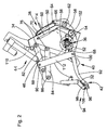
- FIG. 1 shows a round baler 10, which has a chassis 12, a pick-up 14, a bale chamber 16, a web wrap apparatus 18, an axle with wheels 20, a tongue 22 and pressing means 24.
- the round baler 10 is of ordinary kind in a fix chamber version, but could be a variable chamber baler, too.
- the chassis 12 rests on the axle with wheels 20, carries the pick-up 14 and can get connected to a tractor or the like by means of the tongue 22.
- the chassis 12 has substantially one or multiple part side walls 26, which are apart from each other to receive interbetween them the bale chamber 16, all or part of the web wrap apparatus 18 and the pressing means 24.
- the pick-up 14 picks up crop from the ground and delivers it to the bale chamber 16 through a crop inlet 28 between pressing means 24.
- the bale chamber 16 is covered substantially by the pressing means 24 on the circumference and by the side walls 26 on the face side. Beside the crop inlet 28 a gap 30 is provided between the pressing means 24, through which web 32 may be fed into the bale chamber 16.
- the bale chamber 16 serves to form a cylindrical bale of hay, straw or the like, which will be covered by the web 32 of plastic, net, paper or similar.
- the pressing means 24 in this embodiment are in the form of steel rolls rotatably received in the sidewalls 26 and extending perpendicular to them. These pressing means 24 are arranged on a circle.
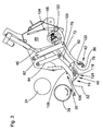
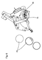
- the web wrap apparatus 18 is visible in more detail in figure 2 and contains among others a housing 34, a motion means 36, a brake device 38, a feeder 40, a separator 42 and an actuating mechanism 44.
- the housing 34 is located in the front upper part of the round baler 10 between or substantially between the side walls 26 and has a rear wall 46 and a left and a right wall 48 connected to each other and suitable to be connected to the side walls 26. Depending on the width of the web 32, the housing 34 and the entire web wrap apparatus 18 may extend beyond the side walls 26.
- the rear wall 46 may be of a material or may have a layer which creates a certain friction, which will have an influence on the rolling resistance of a roll 50 of the web 32.
- the housing 34 may be used to attach all components and parts of the web wrap apparatus 18 to it to form an autonomous unit.
- the right and left walls 48 extend to the rear towards the bale chamber 16 as is needed to take up some of the parts described later.
- the motion means 36 is formed by a roll 52, preferably rubber coated, which is journalled rotatably about a horizontal axis in walls 48 and which is located such, that the roll 50 of the web 32 can rest on it.
- a yieldable clutch 54 which may be a slip clutch, a rubber block between a flange and the roll 52 or similar.
- Said clutch 54 has several - in this case three - actuators 56 evenly distributed on the circumference of a disc rotating with it; yet one would be sufficient.
- Said actuators 56 may be stops, noses, or the like protruding radially, but it may also be grooves or notches in the circumference.
- the roll 52 has about the same diameter as the clutch 54.
- roll 52 is connected via a chain drive and a free-wheel to the pressing means 24 such, that it must rotate slower than the pressing means 24.
- the brake device 38 substantially has a control arm 58 and a brake arm 60 connected together in a shaft 62 to pivot about a horizontal axis of latter. Also a gas spring 64 is connected to the shaft 62 via an arm 66 to assist or resist its rotational movement. It is the purpose of the brake device 38 to exert a certain pressure onto the roll 50 of the web 32 to assure a sufficient tension in it, when it is wrapped onto a bale (not shown).
- the shaft 62 is located at about the same height as the roll 52 and at a certain distance to it forwardly.
- the control arm 58 extends underneath the roll 52 to a side opposite to the shaft 62 and ends at about the center of the roll 52.
- the control arm 58 has an idler bar 68 or an angle extending parallel to the axis of roll 52 between the walls 48.
- the brake arm 60 extends from the shaft 62 to a location above a completely wrapped roll 50 of web 32 and has a cross means 70 designed to push onto the circumferential surface of the roll 50, thereby pressing roll 50 against rear wall 46 and creating the wanted rolling resistance.
- a downward, counter clockwise movement of the control arm 58 will provoke a counter clockwise movement of the brake arm 60 upon the roll 50 of the web 32.
- the feeder 40 in this embodiment is formed as a so-called duckbill, which however is not mandatory; it could be any other moving part pulling web 32 from roll 50 and feeding it into the bale chamber 16 through gap 30.
- the feeder 40 is composed of a strut 72 on each side holding between them a carrier 74 in the form of a mouthpiece at a lower end thereof, two vertically distant bearings 76 in an upper region and a driver 78 positioned between the carrier 74 and the lower bearing 76 at the side of the strut 72 opposite of the carrier 74.
- the carrier 74 as such is known and has two opposite plates biased onto each other to clamp a piece of the web 32 and move it forward.
- An upper link 82 and a lower link 84 forming part of a parallelogram linkage are connected with one end area to the bearings 76 and with their other end areas to bearings 86 on the walls 48 being offset horizontally as well as vertically; lines through the bearings 76 at one end and bearings 86 at the other end do not run parallel but divergently.
- the upper link 82 has an eye 88 on its upper side or a bore or similar useful to provide a connection to another part, as well as a journal 90, which in this case, but not necessarily, is located between the eye 88 and bearing 86.
- An idler means 116 is connected to and connects struts 72 on both sides and is provided between carrier 74 and driver 78. As it can be seen in figure 3 this idler means 116 assists in feeding web 32 in a proper way into the carrier 74.
- the idler means 116 may consist of a simple bar or shaft.
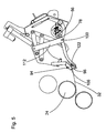
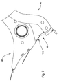
- Separator 42 has two substantially S-shaped, but almost horizontally oriented arms 92 and a counter means 94, which both serve to cut or separate a portion of the web 32 wound around a bale from a portion remaining on roll 50.
- the arms 92 carry an upwardly oriented separating edge 96 or knife and a rubber block 122, which is oriented the same way, but provided with respect to the separating edge 96 opposite of the bale chamber 16 and which forms one part of an retainer 98.
- a bearing 100 is located substantially in the transition area between the two curves of the "S" and is followed by a bearing 102 at about 2/3 of the remaining length of the second curve and a bearing 104 at the end of the arms 92.
- Counter means 94 is formed of a bent sheet metal, which in this case is flexible to some extent and has a notch 106, into which the separating edge 96 may enter and a plate 108 or surface, which is positioned such, that it can be contacted by the rubber block 122, when the separator 42 is moved against it.
- the counter means 94 is attached to the walls 48 and located close to the gap 30. Plate 108 forms another part of the retainer 98.
- the actuating mechanism 44 includes a motor 110, a link 112 and a spring 114.
- Motor 110 which may be actuated electrically, hydraulically or pneumatically is connected with one side to walls 48 or any other stationary means of the chassis 12 and with the other side to eye 88 on upper link 82.
- Link 112 is a straight rigid bar extending between and connecting bearings 90 on the upper link 82 and bearing 100 on arms 92.
- Spring 114 is formed as a gas spring, but could be of any other kind, and is connected at one end to walls 48 and at the opposite end to bearing 104 at the end of arms 92.
- a sensor 126 is located close to the travel path of these indicators to sense their movement. These indicators are offset angularly with respect to the actuators 56.
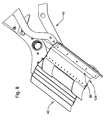
- FIG. 7 shows the feeder 40 and the separator 42 in a side view, whereas at the underside of the carrier 74 a stripper 124 is attached.
- Said stripper 124 is made of plastic and bolted, glued, riveted, clicked or otherwise fastened to the carrier 74.
- the stripper 124 extends from the lower edge of the carrier 74 forward at a length, which is sufficient to reach the separating edge 96 when the feeder 40 and the separator 42 are moved relative to each other, as this is shown in figures 7 and 8 .
- the length of the stripper 124 is chosen such, that it not only touches the tip of the separating edge 96, but strips along a slanted surface terminating in the tip.
- the stripper 124 will also strip along the opposite side of the separating edge 96, when the feeder 40 moves from its position in figure 2 to that of figure 3 .
- the Stripper 124 extends over the full length of the separating edge 96.
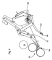
- Figure 5 shows a situation, in which motor 110 gets retracted and thereby feeder 40 is on its way back to a resting position and driver 78 approaches actuator 56.
- Dimensions, locations and arrangements of the feeder 40 and the separator 42 are chosen such, that in the situation of figure 5 , shortly before the web 32 is separated, the web 32 is pulled over rubber bloc 122 at one side and over counter means 94 on its other side, but not or hardly over the tip of separating edge 96. This helps to avoid unnecessary wear on the separating edge 96, premature tearing of the web 32 and thus achieve a quite clear cut or separation of the web 32.
- driver 78 engages actuator 56, which rotates together with roll 52.
Landscapes
- Life Sciences & Earth Sciences (AREA)
- Environmental Sciences (AREA)
- Forests & Forestry (AREA)
- Engineering & Computer Science (AREA)
- Mechanical Engineering (AREA)
- Collation Of Sheets And Webs (AREA)
- Replacement Of Web Rolls (AREA)
- Preliminary Treatment Of Fibers (AREA)
Claims (4)
- Bahnwickelvorrichtung (18) mit einer Zuführvorrichtung (40) und einem Trenner (42), der mit einer Trennkante (96) versehen ist, wobei die Zuführvorrichtung (40) und der Trenner (42) bezüglich einander beweglich sind, gekennzeichnet durch einen Abstreifer (124), der so mit der Zuführvorrichtung (40) verbunden ist, dass er die Trennkante (96) während deren Relativbewegung bezüglich der Zuführvorrichtung (40) berührt.
- Bahnwickelvorrichtung nach Anspruch 1, dadurch gekennzeichnet, dass der Abstreifer (124) als eine elastische Folie, insbesondere aus Kunststoff oder Gummi, ausgebildet ist.
- Bahnwickelvorrichtung nach Anspruch 1, dadurch gekennzeichnet, dass der Abstreifer (124) als eine Bürste ausgebildet ist.
- Bahnwickelvorrichtung nach einem oder mehreren der vorhergehenden Ansprüche, dadurch gekennzeichnet, dass der Abstreifer (124) so an der Zuführvorrichtung (40) angebracht ist, dass er die Trennkante (96) in jeder Richtung ihrer Relativbewegung berührt.
Priority Applications (3)
| Application Number | Priority Date | Filing Date | Title |
|---|---|---|---|
| EP10177082.4A EP2430902B1 (de) | 2010-09-16 | 2010-09-16 | Umhüllungsvorrichtung |
| PL10177082T PL2430902T3 (pl) | 2010-09-16 | 2010-09-16 | Urządzenie do owijania wstęgą |
| US13/234,898 US10624270B2 (en) | 2010-09-16 | 2011-09-16 | Web wrap apparatus with separator and stripper therefor |
Applications Claiming Priority (1)
| Application Number | Priority Date | Filing Date | Title |
|---|---|---|---|
| EP10177082.4A EP2430902B1 (de) | 2010-09-16 | 2010-09-16 | Umhüllungsvorrichtung |
Publications (2)
| Publication Number | Publication Date |
|---|---|
| EP2430902A1 EP2430902A1 (de) | 2012-03-21 |
| EP2430902B1 true EP2430902B1 (de) | 2013-05-08 |
Family
ID=43598035
Family Applications (1)
| Application Number | Title | Priority Date | Filing Date |
|---|---|---|---|
| EP10177082.4A Active EP2430902B1 (de) | 2010-09-16 | 2010-09-16 | Umhüllungsvorrichtung |
Country Status (3)
| Country | Link |
|---|---|
| US (1) | US10624270B2 (de) |
| EP (1) | EP2430902B1 (de) |
| PL (1) | PL2430902T3 (de) |
Cited By (1)
| Publication number | Priority date | Publication date | Assignee | Title |
|---|---|---|---|---|
| WO2016148565A1 (en) | 2015-03-18 | 2016-09-22 | Forage Innovations B.V. | Bale forming and wrapping apparatus with a guided web moving member |
Families Citing this family (5)
| Publication number | Priority date | Publication date | Assignee | Title |
|---|---|---|---|---|
| DE102014208081A1 (de) | 2014-04-29 | 2015-10-29 | Deere & Company | Ballenwickeleinrichtung und Rundballenpresse mit einer solchen |
| NL2015078B1 (en) * | 2015-07-02 | 2017-01-30 | Forage Innovations Bv | Bale forming and wrapping apparatus and method with a wrapping material severing device. |
| US11208228B2 (en) * | 2016-07-14 | 2021-12-28 | Cnh Industrial America Llc | Net wrapping system |
| DE102017209884A1 (de) * | 2017-06-12 | 2018-12-13 | Deere & Company | Umhüllungseinrichtung und Rundballenpresse |
| EP4091434A1 (de) * | 2021-05-10 | 2022-11-23 | AGCO International GmbH | Ballenpressvorrichtung |
Family Cites Families (16)
| Publication number | Priority date | Publication date | Assignee | Title |
|---|---|---|---|---|
| US3277846A (en) * | 1964-05-06 | 1966-10-11 | Samuel A Kesselman | Machine for making multiple laminated food loaf |
| DE2931968B1 (de) * | 1979-08-07 | 1981-07-16 | Heidelberger Druckmaschinen Ag, 6900 Heidelberg | Falzapparat an Rollen-Rotationsdruckmaschinen |
| DE69613526T2 (de) | 1995-10-02 | 2001-10-11 | Ford New Holland Nv | Maschine und Verfahren um Rundballen zu Umhüllen |
| US5581976A (en) * | 1995-10-02 | 1996-12-10 | New Holland North America, Inc. | Method for wrapping round bales |
| US5581973A (en) * | 1995-10-02 | 1996-12-10 | New Holland North America, Inc. | Apparatus for making round bales |
| US5581974A (en) * | 1995-10-02 | 1996-12-10 | New Holland North America, Inc. | Dual purpose cutting apparatus for round bale |
| DE19539297C1 (de) * | 1995-10-23 | 1997-04-10 | Deere & Co | Ballenpresse |
| US6272816B1 (en) * | 1999-11-12 | 2001-08-14 | Deere & Company | Large wrapping net roll pressure arm assembly serving also as a loading platform |
| US6622463B1 (en) * | 1999-11-30 | 2003-09-23 | Deere & Company | Device for folding leading end of net-type bale wrapping material to enhance its full-width conveyance into the baling chamber |
| ITRM20040176A1 (it) * | 2004-04-07 | 2004-07-07 | Ohg Ing A Ferabol I S P A | Dispositivo di legatura di una balla di foraggio o simili, mediante una rete o un foglio di altro materiale. |
| JP4924021B2 (ja) * | 2006-05-18 | 2012-04-25 | コニカミノルタビジネステクノロジーズ株式会社 | 断裁装置、後処理装置及び製本システム |
| GB2440324A (en) * | 2006-07-27 | 2008-01-30 | Cnh Belgium Nv | Clamping device for wrapping material in a round baler |
| US7430959B2 (en) | 2006-11-23 | 2008-10-07 | Elgin Routledge | Device for lifting bale wrapping rolls |
| ATE521226T1 (de) * | 2008-04-30 | 2011-09-15 | Deere & Co | Bahnwicklungsvorrichtung |
| JP5448609B2 (ja) * | 2009-06-30 | 2014-03-19 | キヤノン株式会社 | 断裁装置及び画像形成装置 |
| EP2430904B1 (de) * | 2010-09-16 | 2013-03-13 | Deere & Company | Rundballenpresse mit einer Umhüllungslvorrichtung |
-
2010
- 2010-09-16 PL PL10177082T patent/PL2430902T3/pl unknown
- 2010-09-16 EP EP10177082.4A patent/EP2430902B1/de active Active
-
2011
- 2011-09-16 US US13/234,898 patent/US10624270B2/en active Active
Cited By (1)
| Publication number | Priority date | Publication date | Assignee | Title |
|---|---|---|---|---|
| WO2016148565A1 (en) | 2015-03-18 | 2016-09-22 | Forage Innovations B.V. | Bale forming and wrapping apparatus with a guided web moving member |
Also Published As
| Publication number | Publication date |
|---|---|
| US10624270B2 (en) | 2020-04-21 |
| US20120240520A1 (en) | 2012-09-27 |
| PL2430902T3 (pl) | 2013-10-31 |
| EP2430902A1 (de) | 2012-03-21 |
Similar Documents
| Publication | Publication Date | Title |
|---|---|---|
| EP2430904B1 (de) | Rundballenpresse mit einer Umhüllungslvorrichtung | |
| EP2430902B1 (de) | Umhüllungsvorrichtung | |
| EP2229811B1 (de) | Umhüllungsvorrichtung | |
| EP2113165B1 (de) | Bahnwicklungsvorrichtung | |
| EP2430905B1 (de) | Umhüllungsvorrichtung | |
| US5916116A (en) | Apparatus for making round bales | |
| US5426923A (en) | Net supply apparatus for round balers | |
| US9149003B2 (en) | Web wrap apparatus | |
| US20040016204A1 (en) | Round baler low net indication | |
| EP2464209B1 (de) | Ballenpresse mit verbesserter abstreichwalze | |
| US5479767A (en) | Trash baffle for round baler | |
| CA2313271C (en) | Arrangement for securing loose twine ends on a cylindrical bale | |
| US4406221A (en) | Bale retainer for roll baling machine | |
| US5365836A (en) | Apparatus for wrapping round bales | |
| US5419253A (en) | Round bale wrapping method including wrapping with self-adhering tape | |
| EP2033894B1 (de) | Umwicklungsmaschine | |
| JP4589839B2 (ja) | 物品のピックアップ装置 | |
| US11116138B2 (en) | Bale forming and wrapping apparatus and method with a pivotal web pusher | |
| EP0672340A1 (de) | Vorrichtung und Verfahren zur Rundballeneinwicklung | |
| CA3171530A1 (en) | Round baler | |
| GB2610846A (en) | Baler | |
| CA1206795A (en) | Drive apparatus for roll baling machine | |
| US4414796A (en) | Method of releasing apron tension in roll baling machines | |
| JPS58155014A (ja) | 掻込装置 |
Legal Events
| Date | Code | Title | Description |
|---|---|---|---|
| PUAI | Public reference made under article 153(3) epc to a published international application that has entered the european phase |
Free format text: ORIGINAL CODE: 0009012 |
|
| AK | Designated contracting states |
Kind code of ref document: A1 Designated state(s): AL AT BE BG CH CY CZ DE DK EE ES FI FR GB GR HR HU IE IS IT LI LT LU LV MC MK MT NL NO PL PT RO SE SI SK SM TR |
|
| AX | Request for extension of the european patent |
Extension state: BA ME RS |
|
| 17P | Request for examination filed |
Effective date: 20120921 |
|
| RIC1 | Information provided on ipc code assigned before grant |
Ipc: A01F 15/07 20060101AFI20121011BHEP |
|
| GRAP | Despatch of communication of intention to grant a patent |
Free format text: ORIGINAL CODE: EPIDOSNIGR1 |
|
| GRAS | Grant fee paid |
Free format text: ORIGINAL CODE: EPIDOSNIGR3 |
|
| GRAA | (expected) grant |
Free format text: ORIGINAL CODE: 0009210 |
|
| AK | Designated contracting states |
Kind code of ref document: B1 Designated state(s): AL AT BE BG CH CY CZ DE DK EE ES FI FR GB GR HR HU IE IS IT LI LT LU LV MC MK MT NL NO PL PT RO SE SI SK SM TR |
|
| REG | Reference to a national code |
Ref country code: GB Ref legal event code: FG4D |
|
| REG | Reference to a national code |
Ref country code: AT Ref legal event code: REF Ref document number: 610608 Country of ref document: AT Kind code of ref document: T Effective date: 20130515 Ref country code: CH Ref legal event code: EP |
|
| REG | Reference to a national code |
Ref country code: IE Ref legal event code: FG4D |
|
| REG | Reference to a national code |
Ref country code: DE Ref legal event code: R096 Ref document number: 602010006888 Country of ref document: DE Effective date: 20130704 |
|
| REG | Reference to a national code |
Ref country code: NL Ref legal event code: T3 |
|
| REG | Reference to a national code |
Ref country code: AT Ref legal event code: MK05 Ref document number: 610608 Country of ref document: AT Kind code of ref document: T Effective date: 20130508 |
|
| REG | Reference to a national code |
Ref country code: LT Ref legal event code: MG4D |
|
| PG25 | Lapsed in a contracting state [announced via postgrant information from national office to epo] |
Ref country code: IS Free format text: LAPSE BECAUSE OF FAILURE TO SUBMIT A TRANSLATION OF THE DESCRIPTION OR TO PAY THE FEE WITHIN THE PRESCRIBED TIME-LIMIT Effective date: 20130908 Ref country code: NO Free format text: LAPSE BECAUSE OF FAILURE TO SUBMIT A TRANSLATION OF THE DESCRIPTION OR TO PAY THE FEE WITHIN THE PRESCRIBED TIME-LIMIT Effective date: 20130808 Ref country code: AT Free format text: LAPSE BECAUSE OF FAILURE TO SUBMIT A TRANSLATION OF THE DESCRIPTION OR TO PAY THE FEE WITHIN THE PRESCRIBED TIME-LIMIT Effective date: 20130508 Ref country code: SE Free format text: LAPSE BECAUSE OF FAILURE TO SUBMIT A TRANSLATION OF THE DESCRIPTION OR TO PAY THE FEE WITHIN THE PRESCRIBED TIME-LIMIT Effective date: 20130508 Ref country code: PT Free format text: LAPSE BECAUSE OF FAILURE TO SUBMIT A TRANSLATION OF THE DESCRIPTION OR TO PAY THE FEE WITHIN THE PRESCRIBED TIME-LIMIT Effective date: 20130909 Ref country code: FI Free format text: LAPSE BECAUSE OF FAILURE TO SUBMIT A TRANSLATION OF THE DESCRIPTION OR TO PAY THE FEE WITHIN THE PRESCRIBED TIME-LIMIT Effective date: 20130508 Ref country code: ES Free format text: LAPSE BECAUSE OF FAILURE TO SUBMIT A TRANSLATION OF THE DESCRIPTION OR TO PAY THE FEE WITHIN THE PRESCRIBED TIME-LIMIT Effective date: 20130819 Ref country code: GR Free format text: LAPSE BECAUSE OF FAILURE TO SUBMIT A TRANSLATION OF THE DESCRIPTION OR TO PAY THE FEE WITHIN THE PRESCRIBED TIME-LIMIT Effective date: 20130809 Ref country code: LT Free format text: LAPSE BECAUSE OF FAILURE TO SUBMIT A TRANSLATION OF THE DESCRIPTION OR TO PAY THE FEE WITHIN THE PRESCRIBED TIME-LIMIT Effective date: 20130508 Ref country code: SI Free format text: LAPSE BECAUSE OF FAILURE TO SUBMIT A TRANSLATION OF THE DESCRIPTION OR TO PAY THE FEE WITHIN THE PRESCRIBED TIME-LIMIT Effective date: 20130508 |
|
| REG | Reference to a national code |
Ref country code: PL Ref legal event code: T3 |
|
| PG25 | Lapsed in a contracting state [announced via postgrant information from national office to epo] |
Ref country code: CY Free format text: LAPSE BECAUSE OF FAILURE TO SUBMIT A TRANSLATION OF THE DESCRIPTION OR TO PAY THE FEE WITHIN THE PRESCRIBED TIME-LIMIT Effective date: 20130508 Ref country code: HR Free format text: LAPSE BECAUSE OF FAILURE TO SUBMIT A TRANSLATION OF THE DESCRIPTION OR TO PAY THE FEE WITHIN THE PRESCRIBED TIME-LIMIT Effective date: 20130508 Ref country code: BG Free format text: LAPSE BECAUSE OF FAILURE TO SUBMIT A TRANSLATION OF THE DESCRIPTION OR TO PAY THE FEE WITHIN THE PRESCRIBED TIME-LIMIT Effective date: 20130808 |
|
| PG25 | Lapsed in a contracting state [announced via postgrant information from national office to epo] |
Ref country code: LV Free format text: LAPSE BECAUSE OF FAILURE TO SUBMIT A TRANSLATION OF THE DESCRIPTION OR TO PAY THE FEE WITHIN THE PRESCRIBED TIME-LIMIT Effective date: 20130508 |
|
| PG25 | Lapsed in a contracting state [announced via postgrant information from national office to epo] |
Ref country code: CZ Free format text: LAPSE BECAUSE OF FAILURE TO SUBMIT A TRANSLATION OF THE DESCRIPTION OR TO PAY THE FEE WITHIN THE PRESCRIBED TIME-LIMIT Effective date: 20130508 Ref country code: DK Free format text: LAPSE BECAUSE OF FAILURE TO SUBMIT A TRANSLATION OF THE DESCRIPTION OR TO PAY THE FEE WITHIN THE PRESCRIBED TIME-LIMIT Effective date: 20130508 Ref country code: EE Free format text: LAPSE BECAUSE OF FAILURE TO SUBMIT A TRANSLATION OF THE DESCRIPTION OR TO PAY THE FEE WITHIN THE PRESCRIBED TIME-LIMIT Effective date: 20130508 Ref country code: BE Free format text: LAPSE BECAUSE OF FAILURE TO SUBMIT A TRANSLATION OF THE DESCRIPTION OR TO PAY THE FEE WITHIN THE PRESCRIBED TIME-LIMIT Effective date: 20130508 Ref country code: SK Free format text: LAPSE BECAUSE OF FAILURE TO SUBMIT A TRANSLATION OF THE DESCRIPTION OR TO PAY THE FEE WITHIN THE PRESCRIBED TIME-LIMIT Effective date: 20130508 |
|
| PG25 | Lapsed in a contracting state [announced via postgrant information from national office to epo] |
Ref country code: RO Free format text: LAPSE BECAUSE OF FAILURE TO SUBMIT A TRANSLATION OF THE DESCRIPTION OR TO PAY THE FEE WITHIN THE PRESCRIBED TIME-LIMIT Effective date: 20130508 |
|
| PLBE | No opposition filed within time limit |
Free format text: ORIGINAL CODE: 0009261 |
|
| STAA | Information on the status of an ep patent application or granted ep patent |
Free format text: STATUS: NO OPPOSITION FILED WITHIN TIME LIMIT |
|
| 26N | No opposition filed |
Effective date: 20140211 |
|
| PG25 | Lapsed in a contracting state [announced via postgrant information from national office to epo] |
Ref country code: MC Free format text: LAPSE BECAUSE OF FAILURE TO SUBMIT A TRANSLATION OF THE DESCRIPTION OR TO PAY THE FEE WITHIN THE PRESCRIBED TIME-LIMIT Effective date: 20130508 |
|
| REG | Reference to a national code |
Ref country code: DE Ref legal event code: R097 Ref document number: 602010006888 Country of ref document: DE Effective date: 20140211 |
|
| REG | Reference to a national code |
Ref country code: CH Ref legal event code: PL |
|
| GBPC | Gb: european patent ceased through non-payment of renewal fee |
Effective date: 20140916 |
|
| PG25 | Lapsed in a contracting state [announced via postgrant information from national office to epo] |
Ref country code: SM Free format text: LAPSE BECAUSE OF FAILURE TO SUBMIT A TRANSLATION OF THE DESCRIPTION OR TO PAY THE FEE WITHIN THE PRESCRIBED TIME-LIMIT Effective date: 20130508 |
|
| PG25 | Lapsed in a contracting state [announced via postgrant information from national office to epo] |
Ref country code: MT Free format text: LAPSE BECAUSE OF FAILURE TO SUBMIT A TRANSLATION OF THE DESCRIPTION OR TO PAY THE FEE WITHIN THE PRESCRIBED TIME-LIMIT Effective date: 20130508 Ref country code: TR Free format text: LAPSE BECAUSE OF FAILURE TO SUBMIT A TRANSLATION OF THE DESCRIPTION OR TO PAY THE FEE WITHIN THE PRESCRIBED TIME-LIMIT Effective date: 20130508 |
|
| PG25 | Lapsed in a contracting state [announced via postgrant information from national office to epo] |
Ref country code: GB Free format text: LAPSE BECAUSE OF NON-PAYMENT OF DUE FEES Effective date: 20140916 Ref country code: HU Free format text: LAPSE BECAUSE OF FAILURE TO SUBMIT A TRANSLATION OF THE DESCRIPTION OR TO PAY THE FEE WITHIN THE PRESCRIBED TIME-LIMIT; INVALID AB INITIO Effective date: 20100916 Ref country code: LI Free format text: LAPSE BECAUSE OF NON-PAYMENT OF DUE FEES Effective date: 20140930 Ref country code: LU Free format text: LAPSE BECAUSE OF NON-PAYMENT OF DUE FEES Effective date: 20130916 Ref country code: CH Free format text: LAPSE BECAUSE OF NON-PAYMENT OF DUE FEES Effective date: 20140930 Ref country code: MK Free format text: LAPSE BECAUSE OF FAILURE TO SUBMIT A TRANSLATION OF THE DESCRIPTION OR TO PAY THE FEE WITHIN THE PRESCRIBED TIME-LIMIT Effective date: 20130508 |
|
| REG | Reference to a national code |
Ref country code: FR Ref legal event code: PLFP Year of fee payment: 7 |
|
| REG | Reference to a national code |
Ref country code: FR Ref legal event code: PLFP Year of fee payment: 8 |
|
| REG | Reference to a national code |
Ref country code: FR Ref legal event code: PLFP Year of fee payment: 9 |
|
| PG25 | Lapsed in a contracting state [announced via postgrant information from national office to epo] |
Ref country code: AL Free format text: LAPSE BECAUSE OF FAILURE TO SUBMIT A TRANSLATION OF THE DESCRIPTION OR TO PAY THE FEE WITHIN THE PRESCRIBED TIME-LIMIT Effective date: 20130508 |
|
| PGFP | Annual fee paid to national office [announced via postgrant information from national office to epo] |
Ref country code: NL Payment date: 20230926 Year of fee payment: 14 Ref country code: IT Payment date: 20230921 Year of fee payment: 14 Ref country code: IE Payment date: 20230927 Year of fee payment: 14 |
|
| PGFP | Annual fee paid to national office [announced via postgrant information from national office to epo] |
Ref country code: PL Payment date: 20230831 Year of fee payment: 14 Ref country code: FR Payment date: 20230925 Year of fee payment: 14 Ref country code: DE Payment date: 20230821 Year of fee payment: 14 |