EP2430672B1 - Tunneldioden aus spannungskompensierten verbindungshalbleiterschichten - Google Patents
Tunneldioden aus spannungskompensierten verbindungshalbleiterschichten Download PDFInfo
- Publication number
- EP2430672B1 EP2430672B1 EP10721694.7A EP10721694A EP2430672B1 EP 2430672 B1 EP2430672 B1 EP 2430672B1 EP 10721694 A EP10721694 A EP 10721694A EP 2430672 B1 EP2430672 B1 EP 2430672B1
- Authority
- EP
- European Patent Office
- Prior art keywords
- layers
- degenerate
- layer
- solar cell
- compensated
- Prior art date
- Legal status (The legal status is an assumption and is not a legal conclusion. Google has not performed a legal analysis and makes no representation as to the accuracy of the status listed.)
- Active
Links
- 239000004065 semiconductor Substances 0.000 title claims description 95
- 150000001875 compounds Chemical class 0.000 title description 12
- 239000000463 material Substances 0.000 claims description 66
- 230000004888 barrier function Effects 0.000 claims description 27
- 229910000530 Gallium indium arsenide Inorganic materials 0.000 claims description 26
- 229910001218 Gallium arsenide Inorganic materials 0.000 claims description 19
- 229910052732 germanium Inorganic materials 0.000 claims description 11
- 229910052799 carbon Inorganic materials 0.000 claims description 8
- OKTJSMMVPCPJKN-UHFFFAOYSA-N Carbon Chemical compound [C] OKTJSMMVPCPJKN-UHFFFAOYSA-N 0.000 claims description 7
- 229910052710 silicon Inorganic materials 0.000 claims description 7
- 229910000577 Silicon-germanium Inorganic materials 0.000 claims description 6
- GNPVGFCGXDBREM-UHFFFAOYSA-N germanium atom Chemical compound [Ge] GNPVGFCGXDBREM-UHFFFAOYSA-N 0.000 claims description 6
- 229910000980 Aluminium gallium arsenide Inorganic materials 0.000 claims description 5
- 229910005542 GaSb Inorganic materials 0.000 claims description 4
- 239000010703 silicon Substances 0.000 claims description 4
- -1 GaInP Inorganic materials 0.000 claims description 3
- 229910052714 tellurium Inorganic materials 0.000 claims description 2
- PORWMNRCUJJQNO-UHFFFAOYSA-N tellurium atom Chemical compound [Te] PORWMNRCUJJQNO-UHFFFAOYSA-N 0.000 claims description 2
- JBRZTFJDHDCESZ-UHFFFAOYSA-N AsGa Chemical compound [As]#[Ga] JBRZTFJDHDCESZ-UHFFFAOYSA-N 0.000 description 19
- 239000013078 crystal Substances 0.000 description 17
- 230000007547 defect Effects 0.000 description 12
- 239000000758 substrate Substances 0.000 description 11
- 229910052738 indium Inorganic materials 0.000 description 10
- APFVFJFRJDLVQX-UHFFFAOYSA-N indium atom Chemical compound [In] APFVFJFRJDLVQX-UHFFFAOYSA-N 0.000 description 8
- 230000006978 adaptation Effects 0.000 description 6
- 238000011161 development Methods 0.000 description 6
- 230000018109 developmental process Effects 0.000 description 6
- 238000006243 chemical reaction Methods 0.000 description 5
- 229910052733 gallium Inorganic materials 0.000 description 5
- 238000004519 manufacturing process Methods 0.000 description 5
- 238000002488 metal-organic chemical vapour deposition Methods 0.000 description 5
- 238000000034 method Methods 0.000 description 5
- 238000011160 research Methods 0.000 description 5
- 238000001228 spectrum Methods 0.000 description 5
- UFHFLCQGNIYNRP-UHFFFAOYSA-N Hydrogen Chemical compound [H][H] UFHFLCQGNIYNRP-UHFFFAOYSA-N 0.000 description 4
- 229910052785 arsenic Inorganic materials 0.000 description 4
- 229910052739 hydrogen Inorganic materials 0.000 description 4
- 239000001257 hydrogen Substances 0.000 description 4
- 230000003287 optical effect Effects 0.000 description 4
- 230000005693 optoelectronics Effects 0.000 description 4
- HJUGFYREWKUQJT-UHFFFAOYSA-N tetrabromomethane Chemical compound BrC(Br)(Br)Br HJUGFYREWKUQJT-UHFFFAOYSA-N 0.000 description 4
- 239000002800 charge carrier Substances 0.000 description 3
- 238000009792 diffusion process Methods 0.000 description 3
- 238000005457 optimization Methods 0.000 description 3
- 229910052698 phosphorus Inorganic materials 0.000 description 3
- 125000006850 spacer group Chemical group 0.000 description 3
- VLCQZHSMCYCDJL-UHFFFAOYSA-N tribenuron methyl Chemical compound COC(=O)C1=CC=CC=C1S(=O)(=O)NC(=O)N(C)C1=NC(C)=NC(OC)=N1 VLCQZHSMCYCDJL-UHFFFAOYSA-N 0.000 description 3
- IJGRMHOSHXDMSA-UHFFFAOYSA-N Atomic nitrogen Chemical compound N#N IJGRMHOSHXDMSA-UHFFFAOYSA-N 0.000 description 2
- 238000004458 analytical method Methods 0.000 description 2
- 230000008901 benefit Effects 0.000 description 2
- 238000000151 deposition Methods 0.000 description 2
- 238000013461 design Methods 0.000 description 2
- 238000005516 engineering process Methods 0.000 description 2
- 238000000407 epitaxy Methods 0.000 description 2
- 238000011835 investigation Methods 0.000 description 2
- 239000000203 mixture Substances 0.000 description 2
- 230000005641 tunneling Effects 0.000 description 2
- MARUHZGHZWCEQU-UHFFFAOYSA-N 5-phenyl-2h-tetrazole Chemical compound C1=CC=CC=C1C1=NNN=N1 MARUHZGHZWCEQU-UHFFFAOYSA-N 0.000 description 1
- 108010039224 Amidophosphoribosyltransferase Proteins 0.000 description 1
- 241000819038 Chichester Species 0.000 description 1
- GYHNNYVSQQEPJS-UHFFFAOYSA-N Gallium Chemical compound [Ga] GYHNNYVSQQEPJS-UHFFFAOYSA-N 0.000 description 1
- 229910000673 Indium arsenide Inorganic materials 0.000 description 1
- GPXJNWSHGFTCBW-UHFFFAOYSA-N Indium phosphide Chemical compound [In]#P GPXJNWSHGFTCBW-UHFFFAOYSA-N 0.000 description 1
- LEVVHYCKPQWKOP-UHFFFAOYSA-N [Si].[Ge] Chemical compound [Si].[Ge] LEVVHYCKPQWKOP-UHFFFAOYSA-N 0.000 description 1
- 238000010521 absorption reaction Methods 0.000 description 1
- 230000015572 biosynthetic process Effects 0.000 description 1
- 230000000903 blocking effect Effects 0.000 description 1
- 239000012159 carrier gas Substances 0.000 description 1
- 230000008859 change Effects 0.000 description 1
- 238000005229 chemical vapour deposition Methods 0.000 description 1
- 239000002131 composite material Substances 0.000 description 1
- 230000003247 decreasing effect Effects 0.000 description 1
- 230000007850 degeneration Effects 0.000 description 1
- 230000001419 dependent effect Effects 0.000 description 1
- 230000008021 deposition Effects 0.000 description 1
- 238000010586 diagram Methods 0.000 description 1
- 238000009826 distribution Methods 0.000 description 1
- 239000002019 doping agent Substances 0.000 description 1
- 230000000694 effects Effects 0.000 description 1
- 230000005611 electricity Effects 0.000 description 1
- 239000012776 electronic material Substances 0.000 description 1
- 239000007789 gas Substances 0.000 description 1
- 229910052736 halogen Inorganic materials 0.000 description 1
- 239000012535 impurity Substances 0.000 description 1
- 238000010348 incorporation Methods 0.000 description 1
- RPQDHPTXJYYUPQ-UHFFFAOYSA-N indium arsenide Chemical compound [In]#[As] RPQDHPTXJYYUPQ-UHFFFAOYSA-N 0.000 description 1
- 230000007246 mechanism Effects 0.000 description 1
- 229910052751 metal Inorganic materials 0.000 description 1
- 239000002184 metal Substances 0.000 description 1
- 238000012986 modification Methods 0.000 description 1
- 230000004048 modification Effects 0.000 description 1
- 238000001451 molecular beam epitaxy Methods 0.000 description 1
- 150000004767 nitrides Chemical class 0.000 description 1
- 229910052757 nitrogen Inorganic materials 0.000 description 1
- 125000000962 organic group Chemical group 0.000 description 1
- 125000002524 organometallic group Chemical group 0.000 description 1
- 238000002161 passivation Methods 0.000 description 1
- 229940097322 potassium arsenite Drugs 0.000 description 1
- HEQWEGCSZXMIJQ-UHFFFAOYSA-M potassium;oxoarsinite Chemical compound [K+].[O-][As]=O HEQWEGCSZXMIJQ-UHFFFAOYSA-M 0.000 description 1
- 230000008569 process Effects 0.000 description 1
- 238000012797 qualification Methods 0.000 description 1
- 230000006798 recombination Effects 0.000 description 1
- 238000005215 recombination Methods 0.000 description 1
- 239000000523 sample Substances 0.000 description 1
- 230000001629 suppression Effects 0.000 description 1
- 230000007704 transition Effects 0.000 description 1
- 229910052725 zinc Inorganic materials 0.000 description 1
Images


Classifications
-
- H—ELECTRICITY
- H01—ELECTRIC ELEMENTS
- H01L—SEMICONDUCTOR DEVICES NOT COVERED BY CLASS H10
- H01L33/00—Semiconductor devices having potential barriers specially adapted for light emission; Processes or apparatus specially adapted for the manufacture or treatment thereof or of parts thereof; Details thereof
- H01L33/02—Semiconductor devices having potential barriers specially adapted for light emission; Processes or apparatus specially adapted for the manufacture or treatment thereof or of parts thereof; Details thereof characterised by the semiconductor bodies
- H01L33/04—Semiconductor devices having potential barriers specially adapted for light emission; Processes or apparatus specially adapted for the manufacture or treatment thereof or of parts thereof; Details thereof characterised by the semiconductor bodies with a quantum effect structure or superlattice, e.g. tunnel junction
- H01L33/06—Semiconductor devices having potential barriers specially adapted for light emission; Processes or apparatus specially adapted for the manufacture or treatment thereof or of parts thereof; Details thereof characterised by the semiconductor bodies with a quantum effect structure or superlattice, e.g. tunnel junction within the light emitting region, e.g. quantum confinement structure or tunnel barrier
-
- H—ELECTRICITY
- H01—ELECTRIC ELEMENTS
- H01L—SEMICONDUCTOR DEVICES NOT COVERED BY CLASS H10
- H01L31/00—Semiconductor devices sensitive to infrared radiation, light, electromagnetic radiation of shorter wavelength or corpuscular radiation and specially adapted either for the conversion of the energy of such radiation into electrical energy or for the control of electrical energy by such radiation; Processes or apparatus specially adapted for the manufacture or treatment thereof or of parts thereof; Details thereof
- H01L31/04—Semiconductor devices sensitive to infrared radiation, light, electromagnetic radiation of shorter wavelength or corpuscular radiation and specially adapted either for the conversion of the energy of such radiation into electrical energy or for the control of electrical energy by such radiation; Processes or apparatus specially adapted for the manufacture or treatment thereof or of parts thereof; Details thereof adapted as photovoltaic [PV] conversion devices
- H01L31/06—Semiconductor devices sensitive to infrared radiation, light, electromagnetic radiation of shorter wavelength or corpuscular radiation and specially adapted either for the conversion of the energy of such radiation into electrical energy or for the control of electrical energy by such radiation; Processes or apparatus specially adapted for the manufacture or treatment thereof or of parts thereof; Details thereof adapted as photovoltaic [PV] conversion devices characterised by potential barriers
- H01L31/068—Semiconductor devices sensitive to infrared radiation, light, electromagnetic radiation of shorter wavelength or corpuscular radiation and specially adapted either for the conversion of the energy of such radiation into electrical energy or for the control of electrical energy by such radiation; Processes or apparatus specially adapted for the manufacture or treatment thereof or of parts thereof; Details thereof adapted as photovoltaic [PV] conversion devices characterised by potential barriers the potential barriers being only of the PN homojunction type, e.g. bulk silicon PN homojunction solar cells or thin film polycrystalline silicon PN homojunction solar cells
- H01L31/0687—Multiple junction or tandem solar cells
-
- H—ELECTRICITY
- H01—ELECTRIC ELEMENTS
- H01L—SEMICONDUCTOR DEVICES NOT COVERED BY CLASS H10
- H01L33/00—Semiconductor devices having potential barriers specially adapted for light emission; Processes or apparatus specially adapted for the manufacture or treatment thereof or of parts thereof; Details thereof
- H01L33/02—Semiconductor devices having potential barriers specially adapted for light emission; Processes or apparatus specially adapted for the manufacture or treatment thereof or of parts thereof; Details thereof characterised by the semiconductor bodies
- H01L33/26—Materials of the light emitting region
- H01L33/30—Materials of the light emitting region containing only elements of Group III and Group V of the Periodic Table
-
- H—ELECTRICITY
- H01—ELECTRIC ELEMENTS
- H01L—SEMICONDUCTOR DEVICES NOT COVERED BY CLASS H10
- H01L29/00—Semiconductor devices specially adapted for rectifying, amplifying, oscillating or switching and having potential barriers; Capacitors or resistors having potential barriers, e.g. a PN-junction depletion layer or carrier concentration layer; Details of semiconductor bodies or of electrodes thereof ; Multistep manufacturing processes therefor
- H01L29/66—Types of semiconductor device ; Multistep manufacturing processes therefor
- H01L29/86—Types of semiconductor device ; Multistep manufacturing processes therefor controllable only by variation of the electric current supplied, or only the electric potential applied, to one or more of the electrodes carrying the current to be rectified, amplified, oscillated or switched
- H01L29/861—Diodes
- H01L29/88—Tunnel-effect diodes
- H01L29/885—Esaki diodes
-
- H—ELECTRICITY
- H01—ELECTRIC ELEMENTS
- H01L—SEMICONDUCTOR DEVICES NOT COVERED BY CLASS H10
- H01L33/00—Semiconductor devices having potential barriers specially adapted for light emission; Processes or apparatus specially adapted for the manufacture or treatment thereof or of parts thereof; Details thereof
- H01L33/0004—Devices characterised by their operation
- H01L33/0045—Devices characterised by their operation the devices being superluminescent diodes
-
- H—ELECTRICITY
- H01—ELECTRIC ELEMENTS
- H01S—DEVICES USING THE PROCESS OF LIGHT AMPLIFICATION BY STIMULATED EMISSION OF RADIATION [LASER] TO AMPLIFY OR GENERATE LIGHT; DEVICES USING STIMULATED EMISSION OF ELECTROMAGNETIC RADIATION IN WAVE RANGES OTHER THAN OPTICAL
- H01S5/00—Semiconductor lasers
- H01S5/10—Construction or shape of the optical resonator, e.g. extended or external cavity, coupled cavities, bent-guide, varying width, thickness or composition of the active region
- H01S5/18—Surface-emitting [SE] lasers, e.g. having both horizontal and vertical cavities
- H01S5/183—Surface-emitting [SE] lasers, e.g. having both horizontal and vertical cavities having only vertical cavities, e.g. vertical cavity surface-emitting lasers [VCSEL]
-
- H—ELECTRICITY
- H01—ELECTRIC ELEMENTS
- H01S—DEVICES USING THE PROCESS OF LIGHT AMPLIFICATION BY STIMULATED EMISSION OF RADIATION [LASER] TO AMPLIFY OR GENERATE LIGHT; DEVICES USING STIMULATED EMISSION OF ELECTROMAGNETIC RADIATION IN WAVE RANGES OTHER THAN OPTICAL
- H01S5/00—Semiconductor lasers
- H01S5/30—Structure or shape of the active region; Materials used for the active region
- H01S5/305—Structure or shape of the active region; Materials used for the active region characterised by the doping materials used in the laser structure
- H01S5/3095—Tunnel junction
-
- Y—GENERAL TAGGING OF NEW TECHNOLOGICAL DEVELOPMENTS; GENERAL TAGGING OF CROSS-SECTIONAL TECHNOLOGIES SPANNING OVER SEVERAL SECTIONS OF THE IPC; TECHNICAL SUBJECTS COVERED BY FORMER USPC CROSS-REFERENCE ART COLLECTIONS [XRACs] AND DIGESTS
- Y02—TECHNOLOGIES OR APPLICATIONS FOR MITIGATION OR ADAPTATION AGAINST CLIMATE CHANGE
- Y02E—REDUCTION OF GREENHOUSE GAS [GHG] EMISSIONS, RELATED TO ENERGY GENERATION, TRANSMISSION OR DISTRIBUTION
- Y02E10/00—Energy generation through renewable energy sources
- Y02E10/50—Photovoltaic [PV] energy
- Y02E10/544—Solar cells from Group III-V materials
-
- Y—GENERAL TAGGING OF NEW TECHNOLOGICAL DEVELOPMENTS; GENERAL TAGGING OF CROSS-SECTIONAL TECHNOLOGIES SPANNING OVER SEVERAL SECTIONS OF THE IPC; TECHNICAL SUBJECTS COVERED BY FORMER USPC CROSS-REFERENCE ART COLLECTIONS [XRACs] AND DIGESTS
- Y02—TECHNOLOGIES OR APPLICATIONS FOR MITIGATION OR ADAPTATION AGAINST CLIMATE CHANGE
- Y02E—REDUCTION OF GREENHOUSE GAS [GHG] EMISSIONS, RELATED TO ENERGY GENERATION, TRANSMISSION OR DISTRIBUTION
- Y02E10/00—Energy generation through renewable energy sources
- Y02E10/50—Photovoltaic [PV] energy
- Y02E10/547—Monocrystalline silicon PV cells
-
- Y—GENERAL TAGGING OF NEW TECHNOLOGICAL DEVELOPMENTS; GENERAL TAGGING OF CROSS-SECTIONAL TECHNOLOGIES SPANNING OVER SEVERAL SECTIONS OF THE IPC; TECHNICAL SUBJECTS COVERED BY FORMER USPC CROSS-REFERENCE ART COLLECTIONS [XRACs] AND DIGESTS
- Y02—TECHNOLOGIES OR APPLICATIONS FOR MITIGATION OR ADAPTATION AGAINST CLIMATE CHANGE
- Y02P—CLIMATE CHANGE MITIGATION TECHNOLOGIES IN THE PRODUCTION OR PROCESSING OF GOODS
- Y02P70/00—Climate change mitigation technologies in the production process for final industrial or consumer products
- Y02P70/50—Manufacturing or production processes characterised by the final manufactured product
Definitions
- the invention relates to semiconductor components, in particular solar cells made from III-V compound semiconductors, such as those used in terrestrial PV concentrator systems or for the electrical energy supply in satellites. However, it is also used in other optoelectronic components, such as lasers and light-emitting diodes, where either high tunnel current densities are required or special materials are used and where tensioning of the overall structure is not desired.
- Multi-junction solar cells consist of several pn junctions made of different semiconductor materials with a decreasing band gap.
- the semiconductor materials used are usually III-V compound semiconductors, such as gallium arsenide, and elementary semiconductors such as silicon or germanium.
- II-VI compound semiconductors such as cadmium telluride or mixed semiconductors such as silicon germanium (SiGe) can also be used.
- Multi-junction solar cells make better use of the solar spectrum than solar cells with only one pn junction and therefore achieve the highest levels of efficiency [ Dimroth, F., High-Efficiency Solar Cells from III-V Compound Semiconductors, Physica Status Solidi C, 2006, 3 (3): p. 373-9 ; Dimroth, F. and S. Kurtz, High-Efficiency Multifunction Solar Cells, MRS Bulletin, 2007, 32: p. 230-4 ]. Photoelectric conversion efficiencies of over 40% have been achieved with triple cells.
- the individual sub-cells of multi-junction solar cells must be electrically connected to one another. This connection should be transparent and have a low electrical resistance. That is why interband tunnel diodes are used in today's solar cell structures. The tunnel effect results in a low electrical resistance and a suitable choice of semiconductor materials ensures a sufficiently high optical transparency [ Bertness, KA, DJ Friedman, and JM Olson, Tunnel junction interconnects in GaAs-based multijunction solar cells, in Proceedings of the 24th Photovoltaic Specialists Conference, 1994, Waikoloa, Hawaii, USA ; Takamoto, T., et al., Two-terminal monolithic In0.5Ga0.5P / GaAs tandem solar cells with a high conversion efficiency of over 30%, Japanese Journal of Applied Physics, 1997, 36 (10): p. 6215-20 ].
- a constant lattice constant adapted to the substrate is required for all layers in order to minimize stresses and defects in the structure.
- multi-junction solar cells made of III-V compound semiconductors are typically deposited on germanium (Ge) or gallium arsenide (GaAs) substrates by means of organometallic gas phase epitaxy (MOVPE). But other methods such as molecular beam epitaxy are also used.
- MOVPE organometallic gas phase epitaxy
- the best-known multi-junction solar cell contains three pn junctions consisting of the compound semiconductors gallium indium phosphide (GaInP), gallium indium arsenide (GaInAs) and Ge [ Stan, MA, et al.
- the combination of the partial solar cells made of Ga 0.5 In 0.5 P, Ga 0.99 In 0.01 As and Ge is not yet optimally adapted to the solar spectrum. Materials with somewhat lower band gap energies are desirable. This can be achieved, for example, by adding more indium to the GaInP and the GaInAs sub-cell (In content between 5 and 17% [ King, RR, et al., 40% efficient metamorphic GaInP / GaInAs / Ge multijunction solar cells. Applied Physics Letters, 2007. 90: p. 183516-1 -3 ; Fetzer, CM, et al., High-Efflciency Metamorphic GaInP / GaInAs / Ge Solar Cells Grown by MOVPE.
- III-V multi-junction solar cells today The application of highly efficient III-V multi-junction solar cells today is on the one hand in the energy supply of satellites and probes in space [ King, RR, et al. Advanced III-V Multijunction Cell for Space. in Proceedings of the 4th World Conference on Photovoltaic Energy Conversion. 2006. Waikoloa, Hawaii, USA ; Meusel, M., et al. Development and Production of European III-V Multi-Junction Solar Cells. In Proceedings of the 22nd European Photovoltaic Solar Energy Conference and Exhibition. 2007, Milan, Italy ], and on the other hand in terrestrial PV concentrator systems [ Bett, AW and H. Lerchenmueller, The FLATCON® System from Concentrix Solar, in Concentrator Photovoltaics. 2007, Springer-Verlag GmbH. p.
- the partial solar cells of multiple solar cells are typically electrically connected to one another by tunnel diodes.
- These diodes consist mainly of semiconductor layers doped to the point of degeneration [ Esaki, L., Discovery of the tunnel diode. IEEE Transactions on Electron Devices, 1976. ED-23 (7): p. 644-7 ] and are used in addition to photovoltaics, especially in high-frequency technology and optoelectronics.
- LEDs light emitting diodes
- laser diodes eg VCSELs
- tunnel diodes are used, for example, to change the polarity of the material.
- n-material is usually lower than in p-material. This also reduces optical losses [ Manish Mehta, et al., Electrical Design Optimization of Single-Mode Tunnel-Junction-Based Long-Wavelength VCSELs. IEEE JOURNAL OF QUANTUM ELECTRONICS, 2006. 42 (7): p. 675 ; Edmond, JA, et al., Blue Light-Emitting Diode with Degenerate Junction Structure. 1994, Cree Research, Inc., Durham, NC ., U.S. 1,252.84 ].
- tunnel diodes as connecting elements is so attractive because they can meet the high requirements in terms of electrical and optical properties.
- the electrical resistance of the tunnel diode In order to transport the high photocurrents even under highly concentrated light in concentrator systems, the electrical resistance of the tunnel diode must be very low. A high electrical resistance, such as that exhibited by a normal pn diode, for example, leads to high losses. High tunnel current densities must therefore be achieved for the tunnel diode, which is achieved above all by very highly doped semiconductors with a small band gap.
- the tunnel diode should not absorb any light that is still used for photoelectric energy conversion in the sub-cells below.
- Barrier layers are attached around the pn junction of the tunnel diode in order to suppress the diffusion of the dopants from the highly doped layers [ Kojima, N., et al., Analysis of impurity diffusion from tunnel diodes and optimization for operation in tandem cells. Solar Energy Materials and Solar Cells, 1998, 50 (1-4): p. 237-42 ].
- barrier layers with a higher band gap or lower doping can also generate potential wells next to the tunnel junction, which creates a resonant interband tunnel diode [ Niu Jin, et al., 151 kA / cm2 peak current densities in Si / SiGe resonant interband tunneling diodes for highpower mixed-signal applications. Applied Physics Letters, 2003, 83 (16): p. 3308 ].
- tunnel diodes As a rule, all semiconductor layers of the tunnel diodes should be deposited in a lattice-matched manner to the surrounding semiconductor materials. Although the layers are normally thinner than the critical layer thickness, they can generate thread dislocations due to crystal tension, which extend into the sub-cells and greatly reduce the efficiency of the solar cell structure [ Guter, W., et al. Investigation and Development of III-V Triple-Junction Concentrator Solar Cells. in Proceedings of the 22nd European Photovoltaic Solar Energy Conference and Exhibition. 2007, Milan, Italy ]. In today's III-V multi-junction solar cells or other optoelectronic components, tunnel diodes are therefore deposited in a grid-matched manner to the surrounding semiconductor layers as closely as possible.
- Figure 1 illustrates the layer structure of a metamorphic triple solar cell. After a lattice-matched window layer has been applied to the Ge substrate, the lattice constant in a GaInAs buffer is increased by increasing the In content. Then tunnel diodes are deposited in a lattice-matched manner to the layers of the GaInAs center cell and to the top layer of the buffer. All layers after the buffer are largely lattice-matched to one another.
- the inverted metamorphic triple solar cell is an extension of the concept.
- the individual semiconductor layers are deposited in reverse order, for example on a GaAs substrate, which is then removed [ Geisz, IF, et al. Inverted GaInP / (In) GaAs / InGaAs Triple-Junction Solar Cells with Low-Stress Metamorphic Bottom Junctions. in Proceedings of the 33rd IEEE PVSC. 2008. San Diego ].
- the buffer structures described above can also be used between all partial cells. This means that each sub-cell can have a different lattice constant. However, all layers between the buffer structures are lattice-matched to one another.
- the US 2004/0218655 A1 relates to a light-emitting device with a substrate containing potassium arsenite, an active region and a tunnel junction structure.
- the active area includes an n-type spacer layer and a p-type spacer layer.
- the tunnel junction structure comprises a p-type tunnel junction layer besides a p-type spacer layer, an n-type tunnel junction layer and a tunnel junction between the p-type tunnel junction layer and the n-type tunnel junction layer.
- the boundary condition of the lattice adaptation is a severe restriction on the material combinations that can be used.
- highly transparent tunnel diodes one would like to use high-band gap, indirect and very thin semiconductor layers.
- high tunnel current density one would like to use highly doped, low-band gap semiconductor layers which form an optimal semiconductor heterojunction (type III). It is immediately clear that a compromise between transparency and tunnel current density has to be made for the band gap. It is all the more important to realize the other semiconductor properties, such as the indirect band gap of the p-doped layer and high doping. It becomes difficult to keep the grid matching.
- the lattice adaptation is a strict boundary condition for their structure.
- the layers of the tunnel diode are usually thin, if they are produced under strain, they can lead to crystal defects that extend into the photoactive layers of the solar cell and reduce their efficiency.
- the requirement of lattice matching severely limits the choice of possible compound semiconductor materials. Properties that are important for the tunnel diode, such as high doping and a suitable band structure, cannot be optimally adjusted.
- a multi-junction solar cell comprising at least one layer sequence of a tunnel diode sandwiched between two semiconductor layers (1, 2), degenerate layers (3, 4) and, if appropriate, barrier layers (8, 9) with a layer thickness of 10 nm to 100 nm nm, which are arranged between the degenerate layers (3, 4) and the semiconductor layers (1, 2), the degenerate layers (3, 4) having a degenerate n-conducting layer (3) and a degenerating p-conducting layer ( 4), with the proviso that the degenerate n-conductive layer (3) and the degenerate p-conductive layer (4) each have a thickness between 10 nm and 100 nm, with at least one of the two being located outside the sandwich-like arrangement
- Semiconductor layers (1, 2) iteratively connects at least one further tunnel diode and at least one further layer sequence to the further tunnel diode, wherein the degenerate n-conducting
- the present invention thus describes semiconductor components with tunnel diodes made of voltage-compensated semiconductor layers.
- Stress compensation is the method of depositing a thin semiconductor layer in a pseudomorphic manner, i.e. elastically stressed, and compensating for the resulting stress by compensating with a layer stressed in the other direction.
- a stressed layer with a lattice constant that is too large is called a “compressively stressed layer” and a stressed layer with a lattice constant that is too small is called a “tensile stressed layer”, so that a tensile stressed layer is compensated for with a compressively stressed layer.
- the critical layer thickness from which the dislocation begins must not be exceeded for the respective layer.
- tunnel diodes usually consist of thin layers
- the voltage compensation method can also be used with this component. This relaxes the requirement for lattice adaptation to the extent that only the combination of several layers should not trigger any tension.
- the individual layers may, however, be tense.
- the requirement for a constant lattice constant can be relaxed with these voltage-compensated tunnel diodes. So it is allowed to use materials with different lattice constants as long as the tension by the Layers is minimized. This significantly increases the selection of possible semiconductor materials for the production of tunnel diodes.
- the properties of the tunnel diodes can be improved by stressed layers. Interface states that are induced by local strain can, for example, increase the maximum tunnel current density many times over. Voltage compensation prevents crystal defects outside the tunnel diodes.
- the materials of the degenerate layers have mutually different lattice constants with a difference of at least 0.5.
- the difference between the lattice constants must be at least 0.5% to max. 5%, preferably at least 1% to a maximum of 2%. If these layers are deposited on one another by methods known from the prior art, the layers are braced against one another. If a layer with a larger lattice constant is grown on a layer with a smaller lattice constant, the crystal lattice of the layer with the smaller lattice constant is stretched in the growth plane. The crystal lattice of the layer with the larger lattice constant is compressed accordingly.
- a degenerate p-conducting layer made of a material with a larger lattice constant than the material of the degenerate n-conducting layer is deposited on this layer, then tensioning takes place as described above.
- the material of the p-conductive layer actually has a larger lattice constant than the material of the n-conductive layer, then, as explained above, one speaks of a compressively stressed deposited layer.
- the opposite case i.e.
- the so deposited degenerate p-conductive layer called tensile stressed layer.
- the averaged lattice constant of the degenerate layers corresponds essentially to the lattice constant of the materials of the surrounding semiconductor layers.
- essentially comprises a deviation of the averaged lattice constant of the degenerate layers from the surrounding semiconductor layers of up to 0.5%.
- the materials in question for the degenerate layers and surrounding semiconducting layers can be selected independently of one another from the group consisting of Ge, Si, SiGe, GaAs, GaSb, GaInP, AlGaAs, GaInAs, GaPN, GaInAsSb, GaInNAs, GaInAsPN, AlGaInP, AlGaInAs , AlGaAsSb, AlGaInP, GaAsSb, AlGaSb, InN, GaAsP and / or AlGaInNAs.
- the materials are selected so that they meet the requirements of claim 1, ie materials are selected that have a lattice constant that differs by at least 0.5%.
- the lattice constants are known to those skilled in the art using known diagrams showing the relationship describe between the compositions of the semiconductor compounds and the lattice constants are known. In this respect, a wide variety of materials is possible. This enables completely new types of solar cells or improved current conduction between the partial solar cells which are connected via a tunnel diode according to the invention.
- the degenerate p-conducting layer is preferably doped with carbon, and the n-conducting degenerate layer can also be doped with tellurium, silicon and / or germanium.
- tunnel diodes have a higher tunnel current density and allow the use of solar cells in highly concentrated photovoltaic systems.
- semiconductor junctions can also be made from other materials that have a better band arrangement such as InN / AlGaSb, or GaSb / InAs, or GaAs / GaSb. This also increases the maximum achievable tunnel current of the tunnel diode.
- the tensile stress of a highly carbon-doped AlGaAs layer in the tunnel diode of a metamorphic triple solar cell can be compensated for by a compressively stressed layer such as GaInAs or GaInP with a very high indium content.
- a tunnel diode with highly doped layers can therefore be produced which does not generate any defects that extend into the partial solar cells.
- tunnel diodes With voltage-compensated tunnel diodes, a largely transparent cell connection with low electrical resistance and low generation of crystal defects outside the tunnel diode is possible.
- more optimal material combinations for the tunnel diodes can also be used in other solar cell structures if the grid adaptation is replaced by the voltage compensation as a boundary condition for the production.
- the invention also includes semiconductor components that are constructed as described above, but the at least one layer sequence additionally includes at least one barrier layer with a layer thickness of 10 nm to 100 nm, the barrier layer (s) each between the degenerate layers and the surrounding semiconductor layers are arranged.
- the surrounding semiconductor layers have a higher band gap energy than the degenerate layers.
- This embodiment enables further preferred structures of the semiconductor components.
- the advantage of this embodiment is that voltage compensation can be achieved not only between the degenerate layers of the tunnel diode, but also between the barrier layers, which are also designed as thin layers, and the respectively adjoining degenerate layers.
- the semiconductor component described above is preferably constructed in such a way that that the lattice constants of the materials of the degenerate layers are stress-compensated and are essentially equal to the lattice constants of the semiconductor layers and the barrier layers.
- Another embodiment according to the invention then provides that the lattice constant of the material of a degenerate layer of the tunnel diode is greater or smaller than the lattice constant of the adjoining barrier layer.
- the averaged lattice constant of the materials of the degenerate layer and of the barrier layer are essentially the same as the surrounding semiconductor layers.
- the difference between the lattice constant of the degenerate layer and the barrier layer is at least 0.5%.
- the difference in the lattice constants is preferably at least 0.5% to a maximum of 5%, particularly preferably 1.0% to a maximum of 2%.
- the semiconductor component described above is a multiple solar cell.
- the semiconductor component can be found in solar technology, as a laser diode or as a light emitting diode.
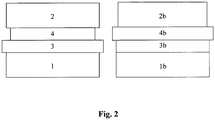
- Figure 2 shows two layer sequences of two semiconductor layers 1 and 2, between which the two layers 3 and 4 of the tunnel diode are sandwiched.
- the different widths of the respective layers indicated in the figures represent the original lattice constant of the materials used in each case for the layers.
- the material of the layer 3 has a relative to the Layer 1 has a larger lattice constant (compressively stressed), while the lattice constant of the material of layer 4 is smaller than the lattice constant of material 3 (tensile stressed).
- the material of layer 2 has a lattice constant that is approximately the same as the material used for layer 1.
- both layer 3 is tensioned on layer 1 and layer 4 is tensioned on layer 3.
- This achieves stress compensation of layers 3, 4, the mean lattice constant of which corresponds approximately to that of the semiconductor layer.
- the material used for layer 3 of the tunnel diode has a lattice constant that is approximately the same as that of the material used for layer 1 of the semiconductor composite. Tensions therefore occur at the transition from layer 3 to layer 4 and from layer 4 to layer 2.
- the material for layer 4 has a larger lattice constant than the materials used for layers 3 and 2, respectively.
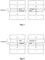
- Figure 3 shows a possible embodiment of a voltage-compensated semiconductor component in a metamorphic triple solar cell structure with GaInP top cell 2, GaInAs middle cell 1, GaInAs buffer structure 6 and Ge substrate 5.
- voltage-compensated tunnel diode layers for example GaInAs 3 and AlGaAs 4 or AlGaAsSb 7 and GaAs 8 can be used.
- the lattice constant is illustrated by the different widths of the boxes.
- the solar cell structure does not have to be metamorphic. Then a buffer layer 6 is not absolutely necessary and the respective indium contents of the partial cells are different depending on the substrate. The layer thickness of the voltage-compensated tunnel diodes must also be adapted accordingly.
- the buffer layer or the tunnel diode layers could also be used for the partial cells of the multiple solar cell, the buffer layer or the tunnel diode layers.
- AlGaInP 2, AlGaInAs 1 and GaInNAs 5 or the tunnel diodes are used in double, quadruple or quintuple cells.
- the sub-cells could for example consist of AlGaInP, GaInP, AlGaInAs, GaInAs, and Ge.
- the voltage-compensated tunnel diode can also be used in other optoelectronic components such as lasers (VCSEL with tunnel contact), light-emitting diodes or isolated tunnel diodes.
- the individual layers of the tunnel diode preferably consist of compressively tensioned AlGaInAs and tensile tensioned AlGaInAs, of compressively tensioned AlGaInP and tensile tensioned AlGaInP, of compressively tensioned AlGaInAs and tensile tensioned AlGaInP or of compressively tensioned AlGaInP or compressively tensioned AlGaInAs.
- the voltage-compensated tunnel diode can be used in tandem solar cells with two pn junctions made from GaInP and Ga (In) As, from Ga (In) As and Ge or from AlGa (In) As and Ga (In) As.
- the voltage compensated Tunnel diodes can also be used in triple solar cells with three pn junctions made from GaInP, GaInAs and Ge, from AlGaInAs, GaInAs and Ge, from AlGaInP and GaInAs and Ge.
- a triple solar cell with the voltage-compensated tunnel diode with three pn junctions made from GaInP, GaAs and GaInAs or from AlGaInP, GaAs and GaInAs is also possible.
- the voltage-compensated tunnel diode can also be used in quadruple solar cells with four pn junctions made of (Al) GaInP, (Al) GaInAs, (Al) GaInNAs, and Ge. Furthermore, the voltage-compensated tunnel diode can be used in five or six-axis solar cells with five or six pn junctions made of AlGaInP, GaInP, AlGaInAs, GaInAs, and GaInNAs and / or Ge.
- Figure 4 now shows the same schematic structure as Figure 2 the structure according to the invention of a semiconductor component.
- the structure of the degenerate layers 3, 4 has now been chosen so that one layer, in the example here layer 3, has a greater lattice constant than layer 4, which is symbolically illustrated by the greater width, so that the layer 3 is clamped compressively.
- the layer 4 is grown on tensile-tensioned in order to realize the stress compensation.
- the averaged lattice constant of these layers now essentially corresponds to the lattice constants of the semiconducting materials Layers 1, 2.
- the averaged lattice constant of the layers 4 and 8 in turn corresponds to the lattice constant of the materials of the surrounding semiconducting layers 1, 2.
- the layer 8 is tensile and the other layer 4 is tensioned compressively.
- the barrier layer 8 is compressive and the p-conductive degenerate layer 4 is tensile-tensioned.
- the lattice constants are again adapted here in comparison to the surrounding semiconductor layers 1, 2.
- FIG. 6 shows Figure 6 yet another possibility of how a semiconductor component according to the invention can be constructed.
- a Voltage compensation is now achieved here between the tunnel diode layers 3 and the barrier layers 9.
- the layer 3 is now tensile and the layer 9 is tensioned compressively, whereas in the right part the layer 9 is tensile and the layer 3 is compressively tensioned, here again in comparison to the surrounding semiconductor layers 1, 2, when the averaged material constants are determined, a Alignment is established.
- FIG. 7 now shows an application example in a metamorphic triple solar cell.
- the layers 5 and / or 6 can also consist of several semiconductor layers and possibly form a solar cell.
- the barrier layers 8, 9 of the lower tunnel diode and the barrier layer 8 of the upper tunnel diode are optional.
- Barrier layer 9 of the upper tunnel diode is used in this case for voltage compensation. Compensation means that the mean lattice constant of the stressed layers corresponds to the surrounding semiconductor layers. This also applies in the case of metamorphic structures, where the surrounding semiconductor layers 1, 2 and 7 are meant and not the layers 5 and / or 5a, which have a different or an undefined lattice constant.
Landscapes
- Engineering & Computer Science (AREA)
- Computer Hardware Design (AREA)
- Microelectronics & Electronic Packaging (AREA)
- Power Engineering (AREA)
- Manufacturing & Machinery (AREA)
- Life Sciences & Earth Sciences (AREA)
- Sustainable Energy (AREA)
- Chemical & Material Sciences (AREA)
- Crystallography & Structural Chemistry (AREA)
- Sustainable Development (AREA)
- Physics & Mathematics (AREA)
- Condensed Matter Physics & Semiconductors (AREA)
- Electromagnetism (AREA)
- General Physics & Mathematics (AREA)
- Photovoltaic Devices (AREA)
Description
- Die Erfindung bezieht sich auf Halbleiterbauteile, insbesondere Solarzellen aus III-V Verbindungshalbleitern, wie sie in terrestrischen PV Konzentratorsystemen oder zur elektrischen Energieversorgung in Satelliten eingesetzt werden. Sie findet jedoch auch Anwendung in anderen optoelektronischen Bauteilen, wie Laser und Leuchtdioden, wo entweder hohe Tunnelstromdichten nötig sind oder spezielle Materialien zum Einsatz kommen und wo eine Verspannung der Gesamtstruktur nicht erwünscht ist.
- Mehrfachsolarzellen bestehen aus mehreren p-n-Übergängen aus verschiedenen Halbleitermaterialien mit abnehmender Bandlücke. Die verwendeten Halbleitermaterialien sind in der Regel III-V Verbindungshalbleiter, wie z.B. Galliumarsenid, und Elementarhalbleiter, wie Silizium oder Germanium. Es können jedoch auch II-VI Verbindungshalbleiter, wie Cadmiumtellurid, oder Mischhalbleiter, wie Silizium-Germanium (SiGe) verwendet werden. Mehrfachsolarzellen nutzen das Sonnenspektrum besser aus als Solarzellen mit nur einem p-n-Übergang und erzielen deshalb höchste Wirkungsgrade [Dimroth, F., High-Efficiency Solar Cells from III-V Compound Semiconductors, Physica Status Solidi C, 2006, 3(3): p. 373-9; Dimroth, F. and S. Kurtz, High-Efficiency Multifunction Solar Cells, MRS Bulletin, 2007, 32: p. 230-4]. Mit Tripelzellen wurden photoelektrische Umwandlungseffizienzen von über 40 % realisiert.
- Die einzelnen Teilzellen von Mehrfachsolarzellen müssen elektrisch miteinander verbunden werden. Diese Verbindung sollte transparent sein und einen niedrigen elektrischen Widerstand aufweisen. Deshalb werden in heutigen Solarzellenstrukturen Interband-Tunneldioden eingesetzt. Durch den Tunneleffekt wird ein niedriger elektrischer Widerstand realisiert und durch geeignete Wahl der Halbleitermaterialien wird eine genügend hohe optische Transparenz gewährleistet [Bertness, K.A., D.J. Friedman, and J.M. Olson, Tunnel junction interconnects in GaAs-based multijunction solar cells, in Proceedings of the 24th Photovoltaic Specialists Conference, 1994, Waikoloa, Hawaii, USA; Takamoto, T., et al., Two-terminal monolithic In0.5Ga0.5P/GaAs tandem solar cells with a high conversion efficiency of over 30%, Japanese Journal of Applied Physics, 1997, 36 (10): p. 6215-20].
- Für Bauteile aus mehreren verschiedenen Halbleiterschichten ist in der Regel eine gleichbleibende auf das Substrat angepasste Gitterkonstante für alle Schichten erforderlich, um Spannungen und Defekte in der Struktur zu minimieren.
- Heute werden hocheffiziente Mehrfachsolarzellen aus III-V Verbindungshalbleitern typischerweise mittels metallorganischer Gasphasenepitaxie (MOVPE) auf Germanium (Ge) oder Galliumarsenid (GaAs) Substraten abgeschieden. Aber auch andere Verfahren, wie Molekülstrahlepitaxie werden verwendet. Die bekannteste Mehrfachsolarzelle enthält drei p-n-Übergängen bestehend aus den Verbindungshalbleitern Galliumindiumphosphid (GaInP), Galliumindiumarsenid (GaInAs) und Ge [Stan, M.A., et al. The Development of >28% Efficient Triple-Junction Space Solar Cells at Emcore Photovoltaics, in Technical Digest of the 3rd World Conference on Photovoltaic Energy Conversion, 2003, Osaka, Japan; Strobl, G., et al. Development and Qualification Status of European Triple Junction Solar Cells for Space Applications, in Proceedings of the 19th European Photovoltaic Solar Energy Conference, 2004, Paris, France; Baur, C., et al., Triple Junction III- V based Concentrator Solar Cells: Perspectives and Challenges. Transactions of the ASME. Journal of Solar Energy Engineering, 2006, 129(3): p. 258-65]. Eine solche Struktur kann das Sonnenspektrum aufgrund der unterschiedlichen Bandlücken der verwendeten Halbleitermaterialien deutlich effizienter ausnutzen als beispielsweise Solarzellen aus Silizium [Dimroth, F., High-Efficiency Solar Cells from III-V Compound Semiconductors, Physica Status Solidi C, 2006, 3(3): p. 373-9]. Entscheidend für die hohen Wirkungsgrade, mit denen diese Solarzellen das Sonnenlicht in elektrische Energie umwandeln, ist die hohe Kristallqualität der verwendeten Halbleiterschichten. Kristalldefekte in den Schichten bilden meist Rekombinationszentren für die photoelektrisch generierten Ladungsträger und reduzieren den Wirkungsgrad der Solarzelle. Solche Defekte können vermieden werden, wenn alle verwendeten Halbleitermaterialien dieselbe Gitterkonstante aufweisen. Dies ist bei der Tripelsolarzelle mit Teilzellen aus Ga0.5In0.5P, Ga0.99In0.01As und Ge möglich. Alle Schichten können etwa mit der Gitterkonstante von Ge auf dem Ge-Substrat abgeschieden werden.
- Die Kombination der Teilsolarzellen aus Ga0.5In0.5P, Ga0.99In0.01As und Ge ist jedoch noch nicht optimal an das Sonnenspektrum angepasst. Wünschenswert sind Materialien mit etwas geringeren Bandlückenenergien. Dies kann beispielsweise erreicht werden, indem der GaInP und der GaInAs Teilzelle mehr Indium (In Gehalt zwischen 5 und 17% [King, R.R., et al., 40% efficient metamorphic GaInP/GaInAs/Ge multijunction solar cells. Applied Physics Letters, 2007. 90: p. 183516-1 -3; Fetzer, C. M., et al., High-Efflciency Metamorphic GaInP/GaInAs/Ge Solar Cells Grown by MOVPE. Journal of Crystal Growth, 2004, 261 (2-3): p. 341-8; Dimroth, F., et al., Metamorphic GayIn1-yP/Ga1-xInxAs Tandem Solar Cells for Space and for Terrestrial Concentrator Applications at C > 1000 Suns. Progress in Photovoltaics: Research and Applications, 2001. 9(3): p. 165-1 78]) beigemischt wird. Solche Veränderungen in der Komposition der Halbleitermaterialien beeinflussen jedoch meist nicht nur deren Bandlücke, sondern auch deren Gitterkonstante [Levinshtein, M., S. Rumyantsev, and M. Shur, Ternary and Quaternary III-V Compounds. Handbook Series on Semiconductor Parameters. Vol. 2. 1999, Singapore: World Scientific Publishing Co. Pte. Ltd.]. Wird also beispielsweise die besser ans Sonnenspektrum angepasste Kombination einer Ga0.35In0.65P und Ga0.83In0.17As Teilsolarzelle auf dem Ge-Substrat abgeschieden, so haben diese Schichten eine etwa 1 % größere Gitterkonstante als das Germanium. Dies führt zur Bildung von Kristalldefekten und zu niedrigen Wirkungsgraden. Deshalb wird in sogenannten Pufferstrukturen zwischen Substrat und den gitterfehlangepassten Teilsolarzellen die Gitterkonstante kontinuierlich oder graduell verändert. Dabei ist es möglich, die Kristalldefekte sehr gut in diesen Pufferstrukturen zu lokalisieren [Schöne, J., et al., Misfit Dislocation Blocking by Dilute Nitride Intermediate Layers. Applied Physics Letters, 2008. 92(8): p. 081905; Geisz, J.F., et al., 40.8% efficient inverted triple-junction solar cell with two independently metamorphic junctions. Applied Physics Letters, 2008. 93(12): p. 123505/1 -3]. Gelingt es, dass nur sehr wenige Defekte bis in die photoaktiven Schichten der Teilzellen reichen (< 106 cm-3), können ebenfalls sehr hohe Wirkungsgrade realisiert werden [King, R.R., et al., 40% efficient metamorphic GaInP/GaInAs/Ge multijunction solar cells. Applied Physics Letters, 2007. 90: p. 183516-1 -3 8].
- Die Anwendung hocheffizienter III-V Mehrfachsolarzellen liegt heute zum einen in der Energieversorgung von Satelliten und Sonden im Weltraum [King, R.R., et al. Advanced III-V Multijunction Cell for Space. in Proceedings of the 4th World Conference on Photovoltaic Energy Conversion. 2006. Waikoloa, Hawaii, USA; Meusel, M., et al. Development and Production of European III-V Multi-Junction Solar Cells. In Proceedings of the 22nd European Photovoltaic Solar Energy Conference and Exhibition. 2007, Milan, Italy], und zum anderen in terrestrischen PV Konzentratorsystemen [Bett, A.W. and H. Lerchenmueller, The FLATCON® System from Concentrix Solar, in Concentrator Photovoltaics. 2007, Springer-Verlag GmbH. p. 301-1 9; Lerchenmueller, H., et al. from FLATCON® Pilot Systems to the first Power Plant. in Proceedings of the International Conference on Solar Concentrators for the Generation of Electricity or Hydrogen. 2007. EI Escorial, Spain].
- Die Teilsolarzellen von Mehrfachsolarzellen werden typischerweise durch Tunneldioden elektrisch miteinander verbunden. Diese Dioden bestehen vorwiegend aus bis zur Entartung dotierten Halbeiterschichten [Esaki, L., Discovery of the tunnel diode. IEEE Transactions on Electron Devices, 1976. ED-23(7): p. 644-7] und werden neben der Photovoltaik vor allem auch in der Hochfrequenztechnik und der Optoelektronik eingesetzt. In Leuchtdioden (LEDs) und Laserdioden (z.B. VCSELs) werden Tunneldioden beispielsweise eingesetzt, um die Polarität des Materials zu ändern. Durch ändern der Polarität von p auf n können aufgrund der höheren Ladungsträgermobilität Widerstandsverluste und Inhomogene Verteilung des Stromflusses reduziert werden [Manish Mehta, et al., Electrical Design Optimization of Single-Mode Tunnel-Junction-Based Long-Wavelength VCSELs. IEEE JOURNAL OF QUANTUM ELECTRONICS, 2006. 42(7): p. 675; Seong-Ran Jeon, et al., GaN-Based Light-Emitting Diodes Using Tunnel Junctions. IEEE JOURNAL OF SELECTED TOPICS IN QUANTUM ELECTRONICS, 2002. 8(4): p. 739]. Außerdem ist die freie Ladungsträgerabsorption von n-Material meist geringer als in p-Material. Somit werden auch optische Verluste reduziert [Manish Mehta, et al., Electrical Design Optimization of Single-Mode Tunnel-Junction-Based Long-Wavelength VCSELs. IEEE JOURNAL OF QUANTUM ELECTRONICS, 2006. 42(7): p. 675; Edmond, J.A., et al., Blue Light-Emitting Diode with Degenerate Junction Structure. 1994, Cree Research, Inc., Durham, N.C.,
US 1,252,84 ]. Analog zu Mehrfachsolarzellen werden in Kaskadenlasern die einzelnen Kavitäten ebenfalls mit Tunneldioden verbunden [W.J. Siskaninetz, et al., Reduced power consumption in GaAsbased bipolar cascade lasers. IEEE Electronic Letters, 2002, 38(21): p. 1259]. Bei VCSELs wird entweder durch Oxide oder mittels Tunneldioden eine optische und elektrische Apertur für höhere Leistungsdichten geschaffen [A. Bachmann, et al., Continuous-wave Operation of electrically pumped GaSbbased vertical cavity surface emitting laser at 2.3 mm. IEEE Electronic Letters, 2008. 44(3): p. 202]. - Die Verwendung von Tunneldioden als Verbindungselement ist so attraktiv, weil sie den hohen Anforderungen bezüglich elektrischer und optischer Eigenschaften genügen können. Um auch unter hochkonzentriertem Licht in Konzentratorsystemen die hohen Photoströme zu transportieren, muss der elektrische Widerstand der Tunneldiode sehr gering sein. Ein hoher elektrischer Widerstand, wie ihn beispielsweise eine normale p-n-Diode aufweist, führt zu hohen Verlusten. Für die Tunneldiode müssen deshalb hohe Tunnelstromdichten erreicht werden, was vor allem durch sehr hoch dotierte Halbleiter mit kleiner Bandlücke realisiert wird. Außerdem sollte die Tunneldiode kein Licht absorbieren, das in darunter liegenden Teilzellen noch zur photoelektrischen Energiekonversion genutzt wird. Dies wird durch dünne Schichten aus indirekten oder hochbandlückigen Halbleitermaterialien erreicht [Takamoto, T., et al., Mechanism of Zn and Si diffusion from a highly doped tunnel junction for InGaP/GaAs tandem solar cells. Journal of Applied Physics, 1999. 85(3): p. 1481-6]. Die Epitaxie von hochdotierten III-V Verbindungshalbleitern wurde von zahlreichen Forschungsgruppen weltweit untersucht
- [Scheffer, F., et al., High doping performance of lattice matched GaInP on GaAs. Journal of Crystal Growth, 1992. 124 (1-4): p. 475-82; Keiper, D., R. Westphalen, and G. Landgren, Comparison of carbon doping of InGaAs and GaAs by CBr4 using hydrogen or nitrogen as carrier gas in LP-MOVPE. Journal of Crystal Growth, 1999, 197(1-2): p. 25-30; Bettini, J., et al., Analysis of Be doping of InGaP lattice matched to GaAs. Journal of Crystal Growth, 2000, 208(1-4): p. 65-72; Dimroth, F. et al., High C-Doping of MOVPE Grown Thin AlxGa1-xAs Layers for AlGaAs/GaAs Interband Tunneling Devices. Journal of Electronic Materials, 2000, 29(1): p. 47-52; Mimila Arroyo, J., et al., Carbon acceptor doping efficiency in GaAs grown by metalorganic chemical vapor deposition. Applied Physics Letters, 2001, 79(19): p. 3095-7]. Die Tunneldioden werden meist direkt in den Halbleiterschichtstapel eingebettet und bestehen oft aus mehr als den zwei zwingend notwendigen n- bzw. p-dotierten Schichten. So werden z. B. Barriereschichten um den p-n Übergang der Tunneldiode angebracht, um die Diffusion der Dotierstoffe aus den hochdotierten Schichten zu unterdrücken [Kojima, N., et al., Analysis of impurity diffusion from tunnel diodes and optimization for operation in tandem cells. Solar Energy Materials and Solar Cells, 1998, 50(1-4): p. 237-42]. Außerdem können durch Barriereschichten mit höherer Bandlücke oder niedriger Dotierung auch Potentialtöpfe neben dem Tunnelübergang generiert werden wodurch eine resonante Interband-Tunneldiode erzeugt entsteht [Niu Jin, et al., 151 kA/cm2 peak current densities in Si/SiGe resonant interband tunneling diodes for highpower mixed-signal applications. Applied Physics Letters, 2003, 83(16): p. 3308].
- Alle Halbleiterschichten der Tunneldioden sollten in der Regel gitterangepasst zu den umliegenden Halbleitermaterialien abgeschieden werden. Obwohl die Schichten normal dünner als die kritische Schichtdicke sind, können diese durch Kristallverspannung Fadenversetzungen generieren, welche in die Teilzellen hinein reichen und den Wirkungsgrad der Solarzellenstruktur stark verringern [Guter, W., et al. Investigation and Development of III-V Triple-Junction Concentrator Solar Cells. in Proceedings of the 22nd European Photovoltaic Solar Energy Conference and Exhibition. 2007, Milan, Italy]. In heutigen III-V Mehrfachsolarzellen oder anderen optoelektronischen Bauteilen werden Tunneldioden deshalb so gut wie möglich gitterangepasst zu den umgebenden Halbleiterschichten abgeschieden.
- In den letzten Jahren hat sich neben dem gitterangepassten Wachstum verschiedener Halbleiterschichten aufeinander zunehmend das metamorphe Abscheiden von Halbleiterschichten etabliert [Dimroth, F., et al., Metamorphic GayIn1-yP/Ga1-xInxAs Tandem Solar Cells for Space and for Terrestrial Concentrator Applications at C > 1000 Suns. Progress in Photovoltaics: Research and Applications, 2001. 9(3): p. 165-1 78]. Um eine bessere Anpassung der einzelnen Teilsolarzellen einer Tripelzelle ans Sonnenspektrum zu erreichen wird zwischen der untersten Zelle aus Germanium beispielsweise ein Puffer hergestellt, der die Gitterkonstante vergrößert. In dieser Pufferschicht entsteht durch die Fehlanpassung ein dichtes Versetzungsnetzwerk. Eine wichtige Aufgabe eines solchen Puffers ist aber auch, dass diese Versetzungen nicht in die photoaktiven Teile des Zellstapels vordringen, sondern im Puffer lokalisiert bleiben.
Figur 1 veranschaulicht den Schichtaufbau einer metamorphen Tripelsolarzelle. Nachdem auf das Ge-Substrat eine gitterangepasste Fensterschicht aufgebracht wurde, wird die Gitterkonstante in einem GaInAs Puffer durch einen ansteigenden In-Gehalt vergrößert. Danach werden Tunneldioden gitterangepasst zu den Schichten der GaInAs Mittelzelle und zur obersten Schicht des Puffers abgeschieden. Alle Schichten nach dem Puffer sind weitgehend gitterangepasst zueinander. - Eine Erweiterung des Konzepts ist die invertierte metamorphe Tripelsolarzelle. Dabei werden die einzelnen Halbleiterschichten zum einen in umgekehrter Reihenfolge beispielsweise auf einem GaAs Substrat abgeschieden, welches danach entfernt wird [Geisz, I. F., et al. Inverted GaInP/(In)GaAs/InGaAs Triple-Junction Solar Cells with Low-Stress Metamorphic Bottom Junctions. in Proceedings of the 33rd IEEE PVSC. 2008. San Diego]. Um noch freier in der Wahl der einzelnen Teilsolarzellen zu sein, können auch zwischen allen Teilzellen oben beschriebene Pufferstrukturen eingesetzt werden. Dadurch kann jede Teilzelle eine andere Gitterkonstante besitzen. Alle Schichten zwischen den Pufferstrukturen sind jedoch gitterangepasst zueinander. Das gilt auch für die Tunneldioden, die sich über oder unter der Teilzelle befinden [Geisz, I. F., et al. Inverted GaInP/(In)GaAs/InGaAs Triple-Junction Solar Cells with Low-Stress Metamorphic Bottom Junctions. in Proceedings of the 33rd IEEE PVSC. 2008. San Diego].
- Die
US 2004/0218655 A1 betrifft eine lichtemittierende Vorrichtung mit einem Substrat enthaltend Kaliumarsenit, einem aktiven Bereich und einer Tunnelübergangsstruktur. Der aktive Bereich umfasst eine Abstandsschicht vom n-Typ und eine Abstandsschicht vom p-Typ. Die Tunnelübergangsstruktur umfasst eine p-Typ-Tunnelübergangsschicht neben einer p-Typ-Abstandsschicht, eine n-Typ-Tunnelübergangsschicht und einen Tunnelübergang zwischen der p-Typ-Tunnelübergangsschicht und der n-Typ-Tunnelübergangsschicht. - Aus DIMROTH F ET Al: "METAMORPHIC GayIn1-yP/Ga1-xInxAs TANDEM SOLAR CELLS FOR SPACE AND FOR TERRESTRIAL CONCENTRATOR APPLICATIONS AT C>1000 SUNS", PROGRESS IN PHOTOVOLTAICS: RESEARCH AND APPLICATIONS, JOHN WILEY AND SONS; CHICHESTER, GB, Bd. 9, Nr. 3, 1. Mai 2001 (2001-05-01), Seiten 165-178, XP008060557ISSN: 1062-7995 ist eine Solarzelle mit einer Tunneldiode aus einer entarteten p-leitenden Schicht und einer entarteten n-leitenden Schicht offenbart und hierbei wird insbesondere der Austausch von GaAs gegen Ga1-xInxAs als Substratmaterial erwähnt. Nachteile Stand der Technik
- Die Randbedingung der Gitteranpassung ist eine starke Einschränkung an einsetzbaren Materialkombinationen. Um hochtransparente Tunneldioden herzustellen, würde man gerne hochbandlückige, indirekte und sehr dünne Halbleiterschichten dafür verwenden. Um eine hohe Tunnelstromdichte zu realisieren, würde man gerne hochdotierte, niedrigbandlückige Halbleiterschichten verwenden, die einen optimalen Halbleiterheteroübergang ausbilden (Typ III). Es ist sofort klar, dass für die Bandlücke ein Kompromiss aus Transparenz und Tunnelstromdichte eingegangen werden muss. Umso wichtiger ist es, die anderen Halbleitereigenschaften, wie indirekte Bandlücke der p-dotierten Schicht und hohe Dotierung, zu realisieren. Dabei wird es schwierig, die Gitteranpassung einzuhalten. Wird die Gitterkonstante der Halbleiterschichten in der Tunneldiode zu klein oder zu groß gewählt, baut sich selbst bei dünnen nur leicht verspannten Schichten genug Spannung auf, um Kristalldefekte zu generieren, die auch in umliegende Halbleiterschichten hinein reichen. Dabei muss die Dicke der Tunneldiodenschichten nicht einmal die kritische Schichtdicke überschreiten.
- In gitterangepassten Tripelsolarzellen auf Ge ist man deshalb im Wesentlichen auf (AlxGa1-x)0.99In0.01As und (AlxGa1-x)0.5In0.5P beschränkt. Da in metamorphen Tripelzellen die Teilzellen aus GaInAs mit bis zu 40% In und aus GaInP mit bis zu 65% In bestehen ist man in diesem je nach Material auch auf AlGaInAs mit Indium-Gehalten bis zu 40% und AlGaInP mit Indium-Gehalten bis zu 65% beschränkt. Insbesondere der Einsatz von indirekten Halbleitermaterialien mit niedriger Bandlücke und von Halbleitergrenzflächen mit Typ III Heteroübergang ist so nur eingeschränkt möglich. Ein höherer Kohlenstoffgehalt in AlGaInAs reduziert zusätzlich dessen Gitterkonstante, was z.B. durch einen höheren Indiumgehalt ausgeglichen werden kann.
- Durch den hohen Indium Gehalt in AlGaInAs bei metamorphen Strukturen, sind diese Schichten schwieriger p-dotierbar. Kohlenstoffhalogene, wie Kohlenstofftetrabromid (CBr4), reduzieren den Indium Einbau, so dass keine Gitteranpassung der Schicht möglich ist [Guter, W., et al. Investigation and Development of III-V Triple-Junction Concentrator Solar Cells. in Proceedings of the 22nd European Photovoltaic Solar Energy Conference and Exhibition. 2007, Milan, Italy]. Bei intrinsischer Dotierung mit Kohlenstoff aus den organischen Gruppen der Metallorganika ist ein Großteil des eingebauten Kohlenstoffs nicht elektrisch aktiv, weil er mit Wasserstoff passiviert ist [Oda, Y., et al., Suppression of hydrogen passivation in carbon-doped GaAsSb grown by MOCVD. Journal of Crystal Growth, 2004. 261(2-3): p. 393-397]. In diesem Fall muss also ein Kompromiss zwischen Gitteranpassung und Dotierung eingegangen werden. Entweder wird eine gitterfehlangepasste Tunneldiodenschicht in Kauf genommen, die den Wirkungsgrad der Solarzelle stark reduziert, oder es wird eine niedrige p-Dotierung in Kauf genommen. Dann ist die Zellstruktur aufgrund der Tunneldiode jedoch nicht für hoch-konzentrierende Photovoltaik Systeme geeignet.
- Nach dem heutigen Stand der Technik ist es nicht möglich Tunneldioden mit sehr hohen Tunnelströmen in metamorphen Strukturen herzustellen. In der Vergangenheit wurden oft fehlangepasste Schichten hingenommen. Diese generieren Kristalldefekte, welche den Wirkungsgrad der Solarzellenstruktur verringern.
- Da die Halbleiterschichten der Tunneldioden gitterangepasst an die umliegenden Halbleiterschichten gezüchtet werden müssen, stellt die Gitteranpassung eine strenge Randbedingung an deren Aufbau dar. Obwohl die Schichten der Tunneldiode in der Regel dünn sind, können diese, wenn sie verspannt hergestellt werden, zu Kristalldefekten führen, die bis in die photoaktiven Schichten der Solarzelle reichen und deren Wirkungsgrad reduzieren. Die Forderung von Gitteranpassung schränkt jedoch die Wahl an möglichen Verbindungshalbleiter-Materialien stark ein. Für die Tunneldiode wichtige Eigenschaften, wie hohe Dotierung und passende Bandstruktur können nicht optimal eingestellt werden.
- Es ist daher die Aufgabe der vorliegenden Erfindung, die Randbedingung, dass alle Schichten gitterangepasst zueinander hergestellt werden sollen, zu lockern und somit eine größere Materialauswahl speziell aufeinander abgeschiedener Halbleiterschichten zu ermöglichen.
- Diese Aufgabe wird bezüglich der Mehrfachsolarzelle mit den Merkmalen des Patentanspruchs 1 gelöst. Die abhängigen Patentansprüche stellen dabei vorteilhafte Weiterbildungen dar.
- Erfindungsgemäß wird somit eine Mehrfachsolarzelle bereitgestellt, umfassend mindestens eine Schichtfolge einer Tunneldiode, die sandwichartig zwischen zwei Halbleiterschichten (1, 2) angeordnet ist, entartete Schichten (3, 4) und gegebenenfalls Barriereschichten (8, 9) mit einer Schichtdicke von 10 nm bis 100 nm aufweist, die zwischen den entarteten Schichten (3, 4) und den Halbleiterschichten (1, 2) angeordnet sind, wobei die entarteten Schichten (3, 4) eine entartete n-leitende Schicht (3) sowie eine entartete p-leitende Schicht (4) sind, mit der Maßgabe, dass die entartete n-leitende Schicht (3) und die entartete p-leitende Schicht (4) jeweils eine Dicke zwischen 10 nm und 100 nm aufweisen, wobei sich außerhalb der sandwichartigen Anordnung an zumindest einer der zwei Halbleiterschichten (1, 2) iterativ mindestens eine weitere Tunneldiode sowie an die weitere Tunneldiode mindestens eine weitere Schichtfolge anschließt,
wobei die entartete n-leitende Schicht (3) mit der entarteten p-leitenden Schicht (4) spannungskompensiert ist oder wobei die entartete n-leitende Schicht (3) oder die entartete p-leitende Schicht (4) mit der angrenzenden Barriereschicht (8, 9) spannungskompensiert ist und die Gitterkonstanten der Materialien der untereinander spannungskompensierten Schichten einen Unterschied von mindestens 0,5 % aufweisen. - Die vorliegende Erfindung beschreibt somit Halbleiterbauteile mit Tunneldioden aus spannungskompensierten Halbleiterschichten. Unter Spannungskompensation versteht man die Methode, eine dünne Halbleiterschicht pseudomorph, also elastisch verspannt, abzuscheiden und die entstehende Verspannung durch Kompensation mit einer in die andere Richtung verspannten Schicht zu kompensieren. Erfindungsgemäß wird eine Verspannung durch eine verspannte Schicht mit zu großer Gitterkonstante als "kompressiv verspannte Schicht" und eine verspannten Schicht mit einer zu kleinen Gitterkonstanten als "tensil verspannte Schicht" bezeichnet, so dass eine tensil verspannte Schicht mit einer kompressiv verspannten Schicht kompensiert wird. Dazu darf bei der jeweiligen Schicht die kritische Schichtdicke, ab dieser Versetzungsbildung einsetzt, nicht überschritten werden. Solche Verfahren werden heute etwa bei der Herstellung von Quantentöpfen eingesetzt. Da Tunneldioden in der Regel aus dünnen Schichten bestehen, kann die Methode der Spannungskompensation auch bei diesem Bauelement angewendet werden. Dies lockert die Forderung nach Gitteranpassung in sofern, als dass nur die Kombination mehrerer Schichten keine Verspannung auslösen soll. Die einzelnen Schichten dürfen allerdings verspannt sein. Die Forderung nach einer gleichbleibenden Gitterkonstanten kann mit diesen spannungskompensierten Tunneldioden gelockert werden. Es dürfen also Materialien mit unterschiedlicher Gitterkonstante verwendet werden, solange die Verspannung durch die Schichten minimiert wird. Dadurch wird die Auswahl an möglichen Halbleitermaterialien zur Herstellung von Tunneldioden deutlich erhöht. Außerdem können die Eigenschaften der Tunneldioden durch verspannte Schichten verbessert werden. Grenzflächenzustände, welche durch lokale Verspannung induziert werden, können beispielsweise die maximale Tunnelstromdichte um ein vielfaches erhöhen. Durch Spannungskompensation werden Kristalldefekte außerhalb der Tunneldioden vermieden.
- Erfindungsgemäß ist somit in einer ersten Ausführungsform vorgesehen, dass die Materialien der entarteten Schichten zueinander unterschiedliche Gitterkonstanten mit einem Unterschied von mindestens 0,5 aufweisen. Die Differenz der Gitterkonstanten muss dabei mindestens 0,5 % bis max. 5 %, bevorzugt mindestens 1 % bis maximal 2 %, betragen. Werden diese Schichten durch aus dem Stand der Technik bekannten Methoden aufeinander abgeschieden, erfolgt ein Verspannen der Schichten gegeneinander. Wird somit eine Schicht mit größerer Gitterkonstante auf einer Schicht mit kleinerer Gitterkonstante aufgewachsen, so wird das Kristallgitter der Schicht mit der kleineren Gitterkonstante in Wachstumsebene gedehnt. Entsprechend wird das Kristallgitter der Schicht mit der größeren Gitterkonstante komprimiert. Wird beispielsweise eine entartete p-leitende Schicht aus einem Material mit einer größeren Gitterkonstante als das Material der entarteten n-leitenden Schicht auf diese Schicht abgeschieden, so erfolgt ein Verspannen wie vorstehend beschrieben. Für das voranstehende Beispiel, in dem das Material der p-leitenden Schicht eine eigentlich größere Gitterkonstante als das Material der n-leitenden Schicht aufweist, spricht man dann wie vorstehend erläutert von einer kompressiv verspannt abgeschiedenen Schicht. Für den umgekehrten Fall, also beispielhaft für den Fall, dass die Gitterkonstante des Materials einer der entarteten p-leitenden Schicht, die auf einer n-leitenden Schicht abgeschieden werden soll, eine kleinere Gitterkonstante als das Material der n-leitenden Schicht aufweist, wird die so abgeschiedene entartete p-leitende Schicht als tensil verspannte Schicht bezeichnet.
- Erfindungsgemäß ist es bei dem Halbleiterbauelement in einer ersten Ausführungsform bevorzugt, wenn die gemittelte Gitterkonstante der entarteten Schichten im Wesentlichen der Gitterkonstante der Materialien der umgebenden Halbleiterschichten entspricht. Mit im Wesentlichen ist erfindungsgemäß eine Abweichung der gemittelten Gitterkonstante der entarteten Schichten zu den umgebenden Halbleiterschichten von bis zu 0,5 % umfasst.
- Selbstverständlich ist auch eine nicht zur Erfindung gehörende Ausführungsform möglich, bei der eine Verspannung zwischen einer entarteten Schicht und einer umgebenden Halbleiterschicht realisiert ist.
- Die für die entarteten Schichten und umgebenden halbleitenden Schichten in Frage kommenden Materialien können unabhängig voneinander ausgewählt sein aus der Gruppe bestehend aus Ge, Si, SiGe, GaAs, GaSb, GaInP, AlGaAs, GaInAs, GaPN, GaInAsSb, GaInNAs, GaInAsPN, AlGaInP, AlGaInAs, AlGaAsSb, AlGaInP, GaAsSb, AlGaSb, InN, GaAsP und/oder AlGaInNAs. Die Materialien werden dabei so gewählt, dass sie den Anforderungen des Anspruchs 1 genügen, d.h. es werden Materialien gewählt, die eine mindestens um 0,5 % verschiedene Gitterkonstante aufweisen. Die Gitterkonstanten sind dem Fachmann anhand bekannter Diagramme, die den Zusammenhang zwischen den Zusammensetzungen der Halbleiterverbindungen und den Gitterkonstanten beschreiben, bekannt. Insofern ist eine breite Varianz an Materialien möglich. Dies ermöglicht völlig neuartige Solarzellen bzw. eine verbesserte Stromleitung zwischen den Teilsolarzellen, die über eine erfindungsgemäße Tunneldiode verbunden sind.
- Vorzugsweise ist die entartete p-leitende Schicht mit Kohlenstoff dotiert, ebenso kann die n-leitende entartete Schicht mit Tellur, Silicium und/oder Germanium dotiert sein.
- Mit den erfindungsgemäßen Halbleiterbauteilen, die die erfindungsgemäß definierten Tunneldioden beinhalten, gehen wesentliche Vorteile einher.
- Solche Tunneldioden besitzen eine höhere Tunnelstromdichte und erlauben den Einsatz der Solarzelle auch in hochkonzentrierenden Photovoltaiksystemen. Durch spannungskompensierte Schichten in der Tunneldiode lassen sich auch Halbleiterübergänge aus weiteren Materialien realisieren, die eine bessere Band-Anordnung haben wie zum Beispiel InN/AlGaSb, oder GaSb/InAs, oder GaAs/GaSb. Auch dies erhöht den maximal erreichbaren Tunnelstrom der Tunneldiode.
- Konkret kann die tensile Verspannung einer hoch Kohlenstoffdotierten AlGaAs Schicht in der Tunneldiode einer metamorphen Tripelsolarzelle durch eine kompressiv verspannte Schicht, wie GaInAs oder GaInP mit sehr hohen Indiumgehalt, kompensiert werden. Es kann also eine Tunneldiode mit hochdotierten Schichten hergestellt werden, die keine Defekte generiert, welche in die Teilsolarzellen reichen.
- Mit spannungskompensierten Tunneldioden ist eine weitgehend transparente Teilzellen-Verbindung mit niedrigem elektrischen Widerstand und geringen Generation von Kristalldefekten außerhalb der Tunneldiode möglich. Außerdem können auch in anderen Solarzellenstrukturen optimalere Materialkombinationen für die Tunneldioden eingesetzt werden, wenn die Gitteranpassung durch die Spannungskompensation als Randbedingung für die Herstellung ersetzt wird.
- Die Erfindung umfasst weiterhin auch Halbleiterbauteile, die wie vorstehend beschrieben aufgebaut sind, wobei jedoch die mindestens eine Schichtenfolge zusätzlich mindestens eine Barriereschicht mit einer Schichtdicke von 10 nm bis 100 nm umfasst, wobei die Barriereschicht(en) jeweils zwischen den entarteten Schichten und den umgebenden Halbleiterschichten angeordnet sind.
- Es ist dabei vorteilhaft, wenn die umgebenden Halbleiterschichten eine höhere Bandlückenenergie als die entarteten Schichten aufweisen.
- Durch diese Ausführungsform sind weitere bevorzugte Aufbauten der Halbleiterbauteile möglich.
- Der Vorteil dieser Ausführungsform besteht nun darin, dass eine Spannungskompensation nicht nur zwischen den entarteten Schichten der Tunneldiode, sondern auch noch zwischen den Barriereschichten, die ebenfalls als dünne Schichten ausgebildet sind, und den jeweils angrenzenden entarteten Schichten erreicht werden kann.
- Bevorzugt ist das vorstehend beschriebene Halbleiterbauteil in einer ersten Variante dabei so aufgebaut, dass die Gitterkonstanten der Materialien der entarteten Schichten spannungskompensiert und im Wesentlichen gleich der Gitterkonstanten der Halbleiterschichten und der Barriereschichten sind.
- Eine weitere Ausführungsform gemäß der Erfindung sieht dann vor, dass die Gitterkonstante des Materials einer entarteten Schicht der Tunneldiode größer oder kleiner ist als die Gitterkonstante der angrenzenden Barriereschicht. Dadurch sind nun Aufbauten möglich, bei der die gemittelte Gitterkonstante der Materialien der entarteten Schicht und der Barriereschicht im Wesentlichen gleich der umgebenden Halbleiterschichten sind. Für die vorstehend beschriebene Ausführungsform mit einer Schichtenfolge, bei der zusätzliche Barriereschichten vorgesehen sind, beträgt die Differenz zwischen der Gitterkonstante der entarteten Schicht und der Barriereschicht mindestens 0,5 %. Bevorzugt beträgt die Differenz der Gitterkonstanten mindestens 0,5 % bis maximal 5 %, besonders bevorzugt 1,0 % bis maximal 2 %.
- Erfindungsgemäß ist das zuvor beschriebenes Halbleiterbauteil eine Mehrfachsolarzelle.
- Weitere Verwendungsmöglichkeiten des Halbleiterbauteils finden sich in der Solartechnik, als Laserdiode oder als Leuchtdiode.
- Das erfindungsgemäße Konzept wird anhand der nachfolgenden beispielhaften Ausführungen sowie den Figuren näher erläutert, ohne die Erfindung auf die dargestellten Ausführungsformen zu beschränken.
- Dabei zeigen
- Figur 1
- den schematischen Aufbau einer metamorphen Tripelsolarzelle gemäß dem Stand der Technik.
- Figur 2
- zwei Ausführungsformen eines Halbleiterbauteils.
- Figur 3
- eine metamorphe Tripelsolarzelle, die ein Halbleiterbauteil mit zwei erfindungsgemäßen Tunneldioden umfasst.
- Figur 4
- eine weitere Ausführungsform eines Halbleiterbauteils mit Barriereschichten.
- Figur 5
- eine Ausführungsform der Erfindung mit Barriereschichten und Spannungskompensation mit der Barriereschicht.
- Figur 6
- eine Abwandlung der Ausführungsform nach
Figur 5 . - Figur 7
- den Aufbau einer metamorphen Tripelsolarzelle.
-
Figur 2 zeigt zwei Schichtabfolgen aus zwei Halbleiterschichten 1 und 2, zwischen die die beiden Schichten 3 und 4 der Tunneldiode sandwichartig eingeschlossen sind. Die unterschiedliche in den Figuren angedeutete Breite der jeweiligen Schichten repräsentiert dabei die originäre Gitterkonstante der jeweils für die Schichten verwendeten Materialien. In der linken Ausführungsform des Halbleiterbauteils derFigur 2 weist erfindungsgemäß das Material der Schicht 3 eine bezüglich der Schicht 1 größere Gitterkonstante auf (kompressiv verspannt), während die Gitterkonstante des Materials der Schicht 4 kleiner als die Gitterkonstante des Materials 3 ist (tensil verspannt). Das Material der Schicht 2 weist eine ungefähr gleich große Gitterkonstante auf, wie das Material, das für Schicht 1 verwendet wird. Im Fall des Halbleiterbauteils der linken Ausführungsform derFigur 2 ist somit sowohl die Schicht 3 verspannt auf der Schicht 1 als auch die Schicht 4 verspannt auf der Schicht 3. Dadurch wird eine Spannungskompensation der Schichten 3, 4 erreicht, deren gemittelte Gitterkonstante in etwa der der Halbleiterschicht entspricht. - In der nicht zur Erfindung gehörenden Ausführungsform der
Figur 2 weist das für die Schicht 3 der Tunneldiode verwendete Material eine ungefähr gleich große Gitterkonstante auf wie das für die Schicht 1 des Halbleiterverbundes verwendete Material. Verspannungen treten hierbei somit beim Übergang der Schicht 3 auf Schicht 4 sowie von Schicht 4 auf Schicht 2 auf. Dabei weist das Material für Schicht 4 eine größere Gitterkonstante auf, als die für die Schichten 3 bzw. 2 verwendeten Materialien. -
Figur 3 zeigt ein mögliches Ausführungsbeispiel eines spannungskompensierten Halbleiterbauteils in einer metamorphen Tripel-Solarzellenstruktur mit GaInP Oberzelle 2, GaInAs Mittelzelle 1, GaInAs Pufferstruktur 6 und Ge-Substrat 5. Für die spannungskompensierten Tunneldiodenschichten können beispielsweise
GaInAs 3 und AlGaAs 4 bzw. AlGaAsSb 7 und GaAs 8 verwendet werden. Dazu kommen eine hoch dotierte Cap-Schicht 9, eine Antireflexionsschicht 10, ein Vorderseitenkontakt 11 und ein Rückseitenkontakt 12. Auch hier wird die Gitterkonstante durch eine unterschiedliche Breite der Kästchen veranschaulicht. - Alternativ muss die Solarzellenstruktur nicht metamorph sein. Dann wird eine Pufferschicht 6 nicht unbedingt benötigt und die jeweiligen Indium-Gehalte der Teilzellen sind je nach Substrat anders. Entsprechend muss auch die Schichtdicke der spannungskompensierten Tunneldioden angepasst werden.
- Des Weiteren könnten auch andere Materialien für die Teilzellen der Mehrfachsolarzelle, die Pufferschicht oder die Tunneldiodenschichten verwendet werden. Zum Beispiel AlGaInP 2, AlGaInAs 1 und GaInNAs 5 oder die Tunneldioden werden in Zweifach- Vierfach oder Fünffach-Zellen eingesetzt. Bei der Fünffach-Zelle könnten die Teilzellen beispielsweise aus AlGaInP, GaInP, AlGaInAs, GaInAs, und Ge bestehen.
- Außerdem kann die spannungskompensierte Tunneldiode auch in anderen optoelektronischen Bauteilen, wie Laser (VCSEL mit Tunnelkontakt), Leuchtdioden oder isolierten Tunneldioden eingesetzt werden.
- Die einzelnen Schichten der Tunneldiode bestehen bevorzugt aus kompressiv verspanntem AlGaInAs und tensil verspanntem AlGaInAs, aus kompressiv verspanntem AlGaInP und tensil verspanntem AlGaInP, aus kompressiv verspanntem AlGaInAs und tensil verspanntem AlGaInP oder aus kompressiv verspanntem AlGaInP und tensil verspanntem AlGaInAs.
- Die spannungskompensierte Tunneldiode kann in Tandemsolarzellen mit zwei p-n-Übergängen aus GaInP und Ga(In)As, aus Ga(In)As und Ge oder aus AlGa(In)As und Ga(In)As verwendet werden. Die spannungskompensierte Tunneldiode kann ebenso in Tripelsolarzellen mit drei p-n-Übergängen aus GaInP, GaInAs und Ge, aus AlGaInAs, GaInAs und Ge, aus AlGaInP und GaInAs und Ge, verwendet werden. Ebenso ist eine Tripelsolarzelle mit der spannungskompensierten Tunneldiode mit drei p-n-Übergängen aus GaInP, GaAs und GaInAs oder aus AlGaInP, GaAs und GaInAs möglich. Die spannungskompensierte Tunneldiode kann auch in Vierfachsolarzellen mit vier p-n-Übergängen aus (Al)GaInP, (Al)GaInAs, (Al)GaInNAs, und Ge verwendet werden. Weiterhin ist die spannungskompensierte Tunneldiode in Fünf- oder Sechsfachsolarzellen mit fünf oder sechs p-n-Übergängen aus AlGaInP, GaInP, AlGaInAs, GaInAs, und GaInNAs und/oder Ge verwendbar.
-
Figur 4 zeigt nun analog schematisch im Aufbau wieFigur 2 den erfindungsgemäßen Aufbau eines Halbleiterbauteils. - Die in
Figur 4 , linker Teil dargestellte Ausführungsform zeigt nun ein Beispiel, bei dem zusätzlich Barriereschichten 8, 9 zwischen den entarteten Schichten 3, 4 und den Halbleiterschichten 1, 2 angeordnet sind. - Bei der Ausführungsform nach
Figur 4 , linker Teil ist nun der Aufbau der entarteten Schichten 3, 4 so gewählt worden, dass eine Schicht, im Beispielsfall hier die Schicht 3, eine größere Gitterkonstante aufweist als die Schicht 4, was symbolisch durch die größere Breite veranschaulicht ist, so dass die Schicht 3 kompressiv verspannt ist. Die Schicht 4 wird tensil-verspannt aufgewachsen um die Spannungskompensation zu realisieren. Die gemittelte Gitterkonstante dieser Schichten entspricht nun im Wesentlichen den Gitterkonstanten der Materialien der halbleitenden Schichten 1, 2. - Genauso ist natürlich eine Ausführungsform möglich, bei der die p-leitende Schicht 4 kompressiv, d.h. eine größere Gitterkonstante aufweist und die n-leitende entartete Schicht 3 eine kleinere Gitterkonstante und somit tensil-verspannt ist, so dass aber im Ergebnis wiederum die gemittelte Gitterkonstante der Materialien der Schichten 3 und 4 im Wesentlichen den Gitterkonstanten der halbleitenden Schichten 1, 2 entspricht. In
Figur 5 ist nun eine weitere Ausführungsform dargestellt, bei der eine Spannungskompensation zwischen den Tunneldiodenschichten und den Barriereschichten realisiert ist. Im Beispielsfall nachFigur 5 , linker Teil ist dabei die entartete p-leitende Schicht 4 kompressiv-verspannt, d.h. sie weist eine größere Gitterkonstante als die angrenzende Schicht 3 auf. Entscheidend ist nun, dass die gemittelte Gitterkonstante der Schichten 4 und 8 nun wiederum der Gitterkonstante der Materialien der umgebenden halbleitenden Schichten 1, 2 entspricht. Im Ergebnis ist somit die Schicht 8 tensil und die andere Schicht 4 kompressiv verspannt. - Im rechten Teil ist nun ein umgekehrter Aufbau gewählt, d.h. hier ist die Barriereschicht 8 kompressiv und die p-leitende entartete Schicht 4 tensil-verspannt. Im Ergebnis erfolgt aber auch hier wieder im Vergleich zu den umgebenden Halbleiterschichten 1, 2 eine Anpassung der Gitterkonstanten.
- Letztlich zeigt
Figur 6 noch eine weitere Möglichkeit, wie ein erfindungsgemäßes Halbleiterbauteil aufgebaut sein kann. Auch hier wird wiederum eine Spannungskompensation nun hier zwischen den Tunneldiodenschichten 3 und den Barriereschichten 9 erreicht. Im linken Teil derFigur 6 ist nun die Schicht 3 tensil und die Schicht 9 kompressiv verspannt, wohingegen im rechten Teil die Schicht 9 tensil und die Schicht 3 kompressiv verspannt ist, wobei hier wieder im Vergleich zu den umgebenden Halbleiterschichten 1, 2, wenn die gemittelten Materialkonstanten ermittelt werden, eine Angleichung hergestellt wird. -
Figur 7 zeigt nun ein Anwendungsbeispiel in einer metamorphen Tripelsolarzelle. Die Schichten 5 und/oder 6 können dabei auch aus mehreren Halbleiterschichten bestehen und ggf. eine Solarzelle bilden. Die Barriereschichten 8, 9 der unteren Tunneldiode sowie die Barriereschicht 8 der oberen Tunneldiode sind optional. Barriereschicht 9 der oberen Tunneldiode wird in diesem Fall zur Spannungskompensation verwendet. Kompensation bedeutet, dass die mittlere Gitterkonstante der verspannten Schichten den umliegenden Halbleiterschichten entspricht. Dies gilt auch im Falle von metamorphen Strukturen, wo die umliegenden Halbleiterschichten 1, 2 und 7 gemeint sind und nicht die Schichten 5 und/oder 5a, die eine andere bzw. eine undefinierte Gitterkonstante aufweisen.
Claims (11)
- Mehrfachsolarzelle, umfassend mindestens eine Schichtfolge einer Tunneldiode, die sandwichartig zwischen zwei Halbleiterschichten (1, 2) angeordnet ist und entartete Schichten (3, 4) und gegebenenfalls Barriereschichten (8, 9) mit einer Schichtdicke von 10 nm bis 100 nm aufweist, die zwischen den entarteten Schichten (3, 4) und den Halbleiterschichten (1, 2) angeordnet sind, wobei die entarteten Schichten (3, 4) eine entartete n-leitende Schicht (3) sowie eine entartete p-leitende Schicht (4) sind, mit der Maßgabe, dass die entartete n-leitende Schicht (3) und die entartete p-leitende Schicht (4) jeweils eine Dicke zwischen 10 nm und 100 nm aufweisen, wobei sich außerhalb der sandwichartigen Anordnung an zumindest einer der zwei Halbleiterschichten (1, 2) iterativ mindestens eine weitere Tunneldiode sowie an die weitere Tunneldiode mindestens eine weitere Schichtfolge anschließt,
wobei die entartete n-leitende Schicht (3) mit der entarteten p-leitenden Schicht (4) spannungskompensiert ist oder wobei die entartete n-leitende Schicht (3) oder die entartete p-leitende Schicht (4) mit der angrenzenden Barriereschicht (8, 9) spannungskompensiert ist und die Gitterkonstanten der Materialien der untereinander spannungskompensierten Schichten einen Unterschied von mindestens 0,5 % aufweisen. - Mehrfachsolarzelle nach Anspruch 1, dadurch gekennzeichnet, dass die Differenz zwischen den Gitterkonstanten mindestens 0,5 % bis maximal 5 %, bevorzugt mindestens 1 % bis maximal 2 % beträgt.
- Mehrfachsolarzelle nach Anspruch 1 oder 2, dadurch gekennzeichnet, dass die gemittelte Gitterkonstante der Materialien der untereinander spannungskompensierten Schichten im Wesentlichen der Gitterkonstante der Materialien der Halbleiterschichten (1, 2) entspricht.
- Mehrfachsolarzelle nach einem der vorhergehenden Ansprüche, dadurch gekennzeichnet, dass die entarteten Schichten (3, 4) untereinander spannungskompensiert sind und die Versetzungsrelaxation der entarteten Schichten (3, 4) maximal 50 % beträgt.
- Mehrfachsolarzelle nach einem der vorhergehenden Ansprüche, dadurch gekennzeichnet, dass die entarteten Schichten (3, 4) untereinander spannungskompensiert sind und die Schichtmaterialien der Halbleiterschichten (1,2) und entarteten Schichten (3, 4) unabhängig voneinander ausgewählt sind aus der Gruppe bestehend aus Ge, Si, SiGe, GaAs, GaSb, GaInP, AlGaAs, GalnAs, GaPN, GaInAsSb, GalnNAs, GalnAsPN, AlGaInP, AlGaInAs, AlGaAsSb, GaAsSb, AlGaSb, InN, GaAsP und/oder AlGaInNAs.
- Mehrfachsolarzelle nach einem der vorhergehenden Ansprüche, dadurch gekennzeichnet, dass die entarteten Schichten (3, 4) untereinander spannungskompensiert sind und die p-leitende Schicht (4) mit Kohlenstoff und/oder die n-leitende Schicht (3) mit Tellur, Silicium und/oder Germanium dotiert ist.
- Mehrfachsolarzelle nach einem der vorhergehenden Ansprüche, dadurch gekennzeichnet, dass zumindest eine der Barriereschichten (8, 9) eine höhere Bandlückenenergie als die daran angrenzende entartete Schicht (3, 4) aufweist.
- Mehrfachsolarzelle nach einem der vorhergehenden Ansprüche, dadurch gekennzeichnet, dass die entarteten Schichten (3, 4) untereinander spannungskompensiert sind und die gemittelte Gitterkonstante der Materialien der entarteten Schichten (3, 4) im Wesentlichen gleich der Gitterkonstante der Materialien der Halbleiterschichten (1, 2) ist.
- Mehrfachsolarzelle nach einem der Ansprüche 1-3 oder 7, dadurch gekennzeichnet, dass die entartete n-leitende Schicht (3) oder die entartete p-leitende Schicht (4) mit der angrenzenden Barriereschicht (8, 9) spannungskompensiert ist und die Gitterkonstante des Materials der entarteten Schicht (3, 4) größer oder kleiner ist als die Gitterkonstante des Materials der Barriereschicht (8, 9).
- Mehrfachsolarzelle nach Anspruch 9, dadurch gekennzeichnet, dass die gemittelte Gitterkonstante des Materials der entarteten Schicht (3, 4) und des Materials der Barriereschicht (8, 9) im Wesentlichen gleich der Gitterkonstante der Materialien der Halbleiterschichten (1, 2) ist.
- Mehrfachsolarzelle nach einem der vorhergehenden Ansprüche, dadurch gekennzeichnet, dass zumindest eine der Halbleiterschichten (1, 2)a) Halbleitermaterialien mit p-n-Übergang sind, oderb) Halbleitermaterialien ohne p-n-Übergang sind an die sich jeweils mindestens eine weitere Halbleiterschicht anschließt, die bevorzugt einen p-n-Übergang aufweist.
Priority Applications (1)
| Application Number | Priority Date | Filing Date | Title |
|---|---|---|---|
| EP10721694.7A EP2430672B1 (de) | 2009-05-11 | 2010-05-11 | Tunneldioden aus spannungskompensierten verbindungshalbleiterschichten |
Applications Claiming Priority (3)
| Application Number | Priority Date | Filing Date | Title |
|---|---|---|---|
| EP09006342A EP2251912A1 (de) | 2009-05-11 | 2009-05-11 | Tunneldioden aus spannungskompensierten Verbindungshalbleiterschichten |
| EP10721694.7A EP2430672B1 (de) | 2009-05-11 | 2010-05-11 | Tunneldioden aus spannungskompensierten verbindungshalbleiterschichten |
| PCT/EP2010/002907 WO2010130421A1 (de) | 2009-05-11 | 2010-05-11 | Tunneldioden aus spannungskompensierten verbindungshalbleiterschichten |
Publications (2)
| Publication Number | Publication Date |
|---|---|
| EP2430672A1 EP2430672A1 (de) | 2012-03-21 |
| EP2430672B1 true EP2430672B1 (de) | 2020-12-02 |
Family
ID=41478758
Family Applications (2)
| Application Number | Title | Priority Date | Filing Date |
|---|---|---|---|
| EP09006342A Withdrawn EP2251912A1 (de) | 2009-05-11 | 2009-05-11 | Tunneldioden aus spannungskompensierten Verbindungshalbleiterschichten |
| EP10721694.7A Active EP2430672B1 (de) | 2009-05-11 | 2010-05-11 | Tunneldioden aus spannungskompensierten verbindungshalbleiterschichten |
Family Applications Before (1)
| Application Number | Title | Priority Date | Filing Date |
|---|---|---|---|
| EP09006342A Withdrawn EP2251912A1 (de) | 2009-05-11 | 2009-05-11 | Tunneldioden aus spannungskompensierten Verbindungshalbleiterschichten |
Country Status (3)
| Country | Link |
|---|---|
| EP (2) | EP2251912A1 (de) |
| CN (1) | CN102422443B (de) |
| WO (1) | WO2010130421A1 (de) |
Families Citing this family (19)
| Publication number | Priority date | Publication date | Assignee | Title |
|---|---|---|---|---|
| CN103022211B (zh) * | 2012-12-28 | 2015-02-11 | 南京大学 | 极化增强的p-i-n结InGaN太阳电池 |
| JP6550691B2 (ja) * | 2013-07-30 | 2019-07-31 | 株式会社リコー | 化合物半導体太陽電池 |
| EP3103142B1 (de) | 2014-02-05 | 2020-08-19 | Array Photonics, Inc. | Monolithischer leistungswandler mit mehreren übergängen |
| EP2919276B1 (de) | 2014-03-13 | 2019-07-10 | AZUR SPACE Solar Power GmbH | Mehrfach-Solarzelle |
| DE102014113975A1 (de) | 2014-09-26 | 2016-03-31 | Osram Opto Semiconductors Gmbh | Elektronisches Bauelement |
| US11380813B2 (en) | 2019-02-11 | 2022-07-05 | Solaero Technologies Corp. | Metamorphic solar cells |
| DE102017005950A1 (de) * | 2017-06-21 | 2018-12-27 | Azur Space Solar Power Gmbh | Solarzellenstapel |
| US10930808B2 (en) | 2017-07-06 | 2021-02-23 | Array Photonics, Inc. | Hybrid MOCVD/MBE epitaxial growth of high-efficiency lattice-matched multijunction solar cells |
| US11688996B2 (en) * | 2017-09-18 | 2023-06-27 | Tampere University Foundation, sr. | Semiconductor multilayer structure |
| EP3669402A1 (de) | 2017-09-27 | 2020-06-24 | Array Photonics, Inc. | Optoelektronische vorrichtungen mit kurzer wellenlänge mit verdünnter nitridschicht |
| CN108878550B (zh) * | 2018-06-29 | 2020-04-03 | 江苏宜兴德融科技有限公司 | 多结太阳能电池及其制备方法 |
| DE102018009744A1 (de) | 2018-12-14 | 2020-06-18 | Azur Space Solar Power Gmbh | Stapelförmige monolithische aufrecht-metamorphe Mehrfachsolarzelle |
| DE102018009850A1 (de) | 2018-12-19 | 2020-06-25 | Azur Space Solar Power Gmbh | Stapelförmige Mehrfachsolarzelle |
| TWI772587B (zh) * | 2018-12-28 | 2022-08-01 | 晶元光電股份有限公司 | 半導體元件 |
| EP3939085A1 (de) | 2019-03-11 | 2022-01-19 | Array Photonics, Inc. | Optoelektronische vorrichtungen mit kurzer wellenlänge mit abgestuften oder gestuften aktiven regionen mit verdünntem nitrid |
| DE102019002034A1 (de) * | 2019-03-22 | 2020-09-24 | Azur Space Solar Power Gmbh | Stapelförmige, monolithische, aufrecht metamorphe, terrestrische Konzentrator-Solarzelle |
| DE102020001185A1 (de) | 2020-02-25 | 2021-08-26 | Azur Space Solar Power Gmbh | Stapelförmige monolithische aufrecht-metamorphe lll-V-Mehrfachsolarzelle |
| EP3965168B1 (de) | 2020-09-07 | 2023-03-08 | AZUR SPACE Solar Power GmbH | Stapelförmige monolithische mehrfachsolarzelle |
| EP3965169B1 (de) | 2020-09-07 | 2023-02-15 | AZUR SPACE Solar Power GmbH | Stapelförmige monolithische mehrfachsolarzelle |
Family Cites Families (2)
| Publication number | Priority date | Publication date | Assignee | Title |
|---|---|---|---|---|
| US125284A (en) | 1872-04-02 | Improvement in concrete pavements | ||
| US7016392B2 (en) * | 2003-04-30 | 2006-03-21 | Ashish Tandon | GaAs-based long-wavelength laser incorporating tunnel junction structure |
-
2009
- 2009-05-11 EP EP09006342A patent/EP2251912A1/de not_active Withdrawn
-
2010
- 2010-05-11 EP EP10721694.7A patent/EP2430672B1/de active Active
- 2010-05-11 CN CN201080020920.XA patent/CN102422443B/zh active Active
- 2010-05-11 WO PCT/EP2010/002907 patent/WO2010130421A1/de active Application Filing
Non-Patent Citations (3)
| Title |
|---|
| CARSTEN ROHR ET AL: "InGaAs/InGaAs strain-compensated quantum well cells for thermophotovoltaic applications", PHYSICA E - LOW-DIMENSIONAL SYSTEMS AND NANOSTRUCTURES, vol. 14, no. 1-2, 1 April 2002 (2002-04-01), NL, pages 158 - 161, XP055318260, ISSN: 1386-9477, DOI: 10.1016/S1386-9477(02)00369-7 * |
| FETZER C M ET AL: "High-efficiency metamorphic GaInP/GaInAs/Ge solar cells grown by MOVPE", JOURNAL OF CRYSTAL GROWTH, ELSEVIER, AMSTERDAM, NL, vol. 261, no. 2-3, 19 January 2004 (2004-01-19), pages 341 - 348, XP004484140, ISSN: 0022-0248, DOI: 10.1016/J.JCRYSGRO.2003.11.026 * |
| N.J. EKINS-DAUKES ET AL: "Strain-balanced materials for high-efficiency solar cells", IEEE PHOTOVOLTAIC SPECIALISTS CONFERENCE : PVSC, 1 January 2000 (2000-01-01), US, pages 1273 - 1276, XP055318250, ISSN: 0160-8371, DOI: 10.1109/PVSC.2000.916122 * |
Also Published As
| Publication number | Publication date |
|---|---|
| EP2251912A1 (de) | 2010-11-17 |
| WO2010130421A1 (de) | 2010-11-18 |
| EP2430672A1 (de) | 2012-03-21 |
| CN102422443A (zh) | 2012-04-18 |
| CN102422443B (zh) | 2016-04-13 |
Similar Documents
| Publication | Publication Date | Title |
|---|---|---|
| EP2430672B1 (de) | Tunneldioden aus spannungskompensierten verbindungshalbleiterschichten | |
| EP2823514B1 (de) | Mehrfachsolarzelle und deren herstellungsverfahren | |
| EP3179521B1 (de) | Mehrfach-solarzelle | |
| DE112008002387B4 (de) | Struktur einer Mehrfachübergangs-Solarzelle, Verfahren zur Bildung einer photonischenVorrichtung, Photovoltaische Mehrfachübergangs-Zelle und Photovoltaische Mehrfachübergangs-Zellenvorrichtung, | |
| DE102014000156A1 (de) | Mehrfachsolarzelle mit einer einen niedrigen Bandabstand aufweisenden Absorptionsschicht in der Mittelzelle | |
| DE3635944A1 (de) | Tandem-solarzelle | |
| DE102012220933A1 (de) | Mehrfachübergangs-Solarzellen hohen Wirkungsgrades | |
| US20100319764A1 (en) | Functional Integration Of Dilute Nitrides Into High Efficiency III-V Solar Cells | |
| DE102008034711A1 (de) | Barrierenschichten in invertierten metamorphen Multijunction-Solarzellen | |
| US20120138130A1 (en) | Tunnel diodes comprising stress-compensated compound semiconductor layers | |
| EP2960950B1 (de) | Mehrfach-solarzelle | |
| DE102017200700A1 (de) | Mehrfachsolarzelle mit rückseitiger Germanium-Teilzelle und deren Verwendung | |
| DE202011101552U1 (de) | Gitterdesign für eine III-V-Verbindungshalbleiterzelle | |
| EP3419060A1 (de) | Solarzellenstapel | |
| EP3185312A1 (de) | Stapelförmige mehrfach-solarzelle | |
| DE102018203509A1 (de) | Vierfach-Solarzelle für Raumanwendungen | |
| EP3012874A1 (de) | Stapelförmige integrierte Mehrfachsolarzelle | |
| DE102010010880A1 (de) | Multijunction-Solarzellen basierend auf Gruppe-IV/III-V Hybrid-Halbleiterverbindungen | |
| WO2014111314A1 (de) | Halbleiterbauelement mit härtepuffer und dessen verwendung | |
| WO2013050563A2 (de) | Halbleiterbauelement im mehrschichtaufbau und hieraus gebildetes modul | |
| Chevuntulak et al. | Molecular beam epitaxial growth of interdigitated quantum dots for heterojunction solar cells | |
| EP3937259A1 (de) | Monolithische metamorphe mehrfachsolarzelle | |
| EP3937260A1 (de) | Monolithische metamorphe mehrfachsolarzelle | |
| EP3712965A1 (de) | Stapelförmige, monolithische, aufrecht metamorphe, terrestrische konzentrator-solarzelle | |
| DE102013002298A1 (de) | Mehrfachsolarzelle, Verfahren zu deren Herstellung und Verwendung hiervon |
Legal Events
| Date | Code | Title | Description |
|---|---|---|---|
| PUAI | Public reference made under article 153(3) epc to a published international application that has entered the european phase |
Free format text: ORIGINAL CODE: 0009012 |
|
| 17P | Request for examination filed |
Effective date: 20111102 |
|
| AK | Designated contracting states |
Kind code of ref document: A1 Designated state(s): AL AT BE BG CH CY CZ DE DK EE ES FI FR GB GR HR HU IE IS IT LI LT LU LV MC MK MT NL NO PL PT RO SE SI SK SM TR |
|
| RIN1 | Information on inventor provided before grant (corrected) |
Inventor name: SCHOENE, JAN Inventor name: DIMROTH, FRANK Inventor name: GUTER, WOLFGANG |
|
| DAX | Request for extension of the european patent (deleted) | ||
| STAA | Information on the status of an ep patent application or granted ep patent |
Free format text: STATUS: EXAMINATION IS IN PROGRESS |
|
| 17Q | First examination report despatched |
Effective date: 20161117 |
|
| REG | Reference to a national code |
Ref country code: DE Ref legal event code: R079 Ref document number: 502010016809 Country of ref document: DE Free format text: PREVIOUS MAIN CLASS: H01L0031068000 Ipc: H01L0031068700 |
|
| GRAP | Despatch of communication of intention to grant a patent |
Free format text: ORIGINAL CODE: EPIDOSNIGR1 |
|
| STAA | Information on the status of an ep patent application or granted ep patent |
Free format text: STATUS: GRANT OF PATENT IS INTENDED |
|
| RIC1 | Information provided on ipc code assigned before grant |
Ipc: H01S 5/30 20060101ALN20200626BHEP Ipc: H01L 33/00 20100101ALN20200626BHEP Ipc: H01S 5/183 20060101ALI20200626BHEP Ipc: H01L 33/30 20100101ALI20200626BHEP Ipc: H01L 29/885 20060101ALI20200626BHEP Ipc: H01L 29/88 20060101ALN20200626BHEP Ipc: H01L 31/0687 20120101AFI20200626BHEP Ipc: H01L 33/06 20100101ALI20200626BHEP Ipc: H01L 33/04 20100101ALI20200626BHEP |
|
| INTG | Intention to grant announced |
Effective date: 20200721 |
|
| GRAS | Grant fee paid |
Free format text: ORIGINAL CODE: EPIDOSNIGR3 |
|
| GRAA | (expected) grant |
Free format text: ORIGINAL CODE: 0009210 |
|
| STAA | Information on the status of an ep patent application or granted ep patent |
Free format text: STATUS: THE PATENT HAS BEEN GRANTED |
|
| AK | Designated contracting states |
Kind code of ref document: B1 Designated state(s): AL AT BE BG CH CY CZ DE DK EE ES FI FR GB GR HR HU IE IS IT LI LT LU LV MC MK MT NL NO PL PT RO SE SI SK SM TR |
|
| REG | Reference to a national code |
Ref country code: GB Ref legal event code: FG4D Free format text: NOT ENGLISH |
|
| REG | Reference to a national code |
Ref country code: AT Ref legal event code: REF Ref document number: 1341874 Country of ref document: AT Kind code of ref document: T Effective date: 20201215 Ref country code: CH Ref legal event code: EP |
|
| REG | Reference to a national code |
Ref country code: DE Ref legal event code: R096 Ref document number: 502010016809 Country of ref document: DE |
|
| REG | Reference to a national code |
Ref country code: IE Ref legal event code: FG4D Free format text: LANGUAGE OF EP DOCUMENT: GERMAN |
|
| PG25 | Lapsed in a contracting state [announced via postgrant information from national office to epo] |
Ref country code: GR Free format text: LAPSE BECAUSE OF FAILURE TO SUBMIT A TRANSLATION OF THE DESCRIPTION OR TO PAY THE FEE WITHIN THE PRESCRIBED TIME-LIMIT Effective date: 20210303 Ref country code: NO Free format text: LAPSE BECAUSE OF FAILURE TO SUBMIT A TRANSLATION OF THE DESCRIPTION OR TO PAY THE FEE WITHIN THE PRESCRIBED TIME-LIMIT Effective date: 20210302 Ref country code: FI Free format text: LAPSE BECAUSE OF FAILURE TO SUBMIT A TRANSLATION OF THE DESCRIPTION OR TO PAY THE FEE WITHIN THE PRESCRIBED TIME-LIMIT Effective date: 20201202 |
|
| REG | Reference to a national code |
Ref country code: NL Ref legal event code: MP Effective date: 20201202 |
|
| PG25 | Lapsed in a contracting state [announced via postgrant information from national office to epo] |
Ref country code: SE Free format text: LAPSE BECAUSE OF FAILURE TO SUBMIT A TRANSLATION OF THE DESCRIPTION OR TO PAY THE FEE WITHIN THE PRESCRIBED TIME-LIMIT Effective date: 20201202 Ref country code: PL Free format text: LAPSE BECAUSE OF FAILURE TO SUBMIT A TRANSLATION OF THE DESCRIPTION OR TO PAY THE FEE WITHIN THE PRESCRIBED TIME-LIMIT Effective date: 20201202 Ref country code: LV Free format text: LAPSE BECAUSE OF FAILURE TO SUBMIT A TRANSLATION OF THE DESCRIPTION OR TO PAY THE FEE WITHIN THE PRESCRIBED TIME-LIMIT Effective date: 20201202 Ref country code: BG Free format text: LAPSE BECAUSE OF FAILURE TO SUBMIT A TRANSLATION OF THE DESCRIPTION OR TO PAY THE FEE WITHIN THE PRESCRIBED TIME-LIMIT Effective date: 20210302 |
|
| PG25 | Lapsed in a contracting state [announced via postgrant information from national office to epo] |
Ref country code: HR Free format text: LAPSE BECAUSE OF FAILURE TO SUBMIT A TRANSLATION OF THE DESCRIPTION OR TO PAY THE FEE WITHIN THE PRESCRIBED TIME-LIMIT Effective date: 20201202 Ref country code: NL Free format text: LAPSE BECAUSE OF FAILURE TO SUBMIT A TRANSLATION OF THE DESCRIPTION OR TO PAY THE FEE WITHIN THE PRESCRIBED TIME-LIMIT Effective date: 20201202 |
|
| REG | Reference to a national code |
Ref country code: LT Ref legal event code: MG9D |
|
| PG25 | Lapsed in a contracting state [announced via postgrant information from national office to epo] |
Ref country code: LT Free format text: LAPSE BECAUSE OF FAILURE TO SUBMIT A TRANSLATION OF THE DESCRIPTION OR TO PAY THE FEE WITHIN THE PRESCRIBED TIME-LIMIT Effective date: 20201202 Ref country code: CZ Free format text: LAPSE BECAUSE OF FAILURE TO SUBMIT A TRANSLATION OF THE DESCRIPTION OR TO PAY THE FEE WITHIN THE PRESCRIBED TIME-LIMIT Effective date: 20201202 Ref country code: EE Free format text: LAPSE BECAUSE OF FAILURE TO SUBMIT A TRANSLATION OF THE DESCRIPTION OR TO PAY THE FEE WITHIN THE PRESCRIBED TIME-LIMIT Effective date: 20201202 Ref country code: RO Free format text: LAPSE BECAUSE OF FAILURE TO SUBMIT A TRANSLATION OF THE DESCRIPTION OR TO PAY THE FEE WITHIN THE PRESCRIBED TIME-LIMIT Effective date: 20201202 Ref country code: SK Free format text: LAPSE BECAUSE OF FAILURE TO SUBMIT A TRANSLATION OF THE DESCRIPTION OR TO PAY THE FEE WITHIN THE PRESCRIBED TIME-LIMIT Effective date: 20201202 Ref country code: PT Free format text: LAPSE BECAUSE OF FAILURE TO SUBMIT A TRANSLATION OF THE DESCRIPTION OR TO PAY THE FEE WITHIN THE PRESCRIBED TIME-LIMIT Effective date: 20210405 Ref country code: SM Free format text: LAPSE BECAUSE OF FAILURE TO SUBMIT A TRANSLATION OF THE DESCRIPTION OR TO PAY THE FEE WITHIN THE PRESCRIBED TIME-LIMIT Effective date: 20201202 |
|
| REG | Reference to a national code |
Ref country code: DE Ref legal event code: R097 Ref document number: 502010016809 Country of ref document: DE |
|
| PG25 | Lapsed in a contracting state [announced via postgrant information from national office to epo] |
Ref country code: IS Free format text: LAPSE BECAUSE OF FAILURE TO SUBMIT A TRANSLATION OF THE DESCRIPTION OR TO PAY THE FEE WITHIN THE PRESCRIBED TIME-LIMIT Effective date: 20210402 |
|
| PLBE | No opposition filed within time limit |
Free format text: ORIGINAL CODE: 0009261 |
|
| STAA | Information on the status of an ep patent application or granted ep patent |
Free format text: STATUS: NO OPPOSITION FILED WITHIN TIME LIMIT |
|
| PG25 | Lapsed in a contracting state [announced via postgrant information from national office to epo] |
Ref country code: AL Free format text: LAPSE BECAUSE OF FAILURE TO SUBMIT A TRANSLATION OF THE DESCRIPTION OR TO PAY THE FEE WITHIN THE PRESCRIBED TIME-LIMIT Effective date: 20201202 |
|
| 26N | No opposition filed |
Effective date: 20210903 |
|
| PG25 | Lapsed in a contracting state [announced via postgrant information from national office to epo] |
Ref country code: ES Free format text: LAPSE BECAUSE OF FAILURE TO SUBMIT A TRANSLATION OF THE DESCRIPTION OR TO PAY THE FEE WITHIN THE PRESCRIBED TIME-LIMIT Effective date: 20201202 Ref country code: DK Free format text: LAPSE BECAUSE OF FAILURE TO SUBMIT A TRANSLATION OF THE DESCRIPTION OR TO PAY THE FEE WITHIN THE PRESCRIBED TIME-LIMIT Effective date: 20201202 Ref country code: SI Free format text: LAPSE BECAUSE OF FAILURE TO SUBMIT A TRANSLATION OF THE DESCRIPTION OR TO PAY THE FEE WITHIN THE PRESCRIBED TIME-LIMIT Effective date: 20201202 |
|
| REG | Reference to a national code |
Ref country code: CH Ref legal event code: PL |
|
| GBPC | Gb: european patent ceased through non-payment of renewal fee |
Effective date: 20210511 |
|
| PG25 | Lapsed in a contracting state [announced via postgrant information from national office to epo] |
Ref country code: LU Free format text: LAPSE BECAUSE OF NON-PAYMENT OF DUE FEES Effective date: 20210511 Ref country code: LI Free format text: LAPSE BECAUSE OF NON-PAYMENT OF DUE FEES Effective date: 20210531 Ref country code: MC Free format text: LAPSE BECAUSE OF FAILURE TO SUBMIT A TRANSLATION OF THE DESCRIPTION OR TO PAY THE FEE WITHIN THE PRESCRIBED TIME-LIMIT Effective date: 20201202 Ref country code: CH Free format text: LAPSE BECAUSE OF NON-PAYMENT OF DUE FEES Effective date: 20210531 |
|
| REG | Reference to a national code |
Ref country code: BE Ref legal event code: MM Effective date: 20210531 |
|
| PG25 | Lapsed in a contracting state [announced via postgrant information from national office to epo] |
Ref country code: IE Free format text: LAPSE BECAUSE OF NON-PAYMENT OF DUE FEES Effective date: 20210511 Ref country code: GB Free format text: LAPSE BECAUSE OF NON-PAYMENT OF DUE FEES Effective date: 20210511 |
|
| PG25 | Lapsed in a contracting state [announced via postgrant information from national office to epo] |
Ref country code: IS Free format text: LAPSE BECAUSE OF FAILURE TO SUBMIT A TRANSLATION OF THE DESCRIPTION OR TO PAY THE FEE WITHIN THE PRESCRIBED TIME-LIMIT Effective date: 20210402 |
|
| REG | Reference to a national code |
Ref country code: AT Ref legal event code: MM01 Ref document number: 1341874 Country of ref document: AT Kind code of ref document: T Effective date: 20210511 |
|
| PG25 | Lapsed in a contracting state [announced via postgrant information from national office to epo] |
Ref country code: BE Free format text: LAPSE BECAUSE OF NON-PAYMENT OF DUE FEES Effective date: 20210531 |
|
| PG25 | Lapsed in a contracting state [announced via postgrant information from national office to epo] |
Ref country code: AT Free format text: LAPSE BECAUSE OF NON-PAYMENT OF DUE FEES Effective date: 20210511 |
|
| PG25 | Lapsed in a contracting state [announced via postgrant information from national office to epo] |
Ref country code: HU Free format text: LAPSE BECAUSE OF FAILURE TO SUBMIT A TRANSLATION OF THE DESCRIPTION OR TO PAY THE FEE WITHIN THE PRESCRIBED TIME-LIMIT; INVALID AB INITIO Effective date: 20100511 Ref country code: CY Free format text: LAPSE BECAUSE OF FAILURE TO SUBMIT A TRANSLATION OF THE DESCRIPTION OR TO PAY THE FEE WITHIN THE PRESCRIBED TIME-LIMIT Effective date: 20201202 |
|
| P01 | Opt-out of the competence of the unified patent court (upc) registered |
Effective date: 20230524 |
|
| PGFP | Annual fee paid to national office [announced via postgrant information from national office to epo] |
Ref country code: IT Payment date: 20230531 Year of fee payment: 14 |
|
| PG25 | Lapsed in a contracting state [announced via postgrant information from national office to epo] |
Ref country code: MK Free format text: LAPSE BECAUSE OF FAILURE TO SUBMIT A TRANSLATION OF THE DESCRIPTION OR TO PAY THE FEE WITHIN THE PRESCRIBED TIME-LIMIT Effective date: 20201202 |
|
| PGFP | Annual fee paid to national office [announced via postgrant information from national office to epo] |
Ref country code: DE Payment date: 20240517 Year of fee payment: 15 |
|
| PGFP | Annual fee paid to national office [announced via postgrant information from national office to epo] |
Ref country code: FR Payment date: 20240522 Year of fee payment: 15 |