EP2430630B1 - Elektrolumineszenzanzeige mit zusätzlichen primärfarben und regelbarem weisspunkt - Google Patents
Elektrolumineszenzanzeige mit zusätzlichen primärfarben und regelbarem weisspunkt Download PDFInfo
- Publication number
- EP2430630B1 EP2430630B1 EP10722869.4A EP10722869A EP2430630B1 EP 2430630 B1 EP2430630 B1 EP 2430630B1 EP 10722869 A EP10722869 A EP 10722869A EP 2430630 B1 EP2430630 B1 EP 2430630B1
- Authority
- EP
- European Patent Office
- Prior art keywords
- emitter
- white point
- additional
- color
- display
- Prior art date
- Legal status (The legal status is an assumption and is not a legal conclusion. Google has not performed a legal analysis and makes no representation as to the accuracy of the status listed.)
- Active
Links
Images


Classifications
-
- G—PHYSICS
- G09—EDUCATION; CRYPTOGRAPHY; DISPLAY; ADVERTISING; SEALS
- G09G—ARRANGEMENTS OR CIRCUITS FOR CONTROL OF INDICATING DEVICES USING STATIC MEANS TO PRESENT VARIABLE INFORMATION
- G09G3/00—Control arrangements or circuits, of interest only in connection with visual indicators other than cathode-ray tubes
- G09G3/20—Control arrangements or circuits, of interest only in connection with visual indicators other than cathode-ray tubes for presentation of an assembly of a number of characters, e.g. a page, by composing the assembly by combination of individual elements arranged in a matrix no fixed position being assigned to or needed to be assigned to the individual characters or partial characters
- G09G3/2003—Display of colours
-
- G—PHYSICS
- G09—EDUCATION; CRYPTOGRAPHY; DISPLAY; ADVERTISING; SEALS
- G09G—ARRANGEMENTS OR CIRCUITS FOR CONTROL OF INDICATING DEVICES USING STATIC MEANS TO PRESENT VARIABLE INFORMATION
- G09G3/00—Control arrangements or circuits, of interest only in connection with visual indicators other than cathode-ray tubes
- G09G3/20—Control arrangements or circuits, of interest only in connection with visual indicators other than cathode-ray tubes for presentation of an assembly of a number of characters, e.g. a page, by composing the assembly by combination of individual elements arranged in a matrix no fixed position being assigned to or needed to be assigned to the individual characters or partial characters
- G09G3/22—Control arrangements or circuits, of interest only in connection with visual indicators other than cathode-ray tubes for presentation of an assembly of a number of characters, e.g. a page, by composing the assembly by combination of individual elements arranged in a matrix no fixed position being assigned to or needed to be assigned to the individual characters or partial characters using controlled light sources
- G09G3/30—Control arrangements or circuits, of interest only in connection with visual indicators other than cathode-ray tubes for presentation of an assembly of a number of characters, e.g. a page, by composing the assembly by combination of individual elements arranged in a matrix no fixed position being assigned to or needed to be assigned to the individual characters or partial characters using controlled light sources using electroluminescent panels
- G09G3/32—Control arrangements or circuits, of interest only in connection with visual indicators other than cathode-ray tubes for presentation of an assembly of a number of characters, e.g. a page, by composing the assembly by combination of individual elements arranged in a matrix no fixed position being assigned to or needed to be assigned to the individual characters or partial characters using controlled light sources using electroluminescent panels semiconductive, e.g. using light-emitting diodes [LED]
- G09G3/3208—Control arrangements or circuits, of interest only in connection with visual indicators other than cathode-ray tubes for presentation of an assembly of a number of characters, e.g. a page, by composing the assembly by combination of individual elements arranged in a matrix no fixed position being assigned to or needed to be assigned to the individual characters or partial characters using controlled light sources using electroluminescent panels semiconductive, e.g. using light-emitting diodes [LED] organic, e.g. using organic light-emitting diodes [OLED]
-
- H—ELECTRICITY
- H10—SEMICONDUCTOR DEVICES; ELECTRIC SOLID-STATE DEVICES NOT OTHERWISE PROVIDED FOR
- H10K—ORGANIC ELECTRIC SOLID-STATE DEVICES
- H10K59/00—Integrated devices, or assemblies of multiple devices, comprising at least one organic light-emitting element covered by group H10K50/00
- H10K59/30—Devices specially adapted for multicolour light emission
- H10K59/35—Devices specially adapted for multicolour light emission comprising red-green-blue [RGB] subpixels
- H10K59/351—Devices specially adapted for multicolour light emission comprising red-green-blue [RGB] subpixels comprising more than three subpixels, e.g. red-green-blue-white [RGBW]
-
- H—ELECTRICITY
- H10—SEMICONDUCTOR DEVICES; ELECTRIC SOLID-STATE DEVICES NOT OTHERWISE PROVIDED FOR
- H10K—ORGANIC ELECTRIC SOLID-STATE DEVICES
- H10K59/00—Integrated devices, or assemblies of multiple devices, comprising at least one organic light-emitting element covered by group H10K50/00
- H10K59/30—Devices specially adapted for multicolour light emission
- H10K59/38—Devices specially adapted for multicolour light emission comprising colour filters or colour changing media [CCM]
-
- G—PHYSICS
- G09—EDUCATION; CRYPTOGRAPHY; DISPLAY; ADVERTISING; SEALS
- G09G—ARRANGEMENTS OR CIRCUITS FOR CONTROL OF INDICATING DEVICES USING STATIC MEANS TO PRESENT VARIABLE INFORMATION
- G09G2300/00—Aspects of the constitution of display devices
- G09G2300/04—Structural and physical details of display devices
- G09G2300/0439—Pixel structures
- G09G2300/0452—Details of colour pixel setup, e.g. pixel composed of a red, a blue and two green components
-
- G—PHYSICS
- G09—EDUCATION; CRYPTOGRAPHY; DISPLAY; ADVERTISING; SEALS
- G09G—ARRANGEMENTS OR CIRCUITS FOR CONTROL OF INDICATING DEVICES USING STATIC MEANS TO PRESENT VARIABLE INFORMATION
- G09G2320/00—Control of display operating conditions
- G09G2320/06—Adjustment of display parameters
- G09G2320/0666—Adjustment of display parameters for control of colour parameters, e.g. colour temperature
-
- G—PHYSICS
- G09—EDUCATION; CRYPTOGRAPHY; DISPLAY; ADVERTISING; SEALS
- G09G—ARRANGEMENTS OR CIRCUITS FOR CONTROL OF INDICATING DEVICES USING STATIC MEANS TO PRESENT VARIABLE INFORMATION
- G09G2330/00—Aspects of power supply; Aspects of display protection and defect management
- G09G2330/02—Details of power systems and of start or stop of display operation
- G09G2330/021—Power management, e.g. power saving
-
- H—ELECTRICITY
- H10—SEMICONDUCTOR DEVICES; ELECTRIC SOLID-STATE DEVICES NOT OTHERWISE PROVIDED FOR
- H10K—ORGANIC ELECTRIC SOLID-STATE DEVICES
- H10K50/00—Organic light-emitting devices
- H10K50/80—Constructional details
- H10K50/85—Arrangements for extracting light from the devices
- H10K50/852—Arrangements for extracting light from the devices comprising a resonant cavity structure, e.g. Bragg reflector pair
-
- H—ELECTRICITY
- H10—SEMICONDUCTOR DEVICES; ELECTRIC SOLID-STATE DEVICES NOT OTHERWISE PROVIDED FOR
- H10K—ORGANIC ELECTRIC SOLID-STATE DEVICES
- H10K59/00—Integrated devices, or assemblies of multiple devices, comprising at least one organic light-emitting element covered by group H10K50/00
- H10K59/80—Constructional details
- H10K59/875—Arrangements for extracting light from the devices
- H10K59/876—Arrangements for extracting light from the devices comprising a resonant cavity structure, e.g. Bragg reflector pair
Definitions
- the present invention provides an electro-luminescent display apparatus having an adjustable white point.
- an electro-luminescent display apparatus is provided having at least two in-gamut electro-luminescent emitters for emitting two colors of light to provide an adjustable white point, with reduced power consumption.
- Flat-panel display devices are widely used in conjunction with computing devices, in portable devices, and for entertainment devices; including televisions.
- Such displays typically employ a plurality of pixels distributed over a substrate to display images.
- Each pixel incorporates several, differently-colored emitters, typically red, green, and blue, to represent each image element represented within an input image signal.
- a variety of flat-panel display technologies are known, for example, plasma displays, field emissive displays (FEDs), liquid crystal displays (LCDs), and electro-luminescent (EL) displays, such as organic light-emitting diode (OLED) displays.
- FEDs field emissive displays
- LCDs liquid crystal displays
- EL electro-luminescent
- OLED organic light-emitting diode
- emissive displays including plasma, field-emissive and electro-luminescent displays
- the amount of visible radiant energy produced by the display is proportional to the amount of power that the display consumes. This same relationship does not exist in transmissive displays, such as certain LCDs, in which the energy provided to the light source is not modulated as these displays typically create enough light to provide the brightest possible image and then modulate the light rather than the input energy so that only the necessary portion of the light is transmitted to the user.
- Displays are used in many professional and consumer electronic devices.
- the user is given the opportunity to adjust the color temperature of the display device.
- the color temperature of the display is adjusted to various white points representing different points on or near the Planckian Locus, including colors having color coordinates near the color of standard emitters such as D50, D65, D70 and D95.
- some display devices provide the ability to change the color temperature of the display at a higher level.
- the color temperature of the display can be adjusted to D65 when the display is placed in modes, such as those referred to by names such as "Cinema" and the display and to a color temperature such as D93 when placed in modes, such as those referred to by names such as "Standard".
- 6,535,190 entitled “Multiple light source color balancing system within a liquid crystal flat panel display” discusses an LCD having fluorescent lamps that serve as the backlight for the LCD, some lamps producing a different color of light than others. By adjusting the ratio of light produced by each of the lamps, the color temperature of the backlight and therefore the color temperature of the light that is passed through the LCD and its red, green, and blue color filters is modified. Although, this method adds cost to the overall LCD system, these displays make relatively efficient use of the light that is produced, as the light source is directly modified to create the color of light that is needed. Unfortunately, it is not possible to employ adjustable backlights in emissive displays and so this method cannot be applied directly in emissive displays, such as EL displays.
- an emissive display structure that permits the color temperature to be adjusted in emissive, specifically electro-luminescent displays having four or more color emitter systems, wherein the power efficiency of the resulting display does not vary significantly as a function of color temperature. It is further desirable to maintain high power efficiency, and therefore low display power consumption, regardless of display color temperature.
- an EL display adapted to receive a three-color input image signal according to claim 1.
- an EL display adapted to receive a three-color input image signal according to claim 9.
- An advantage of the present invention is that it can produce images with a range of color temperatures in which high power efficiency is provided regardless of display color temperature. This provides the viewer of the display the flexibility of selecting a display color temperature without increasing the power consumption of the display, thereby maintaining high power efficiency.
- Some arrangements of the present invention have the added advantage that they provide multiple in-gamut light-emitting elements to extend the useful lifetime of the display device.
- One arrangement of the present invention provides an EL display 2 adapted to receive a three-color input image signal 18, which includes a display panel 4, including three gamut-defining EL emitters 6, 8,10 for emitting red, green, and blue colored light, respectively, and a first and a second additional EL emitter 12,14 for emitting two additional colors of light having chromaticity coordinates specifying two pseudo-blackbody points, the chromaticity coordinates of the two additional colors of light lying inside a gamut defined by the three gamut-defining emitters 6, 8,10 and near the Planckian Locus, wherein the two pseudo-blackbody points have respective correlated color temperatures that differ by at least 2000 K.
- Each EL emitter 6, 8, 10, 12, 14 outputs light at a corresponding luminance value in response to a corresponding drive signal.
- the EL display 2 further includes a way of providing a display white point; and a controller 20 responsive to the provided display white point, which the controller 20 can receive as a white point signal 16, and the input image signal 18.
- the controller 20 provides first separate drive signals for the three gamut-defining EL emitters 22 and second separate drive signals 24 for the two additional EL emitters 12,14, wherein the respective luminance values corresponding to the second separate drive signals 24 are each a function of the input image signal and the distances between the display white point and the two pseudo-blackbody points of the two additional colors.
- the two or more additional EL emitters 12,14 are within the gamut, have a high power efficiency and are capable of producing two pseudo-blackbody points which are separated by a distance large enough to allow the pseudo-blackbody points to bracket a range of desired white points.
- FIG. 15 shows the average power consumption of an EL display having EL emitters for emitting red, green, blue and white light as a function of the distance of the chromaticity coordinates of the single white emitter from the desired display white point. This value is plotted for two different white EL emitters, one having a white point near D65 (e.g., color temperature of 6500 K) and one having a white point with a color temperature of 10,000 Kelvin.
- D65 e.g., color temperature of 6500 K
- the power consumption of the display will be low and often near a minimum as indicated by point 500 and increase anytime the color of the white emitter or the color of the display white point changes, such that the power is increased by more than 10 percent anytime the distance between the chromaticity coordinates in the 1931 CIE chromaticity diagram is more than 0.05, which is near the point 504.
- the point 506 which has a distance near 0.05 from the display white point.
- the distance between these two correlated color temperatures is greater than 0.05, and therefore any display having a single white emitter, which provides images rendered with these two white points will have an increased power consumption when it is required to produce some images at one display white point and other images at a second display white point.
- the EL display 2 can render the input image signal to the EL emitters 6, 8, 10, 12, 14 of the EL display 2, such that the closest pseudo-blackbody point is used for rendering neutral colors at the desired display white point with a high efficiency.
- the lifetime of the EL display 2 is improved by applying equalsized EL emitters 6,8,10,12,14 but increasing the lifetime by providing multiple EL emitters 12, 14 inside the gamut defined by the EL emitters 6, 8, 10 for emitting red, green and blue light.
- pseudo-blackbody points refer to two or more colors of light specified by chromaticity coordinates that are "near" the Planckian Locus.
- these pseudo-blackbody points will correspond to the colors of light that are emitted by these two additional EL emitters 12,14, requiring that the colors of light that are emitted by these two additional EL emitters 12, 14 are "near" the Planckian Locus.
- pseudo-blackbody points will correspond to colors of light that are created either by an individual additional EL emitter or a combination of light from at least two of the additional EL emitters.
- the EL emitters should span the Planckian Locus in such a manner that the appropriate color of light is created to create an appropriate pseudo-blackbody point that is "near" the Planckian Locus.
- Planckian Locus refers to the path or locus that the color of a black body would take in a particular color space as the blackbody temperature changes.
- a pseudo-blackbody point is "near" pseudo-blackbody the Planckian Locus when it is within a Euclidean distance of plus or minus 0.05 of the nearest point on the Planckian Locus, as depicted on the standard CIE 1931 chromaticity diagram.
- chromaticity coordinates that are "near" the Planckian Locus will have a Euclidean distance within the 1931 chromaticity diagram of plus or minus 0.05 from the nearest point on the Planckian Locus as specified by blackbody radiators having color temperatures between 5000 degrees and 10,000 Kelvin.
- correlated color temperature is a property of a color and refers to the temperature of the Planckian radiator having the perceived color most closely resembling that of the given color at the same luminance value and under the same viewing conditions.
- the correlated color temperature of any color is calculated as the temperature of the blackbody radiator having the smallest Euclidean distance from the color within the 1976 CIE uniform chromaticity space.
- radiation efficiency within the context of the present invention is the efficiency with which electrical energy is converted to electromagnetic radiation within the visible spectrum, that is electromagnetic radiation having wavelengths between 380 and 750 nm.
- this value is specified as the ratio of Watts of electromagnetic energy having wavelengths between 380 and 750 nm that is emitted from the display to the Watts of power or Amps of current provided to stimulate the EL emitters.
- This quantity is separate from "luminous efficacy", which is the ratio of luminous flux emitted by the EL emitter to the amount of electricity used to stimulate the EL emitter.
- Luminous efficacy is typically provided in terms of lumens per watt or candelas per amp, since "luminous efficacy" includes an adjustment, which reflects the varying sensitivity of the human eye to the different wavelengths of electromagnetic energy.
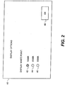
- a structure for providing a display white point which includes any apparatus for providing a white point signal 16 for specifying a display white point to the controller 20.
- this structure includes a user menu that is provided on the EL display 2, and a user input device for selecting between or among display white point options.
- FIG. 2 shows one such menu 40.
- the user is given multiple options 42, 44, 46 for selecting display white points. These options will commonly indicate a single selected option 42 and allow the user to use an input device, such as a mouse or a button to select one of the remaining options 44, 46.
- the user can also be given access to a separate control 48 for indicating that they have indicated their desired preference. These options are provided through a graphical user interface as shown in FIG.
- the display can have a single button, which when pressed, changes the color temperature of the white point of the display.
- the menu 40 shown in FIG. 2 permits the user to explicitly select a color temperature, this explicit control is not necessary and in an alternative arrangement the user is provided with alternate options that allow the implicit control of white point selection, for example, by providing options such as cinema mode (inferring 6500K) and saturated color mode (inferring 9300K).
- the structure for providing a display white point in other arrangements is a signal associated with the input image signal 18. For example, in some arrangements a video signal is encoded assuming a particular display white point. This display white point is encoded in metadata associated with this video signal.
- the video signal is provided to the display, thereby providing the display white point (encoded in the metadata) as well as the input image signal 18. Further, the controller 20 can infer the display white point based upon the source of the input image signal 18. For example an input image signal 18 provided through a standard video port (e.g., a S-video port) might be assumed to have a display white point, such as 6500K but an input image signal 18 provided through a port more closely associated with a computing platform (e.g., a VGA port) might be assumed to have a different display white point, such as 9300K.
- a standard video port e.g., a S-video port
- a port more closely associated with a computing platform e.g., a VGA port
- the EL display can include an EL display panel, which is formed from an EL emitter for emitting white light together with an array of color filters. Different color filters are employed to form the EL emitters for emitting red, green, blue and the two additional colors of light.
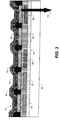
- a cross-section of one such display panel is shown in FIG. 3 .
- the EL display panel 50 will include a substrate 52 on which a drive layer 54 is formed. This drive layer 54 will include electronics, such as active-matrix circuitry, to provide current to each light-emitter.
- Narrowband color filters 56, 58, 60 are then formed to filter any broadband light emission to form narrowband red, green, and blue light, respectively.
- an additional broadband color filter 62 is formed for providing an additional color of light.
- a second broadband color filter (not shown) can optionally be formed for filtering any broadband light emission to form a second additional color of light, but such a color filter is not necessary.
- a smoothing layer 64 can additionally be provided for reducing variations in thickness in the region of the color filters.
- a first electrode 66 is typically formed inside the area defined by each of the color filters and an insulator 68 is typically formed between segments of the electrode to reduce shorting.
- An EL emissive layer 70 can then be formed over the first electrodes for emitting broadband light.
- This EL emissive layer 70 will typically include a multi-layer stack that will typically include at least a hole transport layer, a light-emitting layer, and an electron transport layer.
- the light-emitting layer 70 will typically include multiple species of light-emitting structures or molecules, each species emitting a narrowband of light with a variable wavelength for forming the broadband light emission.
- a second electrode 72 will be formed on the opposite side of the EL emissive layer as the first electrode 66. During operation, the first and second electrodes 66, 72 will provide an electrical potential, motivating the flow of current through the EL emissive layer 70 and the EL emissive layer 70 will emit broadband light in response to the current that passes through this layer.
- the second electrode 72 will typically be formed from a reflective metal, such as aluminum.
- the first electrode 66 will typically be formed from a transparent oxide, such as Indium Tin Oxide and the light emitted by the EL emissive layer 70 will typically be emitted in the direction 74 indicated by the arrow. However, this is not required as the color filters can be formed on the opposite side of the second electrode 72 and the second electrode 72 can be transparent or semi-transparent and the first electrode 66 can be reflective.
- the individual EL emitters within the EL display 50 depicted as 6, 8,10, 12, and 14 of FIG.
- this device includes color filters 56, 58, 60 for each of the three gamut defining emitters and a color filter 62 for one of the two additional emitters.
- the broadband light provided by the EL emissive layer 70 can provide a spectrum, such as 80 in FIG. 4 .
- One of the additional EL emitters 12, 14 in FIG. 1 can emit this light without a color filter, provided the spectrum of light is such that it has chromaticity coordinates that are inside the gamut of the gamut-defining EL emitters 6 , 8 , 10 and near the Planckian Locus.
- Light having the spectrum 80 shown in FIG. 4 will have chromaticity coordinates 0.326, 0.346, which have an Euclidean distance of 0.005 from the Planckian Locus at a correlated color temperature of 5800 Kelvin.
- the second additional EL emitter 12,14 will include some form of color filter. This color filter, for example 62 in FIG.
- FIG. 3 is a dye or pigment based color filter having a spectrum 82 in FIG. 4 .
- this filter can be formed through the design of optical interference within the layers of the device or other known structures.
- Employing a color filter having the spectrum 82, in combination with the EL spectrum 80 shown in FIG. 4 will result in an EL emitter having the spectrum 84.
- Light having the spectrum 84 will have chromaticity coordinates 0.275, 0.290, which have a Euclidean distance of 0.0016 from the Planckian Locus at a correlated color temperature of 10,500 Kelvin.
- the resulting EL display will provide EL emitters for producing colors having the 1931 CIE chromaticity coordinates provided in FIG. 5 .
- the corresponding gamut-defining EL emitters produce light having chromaticity coordinates 90, 92, and 94 for the red, green, and blue EL emitters. These coordinates define a color gamut 96, which specifies the colors that can be formed through combinations of these three colors of light.
- FIG. 5 also shows a portion of the Planckian locus 98 for color temperatures between 5000 and 25000 Kelvin.
- the chromaticity coordinates 100 and 102 provided by light having the spectrum 80 and 84, respectively are also shown and provide pseudo-blackbody points according to the present invention.
- These pseudo-blackbody points besides lying inside the gamut provided by the gamut-defining primaries are near the Planckian Locus, also have correlated color temperatures that differ by more than 2000 Kelvin with one of the pseudo-blackbody points of one of the additional emitters having a correlated color temperature of 6500 Kelvin or less and the second pseudo-blackbody point of the second of the additional emitters having a correlated color temperature of 8000 Kelvin or greater.
- narrow bandpass filters filter the gamut-defining primaries
- these narrow bandpass filters reduce their final radiant efficiency significantly.
- the red, green, and blue EL emitters have radiant efficiencies of 0.00225, 0.00163, and 0.00220 W/A.
- the additional EL emitters are not filtered or are filtered using a broadband filter, they have significantly higher radiant efficiencies, having radiant efficiencies of 0.00642 and 0.0122 W/A. Therefore, each EL emitter has a respective radiant efficiency and the radiant efficiencies of the two additional emitters are each higher than all of the respective radiant efficiencies of the gamut-defining EL emitters.
- the EL emissive layer 70 within the EL display 50 was assumed to have spectral emission 80 with a low correlated color temperature and a color filter 62 was used to alter the emitted light such to achieve a higher color temperature.
- a system of the present invention is formed using an emitter that natively has a high correlated color temperature with a color filter to obtain a lower correlated color temperature.
- FIG. 6 provides an emitter spectrum 110 for an EL emitter having a high correlated color temperature, specifically 8000 Kelvin, and the spectrum of a filter 112 for reducing the short wavelength energy from the emitter spectrum 110.
- the filtered emitter spectrum 114 is obtained for an EL emitter in combination with the color filter having the color filter spectrum 112 with a correlated color temperature of 4900 Kelvin.
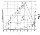
- the chromaticity coordinates shown in FIG. 7 is obtained.
- typical color filters together with the emitter spectrum 110 will result in red, green, and blue emission having the chromaticity coordinates 120, 122, 124, which form the color gamut 126.
- the chromaticity coordinates 130 are obtained and the unfiltered EL emission having the spectrum 110 will provide the chromaticity coordinates 132, each of which are near the Planckian Locus 128.
- the Euclidean distance of the unfiltered emitter has a distance of 0.020 from the Planckian Locus and the filtered emitter has a distance of 0.0012 from the Planckian Locus.
- the resulting EL emitters have relative radiant efficiencies of 0.0099, 0.0104, and 0.0156 W/A for the gamut defining EL emitters and 0.073 and 0.0366 W/A for the additional EL emitters.
- an EL display panel 140 is formed from an EL emitter for emitting white light together with an array of color filters. As shown, different color filters are employed to form the EL emitters for emitting red, green, and blue light. In other arrangements, the color of the additional EL emitters are, however, formed using other methods, such as by tuning the length of optical cavities within the EL display panel 140. As shown, the EL display panel 140 will typically include a substrate 142 on which a drive layer 144 is formed. This drive layer 144 will include electronics, such as active-matrix circuitry, to provide current to each elemental emitter. A first electrode 146 is formed with an insulator 148 between segments of the electrode to reduce shorting.
- variable-thickness, non-emitting layer 166 is formed over the first electrode 146.
- This variable-thickness, non-emitting layer will be relatively transparent and will have a different thickness in the first additional EL emitter, for example the one indicated by region 168, than in the second additional EL emitter, for example the one indicated by region 170.
- the purpose of this variable-thickness, non-emitting layer 166 is to introduce a different optical cavity length within the optical structure of the EL display device.
- An EL emissive layer 150 can then be formed over the first electrodes and the variable-thickness, non-emitting layer 166 for emitting broadband light.
- This EL emissive layer 150 will typically include a multi-layer stack that will typically include at least a hole transport layer, a light-emitting layer, and an electron transport layer.
- the light-emitting layer within the EL emissive layer 150 will typically include multiple species of light-emitting structures or molecules, each species emitting a narrowband of light with a variable wavelength for forming the broadband light emission.
- a second electrode 152 will be formed on the opposite side of the EL emissive layer as the first electrode 146.
- the first and second electrodes 146, 152 will provide an electrical potential, motivating the flow of current through the EL emissive layer 150 and the EL emissive layer 150 will emit broadband light in response to the current that passes through this layer.
- the second electrode 152 will typically be formed from a transparent or semi-transparent material, including materials such as Indium Tin Oxide or thin silver.
- the first electrode 146 will typically be formed from a reflective metal, such as Aluminum.
- the device can then be designed to include a low optical index layer, 176, for example an air gap above the second electrode 152 within the regions of light emission. This low optical index layer 176 is formed, for example, by applying a second substrate 162 above the second electrode 152.
- This second substrate 162 is made to include narrow band color filters 154, 156, and 158 for filtering the broadband light emitted from the light-emitting layer 150 together with a smoothing layer 160 in this arrangement.
- the narrowband color filters 154,156,158 filter broadband light emission to provide red, green, and blue light.
- Narrowband color filters 154, 156, 158 are then formed to filter any broadband light emission to form narrowband red, green, and blue light, respectively.
- a second broadband color filter (not shown) can optionally be formed for filtering any broadband light emission to form one or both of the additional EL emitters, but such a color filter is not necessary.
- variable-thickness, non-emitting layer 166 By selecting the thickness of this variable-thickness, non-emitting layer, the optical cavity length for each EL emitter is designed to preferentially emit certain wavelengths of light as compared to others. Within a device of the present invention, the optical cavity length will be selected by changing the thickness of this variable thickness, non-emitting layer 166 such that a first of the additional EL emitters, such as the one indicated by region 170, preferentially emits short wavelength light. The second of the additional EL emitters preferentially emits medium or long wavelength light.
- the optical cavity length is the distance from the top of the first electrode 146 (ie., the interface between the first electrode 146 and the EL light-emitting layer 150 ) and the top of the second electrode 152 (i.e., the interface between the second electrode layer 152 and low optical index layer 176.
- this non-emitting layer 166 has a different thickness in the first additional EL emitter region 168 than the second additional EL emitter region 170.
- this non-emitting layer 166 is a transparent inorganic conductor.
- a metal oxide, such as Indium Tin Oxide is patterned on top of the first electrode 146 using known methods to form this variable-thickness non-emitting layer 166.
- this variable-thickness non-emitting layer 166 is an organic semiconductor, such as NPB, which is patterned through a shadowmask or through laser transfer techniques.
- this variable thickness non-emitting layer 166 is an inorganic semiconductor.
- this variable-thickness non-emitting layer 166 By varying the thickness of this variable-thickness non-emitting layer 166 between the first and second additional EL emitter regions 168,170, it is possible to provide two additional colors of light having chromaticity coordinates specifying pseudo-blackbody points according to the present invention. It is further advantageous, however, to also vary the thickness of this layer 166 among the EL emitters for emitting red, green, and blue light.
- the efficiency of the red, green, and blue EL emitters is improved when the thickness of the non-emitting layer 166 within the gamut-defining EL emitter for forming blue light, indicated by region 174 is closer to the thickness of the non-emitting layer 166 within the additional EL emitter with the higher color temperature, indicated by region 170, than to the thickness of the non-emitting layer within the additional EL emitter with the lower color temperature.
- the formation of an EL emitter having a higher color temperature is achieved by designing the cavity length to preferentially emit short wavelength light, particularly light having a wavelength of 420 nm or lower.
- the thickness of the variable thickness, non-emitting layer within the gamut-defining EL emitter for emitting blue colored light will be equal to the thickness of the non-emitting layer within the first additional EL emitter region 168.
- the thickness of the non-emitting layer within the gamut-defining EL emitter for forming red or green light, indicated by region 172a, 172b is further useful for the thickness of the non-emitting layer within the gamut-defining EL emitter for forming red or green light, indicated by region 172a, 172b to be closer to the thickness of the non-emitting layer within the additional EL emitter, indicated by region 168, with the lower color temperature than to the thickness of the non-emitting layer within the additional EL emitter with the higher color temperature.
- the formation of an EL emitter with a lower color temperature is obtained by designing the cavity length to preferentially emit medium or long wavelength light, particularly light having a wavelength between 500 and 600 nm.
- the thickness of the non-emitting layer within the gamut-defining EL emitter for emitting red or green colored light will be equal to the thickness of the non-emitting layer within the second additional EL emitter region 170.
- the thickness of the non-emitting layer within both the regions 172a, 172b of the gamut-defining EL emitters for emitting red and green colored light will be equal to the thickness of the non-emitting layer within the second additional EL emitter 170.
- the device shown in FIG. 8 employs a top-emitting structure for emitting light in the direction opposite the substrate. However, this is not necessary and the variable thickness non-emitting layer 166 is employed in bottom emitting structures to achieve some arrangements of an EL display of the present invention. Although, it is sometimes simpler to include a very low optical index layer 176 in an appropriate location within a top-emitting EL device as shown in FIG. 8 , it is not necessary for the low optical index layer 176 to have an optical index as low as air since only a relatively small color change is required between the first and second additional EL emitter regions 168,170 of the present invention.
- the inclusion of solid-state materials within layers of the device is useful in forming the low optical index layer 176 as long as the optical index of these materials is lower than the optical index of the light-emitting layer 150.
- materials typically formed within the drive layer 144 can provide the low optical index layer 176.
- this controller 20 is responsive to the provided display white point, which is provided in signal 16 and the input image signal 18 for providing first separate drive signals 22 for the three gamut-defining EL emitters 6,8,10 and second separate drive signals 24 for the two additional EL emitters 12,14, wherein the respective luminance values corresponding to the second separate drive signals are each a function of the input image signal and the distances between the display white point and the pseudo-blackbody points of the two additional EL emitters 12,14.
- the controller will provide second separate drive signals such that the additional EL emitter having a pseudo-blackbody point closest to the chromaticity coordinates of the provided display white point has a higher luminance value than the additional emitter having the pseudo-blackbody point furthest from the chromaticity coordinates of the provided display white point.
- the controller 20 can employ numerous methods to achieve this result.
- the controller 180 includes a receive input image signal unit 184 for receiving the input image signal 182. This unit can perform any basic decoding steps, such as decompressing the input image signal 182 and converting the input image signal 182 to a three-color channel linear intensity using methods that are well known in the art.
- a receive white point unit 188 is also provided to receive a signal 186 indicating the color of the desired display white point. Based upon the desired display white point, the selected adaptation matrix unit 190, selects a color transform, typically a three by three matrix for rotating the input image signal to the desired display white point.
- the apply adaptation matrix unit 192 then applies this transform to the decoded input image signal to normalize the input image signal to the desired display white point.
- the determine first normalization matrix unit 194 selects an appropriate normalization matrix. During this selection process, the unit 194 determines which of the two additional EL emitters has a pseudo-blackbody point furthest from the chromaticity coordinates of the display white point and selects or computes a matrix to rotate the output of the apply adaptation matrix unit 192 from the display white point to the chromaticity coordinates of the additional EL emitter having a pseudo-blackbody point furthest from the display white point.
- the determined matrix is then applied to the input data stream after application of the adaptation matrix by the apply first normalization matrix unit 196.
- a minimum value of the three color channel is then determined for each pixel in the image signal after application of the first normalization matrix by the determine min unit 198.
- a subtract min unit 200 is then used to subtract the minimum value from the each channel of the three channel signal for each pixel after application of the first normalization matrix. This minimum value is then added to the intensity for an additional color channel corresponding to the EL emitter having a pseudo-blackbody point furthest from the chromaticity coordinates of the desired display white point by the add min unit 202.
- the determine second normalization matrix unit 204 determines a matrix to rotate the color coordinates of the three nonzero color components to the color of the second pseudo-blackbody point.
- the apply second normalization matrix unit 206 then applies this matrix to rotate the color coordinates of the three nonzero color components after the Add Min Unit 202 to the pseudo-blackbody point of the EL emitter having chromaticity coordinates closest to the chromaticity coordinates of the desired display white point.
- a second determine min unit 208 again determines the minimum of the resulting three nonzero channels for each pixel. This minimum is then subtracted from the signal that is acquired after applying the second normalization matrix unit by the subtract min unit 210.
- An add min unit 212 is then applied to add this minimum value to the fifth color channel corresponding to the EL emitter having chromaticity coordinates nearest the chromaticity coordinates of the display white point 132.
- the two zero values that are provided by the subtract min units 200, 212 together with the nonzero value for the resulting value for the remaining three color channel in the input image signal is then used to form a first drive signal 216 by the form first and second drive signal unit 214.
- the values for the two additional channels are then used to form the second drive signal 218 by the form first and second drive signal unit 214.
- this unit 214 will also apply any transforms necessary to convert the linear intensity values provided by the add min unit 212 to code values, voltages, or currents that are used to drive the EL emitters within the EL display.
- the input image signal is a typical RGB signal having equal R, G, and B values (i.e., the input color is white and therefore corresponds to the provided display white point)
- the pseudo-blackbody point for one of the emitters is equal to or very near the desired display white point
- the first and second drive signals will drive practically all of the display luminance through the EL emitter having a pseudo-blackbody point that is near or equal to the display white point.
- the additional emitter having a pseudo-blackbody point closest to the chromaticity coordinates of the provided display white point produces higher luminance values than the additional emitter having the pseudo-blackbody point furthest from the chromaticity coordinates of the provided display white point.
- the controller can perform additional image processing steps.
- the display white point can have a corresponding luminance value that is either specified or inferred and the controller can adjust the luminance value of the display white point in response to the input image signal.
- the input image signal 182 can contain three color channels for an array of pixels that compose a series of image or video frames.
- the controller 180 can additionally include optional units 220, 222, 224, and 226 as shown in FIG. 10 .
- the determined max unit 220 can determine the maximum non-zero intensity values in each frame for each channel after the add min unit 212 performs its calculations.
- the determine ratio unit 222 can then calculate ratios between the maximum possible intensity values and the maximum non-zero intensity values for each channel in each frame.
- the determine min ratio unit 224 can then determine the minimum of these ratios.
- the scale values unit 226 can scale the intensity values resulting from the add min unit 212 by the minimum ratio as determine by the determine min ratio unit 224. This scale value will always be greater than or equal to 1. Therefore, the controller 180 in FIG. 10 will adjust the luminance value of the display white point for each frame in response to a saturation of the input image signal since images containing bright saturated colors will tend to have lower minimum ratio values. Similar methods for adjusting the luminance value of the display white point in response to the input image signal have been discussed in US Patent Application No. 12/174,085, filed July 16, 2008 entitled "Converting Three-Component To Four-Component Image" to Ronald S. Cok et al hereby included by reference.
- One of the primary advantages of the present invention is that the display consumes similar amounts of power as the white point of the display is modified.
- a display panel having emission similar to that shown in FIG. 6 a display is constructed having only a single additional EL emitter as is known in the prior art for emitting light inside the gamut or with the two additional EL emitters of the present invention. Power for each of these displays is shown in Table 1 as a function of display white point.
- the single white emitter in the RGBW system has a correlated color temperature of 8000 Kelvin. Therefore, when an RGBW display is constructed using this single white emitter, the minimum power of the display occurs for color temperatures near 8000 Kelvin and increases for other color temperatures.
- the power consumption is 3.9 W when the white point of the display is 10,000 Kelvin and increases to 4.35 W when the color temperature of the display is set to 6500 degrees K, increasing by over 10 percent.
- the power increases from only 3.65 W at 10,000K to 3.73W at 6500K, only a 2% change in power. Further the power consumption is lower in general when the second emitter is added, providing 14 percent lower power at the 6500 degree Kelvin condition. 6500 K 7500 K 10,000 K RGBW 4.35 W 4.05 W 3.90 W Inventive Example 3.73 W 3.61 W 3.65 W
- the EL display 302 in FIG. 11 of the present invention is adapted to receive a three-color input image signal 320.
- This EL display 302 includes three gamut-defining EL emitters 306 , 308 , 310 formed on a substrate 304 for emitting red, green, and blue colored light, respectively.
- the chromaticity coordinates of the three gamut-defining EL emitters define a gamut and each EL emitter outputs light at a corresponding luminance value in response to a corresponding drive signal.
- three additional (cyan, magenta, and yellow) EL emitters 316, 314, 312 for respectively emitting cyan, magenta, and yellow light.
- each additional EL emitter 312,314,316 is within the gamut of the gamut-defining primaries 306, 308,310 and has respective chromaticity coordinates.
- a line drawn between the chromaticity coordinates of the cyan EL emitter 316 and the magenta EL emitter 314 will intersect the Planckian Locus to define a first pseudo-blackbody point.
- a line drawn between the chromaticity coordinates of the yellow EL emitter 312 and the chromaticity coordinates of the magenta EL emitter 314 will intersect the Planckian Locus to define a second pseudo-blackbody point.
- the distance between the first and second pseudo-blackbody points along the Planckian Locus will be greater than 2000K.
- Each of the additional EL emitter outputs light at a corresponding luminance value in response to a corresponding drive signal.
- the EL display 302 will further include a structure for providing a display white point in response to a white point signal 322; and a controller 318 responsive to the provided display white point and the input image signal 320 for providing first separate drive signals 324 for the three gamut-defining EL emitters 306 , 308 , 310 and second separate drive signals 326 for the three additional EL emitters 312, 314, 316.
- the respective luminance values corresponding to the second separate drive signals 316 are each a function of the input image signal 320 and the distances between the chromaticity coordinates of the display white point and the first and second pseudo-blackbody points.
- the sum of the luminance values of the additional emitters defining a pseudo-blackbody point closest to the chromaticity coordinates of the provided display white point is higher than the sum of the luminance values of the additional emitters defining a pseudo-blackbody point furthest from the provided display white point.
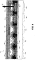
- FIG. 12 shows a cross-section of the display panel within the display of FIG. 11 .
- This display panel 340 includes a substrate 342.
- a drive layer 344 is formed on this substrate.
- Color filters 346, 348, 350, 352, 354 are formed over the substrate and a smoothing layer 356 is applied.
- six EL emitters are formed on the display panel 340 by applying five color filters having different spectra corresponding to the red, green, blue and two of the cyan, magenta and yellow EL emitters.
- Three of these color filters, 346, 348, and 350 are narrowband color filters for forming the gamut-defining primaries of a display of the present invention.
- Two of these color filters 348 and 350 are broadband color filters for filtering broadband light in an efficient manner.
- the display will include corresponding color filters for each of the three gamut-defining EL emitters and exactly two of the three additional EL emitters.
- the first electrodes 358 are formed with insulators 360.
- An EL light-emitting layer 362 is formed over the first electrodes 358 and a second electrode 364 is formed over the EL light-emitting layer 344.
- the light emitted within each EL emitter passes in a direction 366 , as indicated by the arrow.
- the EL emitter without a filter will typically emit light that has a yellow or cyan bias.
- the broadband filters 348, 350 When the EL emitter without a filter emits light that has a yellow bias, the broadband filters 348, 350 will be cyan and magenta filters. When the EL emitter without a filter emits light that has a cyan bias, the broadband filters 348, 350 will be yellow and magenta filters.
- FIG. 13 shows the emission spectrum 380 of a broadband emitter as a function of wavelength.
- This particular emitter has a yellow bias, having chromaticity coordinates of 0.326, 0.346, having a correlated color temperature of about 5800 Kelvin.
- color filter spectra 382, 384 for cyan and magenta color filters, respectively are shown in FIG. 13 which are useful in practicing one arrangement of the present invention. It should be acknowledged, however, that if the emitter had a cyan bias, it would be necessary to include magenta and yellow color filters.
- FIG. 14 provides a 1931 CIE chromaticity diagram including points that are achieved by applying the broadband emitter having the emission spectrum 380, together with narrowband red, green, and blue color filters and the broadband filters having spectra 382 and 384 from FIG. 13 .
- a display panel such as 340 in FIG. 12 , is formed employing these filters which include EL emitters for emitting red, green, and blue light having the chromaticity coordinates 390, 392, and 394.
- the chromaticity coordinates 390, 392, and 394 for the EL emitters form a gamut 396. Inside this gamut are the chromaticity coordinates 398, 400, 402 corresponding to cyan, magenta, and yellow EL emitters, respectively.
- a line 404 is drawn between the chromaticity coordinates 398 of the cyan EL emitter and the chromaticity coordinates 400 of the magenta EL emitter, which intersects the Planckian Locus 408 to define a first pseudo-blackbody point 406.
- This first pseudo-blackbody point 404 lies on the Planckian Locus and has a color temperature of about 19,500 Kelvin.
- a line 410 drawn between the chromaticity coordinates of the yellow EL emitter 402 and the magenta EL emitter 400 intersects the Planckian Locus 408 to define a second pseudo-blackbody point 412, having a color temperature of about 5800 Kelvin.
- the distance between the first and second pseudo-blackbody points along the Planckian Locus is greater than 2000 Kelvin, in fact, in this example, this difference is nearly 14,000 Kelvin.
- the EL display of the present invention that employs the display panel 340 would further include a structure for providing a display white point; and a controller responsive to the provided display white point and the input image signal.
- This controller would provides first separate drive signals for the three gamut-defining EL emitters and second separate drive signals for the three additional EL emitters, wherein the respective luminance values corresponding to the second separate drive signals are each a function of the input image signal and the distances between the chromaticity coordinates of the display white point and the first and second pseudo-blackbody points.
- the controller 180 shown in FIG. 10 can also be employed within this arrangement.
- first and second drive signal unit 214 would transform the intensities for the first and second pseudo-blackbody points to cyan, magenta, and yellow intensity values by multiplying each of these intensity values by two separate weighting values for the cyan, magenta, and yellow intensity values and summing these for each channel. These weighting values simply represent the ratio of each of the EL emitters required to create each of the pseudo-blackbody points.
- This controller can also employ other algorithms for converting red, green, and blue input intensity values to separate signals for driving red, green, and blue gamut defining EL emitters as well as cyan, magenta, and yellow EL emitters as are known in the art.
- FIG. 11 provides a broadband emitter together with three narrowband and two broadband filters
- other arrangements of EL displays are formed which fulfill the requirements of the present invention. This includes displays including various optical cavity configurations and patterning of materials having different color emission.
- the EL display of the present invention includes Organic Light Emitting Diodes (OLEDs), which are composed of small molecule or polymeric OLEDs as disclosed in but not limited to U.S. Pat. No. 4,769,292, by Tang et al. , and U.S. Pat. No. 5,061,569, by VanSlyke et al. Many combinations and variations of organic light emitting materials can be used to fabricate such a panel.
- OLEDs Organic Light Emitting Diodes
Landscapes
- Engineering & Computer Science (AREA)
- Physics & Mathematics (AREA)
- Computer Hardware Design (AREA)
- General Physics & Mathematics (AREA)
- Theoretical Computer Science (AREA)
- Electroluminescent Light Sources (AREA)
- Control Of Indicators Other Than Cathode Ray Tubes (AREA)
- Control Of El Displays (AREA)
Claims (15)
- EL-Anzeige (2), dazu ausgebildet, ein Dreifarbeneingabebildsignal zu empfangen, umfassend:a) drei Gamut definierende EL-Emitter (6, 8, 10) zum Emittieren von rot-, grün- und blau-farbigem Licht und einen ersten (12) und einen zweiten (14) zusätzlichen EL-Emitter zum Emittieren von zwei verschiedenen zusätzlichen Lichtfarben, die Chromatizitätskoordinaten aufweisen, die entsprechende Pseudo-Schwarzkörperpunkte spezifizieren, wobei die Chromatizitätskoordinaten der zwei zusätzlichen Lichtfarben innerhalb eines Gamuts, der durch die drei Gamut definierenden EL-Emitter (6, 8, 10) definiert ist, und innerhalb eines euklidischen Abstands von plus oder minus 0,05 von dem nächsten Punkt auf dem Planckschen Locus liegen, wobei die zwei Pseudo-Schwarzkörperpunkte entsprechende korrelierte Farbtemperaturen aufweisen, die um mindestens 2000K voneinander verschieden sind, und wobei jeder EL-Emitter Licht mit einem entsprechenden Luminanzwert ausgibt in Antwort auf ein entsprechendes Antriebssignal;b) Mittel zum Bereitstellen eines gewünschten Anzeigeweißpunkts, der als Eingabe bereitgestellt ist; undc) ein Steuergerät (20) zum Bereitstellen, in Antwort auf den bereitgestellten Anzeigeweißpunkt und das Dreifarbeneingabebildsignal, von ersten separaten Antriebssignalen für die drei Gamut definierenden EL-Emitter (6, 8, 10) und von zweiten separaten Antriebssignalen für die zwei zusätzlichen EL-Emitter (12, 14), wobei die jeweiligen Luminanzwerte entsprechend den zweiten separaten Antriebssignalen jeweils eine Funktion des Eingabebildsignals und der Abstände zwischen dem gewünschten Anzeigeweißpunkt, der als Eingabe bereitgestellt ist, und den Pseudo-Schwarzkörperpunkten der zwei zusätzlichen Farben ist, wobei das Steuergerät umfasst:eine Eingabebildsignal-Empfangseinheit (184) zum Empfangen des Eingabebildsignals;eine Weißpunkt-Empfangseinheit (188) zum Empfangen eines Signals, das auf den bereitgestellten Anzeigeweißpunkt, der als Eingabe bereitgestellt ist, hinweist;eine Ausgewählte-Adaptationsmatrix-Einheit (190) zum Auswählen, auf der Grundlage des gewünschten Anzeigeweißpunkts, einer Farbtransformation des Eingabebildsignals zu dem gewünschten Anzeigeweißpunkt;eine Adaptationsmatrix-Anwendungseinheit (192) zum Anwenden der Transformation auf das decodierte Eingabebildsignal, um das Eingabebildsignal zu dem gewünschten Anzeigeweißpunkt zu normalisieren;eine Erste-Normalisierungsmatrix-Bestimmungseinheit (194) zum Auswählen, auf der Grundlage des gewünschten Anzeigeweißpunkts, einer geeigneten Normalisierungsmatrix, wobei die Erste-Normalisierungsmatrix-Bestimmungseinheit (194) bestimmt, welcher der zwei zusätzlichen EL-Emitter einen Pseudo-Schwarzkörperpunkt aufweist, der von den Chromatizitätskoordinaten des Anzeigeweißpunkts am weitesten ist, und eine Matrix auswählt oder berechnet, um die Ausgabe der Adaptationsmatrix-Anwendungseinheit (192) von dem Anzeigeweißpunkt zu den Chromatizitätskoordinaten des zusätzlichen EL-Emitters zu rotieren, der einen Pseudo-Schwarzkörperpunkt am weitesten von dem Anzeigeweißpunkt aufweist;eine Erste-Normalisierungsmatrix-Anwendungseinheit (196) zum Anwenden der bestimmten Matrix auf den Eingabedatenstrom nach Anwendung der Adaptationsmatrix;eine erste Min-Bestimmungseinheit (198) zum Bestimmen eines Minimalwerts des Dreifarbenkanals für jeden Pixel in dem Bildsignal nach Anwendung der ersten Normalisierungsmatrix;eine erste Min-Subtraktionseinheit (200) zum Subtrahieren des Minimalwerts von jedem Kanal des Dreikanalsignals für jeden Pixel nach Anwendung der ersten Normalisierungsmatrix;eine erste Min-Additionseinheit (202) zum Addieren des Minimalwerts zu einer Intensität für einen zusätzlichen Farbkanal entsprechend dem EL-Emitter, der einen Pseudo-Schwarzkörperpunkt am weitesten von den Chromatizitätskoordinaten des gewünschten Anzeigeweißpunkt aufweist;eine Zweite-Normalisationsmatrix-Bestimmungseinheit (204) zum Bestimmen einer Matrix, um die Farbkoordinaten der drei Nicht-null-Farbkomponenten zu der Farbe des zweiten Pseudo-Schwarzkörperpunkts zu rotieren;eine Zweite-Normalisierungsmatrix-Anwendungseinheit (206) zum Anwenden der Matrix, um die Farbkoordinaten der drei Nicht-null-Farbkomponenten zu dem Pseudo-Schwarzkörperpunkt des EL-Emitters zu rotieren, der Chromatizitätskoordinaten am nächsten zu den Chromatizitätskoordinaten des gewünschten Anzeigeweißpunkts aufweist;eine zweite Min-Bestimmungseinheit (208) zum Bestimmen des Minimums der resultierenden drei Nicht-null-Kanäle für jeden Pixel;eine zweite Min-Subtraktionseinheit (210) zum Subtrahieren des Minimums von dem Signal, das erhalten wird nach Anwenden der zweiten Normalisierungsmatrixeinheit;eine zweite Min-Additionseinheit (212) zum Addieren des Minimalwerts zu dem fünften Farbkanal entsprechend dem EL-Emitter, der Chromatizitätskoordinaten am nächsten zu den Chromatizitätskoordinaten des Anzeigeweißpunkts aufweist;eine Erstes-und-Zweites-Antriebssignal-Formungseinheit (214) zum Formen eines ersten Antriebssignals unter Verwendung der zwei Nullwerte, die durch die Min-Subtraktionseinheiten (200, 212) bereitgestellt sind, zusammen mit dem Nicht-null-Wert für den resultierenden Wert für die übrigen drei Farbkanäle in dem Eingabebildsignal und zum Formen des zweiten Antriebsignals unter Verwendung der Werte für die zwei zusätzlichen Kanäle.
- EL-Anzeige (2) nach Anspruch 1, bei der, wenn das Eingabebildsignal dem bereitgestellten Anzeigeweißpunkt entspricht, der zusätzliche EL-Emitter, der einen Pseudo-Schwarzkörperpunkt am nächsten zu den Chromatizitätskoordinaten des bereitgestellten Anzeigeweißpunkts aufweist, einen höheren Luminanzwert aufweist als der zusätzliche EL-Emitter, der den Pseudo-Schwarzkörperpunkt am weitesten von den Chromatizitätskoordinaten des bereitgestellten Anzeigeweißpunkts aufweist.
- EL-Anzeige (2) nach Anspruch 1, bei der einer der Pseudo-Schwarzkörperpunkte der zwei zusätzlichen EL-Emitter (12, 14) eine korrelierte Farbtemperatur von 6500K oder weniger aufweist und der zweite eine korrelierte Farbtemperatur von 8000K oder größer aufweist, wobei die korrelierte Farbtemperatur als die Temperatur eines Schwarzkörperstrahlers berechnet ist, der den kleinsten euklidischen Abstand von der Farbe innerhalb des 1976-CIEeinheitlichen Chromatizitätsraums aufweist.
- EL-Anzeige (2) nach Anspruch 1, bei der jeder EL-Emitter eine jeweilige Strahlungseffizienz aufweist und die Strahlungseffizienzen der zwei zusätzlichen EL-Emitter (12, 14) beide höher sind als alle jeweiligen Strahlungseffizienzen der Gamut definierenden EL-Emitter (6, 8, 10), und/oder die EL-Anzeige (2) ferner entsprechende Farbfilter (56, 58, 60, 62) für jeden der drei Gamut definierenden EL-Emitter (6, 8, 10) und einen der zwei zusätzlichen EL-Emitter (12, 14) enthält.
- EL-Anzeige (2) nach Anspruch 1, ferner enthaltend eine nicht emittierende Schicht (166), die eine veränderliche Dicke aufweist, wobei die nicht emittierende Schicht in dem ersten zusätzlichen EL-Emitter eine andere Dicke als in dem zweiten zusätzlichen EL-Emitter aufweist.
- EL-Anzeige (2) nach Anspruch 5, bei der die nicht emittierende Schicht (166) ein transparenter anorganischer Leiter oder ein organischer Halbleiter ist.
- EL-Anzeige (2) nach Anspruch 5, bei der die nicht emittierende Schicht (166) in einem ersten ausgewählten Gamut definierenden EL-Emitter eine andere Dicke als in einem zweiten ausgewählten Gamut definierenden EL-Emitter aufweist.
- EL-Anzeige (2) nach Anspruch 7, bei der der erste zusätzliche EL-Emitter (12) eine höhere korrelierte Farbtemperatur als der zweite zusätzliche EL-Emitter (14) aufweist, wobei die Dicke der nicht emittierenden Schicht (166) innerhalb des Gamut definierenden EL-Emitters (10) zum Emittieren des blaufarbigen Lichts gleich ist wie die Dicke der nicht emittierenden Schicht (166) innerhalb des ausgewählten ersten zusätzlichen EL-Emitters (12), oder die Dicke der nicht emittierenden Schicht (166) innerhalb des Gamut definierenden EL-Emitters (6, 8) zum Emittieren des rot- oder grün-farbigen Lichts gleich ist wie die Dicke der nicht emittierenden Schicht (166) innerhalb des zweiten zusätzlichen EL-Emitters (14), und wobei die korrelierte Farbtemperatur als die Temperatur eines Schwarzkörperstrahlers berechnet ist, der den kleinsten euklidischen Abstand von der Farbe innerhalb des 1976-CIEeinheitlichen Chromatizitätsraums aufweist.
- EL-Anzeige (302), dazu ausgebildet, ein Dreifarbeneingabebildsignal zu empfangen, umfassend:a) drei Gamut definierende EL-Emitter (306, 308, 310) zum Emittieren von rot-, grün- und blau-farbigem Licht, wobei die drei Gamut definierenden EL-Emitter (306, 308, 310) einen Gamut definieren und wobei jeder Gamut definierende EL-Emitter (306, 308, 310) Licht mit einem entsprechenden Luminanzwert ausgibt in Antwort auf ein entsprechendes Antriebssignal;b) cyan, magenta und gelbe zusätzliche EL-Emitter (312, 314, 316) zum jeweiligen Emittieren von cyan, magenta und gelbem Licht, wobei jeder zusätzliche EL-Emitter (312, 314, 316) innerhalb des Gamuts liegt und jeweils Chromatizitätskoordinaten aufweist, die Linie zwischen den Chromatizitätskoordinaten des cyan EL-Emitters (316) und des magenta EL-Emitters (314) den Planckschen Locus schneidet, um einen ersten Pseudo-Schwarzkörperpunkt zu definieren, die Linie zwischen den Chromatizitätskoordinaten des gelben EL-Emitters (312) und des magenta EL-Emitters (314) den Planckschen Locus schneidet, um einen zweiten Pseudo-Schwarzkörperpunkt zu definieren, der Abstand zwischen dem ersten und dem zweiten Pseudo-Schwarzkörperpunkt entlang dem Planckschen Locus größer ist als 2000K, und wobei jeder zusätzliche EL-Emitter (312, 314, 316) Licht mit einem entsprechenden Luminanzwert ausgibt in Antwort auf ein entsprechendes Antriebssignal;c) Mittel zum Bereitstellen eines gewünschten Anzeigeweißpunkt, der als Eingabe bereitgestellt ist; undd) ein Steuergerät (318) zum Bereitstellen, in Antwort auf den bereitgestellten Anzeigeweißpunkt und das Eingabebildsignal, von ersten separaten Antriebssignalen für die drei Gamut definierenden EL-Emitter (306, 308, 310) und von zweiten separaten Antriebssignalen für die drei zusätzlichen EL-Emitter (312, 314, 316), wobei die jeweiligen Luminanzwerte entsprechend den zweiten separaten Antriebssignalen jeweils eine Funktion des Eingabebildsignals und der Abstände zwischen den Chromatizitätskoordinaten des gewünschten Anzeigeweißpunkts, der als Eingabe bereitgestellt ist, und dem ersten und dem zweiten Pseudo-Schwarzkörperpunkt sind, wobei das Steuergerät umfasst:eine Eingabebildsignal-Empfangseinheit (184) zum Empfangen des Eingabebildsignals;eine Weißpunkt-Empfangseinheit (88) zum Empfangen eines Signals, das auf den bereitgestellten Anzeigeweißpunkt, der als Eingabe bereitgestellt ist, hinweist;eine Ausgewählte-Adaptationsmatrix-Einheit (190) zum Auswählen, auf der Grundlage des gewünschten Anzeigeweißpunkts, einer Farbtransformation zum Rotieren des Eingabebildsignals zu dem gewünschten Anzeigeweißpunkt;eine Adaptationsmatrix-Anwendungseinheit (192) zum Anwenden der Transformation auf das decodierte Eingabebildsignal, um das Eingabebildsignal zu dem gewünschten Anzeigeweißpunkt zu normalisieren;eine Erste-Normalisierungsmatrix-Bestimmungseinheit (194) zum Auswählen, auf der Grundlage des gewünschten Anzeigeweißpunkts, einer geeigneten Normalisierungsmatrix, wobei die Erste-Normalisierungsmatrix-Bestimmungseinheit (194) bestimmt, welcher der zwei Pseudo-Schwarzkörperpunkte am weitesten von Chromatizitätskoordinaten des gewünschten Anzeigeweißpunkts, der als Eingabe bereitgestellt ist, liegt, und eine Matrix auswählt oder berechnet, um die Ausgabe der Adaptationsmatrix-Anwendungseinheit (192) von dem Anzeigeweißpunkt zu den Chromatizitätskoordinaten des Pseudo-Schwarzkörperpunkts zu rotieren, der am weitesten von dem Anzeigeweißpunkt liegt;eine Erste-Normalisierungsmatrix-Anwendungseinheit (196) zum Anwenden der bestimmten Matrix auf den Eingabedatenstrom nach Anwendung der Adaptationsmatrix;eine erste Min-Bestimmungseinheit (198) zum Bestimmen eines Minimalwerts der drei Farbkanäle für jeden Pixel in dem Bildsignal nach Anwendung der ersten Normalisierungsmatrix;eine erste Min-Subtraktionseinheit (200) zum Subtrahieren des Minimalwerts von jedem Kanal des Dreikanalsignals für jeden Pixel nach Anwendung der ersten Normalisierungsmatrix;eine erste Min-Additionseinheit (202) zum Addieren des Minimalwerts zu einer Intensität für einen ersten zusätzlichen Farbkanal entsprechend dem Pseudo-Schwarzkörperpunkt, der am weitesten von den Chromatizitätskoordinaten des gewünschten Anzeigeweißpunkts liegt;eine Zweite-Normalisierungsmatrix-Bestimmungseinheit (204) zum Bestimmen einer Matrix, um die Farbkoordinaten der drei Nicht-null-Farbkomponenten zu der Farbe des zweiten Pseudo-Schwarzkörperpunkts zu rotieren;eine Zweite-Normalisierungsmatrix-Anwendungseinheit (206) zum Anwenden der Matrix, um die Farbkoordinaten der drei Nicht-null-Farbkomponenten zu dem Pseudo-Schwarzkörperpunkt zu rotieren, der Chromatizitätskoordinaten am nächsten zu den Chromatizitätskoordinaten des gewünschten Anzeigeweißpunkts aufweist;eine zweite Min-Bestimmungseinheit (208) zum Bestimmen des Minimums der resultierenden drei Nicht-null-Kanäle für jeden Pixel;eine zweite Min-Subtraktionseinheit (210) zum Subtrahieren des Minimums von dem Signal, das erhalten ist nach Anwendung der zweiten Normalisierungsmatrix-Einheit;eine zweite Min-Additionseinheit (212) zum Addieren des Minimalwerts zu einer Intensität für einen zweiten zusätzlichen Farbkanal entsprechend dem Pseudo-Schwarzkörperpunkt, der Chromatizitätskoordinaten am nächsten den Chromatizitätskoordinaten des gewünschten Anzeigeweißpunkts, der als Eingabe bereitgestellt ist, aufweist, undeine Erstes-und-Zweites-Antriebssignal-Formungseinheit (214) zum Formen eines ersten Antriebsignals unter Verwendung der zwei Nullwerte, die bereitgestellt sind durch die Min-Subtraktionseinheiten (200, 212), zusammen mit dem Nicht-nullWert für den resultierenden Wert für den übrigen Dreifarbkanal in dem Eingabebildsignal und zum Formen des zweiten Antriebsignals durch Transformieren der Intensitäten für den ersten und den zweiten zusätzlichen Farbkanal entsprechend dem ersten und dem zweiten Pseudo-Schwarzkörperpunkt zu cyan, magenta und gelben Intensitätswerten durch Multiplizieren jedes dieser Intensitätswerte mit zwei separaten Gewichtungswerten für die cyan, magenta und gelben Intensitätswerte und Summieren dieser für jeden Kanal, wobei die Gewichtungswerte ein Verhältnis jedes der zusätzlichen EL-Emitters darstellt, das erforderlich ist, um jeden der Pseudo-Schwarzkörperpunkte zu erzeugen.
- EL-Anzeige (302) nach Anspruch 9, bei der, wenn das Eingabebildsignal dem bereitgestellten Anzeigeweißpunkt entspricht, die Summe der Luminanzwerte der zusätzlichen EL-Emitter (312, 314, 316), die einen Pseudo-Schwarzkörperpunkt am nächsten zu den Chromatizitätskoordinaten des bereitgestellten Anzeigeweißpunkts definieren, höher ist als die Summe der Luminanzwerte der zusätzlichen EL-Emitter (312, 314, 316), die einen Pseudo-Schwarzkörperpunkt am weitesten von dem bereitgestellten Anzeigeweißpunkt definieren.
- EL-Anzeige (302) nach Anspruch 9, bei der der zweite Pseudo-Schwarzkörperpunkt eine korrelierte Farbtemperatur von 6500K oder weniger aufweist und der erste Pseudo-Schwarzkörperpunkt eine korrelierte Farbtemperatur von 8000K oder größer aufweist, wobei die korrelierte Farbtemperatur als die Temperatur eines Schwarzkörperstrahlers berechnet ist, der den kleinsten euklidischen Abstand von der Farbe innerhalb des 1976-CIE-einheitlichen Chromatizitätsraums aufweist.
- EL-Anzeige (302) nach Anspruch 9, bei der jeder EL-Emitter eine jeweilige Strahlungseffizienz aufweist und die Strahlungseffizienzen der drei zusätzlichen EL-Emitter (312, 314, 316) alle höher sind als die jeweiligen Strahlungseffizienzen der Gamut definierenden EL-Emitter (306, 308, 310).
- EL-Anzeige (302) nach Anspruch 9, ferner umfassend entsprechende Farbfilter für jeden der drei Gamut definierenden EL-Emitter (306, 308, 310) und genau zwei der drei zusätzlichen EL-Emitter (312, 314, 316).
- EL-Anzeige (2; 302) nach Anspruch 1 oder 9, bei der der Anzeigeweißpunkt einen entsprechenden Luminanzwert aufweist und das Steuergerät (20; 318) den Luminanzwert des Anzeigeweißpunkts in Antwort auf das Eingabebildsignal einstellt.
- EL-Anzeige (2; 302) nach Anspruch 5 oder 14, bei der das Steuergerät (20; 318) den Luminanzwert des Anzeigeweißpunkts in Antwort auf eine Saturierung des Eingabebildsignals einstellt.
Applications Claiming Priority (2)
| Application Number | Priority Date | Filing Date | Title |
|---|---|---|---|
| US12/464,123 US8237633B2 (en) | 2009-05-12 | 2009-05-12 | Electro-luminescent display with adjustable white point |
| PCT/US2010/034019 WO2010132295A1 (en) | 2009-05-12 | 2010-05-07 | Electro-luminescent display with additional primaries and adjustable white point |
Publications (2)
| Publication Number | Publication Date |
|---|---|
| EP2430630A1 EP2430630A1 (de) | 2012-03-21 |
| EP2430630B1 true EP2430630B1 (de) | 2017-04-26 |
Family
ID=42315642
Family Applications (1)
| Application Number | Title | Priority Date | Filing Date |
|---|---|---|---|
| EP10722869.4A Active EP2430630B1 (de) | 2009-05-12 | 2010-05-07 | Elektrolumineszenzanzeige mit zusätzlichen primärfarben und regelbarem weisspunkt |
Country Status (7)
| Country | Link |
|---|---|
| US (1) | US8237633B2 (de) |
| EP (1) | EP2430630B1 (de) |
| JP (1) | JP5426020B2 (de) |
| KR (1) | KR101270187B1 (de) |
| CN (1) | CN102422341B (de) |
| TW (1) | TWI376668B (de) |
| WO (1) | WO2010132295A1 (de) |
Families Citing this family (31)
| Publication number | Priority date | Publication date | Assignee | Title |
|---|---|---|---|---|
| US8466856B2 (en) * | 2011-02-22 | 2013-06-18 | Global Oled Technology Llc | OLED display with reduced power consumption |
| KR101065321B1 (ko) * | 2010-03-03 | 2011-09-16 | 삼성모바일디스플레이주식회사 | 유기전계발광 표시장치 및 그 구동방법 |
| JP5593920B2 (ja) * | 2010-07-27 | 2014-09-24 | ソニー株式会社 | 液晶表示装置 |
| US8829822B2 (en) * | 2010-09-08 | 2014-09-09 | Osram Sylvania Inc. | LED-based light source having decorative and illumination functions |
| TWI505524B (zh) * | 2011-05-20 | 2015-10-21 | Au Optronics Corp | 有機電激發光光源 |
| KR102758672B1 (ko) * | 2011-05-27 | 2025-01-22 | 돌비 레버러토리즈 라이쎈싱 코오포레이션 | 변하는 레벨들의 메타데이터을 포함하는 컬러 관리를 제어하기 위한 스케일러블 시스템들 |
| US8502445B2 (en) * | 2011-07-18 | 2013-08-06 | Universal Display Corporation | RGBW OLED display for extended lifetime and reduced power consumption |
| KR101407309B1 (ko) * | 2011-11-15 | 2014-06-16 | 엘지디스플레이 주식회사 | 유기 전계 발광 표시 패널 및 그의 제조 방법 |
| KR20140074243A (ko) | 2012-12-07 | 2014-06-17 | 주식회사 엘지화학 | 조명 기구 및 이의 제조방법 |
| US8988340B2 (en) | 2013-03-16 | 2015-03-24 | VIZIO Inc. | Controlling color and white temperature in an LCD display modulating supply current frequency |
| US9208750B2 (en) * | 2013-05-13 | 2015-12-08 | Asustek Computer Inc. | Color temperature adjusting method of display device |
| US9762868B2 (en) * | 2013-06-28 | 2017-09-12 | Thomson Licensing | Highlighting an object displayed by a pico projector |
| US9990899B2 (en) | 2013-09-06 | 2018-06-05 | Mitsubishi Electric Corporation | Image display apparatus combining three-in-one with single color light-emitting elements |
| TWI515891B (zh) | 2013-11-01 | 2016-01-01 | 友達光電股份有限公司 | 顯示面板 |
| FR3013846A1 (fr) | 2013-11-22 | 2015-05-29 | Jacques Degroote | Methode de marquage chimique de lots de dioxyde de carbone en vue d'en assurer la tracabilite |
| WO2015174276A1 (ja) * | 2014-05-12 | 2015-11-19 | シャープ株式会社 | 画像表示装置 |
| CN104319352B (zh) * | 2014-11-13 | 2018-02-13 | 京东方科技集团股份有限公司 | 一种顶发射白光oled器件及其制备方法、显示装置 |
| DE102016102596A1 (de) | 2016-02-15 | 2017-08-17 | Osram Opto Semiconductors Gmbh | Verfahren zum Betreiben einer Halbleiterlichtquelle und Halbleiterlichtquelle |
| CN106023818B (zh) * | 2016-05-18 | 2019-09-17 | 京东方科技集团股份有限公司 | 一种像素结构、显示面板及像素结构的驱动方法 |
| CN106486074B (zh) * | 2016-11-01 | 2019-04-02 | 深圳市华星光电技术有限公司 | 多基色石墨烯显示器的显示方法 |
| US10482843B2 (en) * | 2016-11-07 | 2019-11-19 | Qualcomm Incorporated | Selective reduction of blue light in a display frame |
| US10600385B2 (en) * | 2016-11-11 | 2020-03-24 | Dell Products, Lp | System and method for contextually managing digital display blue light intensity |
| US11689084B2 (en) | 2017-07-27 | 2023-06-27 | Flekkefjord Elektro As | Electromotor having integrated inverter |
| US10353243B2 (en) * | 2017-08-01 | 2019-07-16 | Innolux Corporation | Display device |
| US20190041701A1 (en) * | 2017-08-01 | 2019-02-07 | Innolux Corporation | Display device |
| KR20250038812A (ko) | 2018-05-11 | 2025-03-19 | 가부시키가이샤 한도오따이 에네루기 켄큐쇼 | 표시 장치, 표시 모듈, 및 전자 기기 |
| CN108682407B (zh) * | 2018-06-14 | 2020-04-14 | 业成科技(成都)有限公司 | 自动化色温调整方法 |
| JP7656602B2 (ja) * | 2019-11-07 | 2025-04-03 | シグニファイ ホールディング ビー ヴィ | 色空間におけるプランク軌跡に従う特定の放射光を発するよう構成される発光ダイオード(led)ベースの照明デバイス |
| KR102867201B1 (ko) * | 2021-01-26 | 2025-10-01 | 삼성디스플레이 주식회사 | 디스플레이 장치 |
| CN113257174B (zh) * | 2021-04-26 | 2022-07-12 | 长春希达电子技术有限公司 | 一种led显示屏色度校正目标色域的确定方法 |
| WO2026070481A1 (ja) * | 2024-09-30 | 2026-04-02 | ソニーグループ株式会社 | 表示装置 |
Citations (1)
| Publication number | Priority date | Publication date | Assignee | Title |
|---|---|---|---|---|
| JP2008071664A (ja) * | 2006-09-15 | 2008-03-27 | Seiko Epson Corp | 電気光学装置及び電子機器 |
Family Cites Families (24)
| Publication number | Priority date | Publication date | Assignee | Title |
|---|---|---|---|---|
| KR850000958B1 (ko) | 1981-02-10 | 1985-06-29 | 야마시다 도시히꼬 | 화상표시장치 |
| US4769292A (en) | 1987-03-02 | 1988-09-06 | Eastman Kodak Company | Electroluminescent device with modified thin film luminescent zone |
| US5061569A (en) | 1990-07-26 | 1991-10-29 | Eastman Kodak Company | Electroluminescent device with organic electroluminescent medium |
| US7320594B1 (en) * | 1995-08-31 | 2008-01-22 | Biolase Technology, Inc. | Fluid and laser system |
| US6366270B1 (en) | 1998-05-29 | 2002-04-02 | Silicon Graphics, Inc. | Multiple light source color balancing system within a liquid crystal flat panel display |
| AU2000250291A1 (en) * | 2000-02-10 | 2001-08-20 | Telogy Networks, Inc. | A generalized precoder for the upstream voiceband modem channel |
| EP1373794A1 (de) | 2001-02-19 | 2004-01-02 | Koninklijke Philips Electronics N.V. | Beleuchtungssystem und anzeigevorrichtung |
| US20040264193A1 (en) * | 2001-08-23 | 2004-12-30 | Yukiyasu Okumura | Color temperature-regulable led light |
| AU2003253179A1 (en) * | 2002-10-18 | 2004-05-04 | Koninklijke Philips Electronics N.V. | Full-color organic electro-luminescent display device |
| US7230594B2 (en) | 2002-12-16 | 2007-06-12 | Eastman Kodak Company | Color OLED display with improved power efficiency |
| US6897876B2 (en) * | 2003-06-26 | 2005-05-24 | Eastman Kodak Company | Method for transforming three color input signals to four or more output signals for a color display |
| JP2005062833A (ja) * | 2003-07-29 | 2005-03-10 | Seiko Epson Corp | カラーフィルタ、カラー画像表示装置および電子機器 |
| US6870323B1 (en) * | 2003-10-02 | 2005-03-22 | Eastman Kodak Company | Color display with white light emitting elements |
| TWI263356B (en) * | 2003-11-27 | 2006-10-01 | Kuen-Juei Li | Light-emitting device |
| KR101012790B1 (ko) * | 2003-12-30 | 2011-02-08 | 삼성전자주식회사 | 4색 표시 장치의 영상 신호 변환 장치 및 방법, 그리고이를 포함하는 표시 장치 |
| US7301543B2 (en) * | 2004-04-09 | 2007-11-27 | Clairvoyante, Inc. | Systems and methods for selecting a white point for image displays |
| KR101058093B1 (ko) * | 2004-07-09 | 2011-08-24 | 삼성전자주식회사 | 유기전계발광 표시장치 |
| JP2007141737A (ja) | 2005-11-21 | 2007-06-07 | Sharp Corp | 照明装置、液晶表示装置、照明装置の制御方法、照明装置制御プログラム、および記録媒体 |
| EP1963740A4 (de) * | 2005-12-21 | 2009-04-29 | Cree Led Lighting Solutions | Beleuchtungsvorrichtung und beleuchtungsverfahren |
| KR20080009497A (ko) * | 2006-07-24 | 2008-01-29 | 삼성전자주식회사 | 다색 표시 장치 및 그 구동 방법 |
| US20080252797A1 (en) * | 2007-04-13 | 2008-10-16 | Hamer John W | Method for input-signal transformation for rgbw displays with variable w color |
| US7772757B2 (en) * | 2007-05-30 | 2010-08-10 | Eastman Kodak Company | White-light electro-luminescent device with improved efficiency |
| CN101663702B (zh) | 2007-06-25 | 2013-05-08 | 夏普株式会社 | 彩色显示装置的驱动控制电路及驱动控制方法 |
| CN101821544B (zh) * | 2007-10-10 | 2012-11-28 | 科锐公司 | 照明装置及制造方法 |
-
2009
- 2009-05-12 US US12/464,123 patent/US8237633B2/en active Active
-
2010
- 2010-05-07 WO PCT/US2010/034019 patent/WO2010132295A1/en not_active Ceased
- 2010-05-07 EP EP10722869.4A patent/EP2430630B1/de active Active
- 2010-05-07 JP JP2012510876A patent/JP5426020B2/ja active Active
- 2010-05-07 KR KR1020117029542A patent/KR101270187B1/ko active Active
- 2010-05-07 CN CN201080020818XA patent/CN102422341B/zh active Active
- 2010-05-10 TW TW099114855A patent/TWI376668B/zh active
Patent Citations (1)
| Publication number | Priority date | Publication date | Assignee | Title |
|---|---|---|---|---|
| JP2008071664A (ja) * | 2006-09-15 | 2008-03-27 | Seiko Epson Corp | 電気光学装置及び電子機器 |
Also Published As
| Publication number | Publication date |
|---|---|
| KR101270187B1 (ko) | 2013-06-04 |
| WO2010132295A1 (en) | 2010-11-18 |
| US20100289727A1 (en) | 2010-11-18 |
| JP5426020B2 (ja) | 2014-02-26 |
| CN102422341A (zh) | 2012-04-18 |
| CN102422341B (zh) | 2013-05-08 |
| TWI376668B (en) | 2012-11-11 |
| JP2012527011A (ja) | 2012-11-01 |
| TW201101276A (en) | 2011-01-01 |
| US8237633B2 (en) | 2012-08-07 |
| KR20120017066A (ko) | 2012-02-27 |
| EP2430630A1 (de) | 2012-03-21 |
Similar Documents
| Publication | Publication Date | Title |
|---|---|---|
| EP2430630B1 (de) | Elektrolumineszenzanzeige mit zusätzlichen primärfarben und regelbarem weisspunkt | |
| KR101191798B1 (ko) | Oled 디바이스 | |
| EP2404290B1 (de) | Reduzierung des stromverbrauchs einer vierkanalanzeige mit desaturierung | |
| JP5885272B2 (ja) | 電力消費を低減したoledディスプレイ上に画像を表示するための方法 | |
| CN101821851B (zh) | 具有改善的光输出的led设备 | |
| EP2321818B1 (de) | Verfahren zur verbesserung der display-lebensdauer | |
| KR101419247B1 (ko) | 백색 유기 발광 소자 및 이를 이용한 표시 장치 | |
| KR20100087707A (ko) | 보색 서브픽셀을 갖는 led 디바이스 | |
| US20090051642A1 (en) | Backlight assembly, method of driving the same and display system having the same thereof |
Legal Events
| Date | Code | Title | Description |
|---|---|---|---|
| PUAI | Public reference made under article 153(3) epc to a published international application that has entered the european phase |
Free format text: ORIGINAL CODE: 0009012 |
|
| 17P | Request for examination filed |
Effective date: 20111026 |
|
| AK | Designated contracting states |
Kind code of ref document: A1 Designated state(s): AL AT BE BG CH CY CZ DE DK EE ES FI FR GB GR HR HU IE IS IT LI LT LU LV MC MK MT NL NO PL PT RO SE SI SK SM TR |
|
| DAX | Request for extension of the european patent (deleted) | ||
| 17Q | First examination report despatched |
Effective date: 20160115 |
|
| REG | Reference to a national code |
Ref country code: DE Ref legal event code: R079 Ref document number: 602010041845 Country of ref document: DE Free format text: PREVIOUS MAIN CLASS: G09G0003320000 Ipc: G09G0003320800 |
|
| RIC1 | Information provided on ipc code assigned before grant |
Ipc: H01L 27/32 20060101ALI20161018BHEP Ipc: G09G 3/30 20060101ALI20161018BHEP Ipc: G09G 3/20 20060101ALI20161018BHEP Ipc: H01L 51/52 20060101ALI20161018BHEP Ipc: G09G 3/3208 20160101AFI20161018BHEP |
|
| GRAP | Despatch of communication of intention to grant a patent |
Free format text: ORIGINAL CODE: EPIDOSNIGR1 |
|
| STAA | Information on the status of an ep patent application or granted ep patent |
Free format text: STATUS: GRANT OF PATENT IS INTENDED |
|
| INTG | Intention to grant announced |
Effective date: 20161125 |
|
| GRAS | Grant fee paid |
Free format text: ORIGINAL CODE: EPIDOSNIGR3 |
|
| GRAA | (expected) grant |
Free format text: ORIGINAL CODE: 0009210 |
|
| STAA | Information on the status of an ep patent application or granted ep patent |
Free format text: STATUS: THE PATENT HAS BEEN GRANTED |
|
| AK | Designated contracting states |
Kind code of ref document: B1 Designated state(s): AL AT BE BG CH CY CZ DE DK EE ES FI FR GB GR HR HU IE IS IT LI LT LU LV MC MK MT NL NO PL PT RO SE SI SK SM TR |
|
| REG | Reference to a national code |
Ref country code: GB Ref legal event code: FG4D |
|
| REG | Reference to a national code |
Ref country code: FR Ref legal event code: PLFP Year of fee payment: 8 |
|
| REG | Reference to a national code |
Ref country code: CH Ref legal event code: EP |
|
| REG | Reference to a national code |
Ref country code: AT Ref legal event code: REF Ref document number: 888488 Country of ref document: AT Kind code of ref document: T Effective date: 20170515 |
|
| REG | Reference to a national code |
Ref country code: IE Ref legal event code: FG4D |
|
| REG | Reference to a national code |
Ref country code: NL Ref legal event code: FP |
|
| REG | Reference to a national code |
Ref country code: DE Ref legal event code: R096 Ref document number: 602010041845 Country of ref document: DE |
|
| REG | Reference to a national code |
Ref country code: LT Ref legal event code: MG4D |
|
| REG | Reference to a national code |
Ref country code: AT Ref legal event code: MK05 Ref document number: 888488 Country of ref document: AT Kind code of ref document: T Effective date: 20170426 |
|
| PG25 | Lapsed in a contracting state [announced via postgrant information from national office to epo] |
Ref country code: ES Free format text: LAPSE BECAUSE OF FAILURE TO SUBMIT A TRANSLATION OF THE DESCRIPTION OR TO PAY THE FEE WITHIN THE PRESCRIBED TIME-LIMIT Effective date: 20170426 Ref country code: LT Free format text: LAPSE BECAUSE OF FAILURE TO SUBMIT A TRANSLATION OF THE DESCRIPTION OR TO PAY THE FEE WITHIN THE PRESCRIBED TIME-LIMIT Effective date: 20170426 Ref country code: FI Free format text: LAPSE BECAUSE OF FAILURE TO SUBMIT A TRANSLATION OF THE DESCRIPTION OR TO PAY THE FEE WITHIN THE PRESCRIBED TIME-LIMIT Effective date: 20170426 Ref country code: AT Free format text: LAPSE BECAUSE OF FAILURE TO SUBMIT A TRANSLATION OF THE DESCRIPTION OR TO PAY THE FEE WITHIN THE PRESCRIBED TIME-LIMIT Effective date: 20170426 Ref country code: HR Free format text: LAPSE BECAUSE OF FAILURE TO SUBMIT A TRANSLATION OF THE DESCRIPTION OR TO PAY THE FEE WITHIN THE PRESCRIBED TIME-LIMIT Effective date: 20170426 Ref country code: GR Free format text: LAPSE BECAUSE OF FAILURE TO SUBMIT A TRANSLATION OF THE DESCRIPTION OR TO PAY THE FEE WITHIN THE PRESCRIBED TIME-LIMIT Effective date: 20170727 Ref country code: NO Free format text: LAPSE BECAUSE OF FAILURE TO SUBMIT A TRANSLATION OF THE DESCRIPTION OR TO PAY THE FEE WITHIN THE PRESCRIBED TIME-LIMIT Effective date: 20170726 |
|
| PG25 | Lapsed in a contracting state [announced via postgrant information from national office to epo] |
Ref country code: SE Free format text: LAPSE BECAUSE OF FAILURE TO SUBMIT A TRANSLATION OF THE DESCRIPTION OR TO PAY THE FEE WITHIN THE PRESCRIBED TIME-LIMIT Effective date: 20170426 Ref country code: BG Free format text: LAPSE BECAUSE OF FAILURE TO SUBMIT A TRANSLATION OF THE DESCRIPTION OR TO PAY THE FEE WITHIN THE PRESCRIBED TIME-LIMIT Effective date: 20170726 Ref country code: PL Free format text: LAPSE BECAUSE OF FAILURE TO SUBMIT A TRANSLATION OF THE DESCRIPTION OR TO PAY THE FEE WITHIN THE PRESCRIBED TIME-LIMIT Effective date: 20170426 Ref country code: IS Free format text: LAPSE BECAUSE OF FAILURE TO SUBMIT A TRANSLATION OF THE DESCRIPTION OR TO PAY THE FEE WITHIN THE PRESCRIBED TIME-LIMIT Effective date: 20170826 Ref country code: LV Free format text: LAPSE BECAUSE OF FAILURE TO SUBMIT A TRANSLATION OF THE DESCRIPTION OR TO PAY THE FEE WITHIN THE PRESCRIBED TIME-LIMIT Effective date: 20170426 |
|
| REG | Reference to a national code |
Ref country code: CH Ref legal event code: PL |
|
| REG | Reference to a national code |
Ref country code: DE Ref legal event code: R097 Ref document number: 602010041845 Country of ref document: DE |
|
| PG25 | Lapsed in a contracting state [announced via postgrant information from national office to epo] |
Ref country code: DK Free format text: LAPSE BECAUSE OF FAILURE TO SUBMIT A TRANSLATION OF THE DESCRIPTION OR TO PAY THE FEE WITHIN THE PRESCRIBED TIME-LIMIT Effective date: 20170426 Ref country code: CZ Free format text: LAPSE BECAUSE OF FAILURE TO SUBMIT A TRANSLATION OF THE DESCRIPTION OR TO PAY THE FEE WITHIN THE PRESCRIBED TIME-LIMIT Effective date: 20170426 Ref country code: EE Free format text: LAPSE BECAUSE OF FAILURE TO SUBMIT A TRANSLATION OF THE DESCRIPTION OR TO PAY THE FEE WITHIN THE PRESCRIBED TIME-LIMIT Effective date: 20170426 Ref country code: SK Free format text: LAPSE BECAUSE OF FAILURE TO SUBMIT A TRANSLATION OF THE DESCRIPTION OR TO PAY THE FEE WITHIN THE PRESCRIBED TIME-LIMIT Effective date: 20170426 Ref country code: MC Free format text: LAPSE BECAUSE OF FAILURE TO SUBMIT A TRANSLATION OF THE DESCRIPTION OR TO PAY THE FEE WITHIN THE PRESCRIBED TIME-LIMIT Effective date: 20170426 Ref country code: RO Free format text: LAPSE BECAUSE OF FAILURE TO SUBMIT A TRANSLATION OF THE DESCRIPTION OR TO PAY THE FEE WITHIN THE PRESCRIBED TIME-LIMIT Effective date: 20170426 |
|
| REG | Reference to a national code |
Ref country code: IE Ref legal event code: MM4A |
|
| PG25 | Lapsed in a contracting state [announced via postgrant information from national office to epo] |
Ref country code: CH Free format text: LAPSE BECAUSE OF NON-PAYMENT OF DUE FEES Effective date: 20170531 Ref country code: LI Free format text: LAPSE BECAUSE OF NON-PAYMENT OF DUE FEES Effective date: 20170531 Ref country code: SM Free format text: LAPSE BECAUSE OF FAILURE TO SUBMIT A TRANSLATION OF THE DESCRIPTION OR TO PAY THE FEE WITHIN THE PRESCRIBED TIME-LIMIT Effective date: 20170426 Ref country code: IT Free format text: LAPSE BECAUSE OF FAILURE TO SUBMIT A TRANSLATION OF THE DESCRIPTION OR TO PAY THE FEE WITHIN THE PRESCRIBED TIME-LIMIT Effective date: 20170426 |
|
| PLBE | No opposition filed within time limit |
Free format text: ORIGINAL CODE: 0009261 |
|
| STAA | Information on the status of an ep patent application or granted ep patent |
Free format text: STATUS: NO OPPOSITION FILED WITHIN TIME LIMIT |
|
| PG25 | Lapsed in a contracting state [announced via postgrant information from national office to epo] |
Ref country code: LU Free format text: LAPSE BECAUSE OF NON-PAYMENT OF DUE FEES Effective date: 20170507 |
|
| 26N | No opposition filed |
Effective date: 20180129 |
|
| REG | Reference to a national code |
Ref country code: FR Ref legal event code: PLFP Year of fee payment: 9 |
|
| REG | Reference to a national code |
Ref country code: BE Ref legal event code: MM Effective date: 20170531 |
|
| PG25 | Lapsed in a contracting state [announced via postgrant information from national office to epo] |
Ref country code: IE Free format text: LAPSE BECAUSE OF NON-PAYMENT OF DUE FEES Effective date: 20170507 |
|
| PG25 | Lapsed in a contracting state [announced via postgrant information from national office to epo] |
Ref country code: SI Free format text: LAPSE BECAUSE OF FAILURE TO SUBMIT A TRANSLATION OF THE DESCRIPTION OR TO PAY THE FEE WITHIN THE PRESCRIBED TIME-LIMIT Effective date: 20170426 |
|
| PG25 | Lapsed in a contracting state [announced via postgrant information from national office to epo] |
Ref country code: BE Free format text: LAPSE BECAUSE OF NON-PAYMENT OF DUE FEES Effective date: 20170531 |
|
| PG25 | Lapsed in a contracting state [announced via postgrant information from national office to epo] |
Ref country code: MT Free format text: LAPSE BECAUSE OF NON-PAYMENT OF DUE FEES Effective date: 20170507 |
|
| PG25 | Lapsed in a contracting state [announced via postgrant information from national office to epo] |
Ref country code: HU Free format text: LAPSE BECAUSE OF FAILURE TO SUBMIT A TRANSLATION OF THE DESCRIPTION OR TO PAY THE FEE WITHIN THE PRESCRIBED TIME-LIMIT; INVALID AB INITIO Effective date: 20100507 |
|
| PG25 | Lapsed in a contracting state [announced via postgrant information from national office to epo] |
Ref country code: CY Free format text: LAPSE BECAUSE OF NON-PAYMENT OF DUE FEES Effective date: 20170426 |
|
| PG25 | Lapsed in a contracting state [announced via postgrant information from national office to epo] |
Ref country code: MK Free format text: LAPSE BECAUSE OF FAILURE TO SUBMIT A TRANSLATION OF THE DESCRIPTION OR TO PAY THE FEE WITHIN THE PRESCRIBED TIME-LIMIT Effective date: 20170426 |
|
| PG25 | Lapsed in a contracting state [announced via postgrant information from national office to epo] |
Ref country code: TR Free format text: LAPSE BECAUSE OF FAILURE TO SUBMIT A TRANSLATION OF THE DESCRIPTION OR TO PAY THE FEE WITHIN THE PRESCRIBED TIME-LIMIT Effective date: 20170426 |
|
| PG25 | Lapsed in a contracting state [announced via postgrant information from national office to epo] |
Ref country code: PT Free format text: LAPSE BECAUSE OF FAILURE TO SUBMIT A TRANSLATION OF THE DESCRIPTION OR TO PAY THE FEE WITHIN THE PRESCRIBED TIME-LIMIT Effective date: 20170426 |
|
| PG25 | Lapsed in a contracting state [announced via postgrant information from national office to epo] |
Ref country code: AL Free format text: LAPSE BECAUSE OF FAILURE TO SUBMIT A TRANSLATION OF THE DESCRIPTION OR TO PAY THE FEE WITHIN THE PRESCRIBED TIME-LIMIT Effective date: 20170426 |
|
| PGFP | Annual fee paid to national office [announced via postgrant information from national office to epo] |
Ref country code: NL Payment date: 20250521 Year of fee payment: 16 |
|
| PGFP | Annual fee paid to national office [announced via postgrant information from national office to epo] |
Ref country code: DE Payment date: 20250521 Year of fee payment: 16 |
|
| PGFP | Annual fee paid to national office [announced via postgrant information from national office to epo] |
Ref country code: GB Payment date: 20250526 Year of fee payment: 16 |
|
| PGFP | Annual fee paid to national office [announced via postgrant information from national office to epo] |
Ref country code: FR Payment date: 20250528 Year of fee payment: 16 |