EP2430469B1 - Closed-loop fluxgate current sensor - Google Patents
Closed-loop fluxgate current sensor Download PDFInfo
- Publication number
- EP2430469B1 EP2430469B1 EP10726246.1A EP10726246A EP2430469B1 EP 2430469 B1 EP2430469 B1 EP 2430469B1 EP 10726246 A EP10726246 A EP 10726246A EP 2430469 B1 EP2430469 B1 EP 2430469B1
- Authority
- EP
- European Patent Office
- Prior art keywords
- current
- saturation
- primary
- measuring
- excitation
- Prior art date
- Legal status (The legal status is an assumption and is not a legal conclusion. Google has not performed a legal analysis and makes no representation as to the accuracy of the status listed.)
- Not-in-force
Links
Images

Classifications
-
- G—PHYSICS
- G01—MEASURING; TESTING
- G01R—MEASURING ELECTRIC VARIABLES; MEASURING MAGNETIC VARIABLES
- G01R33/00—Arrangements or instruments for measuring magnetic variables
- G01R33/02—Measuring direction or magnitude of magnetic fields or magnetic flux
- G01R33/04—Measuring direction or magnitude of magnetic fields or magnetic flux using the flux-gate principle
-
- G—PHYSICS
- G01—MEASURING; TESTING
- G01R—MEASURING ELECTRIC VARIABLES; MEASURING MAGNETIC VARIABLES
- G01R15/00—Details of measuring arrangements of the types provided for in groups G01R17/00 - G01R29/00, G01R33/00 - G01R33/26 or G01R35/00
- G01R15/14—Adaptations providing voltage or current isolation, e.g. for high-voltage or high-current networks
- G01R15/18—Adaptations providing voltage or current isolation, e.g. for high-voltage or high-current networks using inductive devices, e.g. transformers
- G01R15/183—Adaptations providing voltage or current isolation, e.g. for high-voltage or high-current networks using inductive devices, e.g. transformers using transformers with a magnetic core
- G01R15/185—Adaptations providing voltage or current isolation, e.g. for high-voltage or high-current networks using inductive devices, e.g. transformers using transformers with a magnetic core with compensation or feedback windings or interacting coils, e.g. 0-flux sensors
-
- G—PHYSICS
- G01—MEASURING; TESTING
- G01R—MEASURING ELECTRIC VARIABLES; MEASURING MAGNETIC VARIABLES
- G01R19/00—Arrangements for measuring currents or voltages or for indicating presence or sign thereof
- G01R19/18—Arrangements for measuring currents or voltages or for indicating presence or sign thereof using conversion of DC into AC, e.g. with choppers
- G01R19/20—Arrangements for measuring currents or voltages or for indicating presence or sign thereof using conversion of DC into AC, e.g. with choppers using transductors, i.e. a magnetic core transducer the saturation of which is cyclically reversed by an AC source on the secondary side
-
- G—PHYSICS
- G01—MEASURING; TESTING
- G01R—MEASURING ELECTRIC VARIABLES; MEASURING MAGNETIC VARIABLES
- G01R33/00—Arrangements or instruments for measuring magnetic variables
- G01R33/0023—Electronic aspects, e.g. circuits for stimulation, evaluation, control; Treating the measured signals; calibration
-
- G—PHYSICS
- G01—MEASURING; TESTING
- G01R—MEASURING ELECTRIC VARIABLES; MEASURING MAGNETIC VARIABLES
- G01R33/00—Arrangements or instruments for measuring magnetic variables
- G01R33/0023—Electronic aspects, e.g. circuits for stimulation, evaluation, control; Treating the measured signals; calibration
- G01R33/0035—Calibration of single magnetic sensors, e.g. integrated calibration
Definitions
- the present invention relates to a closed-loop current sensor, in particular of the fluxgate type.
- a conventional fluxgate sensor typically comprises a core in a soft magnetic material of high magnetic permeability that is subjected to an alternating magnetic field by an excitation coil of the fluxgate.
- the magnetic field of the excitation coil saturates the core in an alternating manner.
- a magnetic field for example an external magnetic field generated by a current flowing in a primary conductor
- the saturation characteristic of the soft magnetic core becomes (apparently, as seen from the secondary side) asymmetric and generates a corresponding signal in the circuit driving the fluxgate coil.
- the resulting signal is correlated to the amplitude of the external magnetic field.
- this signal is used in a feedback loop to drive a secondary coil on a magnetic circuit configured to cancel the effect of the external magnetic field.
- closed-loop fluxgate sensors are their measurement sensitivity and ability to accurately measure currents of small amplitude.
- such sensors are generally not best suited for the measurement of currents of large amplitude, and like other sensors, have a limited measurement range.
- Fluxgate detectors for measuring magnetic fields are described for instance in US3,626,280 , US 6,166,539 , and in the publication Primdahl, Ripka,Petersen Nielsen from the Danish Space Research Institute, Meas Sci. Technol. (1991) 1039-1045 .
- Battery monitoring may include measuring different parameters of a battery system, temperature, voltage, impedance and current, in order to evaluate the status (charge, health) of the battery [2]. Often it is necessary to monitor complex systems made of several hundreds of blocks, e.g. at industrial UPS, telecommunications systems, or battery storage systems.
- One of the difficulties concerning battery monitoring applications is the current measurement, where the concerning battery monitoring applications is the current measurement, where the measurement range (DC) may typically vary from 10 mA up to 1000 A.
- Certain electrical motors, generators and other electrical drives may also require the measurement of currents over a very large range for accurate and reliable control of the drive or generator.
- An object of the invention is to provide a current sensor that accurately measures small currents, yet has a large measurement range.
- a fluxgate electrical current sensor comprising a measuring circuit and an inductor for measuring a primary current I P flowing in a primary conductor over a current range from a minimum measurable or specified current amplitude (I min ) to a maximum measurable or specified current amplitude (I max ), the inductor comprising a saturable magnetic core made of a highly permeable magnetic material and a secondary coil for applying an alternating excitation current i configured to alternatingly saturate the magnetic core, the coil being connected to the measuring circuit.
- the measuring circuit is configured to measure the saturation times t 1 and t 2 of the magnetic core in opposing magnetic field directions and determine therefrom a value of the primary current for small current amplitudes, the measuring circuit being further configured for evaluating the average value of the excitation current i and determining therefrom the value of the primary current for large currents.
- a method of measuring an electrical current flowing in a primary conductor over a current range from a minimum specified current amplitude to a maximum specified current amplitude includes:
- Small primary currents have amplitude in a first portion of the current range from the minimum specified current I min to a transition or intermediate amplitude, and large primary currents have an amplitude in a second portion of the current range from the transition amplitude to the maximum specified current amplitude I max ⁇
- the value of the intermediate amplitude, where the transition from the first measurement method to the second measurement method, may vary as a function of the values of I min and I max .
- the current sensor according to this invention which is based on a technology of type "fluxgate", is economical to produce and implement yet has a wide measurement range while providing excellent accuracy.
- the sensor uses the magnetic field created by a primary current acting on a saturable inductor. By measuring the intervals to reach saturation and the inductor load current and making use of a suitable microcontroller it is possible to accurately evaluate the value of the primary current for both high and low current levels.
- the primary current value may be determined based on a value of the saturation time in one direction divided by the sum of the saturation times in both directions ( I P is proportional to t 1 / ( t 1 + t 2 )).
- the measuring method for small currents is preferably employed for primary currents respecting the following condition: I P N ⁇ i s ⁇ 0 where I P is primary current, N the number of turns of the secondary coil, and i s0 the value of the saturation excitation current for a primary current that is 0.
- the measurement of the primary current may be based on an evaluation of the average value of the excitation current.
- an embodiment of a current sensor for measuring a primary current I P flowing in a primary conductor 2, for example connected to a battery 1 or other electrical device or motor, the primary current corresponding to the charge or discharge current of the battery, or a drive current of an electrical motor.
- the sensor comprises an inductor 4 (representing an inductance L) connected to a measuring circuit 6.
- the inductor comprises a magnetic circuit 8 comprising a magnetic core 10 made of a high magnetic permeability material (soft magnetic material), and a secondary coil (also called herein excitation coil) 12 wound around at least a portion of the saturable magnetic core 10.
- the secondary coil 12 is connected to the measuring circuit 6 which feeds an excitation current +i, -i through the secondary coil, the excitation current being configured to alternatingly saturate the magnetic core in one direction and then in the opposed direction.
- the magnetic core is in the form of an annular closed ring having a central passage 14 through which the primary conductor extends.
- the primary conductor is shown as a single conductor passing straight through the central passage of the magnetic core, however it is also possible to have a primary conductor with one or more turns (windings) around a portion of the saturable core.
- the portion of primary conductor may be integrated to the current sensor and comprises connection terminals for connection to an external primary conductor of the system to be measured.
- the primary conductor may also be separate from the sensor and inserted through the sensor.
- the magnetic core may have other shapes than circular, for example rectangular, square, polygonal or other shapes.
- the magnetic core of the inductor may also form a non-closed circuit, for example in the form of a bar or an almost closed magnetic core with an air gap.
- the magnetic core may also be formed of more than one part, for example of two halves or two parts that are assembled together around the primary conductor.
- the current sensor may comprise a magnetic core that does not have a central passage through which the primary conductor extends whereby the primary conductor can be positioned in proximity of the magnetic core or wound around in one or more turns around a portion of the magnetic core. In these various configurations, the functioning principle remains essentially the same whereby the excitation in the secondary coil is an alternating current that saturates the magnetic core in alternating directions, and where the primary current generates a magnetic field that affects the saturation characteristic of the magnetic core.
- the measuring circuit measures the shift of the inductance characteristic as a function of the excitation current, this shift being essentially proportional to the amplitude of the primary current.
- this measuring principle is no longer employed because the core is already completely saturated without any secondary (excitation) current and the result of the relationship t 1 / ( t 1 + t 2 ) does not change any more.
- the measuring circuit thus employs another measurement method, this method comprising evaluating the average value of the secondary coil excitation current during the time the excitation voltage is supplied, i.e. t 1 or t 2 which corresponds to the amplitude of the primary current as described in more detail hereafter.
- a single, simple and low cost sensor can thus be used for measuring a very large current range.
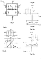
- Figures 1 and 2 illustrate parameters of a battery monitoring system with a closed-loop current sensor, where: N is the number of secondary turns I Fe is the average magnetic circuit length S Fe is the magnetic circuit cross section i is the excitation current I P is the primary current (to be measured), and ⁇ is the magnetic flux.
- the main difficulty in this type of application is the measurement of the current, because it can vary in a very large range, from the few milliamperes of the trickle charging (float) currents to the several hundreds of ampere of the battery discharge and recharge currents.
- the main parameters of the saturable inductor are defined in fig. 2 . While knowing the characteristics B ( H ) of the core, as well as the geometric parameters of the magnetic circuit, the inductance value can be defined as a function of the excitation current i .
- B ( H ) magnetic induction B as a function of the magnetic field H of the magnetic circuit
- B ( H ) is represented by the well known equation (1):
- B H ⁇ 0 ⁇ ⁇ r ⁇ H if - H s ⁇ H ⁇ + H s
- ⁇ 0 is the permeability coefficient of air
- ⁇ r is the relative permeability coefficient of the magnetic material of the circuit.
- Figure 4 illustrates an idealized characteristic ⁇ ( i ), the flux linkage, as a function of current.
- the geometric parameters of the magnetic circuit as well as the number of turns N allow to determine the relationship between the flux linkage ⁇ and the excitation current i .
- Figure 5 illustrates an idealized inductance value as a function of the excitation current.
- the inductance value L f is ⁇ r times higher than L e .
- the saturated value of the inductance L e is zero.
- H P the magnetic field strength created by the primary current.
- B H ⁇ 0 ⁇ ⁇ r ⁇ H - H P
- Figure 6 illustrates a shifting of the inductance value for a positive primary current (I P > 0).
- the positive saturation current is i 1
- the negative saturation current is i 2 .
- the characteristic L ( i ) is not symmetrical any more.
- Figure 7 illustrates a measuring circuit layout of an embodiment of a sensor according to this invention.
- the current to be measured is the primary current of a current transformer built with a suitable toroidal core.
- the H-bridge excites the secondary coil alternatively with a positive and a negative voltage.
- the coil resistance is R s .
- the excitation current is measured with the resistance R m .
- a measurement cycle may comprise four steps. At the beginning of the measuring sequence, the inductance is "unloaded", i.e. the current in the winding is zero, and all switches are open.
- Step 1) The MOSFETs "P" are switched on.
- the inductor 4 which represents an inductance L is charged with a positive current +i, according to the directions shown in fig. 7 . Once saturation is reached, the transistors are switched off.
- Step 2 The inductance discharges itself through the free-wheeling diodes of the "N" switches. Before passing to next step, the inductance is preferably completely discharged.
- Step 3 The MOSFETs "N" are switched on. This time a negative current in the inductance builds up. When saturation is reached, the switches are turned off.
- Step 4 The inductance discharge itself through the free-wheeling diodes of the "P" switches. Again the discharge of the inductance is preferably completed before the beginning of next sequence.
- the measured values of the times t 1 , t 2 to reach saturation and of the average excitation current i average during phases P resp. N are used to calculate the primary current. These operations may be performed by a microcontroller (not shown) to which the measuring circuit is connected, during the two charging periods, for example making use of an ADC unit and a timer of the microcontroller. When saturation is reached, the rapid increase of the excitation current i through the measuring resistance R m may be detected through a comparator. The saturation time t 1 , t 2 is calculated between the closing of the switches and the detection of saturation. The average value of the excitation current i average can then be calculated. For a zero primary current, a measuring sequence requires for example about 180 ms.
- the inductance characteristic L L ( i ) shifts toward the left. It can be demonstrated that this shift is proportional to the primary current I P . If the primary current ( I P / N ) is negative, the inductance characteristic shifts toward the right. In fig. 8 , t 1 is the saturation time for a positive current, t 2 is the saturation time for a negative current, i 1 is the positive saturation current and i 2 is the negative saturation current. This shift has a consequence on the time to saturation of the inductor ( fig.8 ).
- the primary current is a function of the times to saturation.
- V C The H-bridge supply voltage V C doesn't appear explicitly in this equation, so a precise stabilization of this voltage is not required.
- the excitation current attains the steady-state value of V C / R .
- the above measuring method for small primary currents can be used for primary currents respecting the following condition: I P N ⁇ i s ⁇ 0
- this condition means a measuring range (primary current) of ⁇ 7 A.
- a different measuring method is used.
- the fig. 11 shows the times to saturation for zero primary current.
- the P (respectively N) signal imposes the beginning of the positive (respectively negative) charging phase.
- the U m signal is the voltage on the measuring resistance R m .
- the diodes' free-wheeling current imposes a negative voltage U m .
- the threshold is reached immediately, and this allows to determine the flow direction of the primary current.
- Figure 13 illustrates a transducer current error (mA) for -1 A ⁇ I P ⁇ 1 A;
- Figure 13 illustrates a transducer current error (%) for -15 A ⁇ I P ⁇ 15 A;
- Figure 15 illustrates a transducer current error (%) for -1000 A ⁇ I P ⁇ 1000 A.
Landscapes
- Physics & Mathematics (AREA)
- General Physics & Mathematics (AREA)
- Engineering & Computer Science (AREA)
- Power Engineering (AREA)
- Condensed Matter Physics & Semiconductors (AREA)
- Measurement Of Current Or Voltage (AREA)
- Measuring Instrument Details And Bridges, And Automatic Balancing Devices (AREA)
Description
- The present invention relates to a closed-loop current sensor, in particular of the fluxgate type.
- A conventional fluxgate sensor typically comprises a core in a soft magnetic material of high magnetic permeability that is subjected to an alternating magnetic field by an excitation coil of the fluxgate. The magnetic field of the excitation coil saturates the core in an alternating manner. In the presence of a magnetic field, for example an external magnetic field generated by a current flowing in a primary conductor, the saturation characteristic of the soft magnetic core becomes (apparently, as seen from the secondary side) asymmetric and generates a corresponding signal in the circuit driving the fluxgate coil. The resulting signal is correlated to the amplitude of the external magnetic field. In a closed-loop sensor, this signal is used in a feedback loop to drive a secondary coil on a magnetic circuit configured to cancel the effect of the external magnetic field. The main advantage of closed-loop fluxgate sensors is their measurement sensitivity and ability to accurately measure currents of small amplitude. On the other hand, such sensors are generally not best suited for the measurement of currents of large amplitude, and like other sensors, have a limited measurement range.
- Fluxgate detectors for measuring magnetic fields are described for instance in
US3,626,280 ,US 6,166,539 , and in the publication Primdahl, Ripka,Petersen Nielsen from the Danish Space Research Institute, Meas Sci. Technol. (1991) 1039-1045. - Certain applications require however the measurement of a large range of currents. An example of an application requiring the accurate measurement of small amplitude currents and a large measurement range, is monitoring of batteries. Battery monitoring may include measuring different parameters of a battery system, temperature, voltage, impedance and current, in order to evaluate the status (charge, health) of the battery [2]. Often it is necessary to monitor complex systems made of several hundreds of blocks, e.g. at industrial UPS, telecommunications systems, or battery storage systems. One of the difficulties concerning battery monitoring applications is the current measurement, where the concerning battery monitoring applications is the current measurement, where the measurement range (DC) may typically vary from 10 mA up to 1000 A. Today's available low cost current transducers are not well adapted to work with sufficient accuracy for the small amplitude currents while supporting the very large measurement range, which may vary from a few milliamperes of trickle charging (float) currents to several hundreds of amperes of battery discharge and recharge currents.
- Certain electrical motors, generators and other electrical drives may also require the measurement of currents over a very large range for accurate and reliable control of the drive or generator.
- An object of the invention is to provide a current sensor that accurately measures small currents, yet has a large measurement range.
- It is advantageous to provide a current sensor that is economical to produce.
- It is advantageous to provide a current sensor for battery monitoring that is accurate and economical to produce.
- It is advantageous to provide a current sensor that is easy to implement.
- It is advantageous to provide a current sensor that is compact and reliable.
- Objects of the invention have been achieved by providing the closed-loop fluxgate sensor according to
claim 6 and a current measuring method according toclaim 1. - Disclosed herein is a fluxgate electrical current sensor comprising a measuring circuit and an inductor for measuring a primary current I P flowing in a primary conductor over a current range from a minimum measurable or specified current amplitude (Imin) to a maximum measurable or specified current amplitude (Imax), the inductor comprising a saturable magnetic core made of a highly permeable magnetic material and a secondary coil for applying an alternating excitation current i configured to alternatingly saturate the magnetic core, the coil being connected to the measuring circuit. The measuring circuit is configured to measure the saturation times t 1 and t 2 of the magnetic core in opposing magnetic field directions and determine therefrom a value of the primary current for small current amplitudes, the measuring circuit being further configured for evaluating the average value of the excitation current i and determining therefrom the value of the primary current for large currents.
- A method of measuring an electrical current flowing in a primary conductor over a current range from a minimum specified current amplitude to a maximum specified current amplitude according to this invention includes:
- providing a current sensor including a measuring circuit and an inductor, the inductor comprising a secondary coil wound around a saturable magnetic core,
- applying an excitation voltage to the secondary coil configured to alternatingly saturate the magnetic core,
- evaluating the average value of the excitation current flowing through the inductor during the phases when the voltage source is turned on for measurement of large primary currents, and
- measuring the times to saturation t 1, t 2 of the magnetic core of the negative respectively positive signal of the alternating excitation current and for small currents determining the primary current based on the relationship of alternating saturation times t 1, t 2.
- where small primary currents have amplitudes in a first portion of the current range from the minimum specified current Imin to a transition or intermediate amplitude, and large primary currents have an amplitude in a second portion of the current range from the transition amplitude to the maximum specified current amplitude Imax.
- Small primary currents have amplitude in a first portion of the current range from the minimum specified current Imin to a transition or intermediate amplitude, and large primary currents have an amplitude in a second portion of the current range from the transition amplitude to the maximum specified current amplitude Imax· The value of the intermediate amplitude, where the transition from the first measurement method to the second measurement method, may vary as a function of the values of Imin and Imax.
- The current sensor according to this invention, which is based on a technology of type "fluxgate", is economical to produce and implement yet has a wide measurement range while providing excellent accuracy. The sensor uses the magnetic field created by a primary current acting on a saturable inductor. By measuring the intervals to reach saturation and the inductor load current and making use of a suitable microcontroller it is possible to accurately evaluate the value of the primary current for both high and low current levels.
- For primary currents I P that are small, the primary current value may be determined based on a value of the saturation time in one direction divided by the sum of the saturation times in both directions (I P is proportional to t 1 / (t 1 + t 2)).
- The measuring method for small currents is preferably employed for primary currents respecting the following condition:

where I P is primary current, N the number of turns of the secondary coil, and i s0 the value of the saturation excitation current for a primary current that is 0. - For large primary currents the measurement of the primary current may be based on an evaluation of the average value of the excitation current.
- Further objects and advantageous features of the invention will be apparent from the claims and the following detailed description of embodiments of the invention and the annexed drawings in which:
-
Figure 1 is a simplified illustration of a battery monitoring system indicating the measured parameters; -
Figure 2 illustrates a saturable inductor of a current sensor according to an embodiment of this invention and its main parameters; -
Figure 3 is a graphical illustration of an idealized characteristic B(H) of the inductor; -
Figure 4 is a graphical illustration of an idealized characteristic of flux linkage ψ(i) as a function of current I flowing in a secondary coil of the inductor; -
Figure 6 is a graphical illustration of a shifting of the inductance value for a primary current (current to be measured) greater than zero (/p > 0); -
Figure 7 illustrates a circuit diagram of an embodiment of a measuring circuit of a current sensor according to this invention; -
Figures 8a and 8b are simplified graphs illustrating the shifting of the inductance value, respectively the saturation times t 1 and t 2 for a positive primary current (I P > 0); -
Figures 9a and 9b are graphical illustrations of the inductance as a function of current respectively the current as a function of time for a positive primary current to depict the relationship between the primary current and the excitation current; -
Figures 10a and 10b are similar tofigures 9a, 9b but for a negative primary current; -
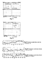
Figure 11 is a screen-shot of an oscilloscope illustrating saturation times for a positive excitation current signal P and a negative excitation current signal N for a primary current that is 0; -
Figure 12 is a screen-shot of an oscilloscope for a voltage U m at a primary current of 1000 Ampere; -
Figure 13 to 15 illustrate test results of a prototype current sensor made according to the invention wherefigure 13 illustrates measured current error in milliamperes for a primary current in the range of -1 to +1 amperes,figure 14 illustrates the sensor error in percentage for a primary current ranging from -15 to +15 amperes, andfigure 15 illustrates the sensor error in percentage for a primary current in the range of -1000 to +1000 amperes. - Referring to
figures 1, 2 and7 , an embodiment of a current sensor according to this invention, for measuring a primary current I P flowing in aprimary conductor 2, for example connected to abattery 1 or other electrical device or motor, the primary current corresponding to the charge or discharge current of the battery, or a drive current of an electrical motor. The sensor comprises an inductor 4 (representing an inductance L) connected to ameasuring circuit 6. The inductor comprises amagnetic circuit 8 comprising amagnetic core 10 made of a high magnetic permeability material (soft magnetic material), and a secondary coil (also called herein excitation coil) 12 wound around at least a portion of the saturablemagnetic core 10. Thesecondary coil 12 is connected to themeasuring circuit 6 which feeds an excitation current +i, -i through the secondary coil, the excitation current being configured to alternatingly saturate the magnetic core in one direction and then in the opposed direction. In the embodiment shown, the magnetic core is in the form of an annular closed ring having acentral passage 14 through which the primary conductor extends. - The primary conductor is shown as a single conductor passing straight through the central passage of the magnetic core, however it is also possible to have a primary conductor with one or more turns (windings) around a portion of the saturable core. The portion of primary conductor may be integrated to the current sensor and comprises connection terminals for connection to an external primary conductor of the system to be measured. The primary conductor may also be separate from the sensor and inserted through the sensor. The magnetic core may have other shapes than circular, for example rectangular, square, polygonal or other shapes. Moreover, the magnetic core of the inductor may also form a non-closed circuit, for example in the form of a bar or an almost closed magnetic core with an air gap. The magnetic core may also be formed of more than one part, for example of two halves or two parts that are assembled together around the primary conductor. Also, the current sensor may comprise a magnetic core that does not have a central passage through which the primary conductor extends whereby the primary conductor can be positioned in proximity of the magnetic core or wound around in one or more turns around a portion of the magnetic core. In these various configurations, the functioning principle remains essentially the same whereby the excitation in the secondary coil is an alternating current that saturates the magnetic core in alternating directions, and where the primary current generates a magnetic field that affects the saturation characteristic of the magnetic core.
- In the present invention, for small currents the measuring circuit measures the shift of the inductance characteristic as a function of the excitation current, this shift being essentially proportional to the amplitude of the primary current. For large primary currents however, this measuring principle is no longer employed because the core is already completely saturated without any secondary (excitation) current and the result of the relationship t1 / (t1 + t 2) does not change any more. For high currents the measuring circuit thus employs another measurement method, this method comprising evaluating the average value of the secondary coil excitation current during the time the excitation voltage is supplied, i.e. t 1 or t 2 which corresponds to the amplitude of the primary current as described in more detail hereafter.
- Advantageously, a single, simple and low cost sensor can thus be used for measuring a very large current range.
-
Figures 1 and 2 illustrate parameters of a battery monitoring system with a closed-loop current sensor, where:N is the number of secondary turns I Fe is the average magnetic circuit length S Fe is the magnetic circuit cross section i is the excitation current I P is the primary current (to be measured), and φ is the magnetic flux. - The main difficulty in this type of application is the measurement of the current, because it can vary in a very large range, from the few milliamperes of the trickle charging (float) currents to the several hundreds of ampere of the battery discharge and recharge currents.
- The main parameters of the saturable inductor are defined in
fig. 2 . While knowing the characteristics B(H) of the core, as well as the geometric parameters of the magnetic circuit, the inductance value can be defined as a function of the excitation current i. - The ideal characteristic B(H) (magnetic induction B as a function of the magnetic field H) of the magnetic circuit can be approximated as shown in
fig. 3 . For a magnetic field value varying between +H s and -H s the core is not saturated, so B(H) is represented by the well known equation (1):
where µ 0 is the permeability coefficient of air, and µ r is the relative permeability coefficient of the magnetic material of the circuit. -
Figure 4 illustrates an idealized characteristic ψ(i), the flux linkage, as a function of current. The geometric parameters of the magnetic circuit as well as the number of turns N allow to determine the relationship between the flux linkage ψ and the excitation current i.

- By replacing (2) in (1) we can obtain:

- And by replacing (4) in (3) we obtain:

and finally:
- By deriving (6) as a function of the current we obtain the inductance value as (7):

-
Figure 5 illustrates an idealized inductance value as a function of the excitation current. When the magnetic material is not saturated, this value can be obtained from
- Once saturation is reached, the inductance value is described by:
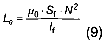
- The inductance value L f is µ r times higher than L e. For example, in the case of a test prototype, L f = 22 H while L e= 2 mH. In the following, we will make the hypothesis that the saturated value of the inductance L e is zero. Taking the current flow directions shown in
fig. 2 , the characteristic L(i) shifts to the left by applying a positive current to the primary and in case of negative primary current, the characteristic shifts to the right. This shifting is correlated to the primary current, and theoretically proportional to the primary current as demonstrated below. - Let us consider H P, the magnetic field strength created by the primary current. We can write:

- By replacing (2) into (10) we obtain:

- And replacing (11) into (3) we obtain:


- From (13) it can be seen that the amount of shifting of the flux characteristics is I P/N.
-
Figure 6 illustrates a shifting of the inductance value for a positive primary current (IP > 0). The current i s0 is the value of the saturation excitation current for I P = 0. In this case the characteristic L(i) is symmetrical and +i s0 = -i s0. For a non-zero primary current I P the positive saturation current is i 1, while the negative saturation current is i 2. In this case the characteristic L(i) is not symmetrical any more. With a positive primary current: i 1 < |i 2| , the characteristic's parameters can be calculated as:

- As an example, in a prototype tested with +i s0 = 7 mA and N = 1000, a primary current of 1 A caused a positive saturation limit of i 1 = (0.007-1/1000) A = 6 mA.
-
Figure 7 illustrates a measuring circuit layout of an embodiment of a sensor according to this invention. The current to be measured is the primary current of a current transformer built with a suitable toroidal core. The secondary (measuring) circuit is made of a DC voltage source V C = 12 V, supplying an H-bridge circuit design made of MOSFETs. The H-bridge excites the secondary coil alternatively with a positive and a negative voltage. The coil resistance is R s. The excitation current is measured with the resistance R m. A measurement cycle may comprise four steps. At the beginning of the measuring sequence, the inductance is "unloaded", i.e. the current in the winding is zero, and all switches are open. - Step 1) The MOSFETs "P" are switched on. The
inductor 4 which represents an inductance L is charged with a positive current +i, according to the directions shown infig. 7 . Once saturation is reached, the transistors are switched off. - Step 2) The inductance discharges itself through the free-wheeling diodes of the "N" switches. Before passing to next step, the inductance is preferably completely discharged.
- Step 3) The MOSFETs "N" are switched on. This time a negative current in the inductance builds up. When saturation is reached, the switches are turned off.
- Step 4) The inductance discharge itself through the free-wheeling diodes of the "P" switches. Again the discharge of the inductance is preferably completed before the beginning of next sequence.
- The measured values of the times t 1, t 2 to reach saturation and of the average excitation current i average during phases P resp. N are used to calculate the primary current. These operations may be performed by a microcontroller (not shown) to which the measuring circuit is connected, during the two charging periods, for example making use of an ADC unit and a timer of the microcontroller. When saturation is reached, the rapid increase of the excitation current i through the measuring resistance R m may be detected through a comparator. The saturation time t 1, t 2 is calculated between the closing of the switches and the detection of saturation. The average value of the excitation current i average can then be calculated. For a zero primary current, a measuring sequence requires for example about 180 ms.
- By applying a positive primary current, taking the current flow directions shown in
fig. 2 , the inductance characteristic L=L(i) shifts toward the left. It can be demonstrated that this shift is proportional to the primary current I P. If the primary current (I P/N) is negative, the inductance characteristic shifts toward the right. Infig. 8 , t 1 is the saturation time for a positive current, t 2 is the saturation time for a negative current, i 1 is the positive saturation current and i 2 is the negative saturation current. This shift has a consequence on the time to saturation of the inductor (fig.8 ). - In order to calculate the time domain behavior of this circuit, the resistive part of the circuit (R = R s+R m) can be neglected. Indeed the saturation times are small (typically 20 ms) in comparison with the time constant (L f = 22 H and R = 5 Ω). Then, after applying the voltage step we obtain the linear relationship:

- The excitation current is linearly and directly related to the primary current. Once saturation is reached, the current increases instantaneously (L e = 0) up to its steady-state value:

- The primary current is a function of the times to saturation. In
fig. 8 the behaviour for a positive primary current is shown.Figure 8 illustrates saturation times t 1 and t 2 for a positive primary current
- By replacing (15) and (16) into (19) we obtain

and by replacing (14) into (20) we obtain
- The H-bridge supply voltage V C doesn't appear explicitly in this equation, so a precise stabilization of this voltage is not required. Once saturation is reached, the excitation current attains the steady-state value of V C/R. As an example, in a test prototype, this value was V C/R = 2.4 A, however, the MOSFETs were switched off at about 1.25 A (i threshold) because the application didn't require a higher current value.
- The above measuring method for small primary currents can be used for primary currents respecting the following condition:

- As an example, in a test prototype this condition means a measuring range (primary current) of ±7 A. For higher primary current values, a different measuring method is used.
- If |I P/N| > i s0, the characteristics L(i) translate far to the left. This means that the inductance is already saturated without any excitation current flowing. With a large negative primary current, the phenomenon is the same but reversed (shift to the right).
Figure 9 illustrates relationships between I P and i average. The relationships established for the measurement of small primary currents discussed above can no longer be used. In this case, the measurement is made by evaluating the average value of the excitation current during the phases "P" or "N". The average value i average of the characteristics illustrated infig. 9 , which corresponds to the inductor current when themagnetic core 10 is not saturated, represents I P/N. In order to obtain the primary current, we can calculate the average value of the excitation current (value between i n and i n') and multiply it by the number of turns.
- An exemplary embodiment has the following characteristics
- Measuring range : 0..±1000 A DC
- Error @Ta = 25°C : ±10 mA for I P = 0 to ±1A
: ±1 % for I P = 1±1000 A - Supply voltage : 12 V
- Supply current : 250 mA (average)
- Settling time : ≤1 s
- Ouput type : digital
- The
fig. 11 shows the times to saturation for zero primary current. The P (respectively N) signal imposes the beginning of the positive (respectively negative) charging phase. The U m signal is the voltage on the measuring resistance R m. - From (17) in our case we can find: for I P = 0:

- After this time, due to the saturation of the inductor, the voltage U m reaches the opening voltage of the switches

- After that, the diodes' free-wheeling current imposes a negative voltage U m.
-
Figure 11 illustrates saturation times for I P=0. -
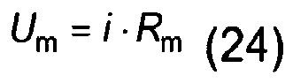
Figure 12 shows the measuring voltage with a primary current of +1000 A and illustrates Voltage U m at I P = +1000 A. For the positive excitation current, the threshold is reached immediately, and this allows to determine the flow direction of the primary current. For a negative excitation current, relation (23) allows the calculation of its average value:
- According to (24), the voltage U m is

- Each measuring cycle, the transducer's digital output transmits the value of the primary current.
Fig. 13, 14 and 15 represent the error of the transducer current as a function of the primary current (Ta=25 °C) for the tested prototype discussed above.Figure 13 illustrates a transducer current error (mA) for
-1 A ≤ I P ≤ 1 A;
Figure 13 illustrates a transducer current error (%) for
-15 A ≤ I P ≤ 15 A; and
Figure 15 illustrates a transducer current error (%) for
-1000 A ≤ I P ≤ 1000 A. -
- [1] W. Teppan, "Transfer Functions of Current Sensors", 5th Int. IMEKO, TC-4 Symposium on Electrical Measuring Instruments for Low and Medium Frequencies, Vienna, Austria, 8-10 April 1992
- [2] Waltari, T. Suntio: "Survey and evaluation of battery monitoring methods and results from user's viewpoint", 21 st International Telecommunications Energy Conference, 1999. INTELEC'99, 6-9 June 1999 Page(s):7 pp.
Claims (14)
- Electrical current sensor comprising a measuring circuit (6) and an inductor (4) for measuring a primary current I P flowing in a primary conductor (2) over a current range from a minimum specified current amplitude to a maximum specified current amplitude, the inductor comprising a saturable magnetic core (10) made of a highly permeable magnetic material and a secondary coil (12) for carrying an alternating excitation i configured to alternatingly saturate the magnetic core, the coil being connected to the measuring circuit, wherein the measuring circuit is configured to supply a positive or negative voltage to the inductor, to switch off the voltage when a condition signalling saturation is reached, to measure the time to saturation t 1 in one direction and the time to saturation t 2 in the other direction of the magnetic core and determine therefrom a value of the primary current for primary currents having an amplitude in a first portion of the current range from the minimum specified current to a transition amplitude, the measuring circuit being further configured for evaluating the average value of the excitation current i during the phases when a voltage is supplied to the inductor and before the saturation condition is reached, and determining therefrom the value of the primary current for primary currents having an amplitude in a second portion of the current range from the transition amplitude to the maximum specified current amplitude.
- Electrical current sensor according to claim 1 wherein the measuring circuit includes a DC voltage source V C , and an H-bridge circuit supplied by the DC voltage source configured to excite the secondary coil alternatively with a positive and a negative voltage.
- Electrical current sensor according to claim 2 wherein switches of the H-Bridge comprise MOSFETs.
- Electrical current sensor according to claim 1, 2 or 3 wherein the measuring circuit comprises a resistance R m to measure the excitation current.
- Electrical current sensor according to any one of the preceding claims wherein the saturable magnetic core is annular and closed.
- Electrical current sensor according to any one of the preceding claims further including a microcontroller to which the measuring circuit is connected, the microcontroller comprising a timer for measuring the saturation times t 1, t 2.
- A method of measuring an electrical current flowing in a primary conductor over a current range from a minimum specified current amplitude to a maximum specified current amplitude comprising:- providing a current sensor including a measuring circuit and an inductor, the inductor comprising a secondary coil wound around a saturable magnetic core,- applying an excitation voltage to the secondary coil to alternatingly saturate the magnetic core,- evaluating the average value of the excitation current during the phases the excitation voltage is applied for measurement of large primary currents, and- measuring the times to saturation t 1, t 2 of the magnetic core of the negative respectively positive signal of the alternating excitation current and for small currents determining the primary current based on the relationship of alternating saturation times t 1, t 2,where small primary currents have amplitudes in a first portion of the current range from the minimum specified current Imin to a transition or intermediate amplitude, and large primary currents have an amplitude in a second portion of the current range from the transition amplitude to the maximum specified current amplitude Imax.
- Method according to the preceding claim, wherein for primary currents I P that are small, the primary current is based on a value of the saturation time in one direction divided by the sum of the saturation times in both directions.
- Measuring method according to claim 7 or 8, wherein the measuring method for small currents is employed for primary currents respecting the following condition:

where I P is primary current, N the number of turns of the secondary coil, and i s0 the value of the saturation excitation current for a primary current that is 0. - Method according to anyone of the preceding claims 7 to 9, wherein for large primary currents the measurement of the primary current is based on an evaluation of the average value of the excitation current during the phases when an excitation voltage is supplied.
- Method according to anyone of the preceding claims 7 to 10, wherein the measuring circuit includes a DC voltage source V C , and an H-bridge circuit with transistor switches supplied by the DC voltage source configured to excite the secondary coil alternatively with a positive (P) and a negative (N) voltage, comprising the steps of:- switching on the transistors configured to supply a positive voltage to the excitation coil thus charging the inductor (4) with a positive current +i until saturation of the magnetic core is reached, switching off the transistors;- measuring the time t 1 to reach saturation;- discharging the inductance;- switching on the transistors configured to supply a negative voltage to the excitation coil thus charging the inductor (4) with a negative current -i, and once saturation of the magnetic core is reached, switching off the transistors;- measuring the time t 2 to reach saturation;- discharging the inductance.
- Method according to the preceding claim wherein saturation of the magnetic core is detected through a comparator by determining reaching a certain threshold of the excitation current i through a measuring resistance R m.
- Method according to the preceding claim wherein the saturation times t 1 , t 2 are determined between the closing of the switches and the detection of saturation.
- Method according to the preceding claim wherein the value of the saturation times are calculated by a microcontroller to which the measuring circuit is connected, making use of a timer unit of the microcontroller.
Priority Applications (1)
| Application Number | Priority Date | Filing Date | Title |
|---|---|---|---|
| EP10726246.1A EP2430469B1 (en) | 2009-05-11 | 2010-05-10 | Closed-loop fluxgate current sensor |
Applications Claiming Priority (3)
| Application Number | Priority Date | Filing Date | Title |
|---|---|---|---|
| EP09159946A EP2251704A1 (en) | 2009-05-11 | 2009-05-11 | Closed-loop fluxgate current sensor |
| EP10726246.1A EP2430469B1 (en) | 2009-05-11 | 2010-05-10 | Closed-loop fluxgate current sensor |
| PCT/IB2010/052059 WO2010131187A1 (en) | 2009-05-11 | 2010-05-10 | Closed-loop fluxgate current sensor |
Publications (2)
| Publication Number | Publication Date |
|---|---|
| EP2430469A1 EP2430469A1 (en) | 2012-03-21 |
| EP2430469B1 true EP2430469B1 (en) | 2013-05-08 |
Family
ID=41110796
Family Applications (2)
| Application Number | Title | Priority Date | Filing Date |
|---|---|---|---|
| EP09159946A Withdrawn EP2251704A1 (en) | 2009-05-11 | 2009-05-11 | Closed-loop fluxgate current sensor |
| EP10726246.1A Not-in-force EP2430469B1 (en) | 2009-05-11 | 2010-05-10 | Closed-loop fluxgate current sensor |
Family Applications Before (1)
| Application Number | Title | Priority Date | Filing Date |
|---|---|---|---|
| EP09159946A Withdrawn EP2251704A1 (en) | 2009-05-11 | 2009-05-11 | Closed-loop fluxgate current sensor |
Country Status (5)
| Country | Link |
|---|---|
| US (1) | US8797020B2 (en) |
| EP (2) | EP2251704A1 (en) |
| JP (1) | JP5606521B2 (en) |
| CN (1) | CN102422174B (en) |
| WO (1) | WO2010131187A1 (en) |
Families Citing this family (17)
| Publication number | Priority date | Publication date | Assignee | Title |
|---|---|---|---|---|
| EP2284549A1 (en) * | 2009-08-11 | 2011-02-16 | Liaisons Electroniques-Mècaniques LEM S.A. | Mixed mode fluxgate current transducer |
| WO2013027074A2 (en) * | 2011-08-23 | 2013-02-28 | ARACONSYS Kft. | Magnetometer, method for its operation and non-destructive material testing apparatus |
| DE102012216553A1 (en) | 2012-09-17 | 2014-03-20 | Siemens Aktiengesellschaft | Method for current measurement in primary conductor for e.g. long overhead lines for distributing electrical energy, involves adjusting compensation current based on regulating signal, and determining current based on adjusted current |
| CN103852619A (en) * | 2012-12-05 | 2014-06-11 | 北京柏艾斯科技有限公司 | Open type current sensor based on closed loop fluxgate technology |
| CN104122430A (en) * | 2013-04-26 | 2014-10-29 | 深圳奥特迅电力设备股份有限公司 | Non-contact minimal direct current detection apparatus |
| DE102013210800A1 (en) * | 2013-06-10 | 2014-12-11 | Bender Gmbh & Co. Kg | Integrated circuit with digital method for AC-sensitive differential current measurement |
| US9291648B2 (en) * | 2013-08-07 | 2016-03-22 | Texas Instruments Incorporated | Hybrid closed-loop/open-loop magnetic current sensor |
| CN104090146B (en) * | 2014-07-24 | 2017-01-18 | 中国科学院上海应用物理研究所 | Alternating current/direct current sensor |
| CN106018920B (en) * | 2016-05-25 | 2018-09-18 | 河北工业大学 | A kind of single magnetic core complicated wave form current sensor |
| JP6551448B2 (en) * | 2017-03-30 | 2019-07-31 | Tdk株式会社 | Current sensor |
| JP2018169303A (en) * | 2017-03-30 | 2018-11-01 | Tdk株式会社 | Current sensor |
| CN107102187B (en) * | 2017-05-09 | 2020-09-25 | 中国电力科学研究院 | Zero-flux fluxgate current sensor for measuring alternating current and direct current heavy current |
| WO2019110687A1 (en) * | 2017-12-08 | 2019-06-13 | Lem Intellectual Property Sa | Toroidal fluxgate current transducer |
| DE102018204129B3 (en) * | 2018-03-19 | 2019-07-04 | Siemens Aktiengesellschaft | Method and device for measuring an alternating current with a Rogowski current transformer |
| US10895611B1 (en) * | 2018-03-23 | 2021-01-19 | Orbital Research Inc. | Self-calibrating fluxgate magnetometer and methods of using |
| CN109870663B (en) * | 2019-03-11 | 2021-02-26 | 深圳市信瑞达电力设备有限公司 | Driving method of magnetic circuit, magnetic measuring device and current detecting device |
| TWI912828B (en) * | 2024-07-11 | 2026-01-21 | 台達電子工業股份有限公司 | Closed-loop current sensor and operation method thereof |
Family Cites Families (17)
| Publication number | Priority date | Publication date | Assignee | Title |
|---|---|---|---|---|
| US3626280A (en) * | 1970-04-03 | 1971-12-07 | Collins Radio Co | Frequency controlled flux detector excitation |
| JPH0619378B2 (en) * | 1983-04-01 | 1994-03-16 | ティーディーケイ株式会社 | Current detector |
| DE68924112T2 (en) * | 1988-08-24 | 1996-04-18 | Lem Liaisons Electron Mec | Current sensor. |
| CH679527A5 (en) * | 1989-04-13 | 1992-02-28 | Lem Liaisons Electron Mec | |
| JP2816175B2 (en) * | 1989-04-28 | 1998-10-27 | 三菱電機株式会社 | DC current measuring device |
| JP2586156B2 (en) * | 1989-06-23 | 1997-02-26 | 富士電機株式会社 | AC / DC dual-purpose current detection method |
| US5229725A (en) * | 1992-04-07 | 1993-07-20 | Moore Products Co. | Electrical fault detector in remote systems using a saturable core |
| US6166539A (en) * | 1996-10-30 | 2000-12-26 | Regents Of The University Of Minnesota | Magnetoresistance sensor having minimal hysteresis problems |
| CH692161A5 (en) * | 1997-07-04 | 2002-02-28 | Lem Liaisons Electron Mec | current sensor. |
| US6160697A (en) * | 1999-02-25 | 2000-12-12 | Edel; Thomas G. | Method and apparatus for magnetizing and demagnetizing current transformers and magnetic bodies |
| US6522517B1 (en) * | 1999-02-25 | 2003-02-18 | Thomas G. Edel | Method and apparatus for controlling the magnetization of current transformers and other magnetic bodies |
| EP1498739B1 (en) * | 2003-07-12 | 2006-04-05 | Liaisons Electroniques-Mecaniques Lem S.A. | Current sensor having a magnetic core with airgap and power supply circuit provided with such sensors |
| DE10331883B4 (en) * | 2003-07-14 | 2018-01-18 | Vacuumschmelze Gmbh & Co. Kg | Measuring method and measuring arrangement for measuring currents with a large dynamic range |
| ATE412188T1 (en) * | 2004-07-16 | 2008-11-15 | Lem Liaisons Electron Mec | CURRENT SENSOR |
| JP4676809B2 (en) * | 2005-04-22 | 2011-04-27 | 明星電気株式会社 | Magnetometer for biomagnetic measuring device |
| JP2007033222A (en) * | 2005-07-27 | 2007-02-08 | Tdk Corp | Current sensor |
| EP2284549A1 (en) * | 2009-08-11 | 2011-02-16 | Liaisons Electroniques-Mècaniques LEM S.A. | Mixed mode fluxgate current transducer |
-
2009
- 2009-05-11 EP EP09159946A patent/EP2251704A1/en not_active Withdrawn
-
2010
- 2010-05-10 JP JP2012510416A patent/JP5606521B2/en not_active Expired - Fee Related
- 2010-05-10 WO PCT/IB2010/052059 patent/WO2010131187A1/en not_active Ceased
- 2010-05-10 US US13/319,916 patent/US8797020B2/en active Active
- 2010-05-10 EP EP10726246.1A patent/EP2430469B1/en not_active Not-in-force
- 2010-05-10 CN CN201080020584.9A patent/CN102422174B/en active Active
Also Published As
| Publication number | Publication date |
|---|---|
| CN102422174A (en) | 2012-04-18 |
| US8797020B2 (en) | 2014-08-05 |
| US20120062209A1 (en) | 2012-03-15 |
| JP5606521B2 (en) | 2014-10-15 |
| WO2010131187A1 (en) | 2010-11-18 |
| CN102422174B (en) | 2014-06-18 |
| EP2251704A1 (en) | 2010-11-17 |
| EP2430469A1 (en) | 2012-03-21 |
| JP2012526981A (en) | 2012-11-01 |
Similar Documents
| Publication | Publication Date | Title |
|---|---|---|
| US8797020B2 (en) | Closed-loop fluxgate current sensor | |
| US9217763B2 (en) | Mixed mode fluxgate current transducer | |
| TWI432747B (en) | Apparatus for diagnosing deterioration of insulation | |
| KR100993928B1 (en) | Magnetic bridge type current sensor, magnetic bridge type current detection method, and magnetic bridge used in the sensor and detection method | |
| EP2821800B1 (en) | Current detection device | |
| JP5625525B2 (en) | Current detector | |
| JP6200445B2 (en) | Current detector | |
| JP2012526981A5 (en) | ||
| JP2011164027A (en) | Current sensor and battery with current sensor | |
| CN114585930B (en) | Flux gate current transformer | |
| CN104237618B (en) | Integrated circuit using digital method for AC/DC sensitive residual current measurement | |
| US20150293153A1 (en) | Fluxgate current sensor | |
| EP3105602B1 (en) | Sensor and method for electric current measurement | |
| JP5702592B2 (en) | Current detector | |
| JP2003315374A (en) | DC leakage detector | |
| CN114966159B (en) | Current sensor for contactless current measurement | |
| CN113514689A (en) | Device and method for measuring electrically insulated, AC/DC sensitive differential current | |
| JP2022123748A (en) | Current detection device | |
| JP2002022774A (en) | Magnetic-field-controlled balancing current sensor | |
| JP2013213725A (en) | Current detection device | |
| JP2012063218A (en) | Current detection device | |
| JPH10111118A (en) | Method and device for measuring distance, method and device for measuring elongation of endless moving object and the endless moving object | |
| CN119689353B (en) | A method for measuring residual magnetism of transformer based on magnetomotive force | |
| WO2006129389A1 (en) | Wide-band current detector | |
| JP2000055940A (en) | Dc current sensor |
Legal Events
| Date | Code | Title | Description |
|---|---|---|---|
| PUAI | Public reference made under article 153(3) epc to a published international application that has entered the european phase |
Free format text: ORIGINAL CODE: 0009012 |
|
| 17P | Request for examination filed |
Effective date: 20111202 |
|
| AK | Designated contracting states |
Kind code of ref document: A1 Designated state(s): AL AT BE BG CH CY CZ DE DK EE ES FI FR GB GR HR HU IE IS IT LI LT LU LV MC MK MT NL NO PL PT RO SE SI SK SM TR |
|
| DAX | Request for extension of the european patent (deleted) | ||
| RAP1 | Party data changed (applicant data changed or rights of an application transferred) |
Owner name: LEM INTELLECTUAL PROPERTY SA |
|
| GRAP | Despatch of communication of intention to grant a patent |
Free format text: ORIGINAL CODE: EPIDOSNIGR1 |
|
| GRAS | Grant fee paid |
Free format text: ORIGINAL CODE: EPIDOSNIGR3 |
|
| GRAA | (expected) grant |
Free format text: ORIGINAL CODE: 0009210 |
|
| AK | Designated contracting states |
Kind code of ref document: B1 Designated state(s): AL AT BE BG CH CY CZ DE DK EE ES FI FR GB GR HR HU IE IS IT LI LT LU LV MC MK MT NL NO PL PT RO SE SI SK SM TR |
|
| REG | Reference to a national code |
Ref country code: GB Ref legal event code: FG4D |
|
| REG | Reference to a national code |
Ref country code: AT Ref legal event code: REF Ref document number: 611324 Country of ref document: AT Kind code of ref document: T Effective date: 20130515 Ref country code: CH Ref legal event code: EP |
|
| REG | Reference to a national code |
Ref country code: CH Ref legal event code: NV Representative=s name: REUTELER AND CIE S.A., CH |
|
| REG | Reference to a national code |
Ref country code: IE Ref legal event code: FG4D |
|
| REG | Reference to a national code |
Ref country code: DE Ref legal event code: R096 Ref document number: 602010006969 Country of ref document: DE Effective date: 20130704 |
|
| REG | Reference to a national code |
Ref country code: AT Ref legal event code: MK05 Ref document number: 611324 Country of ref document: AT Kind code of ref document: T Effective date: 20130508 |
|
| REG | Reference to a national code |
Ref country code: LT Ref legal event code: MG4D |
|
| REG | Reference to a national code |
Ref country code: NL Ref legal event code: VDEP Effective date: 20130508 |
|
| PG25 | Lapsed in a contracting state [announced via postgrant information from national office to epo] |
Ref country code: SE Free format text: LAPSE BECAUSE OF FAILURE TO SUBMIT A TRANSLATION OF THE DESCRIPTION OR TO PAY THE FEE WITHIN THE PRESCRIBED TIME-LIMIT Effective date: 20130508 Ref country code: ES Free format text: LAPSE BECAUSE OF FAILURE TO SUBMIT A TRANSLATION OF THE DESCRIPTION OR TO PAY THE FEE WITHIN THE PRESCRIBED TIME-LIMIT Effective date: 20130819 Ref country code: IS Free format text: LAPSE BECAUSE OF FAILURE TO SUBMIT A TRANSLATION OF THE DESCRIPTION OR TO PAY THE FEE WITHIN THE PRESCRIBED TIME-LIMIT Effective date: 20130908 Ref country code: NO Free format text: LAPSE BECAUSE OF FAILURE TO SUBMIT A TRANSLATION OF THE DESCRIPTION OR TO PAY THE FEE WITHIN THE PRESCRIBED TIME-LIMIT Effective date: 20130808 Ref country code: LT Free format text: LAPSE BECAUSE OF FAILURE TO SUBMIT A TRANSLATION OF THE DESCRIPTION OR TO PAY THE FEE WITHIN THE PRESCRIBED TIME-LIMIT Effective date: 20130508 Ref country code: FI Free format text: LAPSE BECAUSE OF FAILURE TO SUBMIT A TRANSLATION OF THE DESCRIPTION OR TO PAY THE FEE WITHIN THE PRESCRIBED TIME-LIMIT Effective date: 20130508 Ref country code: PT Free format text: LAPSE BECAUSE OF FAILURE TO SUBMIT A TRANSLATION OF THE DESCRIPTION OR TO PAY THE FEE WITHIN THE PRESCRIBED TIME-LIMIT Effective date: 20130909 Ref country code: GR Free format text: LAPSE BECAUSE OF FAILURE TO SUBMIT A TRANSLATION OF THE DESCRIPTION OR TO PAY THE FEE WITHIN THE PRESCRIBED TIME-LIMIT Effective date: 20130809 Ref country code: SI Free format text: LAPSE BECAUSE OF FAILURE TO SUBMIT A TRANSLATION OF THE DESCRIPTION OR TO PAY THE FEE WITHIN THE PRESCRIBED TIME-LIMIT Effective date: 20130508 Ref country code: AT Free format text: LAPSE BECAUSE OF FAILURE TO SUBMIT A TRANSLATION OF THE DESCRIPTION OR TO PAY THE FEE WITHIN THE PRESCRIBED TIME-LIMIT Effective date: 20130508 |
|
| PG25 | Lapsed in a contracting state [announced via postgrant information from national office to epo] |
Ref country code: PL Free format text: LAPSE BECAUSE OF FAILURE TO SUBMIT A TRANSLATION OF THE DESCRIPTION OR TO PAY THE FEE WITHIN THE PRESCRIBED TIME-LIMIT Effective date: 20130508 Ref country code: HR Free format text: LAPSE BECAUSE OF FAILURE TO SUBMIT A TRANSLATION OF THE DESCRIPTION OR TO PAY THE FEE WITHIN THE PRESCRIBED TIME-LIMIT Effective date: 20130508 Ref country code: BG Free format text: LAPSE BECAUSE OF FAILURE TO SUBMIT A TRANSLATION OF THE DESCRIPTION OR TO PAY THE FEE WITHIN THE PRESCRIBED TIME-LIMIT Effective date: 20130808 Ref country code: CY Free format text: LAPSE BECAUSE OF FAILURE TO SUBMIT A TRANSLATION OF THE DESCRIPTION OR TO PAY THE FEE WITHIN THE PRESCRIBED TIME-LIMIT Effective date: 20130508 |
|
| PG25 | Lapsed in a contracting state [announced via postgrant information from national office to epo] |
Ref country code: LV Free format text: LAPSE BECAUSE OF FAILURE TO SUBMIT A TRANSLATION OF THE DESCRIPTION OR TO PAY THE FEE WITHIN THE PRESCRIBED TIME-LIMIT Effective date: 20130508 |
|
| PG25 | Lapsed in a contracting state [announced via postgrant information from national office to epo] |
Ref country code: CZ Free format text: LAPSE BECAUSE OF FAILURE TO SUBMIT A TRANSLATION OF THE DESCRIPTION OR TO PAY THE FEE WITHIN THE PRESCRIBED TIME-LIMIT Effective date: 20130508 Ref country code: DK Free format text: LAPSE BECAUSE OF FAILURE TO SUBMIT A TRANSLATION OF THE DESCRIPTION OR TO PAY THE FEE WITHIN THE PRESCRIBED TIME-LIMIT Effective date: 20130508 Ref country code: SK Free format text: LAPSE BECAUSE OF FAILURE TO SUBMIT A TRANSLATION OF THE DESCRIPTION OR TO PAY THE FEE WITHIN THE PRESCRIBED TIME-LIMIT Effective date: 20130508 Ref country code: BE Free format text: LAPSE BECAUSE OF FAILURE TO SUBMIT A TRANSLATION OF THE DESCRIPTION OR TO PAY THE FEE WITHIN THE PRESCRIBED TIME-LIMIT Effective date: 20130508 Ref country code: EE Free format text: LAPSE BECAUSE OF FAILURE TO SUBMIT A TRANSLATION OF THE DESCRIPTION OR TO PAY THE FEE WITHIN THE PRESCRIBED TIME-LIMIT Effective date: 20130508 |
|
| PLBI | Opposition filed |
Free format text: ORIGINAL CODE: 0009260 |
|
| REG | Reference to a national code |
Ref country code: IE Ref legal event code: MM4A |
|
| PG25 | Lapsed in a contracting state [announced via postgrant information from national office to epo] |
Ref country code: MC Free format text: LAPSE BECAUSE OF FAILURE TO SUBMIT A TRANSLATION OF THE DESCRIPTION OR TO PAY THE FEE WITHIN THE PRESCRIBED TIME-LIMIT Effective date: 20130508 Ref country code: IT Free format text: LAPSE BECAUSE OF FAILURE TO SUBMIT A TRANSLATION OF THE DESCRIPTION OR TO PAY THE FEE WITHIN THE PRESCRIBED TIME-LIMIT Effective date: 20130508 Ref country code: NL Free format text: LAPSE BECAUSE OF FAILURE TO SUBMIT A TRANSLATION OF THE DESCRIPTION OR TO PAY THE FEE WITHIN THE PRESCRIBED TIME-LIMIT Effective date: 20130508 Ref country code: RO Free format text: LAPSE BECAUSE OF FAILURE TO SUBMIT A TRANSLATION OF THE DESCRIPTION OR TO PAY THE FEE WITHIN THE PRESCRIBED TIME-LIMIT Effective date: 20130508 |
|
| PLAX | Notice of opposition and request to file observation + time limit sent |
Free format text: ORIGINAL CODE: EPIDOSNOBS2 |
|
| 26 | Opposition filed |
Opponent name: VACUUMSCHMELZE GMBH & CO. KG Effective date: 20140204 |
|
| REG | Reference to a national code |
Ref country code: FR Ref legal event code: ST Effective date: 20140303 |
|
| REG | Reference to a national code |
Ref country code: DE Ref legal event code: R026 Ref document number: 602010006969 Country of ref document: DE Effective date: 20140204 |
|
| PG25 | Lapsed in a contracting state [announced via postgrant information from national office to epo] |
Ref country code: IE Free format text: LAPSE BECAUSE OF NON-PAYMENT OF DUE FEES Effective date: 20130510 |
|
| PG25 | Lapsed in a contracting state [announced via postgrant information from national office to epo] |
Ref country code: FR Free format text: LAPSE BECAUSE OF NON-PAYMENT OF DUE FEES Effective date: 20130708 |
|
| PLBB | Reply of patent proprietor to notice(s) of opposition received |
Free format text: ORIGINAL CODE: EPIDOSNOBS3 |
|
| REG | Reference to a national code |
Ref country code: CH Ref legal event code: PL |
|
| GBPC | Gb: european patent ceased through non-payment of renewal fee |
Effective date: 20140510 |
|
| PG25 | Lapsed in a contracting state [announced via postgrant information from national office to epo] |
Ref country code: LI Free format text: LAPSE BECAUSE OF NON-PAYMENT OF DUE FEES Effective date: 20140531 Ref country code: CH Free format text: LAPSE BECAUSE OF NON-PAYMENT OF DUE FEES Effective date: 20140531 |
|
| PG25 | Lapsed in a contracting state [announced via postgrant information from national office to epo] |
Ref country code: MT Free format text: LAPSE BECAUSE OF FAILURE TO SUBMIT A TRANSLATION OF THE DESCRIPTION OR TO PAY THE FEE WITHIN THE PRESCRIBED TIME-LIMIT Effective date: 20130508 |
|
| PG25 | Lapsed in a contracting state [announced via postgrant information from national office to epo] |
Ref country code: SM Free format text: LAPSE BECAUSE OF FAILURE TO SUBMIT A TRANSLATION OF THE DESCRIPTION OR TO PAY THE FEE WITHIN THE PRESCRIBED TIME-LIMIT Effective date: 20130508 Ref country code: GB Free format text: LAPSE BECAUSE OF NON-PAYMENT OF DUE FEES Effective date: 20140510 |
|
| PG25 | Lapsed in a contracting state [announced via postgrant information from national office to epo] |
Ref country code: TR Free format text: LAPSE BECAUSE OF FAILURE TO SUBMIT A TRANSLATION OF THE DESCRIPTION OR TO PAY THE FEE WITHIN THE PRESCRIBED TIME-LIMIT Effective date: 20130508 |
|
| PG25 | Lapsed in a contracting state [announced via postgrant information from national office to epo] |
Ref country code: LU Free format text: LAPSE BECAUSE OF NON-PAYMENT OF DUE FEES Effective date: 20130510 Ref country code: HU Free format text: LAPSE BECAUSE OF FAILURE TO SUBMIT A TRANSLATION OF THE DESCRIPTION OR TO PAY THE FEE WITHIN THE PRESCRIBED TIME-LIMIT; INVALID AB INITIO Effective date: 20100510 Ref country code: MK Free format text: LAPSE BECAUSE OF FAILURE TO SUBMIT A TRANSLATION OF THE DESCRIPTION OR TO PAY THE FEE WITHIN THE PRESCRIBED TIME-LIMIT Effective date: 20130508 |
|
| PG25 | Lapsed in a contracting state [announced via postgrant information from national office to epo] |
Ref country code: AL Free format text: LAPSE BECAUSE OF FAILURE TO SUBMIT A TRANSLATION OF THE DESCRIPTION OR TO PAY THE FEE WITHIN THE PRESCRIBED TIME-LIMIT Effective date: 20130508 |
|
| PLCK | Communication despatched that opposition was rejected |
Free format text: ORIGINAL CODE: EPIDOSNREJ1 |
|
| STAA | Information on the status of an ep patent application or granted ep patent |
Free format text: STATUS: THE PATENT HAS BEEN GRANTED |
|
| APBM | Appeal reference recorded |
Free format text: ORIGINAL CODE: EPIDOSNREFNO |
|
| APBP | Date of receipt of notice of appeal recorded |
Free format text: ORIGINAL CODE: EPIDOSNNOA2O |
|
| APAH | Appeal reference modified |
Free format text: ORIGINAL CODE: EPIDOSCREFNO |
|
| RAP2 | Party data changed (patent owner data changed or rights of a patent transferred) |
Owner name: LEM INTERNATIONAL SA |
|
| REG | Reference to a national code |
Ref country code: DE Ref legal event code: R081 Ref document number: 602010006969 Country of ref document: DE Owner name: LEM INTERNATIONAL SA, CH Free format text: FORMER OWNER: LEM INTELLECTUAL PROPERTY SA, FRIBOURG, CH |
|
| PGFP | Annual fee paid to national office [announced via postgrant information from national office to epo] |
Ref country code: DE Payment date: 20200520 Year of fee payment: 11 |
|
| PLAB | Opposition data, opponent's data or that of the opponent's representative modified |
Free format text: ORIGINAL CODE: 0009299OPPO |
|
| R26 | Opposition filed (corrected) |
Opponent name: VACUUMSCHMELZE GMBH & CO. KG Effective date: 20140204 |
|
| REG | Reference to a national code |
Ref country code: DE Ref legal event code: R119 Ref document number: 602010006969 Country of ref document: DE |
|
| PG25 | Lapsed in a contracting state [announced via postgrant information from national office to epo] |
Ref country code: DE Free format text: LAPSE BECAUSE OF NON-PAYMENT OF DUE FEES Effective date: 20211201 |
|
| REG | Reference to a national code |
Ref country code: DE Ref legal event code: R100 Ref document number: 602010006969 Country of ref document: DE |
|
| APBU | Appeal procedure closed |
Free format text: ORIGINAL CODE: EPIDOSNNOA9O |
|
| PLBN | Opposition rejected |
Free format text: ORIGINAL CODE: 0009273 |
|
| STAA | Information on the status of an ep patent application or granted ep patent |
Free format text: STATUS: OPPOSITION REJECTED |
|
| 27O | Opposition rejected |
Effective date: 20220916 |