EP2430317B1 - Liquid pump apparatus and method - Google Patents
Liquid pump apparatus and method Download PDFInfo
- Publication number
- EP2430317B1 EP2430317B1 EP10718683.5A EP10718683A EP2430317B1 EP 2430317 B1 EP2430317 B1 EP 2430317B1 EP 10718683 A EP10718683 A EP 10718683A EP 2430317 B1 EP2430317 B1 EP 2430317B1
- Authority
- EP
- European Patent Office
- Prior art keywords
- liquid
- gaseous fluid
- immersion
- assembly
- vessel
- Prior art date
- Legal status (The legal status is an assumption and is not a legal conclusion. Google has not performed a legal analysis and makes no representation as to the accuracy of the status listed.)
- Not-in-force
Links
Images

Classifications
-
- B—PERFORMING OPERATIONS; TRANSPORTING
- B63—SHIPS OR OTHER WATERBORNE VESSELS; RELATED EQUIPMENT
- B63B—SHIPS OR OTHER WATERBORNE VESSELS; EQUIPMENT FOR SHIPPING
- B63B17/00—Vessels parts, details, or accessories, not otherwise provided for
-
- B—PERFORMING OPERATIONS; TRANSPORTING
- B63—SHIPS OR OTHER WATERBORNE VESSELS; RELATED EQUIPMENT
- B63J—AUXILIARIES ON VESSELS
- B63J4/00—Arrangements of installations for treating ballast water, waste water, sewage, sludge, or refuse, or for preventing environmental pollution not otherwise provided for
- B63J4/002—Arrangements of installations for treating ballast water, waste water, sewage, sludge, or refuse, or for preventing environmental pollution not otherwise provided for for treating ballast water
-
- F—MECHANICAL ENGINEERING; LIGHTING; HEATING; WEAPONS; BLASTING
- F04—POSITIVE - DISPLACEMENT MACHINES FOR LIQUIDS; PUMPS FOR LIQUIDS OR ELASTIC FLUIDS
- F04F—PUMPING OF FLUID BY DIRECT CONTACT OF ANOTHER FLUID OR BY USING INERTIA OF FLUID TO BE PUMPED; SIPHONS
- F04F1/00—Pumps using positively or negatively pressurised fluid medium acting directly on the liquid to be pumped
- F04F1/18—Pumps using positively or negatively pressurised fluid medium acting directly on the liquid to be pumped the fluid medium being mixed with, or generated from the liquid to be pumped
Definitions
- the present invention relates to vessel having a ballast tank comprising a liquid pump apparatus arranged to recirculate liquid in the ballast tank.
- JP2007113295 discloses an air lift pump for excavating sediment and sludge that has deposited and hardened on a sub-aqueous bottom over a period of time.
- the pump has a riser pipe whose lower end header reaches as far as the sub-aqueous bottom; a nozzle which is enclosed by the header and sprays high-pressure fluid, and a blade for scraping material from the sub-aqueous bottom.
- JP1207535 discloses an air lift pump for pumping mud from a water bottom such as a river bed.
- JP2006043674 apparently discloses a ballast water purifying system utilizing microorganisms whilst JPH0290982 appears to disclose a water pumping device for soil water treatment.
- a vessel having a ballast tank comprising liquid pump apparatus arranged to recirculate liquid in the ballast tank, the apparatus comprising: an immersion assembly comprising at least one immersion member having a liquid conduit provided therein along at least a portion of a length thereof, the immersion assembly being arranged whereby in use at least a portion of the immersion assembly is immersed in liquid to be pumped, the apparatus being arranged to provide a supply of gaseous fluid to liquid in the tank through the at least one immersion member at one of a plurality of vertically spaced apart locations of the assembly thereby to cause passage of liquid through the assembly from a liquid inlet aperture to a liquid outlet aperture of the assembly, the apparatus being configured configured such that, in use, the location at which gaseous fluid is supplied to the immersion assembly is dependent on the level of liquid in the ballast tank, wherein the apparatus comprises a liquid level monitoring device, the apparatus being arranged to determine the vertical position at which gaseous fluid is supplied to the liquid conduit based on a level of liquid in
- Embodiments of the invention have the advantage that pumping of liquid, for example to circulate or recirculate liquid in a liquid storage tank, may be reliably effected in a tank in which a level of liquid in the tank may vary over a relatively wide range.
- a ballast tank of a ship or other vessel For example, a ballast tank of a ship or other vessel.
- a gas in the water such as carbon dioxide
- a gas lift pump may be employed to circulate liquid in the tank, and to incorporate gas into the liquid as an integral part of the manner of operation of the gas lift pump. That is, the act of supplying gas to the immersion member of the gas lift pump in order to pump liquid through an inlet of the pump may be employed to increase an amount of the gas that is dissolved or otherwise incorporated into the liquid in order to achieve the purpose of killing aquatic nuisance species.
- the gas is injected into the immersion member.
- Other methods of dissolving or otherwise incorporating a gas into the liquid are also useful.
- a problem with known gas lift pumps is that as a pressure head of liquid in the liquid storage tank increases, increasingly high pressures of gas are required in order to force gas into a liquid conduit of the gas lift pump.
- the cost of providing apparatus to achieve these pressures is not insignificant.
- a weight and cost of the apparatus may be too high for a given application.
- the present invention overcomes these problems by providing a supply of gas to a liquid conduit of a gas lift pump at different vertical positions in a liquid storage tank. As the liquid level in the tank increases, a vertical position at which gaseous fluid is supplied is changed (increased) in order to ensure that a pressure of gaseous fluid required in order to supply gas into a liquid conduit does not exceed a prescribed value or range of values.
- the at least one immersion member has at least one liquid outlet aperture formed therein along at least a portion of a length of the fluid conduit thereof, the at least one outlet aperture being arranged to allow passage of liquid out from the immersion member therethrough.
- the at least one liquid outlet aperture may be of substantially the same size as the liquid inlet aperture of the immersion member.
- any particles, debris or aquatic species drawn into the immersion member through the liquid inlet aperture may be ejected through the liquid outlet aperture.
- the liquid inlet aperture has a diameter in the range of from around 15cm to around 80cm, preferably in the range from around 20cm to around 40cm.
- the immersion assembly may have a plurality of gaseous fluid inlets whereby the gaseous fluid may be supplied, the gaseous fluid inlets being provided at vertically spaced apart locations.
- the at least one immersion member may have a plurality of gaseous fluid inlets, the plurality of gaseous fluid inlets being provided at vertically spaced apart locations of the at least one immersion member.
- the apparatus may comprise a single immersion member.
- the immersion assembly may comprise a plurality of immersion members, each immersion member having a liquid conduit therein along at least a portion of a length thereof, each of the immersion members having a gaseous fluid inlet whereby gaseous fluid may be supplied to the liquid conduit thereof, respective gaseous fluid inlets of respective immersion members being provided at vertically spaced apart locations with respect to one another.
- a plurality of the immersion members of the immersion assembly may have fluid conduits of different respective lengths.
- the prescribed range is determined such that for a level of liquid at or above a level at which a lowest gaseous fluid inlet delivers a supply of gaseous fluid, at least one gaseous fluid inlet is arranged to deliver a supply of gaseous fluid at a given moment in time.
- a gaseous fluid inlet is arranged to be movable thereby to vary a vertical position at which gaseous fluid is supplied to the liquid conduit of the at least one immersion member.
- the gaseous fluid inlet may be arranged to be provided substantially coaxial of the liquid conduit.
- the gaseous fluid inlet is provided at a free end of a hose member, the hose member being arranged to be lowered into the liquid conduit of the at least one immersion member thereby to vary a vertical position at which gaseous fluid is supplied to the liquid conduit.
- the liquid level monitoring device may be provided at a prescribed distance above each gaseous fluid inlet of the assembly.
- the apparatus may be arranged to determine the vertical position at which gaseous fluid is supplied to the liquid conduit based on a flow rate of gaseous fluid through a gaseous fluid inlet.
- the liquid conduit of the at least one immersion member may be substantially L-shaped.
- the liquid conduit of the at least one immersion member may comprise a substantially hollow tube member.
- the tube member may be of substantially circular cross-section.
- the gaseous fluid may be an inert gas.
- the gaseous fluid may comprise at least one selected from amongst carbon dioxide, nitrogen and oxygen.
- the gaseous fluid may substantially comprise carbon dioxide, nitrogen and oxygen.
- the gaseous fluid may consist essentially of carbon dioxide, nitrogen and oxygen.
- a method of recirculating liquid in a ballast tank of a vessel comprising: providing an immersion assembly comprising at least one immersion member having a liquid conduit provided therein along at least a portion of a length thereof; immersing at least a portion of the immersion assembly in liquid to be pumped; providing a supply of gaseous fluid to liquid in the tank through the at least one immersion member at one of a plurality of vertically spaced apart locations of the assembly thereby to cause passage of liquid through the assembly from a liquid inlet aperture to a liquid outlet aperture of the assembly by gas lift; the method comprising selecting a vertical location at which gaseous fluid is supplied to the immersion in dependence on the level of liquid in the ballast tank, the level of liquid being determined by reference to a liquid level monitoring device.
- the method may further comprise increasing a concentration of the gaseous fluid dissolved in the liquid.
- the gaseous fluid is a gaseous fluid selected to cause hypercapnia in aquatic nuisance species.
- the gaseous fluid is carbon dioxide.
- FIG. 1 shows an embodiment of the invention in which liquid pump apparatus is provided for circulation of liquid in a liquid storage tank.
- the apparatus may also be referred to as liquid circulation apparatus.
- the apparatus is provided in which an immersion member 120 in the form of a substantially hollow tube member 120 is provided in a substantially upright orientation within a ballast tank 105.
- the tube member 120 is substantially 'L'-shaped, having a bend portion 121 arranged to enable a liquid inlet 122 at a free end of the tube member 120 to project into a volume of the ballast tank that is displaced in a lateral (i.e. substantially horizontal) direction with respect to a free surface 107 of liquid within the tank 105.
- the tube member 120 has two gas inlets 131A, 131B through which gas may be forced into an inner volume 125 of the tube member 120.
- the inlets are provided at vertically spaced apart locations along a length of the tube member 120.
- Valves 132A, 132B are provided at the respective inlets 131A, 131B to allow the apparatus to control a flow of gas into the tube member 120.
- a liquid level sensor 141A, 141B is provided above each of the gas inlets 131A, 131B.
- the purpose of the liquid level sensor 141A, 141B is to provide a signal to a controller of the apparatus indicating that a level of liquid has exceeded the level of the respective gas inlet 131A, 131B.
- liquid level sensor arranged to determine a liquid level by measuring a head of pressure of liquid at a prescribed location, such as a lower region of the tank 105, may be employed.
- a liquid level sensor arranged to determine a liquid level by measuring a head of pressure of liquid at a prescribed location, such as a lower region of the tank 105, may be employed.
- Other liquid level sensors are also useful.
- the apparatus is arranged to supply a flow of gas through the gas inlet 131A if the liquid level sensor 141A associated with inlet 131A indicates the presence of liquid at the level of sensor 141A unless liquid level sensor 141B indicates the presence of liquid at the level of sensor 141B.
- the apparatus is arranged to allow a flow of gas through gas inlet 131B and not through gas inlet 131A.
- liquid level sensors may be provided, the apparatus being arranged to allow a flow of gas through the gas inlet corresponding to the highest gas inlet having a liquid level sensor 141A, 141B associated therewith indicating the presence of liquid at the level of that liquid level sensor 141A, 141B.
- a gas inlet through which a flow of gas is allowed may be selected based on a level of liquid in the fluid tank as determined by a separate fluid level measuring device.
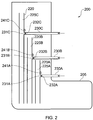
- FIG. 2 shows a further embodiment of the invention in which more than one tube member is provided.
- three tube members 220A, 220B, 220C are provided. It is to be understood that any suitable number of tube members may be provided.
- each tube member 220A, 220B, 220C has a single gas inlet 231A, 231B, 231C through which gas may be forced into an inner volume 225A, 225B, 225C of a respective tube member 220A, 220B, 220C.
- a check valve 232A, 232B, 232C is provided at each gas inlet 231A, 231B, 231C for this purpose.
- Each tube member has a liquid level sensor 241A, 241B, 241C respectively provided above the corresponding gas inlet 231A, 231B, 231C.
- a level of liquid in the fluid tank 205 reaches or exceeds a level of the liquid level sensor 241A, 241B, 241C, the apparatus is arranged to allow gaseous fluid to pass into the respective tube member 220A, 220B, 220C associated with the level sensor 241A, 241B, 241C.
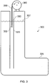
- FIG. 3 shows apparatus 300 not being according to an embodiment of the invention in which a gas inlet 332 for a tube member 320 is arranged to be movable in a vertical direction along at least a portion of a length of the tube member 320.
- the gas inlet 332 is provided at a free end of a hose 330 arranged to be wound on a drum 360. It is to be understood that the gas inlet 332 may be raised or lowered by winding of the drum 360.
- the apparatus 300 is arranged to determine a level 307 of liquid in the fluid tank 305 and to position the gas inlet 332 a suitable distance below the level 307 to provide effective circulation of fluid in the tank.
- a fluid level monitoring device is provided whereby the apparatus is arranged to determine a required vertical position of the gas inlet 332.
- the apparatus 300 is arranged to determine a level at which gaseous fluid is to be supplied to the tube member 320 by providing a prescribed pressure of gaseous fluid to the gas inlet 332 and lowering the gas inlet 332 until a flow rate of gaseous fluid through the gas inlet falls below a prescribed value due to the increasing head of pressure at the gas inlet 332.
- the apparatus is arranged to adjust a position of the gas inlet 332 accordingly.
- the gas inlet 332 may be arranged to be self-centering within the tube member 320.
- the gas inlet 332 may be arranged to be positioned substantially coaxially of the tube member when gas is flowing out from the gas inlet 332.
- Positions of nozzles through which gas flows out from the gas inlet 332 may be arranged to cause the gas inlet 332 to be self-centering.
- the nozzles may be arranged to direct gas in a radial direction out from the inlet 332.
- Reference herein to a vessel includes reference to any boat, ship, or other floating structure having at least one ballast tank in the form of a liquid storage tank.
Landscapes
- Engineering & Computer Science (AREA)
- Mechanical Engineering (AREA)
- General Engineering & Computer Science (AREA)
- Chemical & Material Sciences (AREA)
- Combustion & Propulsion (AREA)
- Ocean & Marine Engineering (AREA)
- General Health & Medical Sciences (AREA)
- Environmental & Geological Engineering (AREA)
- Health & Medical Sciences (AREA)
- Public Health (AREA)
- Toxicology (AREA)
- Filling Or Discharging Of Gas Storage Vessels (AREA)
- Jet Pumps And Other Pumps (AREA)
- Physical Or Chemical Processes And Apparatus (AREA)
- Treating Waste Gases (AREA)
- Structures Of Non-Positive Displacement Pumps (AREA)
Description
- The present invention relates to vessel having a ballast tank comprising a liquid pump apparatus arranged to recirculate liquid in the ballast tank.
-
JP2007113295 -
JP1207535 -
JP2006043674 JPH0290982 - In a first aspect of the invention there is provided a vessel having a ballast tank comprising liquid pump apparatus arranged to recirculate liquid in the ballast tank, the apparatus comprising: an immersion assembly comprising at least one immersion member having a liquid conduit provided therein along at least a portion of a length thereof, the immersion assembly being arranged whereby in use at least a portion of the immersion assembly is immersed in liquid to be pumped, the apparatus being arranged to provide a supply of gaseous fluid to liquid in the tank through the at least one immersion member at one of a plurality of vertically spaced apart locations of the assembly thereby to cause passage of liquid through the assembly from a liquid inlet aperture to a liquid outlet aperture of the assembly, the apparatus being configured configured such that, in use, the location at which gaseous fluid is supplied to the immersion assembly is dependent on the level of liquid in the ballast tank, wherein the apparatus comprises a liquid level monitoring device, the apparatus being arranged to determine the vertical position at which gaseous fluid is supplied to the liquid conduit based on a level of liquid in the tank.
- Embodiments of the invention have the advantage that pumping of liquid, for example to circulate or recirculate liquid in a liquid storage tank, may be reliably effected in a tank in which a level of liquid in the tank may vary over a relatively wide range. For example, a ballast tank of a ship or other vessel.
- It may be required to circulate water, for example in order to increase a concentration of a gas in the water (such as carbon dioxide) whereby aquatic nuisance species may be killed.
- A gas lift pump may be employed to circulate liquid in the tank, and to incorporate gas into the liquid as an integral part of the manner of operation of the gas lift pump. That is, the act of supplying gas to the immersion member of the gas lift pump in order to pump liquid through an inlet of the pump may be employed to increase an amount of the gas that is dissolved or otherwise incorporated into the liquid in order to achieve the purpose of killing aquatic nuisance species.
- In some embodiments the gas is injected into the immersion member. Other methods of dissolving or otherwise incorporating a gas into the liquid are also useful.
- A problem with known gas lift pumps is that as a pressure head of liquid in the liquid storage tank increases, increasingly high pressures of gas are required in order to force gas into a liquid conduit of the gas lift pump. The cost of providing apparatus to achieve these pressures is not insignificant. Furthermore, a weight and cost of the apparatus may be too high for a given application.
- The present invention overcomes these problems by providing a supply of gas to a liquid conduit of a gas lift pump at different vertical positions in a liquid storage tank. As the liquid level in the tank increases, a vertical position at which gaseous fluid is supplied is changed (increased) in order to ensure that a pressure of gaseous fluid required in order to supply gas into a liquid conduit does not exceed a prescribed value or range of values.
- Preferably the at least one immersion member has at least one liquid outlet aperture formed therein along at least a portion of a length of the fluid conduit thereof, the at least one outlet aperture being arranged to allow passage of liquid out from the immersion member therethrough.
- The at least one liquid outlet aperture may be of substantially the same size as the liquid inlet aperture of the immersion member.
- Thus, any particles, debris or aquatic species drawn into the immersion member through the liquid inlet aperture may be ejected through the liquid outlet aperture.
- Preferably the liquid inlet aperture has a diameter in the range of from around 15cm to around 80cm, preferably in the range from around 20cm to around 40cm.
- The immersion assembly may have a plurality of gaseous fluid inlets whereby the gaseous fluid may be supplied, the gaseous fluid inlets being provided at vertically spaced apart locations.
- The at least one immersion member may have a plurality of gaseous fluid inlets, the plurality of gaseous fluid inlets being provided at vertically spaced apart locations of the at least one immersion member.
- The apparatus may comprise a single immersion member.
- Alternatively the immersion assembly may comprise a plurality of immersion members, each immersion member having a liquid conduit therein along at least a portion of a length thereof, each of the immersion members having a gaseous fluid inlet whereby gaseous fluid may be supplied to the liquid conduit thereof, respective gaseous fluid inlets of respective immersion members being provided at vertically spaced apart locations with respect to one another.
- A plurality of the immersion members of the immersion assembly may have fluid conduits of different respective lengths.
- Preferably the prescribed range is determined such that for a level of liquid at or above a level at which a lowest gaseous fluid inlet delivers a supply of gaseous fluid, at least one gaseous fluid inlet is arranged to deliver a supply of gaseous fluid at a given moment in time.
- Alternatively or in addition a gaseous fluid inlet is arranged to be movable thereby to vary a vertical position at which gaseous fluid is supplied to the liquid conduit of the at least one immersion member.
- The gaseous fluid inlet may be arranged to be provided substantially coaxial of the liquid conduit.
- Preferably the gaseous fluid inlet is provided at a free end of a hose member, the hose member being arranged to be lowered into the liquid conduit of the at least one immersion member thereby to vary a vertical position at which gaseous fluid is supplied to the liquid conduit.
- The liquid level monitoring device may be provided at a prescribed distance above each gaseous fluid inlet of the assembly.
- Alternatively or in addition the apparatus may be arranged to determine the vertical position at which gaseous fluid is supplied to the liquid conduit based on a flow rate of gaseous fluid through a gaseous fluid inlet.
- The liquid conduit of the at least one immersion member may be substantially L-shaped.
- The liquid conduit of the at least one immersion member may comprise a substantially hollow tube member.
- The tube member may be of substantially circular cross-section.
- The gaseous fluid may be an inert gas. The gaseous fluid may comprise at least one selected from amongst carbon dioxide, nitrogen and oxygen. The gaseous fluid may substantially comprise carbon dioxide, nitrogen and oxygen. The gaseous fluid may consist essentially of carbon dioxide, nitrogen and oxygen.
- In a second aspect of the invention there is provided a method of recirculating liquid in a ballast tank of a vessel comprising: providing an immersion assembly comprising at least one immersion member having a liquid conduit provided therein along at least a portion of a length thereof; immersing at least a portion of the immersion assembly in liquid to be pumped; providing a supply of gaseous fluid to liquid in the tank through the at least one immersion member at one of a plurality of vertically spaced apart locations of the assembly thereby to cause passage of liquid through the assembly from a liquid inlet aperture to a liquid outlet aperture of the assembly by gas lift; the method comprising selecting a vertical location at which gaseous fluid is supplied to the immersion in dependence on the level of liquid in the ballast tank, the level of liquid being determined by reference to a liquid level monitoring device.
- The method may further comprise increasing a concentration of the gaseous fluid dissolved in the liquid.
- Preferably the gaseous fluid is a gaseous fluid selected to cause hypercapnia in aquatic nuisance species.
- Preferably the gaseous fluid is carbon dioxide.
- Embodiments of the invention will now be described with reference to the accompanying figures in which:
-
FIGURE 1 shows an embodiment of the invention in which liquid pump apparatus is installed in a ballast tank of a vessel for circulating liquid in the tank; -
FIGURE 2 shows a further embodiment of the invention in which liquid pump apparatus is installed in a ballast tank of a vessel; -
FIGURE 3 shows a still further embodiment of the invention in which liquid pump apparatus is installed in a ballast tank of a vessel. -
FIG. 1 shows an embodiment of the invention in which liquid pump apparatus is provided for circulation of liquid in a liquid storage tank. The apparatus may also be referred to as liquid circulation apparatus. - The apparatus is provided in which an
immersion member 120 in the form of a substantiallyhollow tube member 120 is provided in a substantially upright orientation within aballast tank 105. - In the embodiment shown the
tube member 120 is substantially 'L'-shaped, having abend portion 121 arranged to enable aliquid inlet 122 at a free end of thetube member 120 to project into a volume of the ballast tank that is displaced in a lateral (i.e. substantially horizontal) direction with respect to afree surface 107 of liquid within thetank 105. - The
tube member 120 has twogas inlets inner volume 125 of thetube member 120. The inlets are provided at vertically spaced apart locations along a length of thetube member 120. - Valves 132A, 132B are provided at the
respective inlets tube member 120. - In the embodiment shown in
FIG. 1 aliquid level sensor gas inlets liquid level sensor respective gas inlet - Other locations of liquid level sensor are also useful. For example, in some embodiments a liquid level sensor arranged to determine a liquid level by measuring a head of pressure of liquid at a prescribed location, such as a lower region of the
tank 105, may be employed. Other liquid level sensors are also useful. - The apparatus is arranged to supply a flow of gas through the
gas inlet 131A if theliquid level sensor 141A associated withinlet 131A indicates the presence of liquid at the level ofsensor 141A unlessliquid level sensor 141B indicates the presence of liquid at the level ofsensor 141B. In this case, the apparatus is arranged to allow a flow of gas throughgas inlet 131B and not throughgas inlet 131A. - It is to be understood that more than two gas inlets and corresponding liquid level sensors may be provided, the apparatus being arranged to allow a flow of gas through the gas inlet corresponding to the highest gas inlet having a
liquid level sensor liquid level sensor - Other arrangements are also useful. Thus, a gas inlet through which a flow of gas is allowed may be selected based on a level of liquid in the fluid tank as determined by a separate fluid level measuring device.
-
FIG. 2 shows a further embodiment of the invention in which more than one tube member is provided. In the embodiment ofFIG. 2 threetube members - In the embodiment shown each
tube member single gas inlet inner volume respective tube member check valve gas inlet - Each tube member has a
liquid level sensor gas inlet fluid tank 205 reaches or exceeds a level of theliquid level sensor respective tube member level sensor other tube member liquid level sensor other tube member liquid level sensor FIG. 1 . Other arrangements are also useful. -
FIG. 3 shows apparatus 300 not being according to an embodiment of the invention in which agas inlet 332 for atube member 320 is arranged to be movable in a vertical direction along at least a portion of a length of thetube member 320. In the embodiment shown thegas inlet 332 is provided at a free end of ahose 330 arranged to be wound on adrum 360. It is to be understood that thegas inlet 332 may be raised or lowered by winding of thedrum 360. - The
apparatus 300 is arranged to determine alevel 307 of liquid in thefluid tank 305 and to position the gas inlet 332 a suitable distance below thelevel 307 to provide effective circulation of fluid in the tank. - In some examples, a fluid level monitoring device is provided whereby the apparatus is arranged to determine a required vertical position of the
gas inlet 332. - In some examples, instead of providing a fluid level monitoring device, the
apparatus 300 is arranged to determine a level at which gaseous fluid is to be supplied to thetube member 320 by providing a prescribed pressure of gaseous fluid to thegas inlet 332 and lowering thegas inlet 332 until a flow rate of gaseous fluid through the gas inlet falls below a prescribed value due to the increasing head of pressure at thegas inlet 332. - As a level of liquid in the
tank 305 changes, for example due to discharge of liquid or addition of liquid, the apparatus is arranged to adjust a position of thegas inlet 332 accordingly. - Other arrangements are also useful.
- The
gas inlet 332 may be arranged to be self-centering within thetube member 320. In other words, thegas inlet 332 may be arranged to be positioned substantially coaxially of the tube member when gas is flowing out from thegas inlet 332. Positions of nozzles through which gas flows out from thegas inlet 332 may be arranged to cause thegas inlet 332 to be self-centering. For example the nozzles may be arranged to direct gas in a radial direction out from theinlet 332. - Reference herein to a vessel includes reference to any boat, ship, or other floating structure having at least one ballast tank in the form of a liquid storage tank.
- Throughout the description and claims of this specification, the words "comprise" and "contain" and variations of the words, for example "comprising" and "comprises", means "including but not limited to", and is not intended to (and does not) exclude other moieties, additives, components, integers or steps.
- Throughout the description and claims of this specification, the singular encompasses the plural unless the context otherwise requires. In particular, where the indefinite article is used, the specification is to be understood as contemplating plurality as well as singularity, unless the context requires otherwise.
- Features, integers, characteristics, compounds, chemical moieties or groups described in conjunction with a particular aspect, embodiment or example of the invention are to be understood to be applicable to any other aspect, embodiment or example described herein unless incompatible therewith.
Claims (14)
- A vessel having a ballast tank (105) comprising a liquid pump, the apparatus comprising:an immersion assembly comprising at least one immersion member (120) having a liquid conduit provided therein along at least a portion of a length thereof, the immersion assembly being arranged whereby in use at least a portion of the immersion assembly is immersed in liquid to be pumped,characterised in that:the apparatus is arranged to recirculate liquid in the ballast tank, the apparatus being arranged to provide a supply of gaseous fluid to liquid in the tank (105) through the at least one immersion member (120) at one of a plurality of vertically spaced apart locations (131A, 131B) of the assembly thereby to cause passage of liquid through the assembly from a liquid inlet aperture (122) to a liquid outlet aperture (125) of the assembly, the apparatus being configured such that, in use, the location at which gaseous fluid is supplied to the immersion assembly is dependent on the level of liquid in the ballast tank (105),the apparatus comprising a liquid level monitoring device (141A, 141B), the apparatus being arranged to determine the vertical position at which gaseous fluid is supplied to the liquid conduit based on a level of liquid in the ballast tank.
- A vessel as claimed in claim 1 wherein the at least one immersion member (120) has at least one liquid outlet aperture (125) formed therein along at least a portion of a length of the fluid conduit thereof, the at least one outlet aperture (125) being arranged to allow passage of liquid out from the immersion member (120) therethrough.
- A vessel as claimed in any preceding claim wherein the immersion assembly has a plurality of gaseous fluid inlets (131A, 131B) whereby the gaseous fluid may be supplied to the at least one immersion member (120), the gaseous fluid inlets (131A, 131B) being provided at vertically spaced apart locations.
- A vessel as claimed in claim 3 wherein the at least one immersion member (120) has a plurality of gaseous fluid inlets (131A, 131B), the plurality of gaseous fluid inlets being provided at vertically spaced apart locations of the at least one immersion member (120).
- A vessel as claimed in claim 3 wherein the immersion assembly comprises a single immersion member (120).
- A vessel as claimed in any one of claims 1 to 4 wherein the immersion assembly comprises a plurality of immersion members (220A, 220B, 220C), each immersion member having a liquid conduit (225A, 225B, 225C) therein along at least a portion of a length thereof, each of the immersion members (220A, 220B, 220C) having a gaseous fluid inlet (231A, 231B, 231C) whereby gaseous fluid may be supplied to the liquid conduit thereof, respective gaseous fluid inlets of respective immersion members being provided at vertically spaced apart locations with respect to one another.
- A vessel as claimed in any preceding claim wherein a gaseous fluid inlet (332) is arranged to be movable thereby to vary a vertical position at which gaseous fluid is supplied to the liquid conduit of the at least one immersion member (320).
- A vessel as claimed in any preceding claim wherein the liquid conduit of the at least one immersion member (120) is substantially L-shaped.
- A vessel as claimed in any preceding claim wherein the gaseous fluid is an inert gas.
- A vessel as claimed in any one of claims 1 to 8 wherein the gaseous fluid comprises at least one selected from amongst carbon dioxide, nitrogen and oxygen.
- A vessel as claimed in claim 10 wherein the gaseous fluid substantially comprises carbon dioxide, nitrogen and oxygen.
- A method of recirculating liquid in a ballast tank (105) of a vessel comprising:providing an immersion assembly comprising at least one immersion member (120) having a liquid conduit provided therein along at least a portion of a length thereof;immersing at least a portion of the immersion assembly in liquid to be pumped; andproviding a supply of gaseous fluid to liquid in the tank through the at least one immersion member at one of a plurality of vertically spaced apart locations of the assembly thereby to cause passage of liquid through the assembly from a liquid inlet (122) aperture to a liquid outlet aperture (125) of the assembly by gas lift,the method further comprising selecting a vertical location at which gaseous fluid is supplied to the immersion assembly in dependence on the level of liquid in the ballast tank, the level of liquid being determined by reference to a liquid level monitoring device (141A, 141B).
- A method as claimed in claim 12 further comprising increasing a concentration of the gaseous fluid dissolved in the liquid.
- A method as claimed in any one of claims 12 or 13 wherein the gaseous fluid comprises at least one selected from amongst carbon dioxide, nitrogen and oxygen.
Priority Applications (1)
| Application Number | Priority Date | Filing Date | Title |
|---|---|---|---|
| HRP20190571TT HRP20190571T1 (en) | 2009-05-08 | 2010-05-10 | Liquid pump apparatus and method |
Applications Claiming Priority (2)
| Application Number | Priority Date | Filing Date | Title |
|---|---|---|---|
| GB0907944.3A GB2470070B (en) | 2009-05-08 | 2009-05-08 | Liquid pump apparatus and method |
| PCT/GB2010/050751 WO2010128336A1 (en) | 2009-05-08 | 2010-05-10 | Liquid pump apparatus and method |
Publications (2)
| Publication Number | Publication Date |
|---|---|
| EP2430317A1 EP2430317A1 (en) | 2012-03-21 |
| EP2430317B1 true EP2430317B1 (en) | 2018-12-26 |
Family
ID=40833696
Family Applications (1)
| Application Number | Title | Priority Date | Filing Date |
|---|---|---|---|
| EP10718683.5A Not-in-force EP2430317B1 (en) | 2009-05-08 | 2010-05-10 | Liquid pump apparatus and method |
Country Status (12)
| Country | Link |
|---|---|
| US (1) | US8998585B2 (en) |
| EP (1) | EP2430317B1 (en) |
| JP (1) | JP5788382B2 (en) |
| KR (1) | KR101688549B1 (en) |
| CN (1) | CN102498299B (en) |
| AU (1) | AU2010244230B2 (en) |
| BR (1) | BRPI1013203A2 (en) |
| CY (1) | CY1121705T1 (en) |
| ES (1) | ES2717379T3 (en) |
| GB (1) | GB2470070B (en) |
| HR (1) | HRP20190571T1 (en) |
| WO (1) | WO2010128336A1 (en) |
Families Citing this family (6)
| Publication number | Priority date | Publication date | Assignee | Title |
|---|---|---|---|---|
| GB2470070B (en) | 2009-05-08 | 2012-05-16 | Coldharbour Marine Ltd | Liquid pump apparatus and method |
| HRP20201762T1 (en) * | 2010-06-29 | 2020-12-25 | Coldharbour Marine Limited | Shockwave generation device and method of delivering a shockwave |
| GB2497954A (en) | 2011-12-22 | 2013-07-03 | Coldharbour Marine Ltd | Gas lift pump with a sonic generator |
| EA034806B1 (en) | 2013-10-14 | 2020-03-24 | Колдхабэ Марин Лимитед | Gas conversion apparatus, fuel burning engine in combination with said apparatus and method of converting one or more reactant chemical species using said apparatus |
| KR101520586B1 (en) * | 2014-08-11 | 2015-05-15 | 연세대학교 산학협력단 | Apparatus and method for treating ballast water |
| KR20220029177A (en) | 2020-09-01 | 2022-03-08 | 동아대학교 산학협력단 | Ballast Tank using Air pressure |
Citations (2)
| Publication number | Priority date | Publication date | Assignee | Title |
|---|---|---|---|---|
| JPH0290982A (en) * | 1988-09-27 | 1990-03-30 | Matsushita Electric Works Ltd | Water pumping device for soil water treatment |
| JP2006043674A (en) * | 2004-08-04 | 2006-02-16 | Yasutoshi Takashima | Ballast water purifying system utilizing microorganisms |
Family Cites Families (36)
| Publication number | Priority date | Publication date | Assignee | Title |
|---|---|---|---|---|
| US347196A (en) * | 1886-08-10 | Julius g | ||
| US1054629A (en) | 1911-11-10 | 1913-02-25 | Archibald C Shenstone | Ore-agitator. |
| GB150698A (en) | 1919-08-29 | 1921-09-29 | Edwin Mcneill Rogers | Improvements in and relating to air-lift methods and apparatus for liquids |
| US1604419A (en) | 1923-06-15 | 1926-10-26 | Sullivan Machinery Co | Pumping mechanism |
| US1712695A (en) * | 1924-03-18 | 1929-05-14 | Salvage Process Corp | Pumping apparatus |
| US1698619A (en) * | 1925-06-11 | 1929-01-08 | Blow George | Liquid-lifting apparatus |
| US2632513A (en) * | 1945-07-04 | 1953-03-24 | Continental Oil Co | Gas lifting device for flowing multiple zone wells |
| GB624385A (en) * | 1946-03-16 | 1949-06-07 | Bengt Olsson | Improvements in and relating to pumping apparatus |
| US3172370A (en) * | 1961-10-16 | 1965-03-09 | Jean M Hoff | Continuous hydraulic ram |
| GB1063388A (en) * | 1963-09-23 | 1967-03-30 | Atomic Energy Authority Uk | Storage tanks for liquids |
| US3393519A (en) * | 1966-01-10 | 1968-07-23 | Davis Ind Inc | Method of installing liquid collection and pumping station in-situ |
| US3427989A (en) * | 1966-12-01 | 1969-02-18 | Otis Eng Corp | Well tools |
| US3433174A (en) * | 1967-01-13 | 1969-03-18 | Baker Oil Tools Inc | Subsurface well intermitter |
| DE1767497C3 (en) * | 1968-05-16 | 1974-05-16 | Engelbart Fritz Dipl Ing | Device for the biological cleaning of polluted water in ponds |
| GB1231377A (en) | 1969-09-10 | 1971-05-12 | ||
| US3694106A (en) * | 1970-06-08 | 1972-09-26 | Chicago Bridge & Iron Co | Air-lift pump with scalloped air-liberation rings, at two levels |
| SU500379A1 (en) * | 1971-09-22 | 1976-01-25 | Донецкий Ордена Трудового Красного Знамени Политехнический Институт | Airlift |
| JPS5489366A (en) * | 1977-12-27 | 1979-07-16 | Nippon Kokan Kk <Nkk> | Method and apparatus of mixing a storage liquid in a storage tank |
| JPS5837516Y2 (en) * | 1980-01-31 | 1983-08-24 | 株式会社クボタ | water treatment equipment |
| JPS56114897A (en) | 1980-02-07 | 1981-09-09 | Mitsubishi Electric Corp | Method for liquid-phase epitaxial growth |
| JPS60227887A (en) * | 1984-04-27 | 1985-11-13 | Tsukishima Kikai Co Ltd | Stirrer for digestion tank |
| EP0232000A1 (en) * | 1986-01-28 | 1987-08-12 | Raymond Anthony Breckner | Method and apparatus for pumping liquid |
| JPH01310200A (en) * | 1988-06-09 | 1989-12-14 | Hitachi Ltd | Controller for gas lift pump |
| DE4037899A1 (en) | 1990-11-28 | 1992-06-04 | Brechtelterra Spezialtiefbau U | DEVICE FOR CLEANING A FOUNTAIN PIPE AND FILTER PROTECTION IN WATER FOUNTAIN |
| US5735600A (en) * | 1996-06-04 | 1998-04-07 | Chicago Bridge & Iron Technical Services Company | Method and apparatus for automatically mixing drinking water in a reservoir |
| DE19700202C2 (en) | 1997-01-04 | 1999-05-06 | Aquaplus Brunnensanierung H Mu | Method and device for the mechanical cleaning of well shaft walls, pipelines or gravel layers behind a well shaft wall |
| JP3805920B2 (en) * | 1999-02-19 | 2006-08-09 | 株式会社細野建設 | Vacuum pumping device |
| US6402965B1 (en) | 1999-07-13 | 2002-06-11 | Oceanit Laboratories, Inc. | Ship ballast water ultrasonic treatment |
| FR2809179B1 (en) * | 2000-05-18 | 2003-09-19 | Ate Antipollution Tech Entpr | DEVICE FOR AUTOMATICALLY PRIMING FLUID COLLECTION RODS |
| US6722933B2 (en) * | 2001-05-25 | 2004-04-20 | Mh Systems, Inc. | Closed loop control of both pressure and content of ballast tank gases to at different times kill both aerobic and anaerobic organisms within ballast water |
| RU2248469C1 (en) | 2003-09-18 | 2005-03-20 | Газеев Наиль Хамидович | Gas-lifting plant |
| KR100542895B1 (en) * | 2003-12-22 | 2006-01-11 | 재단법인 포항산업과학연구원 | Electrolytic ballast water treatment method and treatment apparatus using sodium hypochlorite |
| JP2007113295A (en) | 2005-10-21 | 2007-05-10 | Honda Yutaka | Air lift pump |
| JP5386690B2 (en) | 2006-02-28 | 2014-01-15 | 三菱重工環境・化学エンジニアリング株式会社 | Liquid detoxification treatment apparatus and ship equipped with this apparatus |
| JP5466817B2 (en) * | 2007-09-03 | 2014-04-09 | シャープ株式会社 | Ozone water production equipment |
| GB2470070B (en) | 2009-05-08 | 2012-05-16 | Coldharbour Marine Ltd | Liquid pump apparatus and method |
-
2009
- 2009-05-08 GB GB0907944.3A patent/GB2470070B/en not_active Expired - Fee Related
-
2010
- 2010-05-10 AU AU2010244230A patent/AU2010244230B2/en not_active Ceased
- 2010-05-10 CN CN201080030642.6A patent/CN102498299B/en not_active Expired - Fee Related
- 2010-05-10 EP EP10718683.5A patent/EP2430317B1/en not_active Not-in-force
- 2010-05-10 US US13/376,507 patent/US8998585B2/en not_active Expired - Fee Related
- 2010-05-10 KR KR1020117029186A patent/KR101688549B1/en not_active Expired - Fee Related
- 2010-05-10 BR BRPI1013203A patent/BRPI1013203A2/en not_active Application Discontinuation
- 2010-05-10 ES ES10718683T patent/ES2717379T3/en active Active
- 2010-05-10 WO PCT/GB2010/050751 patent/WO2010128336A1/en not_active Ceased
- 2010-05-10 HR HRP20190571TT patent/HRP20190571T1/en unknown
- 2010-05-10 JP JP2012509096A patent/JP5788382B2/en not_active Expired - Fee Related
-
2019
- 2019-03-26 CY CY20191100351T patent/CY1121705T1/en unknown
Patent Citations (2)
| Publication number | Priority date | Publication date | Assignee | Title |
|---|---|---|---|---|
| JPH0290982A (en) * | 1988-09-27 | 1990-03-30 | Matsushita Electric Works Ltd | Water pumping device for soil water treatment |
| JP2006043674A (en) * | 2004-08-04 | 2006-02-16 | Yasutoshi Takashima | Ballast water purifying system utilizing microorganisms |
Also Published As
| Publication number | Publication date |
|---|---|
| JP2012526233A (en) | 2012-10-25 |
| GB2470070A (en) | 2010-11-10 |
| WO2010128336A1 (en) | 2010-11-11 |
| CN102498299B (en) | 2016-03-02 |
| AU2010244230A1 (en) | 2011-12-22 |
| HRP20190571T1 (en) | 2019-05-03 |
| AU2010244230B2 (en) | 2014-09-18 |
| GB2470070B (en) | 2012-05-16 |
| BRPI1013203A2 (en) | 2019-02-26 |
| CY1121705T1 (en) | 2020-07-31 |
| KR20130131501A (en) | 2013-12-04 |
| JP5788382B2 (en) | 2015-09-30 |
| KR101688549B1 (en) | 2016-12-21 |
| US20120091071A1 (en) | 2012-04-19 |
| GB0907944D0 (en) | 2009-06-24 |
| ES2717379T3 (en) | 2019-06-20 |
| CN102498299A (en) | 2012-06-13 |
| EP2430317A1 (en) | 2012-03-21 |
| HK1147301A1 (en) | 2011-08-05 |
| US8998585B2 (en) | 2015-04-07 |
Similar Documents
| Publication | Publication Date | Title |
|---|---|---|
| AU2010244230B2 (en) | Liquid pump apparatus and method | |
| AU2011345443B2 (en) | Technical system, method and uses for dosing of at least one liquid treatment means into injection water to an injection well | |
| US8123957B2 (en) | Method and apparatus of submersible intake equipment | |
| KR101752689B1 (en) | Floating type water purifying system | |
| WO2010092569A1 (en) | Device and method for dissolving gas into a liquid | |
| US10139014B2 (en) | Device for controlling the filling of a pipe as it is being laid in a stretch of water, and associated assembly and method | |
| US9586184B2 (en) | Air-powered water circulation systems for ponds, lakes, municipal water tanks, and other bodies of water | |
| AU2015326712A1 (en) | Apparatus for controlling injection pressure in assisted offshore oil recovery | |
| WO2012118000A1 (en) | Water hammer generation device | |
| CN119822531B (en) | A reoxygenation system for water quality improvement | |
| US10052573B2 (en) | Apparatus and method for water treatment via vertical water movement through a funnel | |
| US8622371B1 (en) | Anchored aerator | |
| US7950452B2 (en) | Anti-fouling system for offshore drilling structures | |
| CN219430892U (en) | Water intake system | |
| JP6810645B2 (en) | Drainage system for marine desulfurization equipment | |
| KR200374562Y1 (en) | Adjustable-Height Air Lifter | |
| JP7697314B2 (en) | Method for remediating soil and/or groundwater | |
| KR101935631B1 (en) | Red tide reducing apparatus | |
| CN223329794U (en) | Nuclear power plant cold source water intake sea biology cleaning structure | |
| JP2014050820A (en) | Decarboxylation processing unit | |
| KR20200142963A (en) | Gas dissolution apparatus and micro bubble generator comprising same | |
| RU2450172C2 (en) | Method of water lift and device to this end | |
| JP2006142131A (en) | Gas dissolved water supply device | |
| CN103828760A (en) | Efficient aerator | |
| KR20210006648A (en) | A device for supplying pre-treated wastewater to an aeration tank evenly for 24 hours |
Legal Events
| Date | Code | Title | Description |
|---|---|---|---|
| PUAI | Public reference made under article 153(3) epc to a published international application that has entered the european phase |
Free format text: ORIGINAL CODE: 0009012 |
|
| 17P | Request for examination filed |
Effective date: 20111205 |
|
| AK | Designated contracting states |
Kind code of ref document: A1 Designated state(s): AL AT BE BG CH CY CZ DE DK EE ES FI FR GB GR HR HU IE IS IT LI LT LU LV MC MK MT NL NO PL PT RO SE SI SK SM TR |
|
| DAX | Request for extension of the european patent (deleted) | ||
| STAA | Information on the status of an ep patent application or granted ep patent |
Free format text: STATUS: EXAMINATION IS IN PROGRESS |
|
| 17Q | First examination report despatched |
Effective date: 20170822 |
|
| REG | Reference to a national code |
Ref country code: DE Ref legal event code: R079 Ref document number: 602010056039 Country of ref document: DE Free format text: PREVIOUS MAIN CLASS: F04F0001180000 Ipc: B63J0004000000 |
|
| GRAP | Despatch of communication of intention to grant a patent |
Free format text: ORIGINAL CODE: EPIDOSNIGR1 |
|
| STAA | Information on the status of an ep patent application or granted ep patent |
Free format text: STATUS: GRANT OF PATENT IS INTENDED |
|
| RIC1 | Information provided on ipc code assigned before grant |
Ipc: F04F 1/18 20060101ALI20180406BHEP Ipc: E21B 43/12 20060101ALI20180406BHEP Ipc: B63B 23/24 20060101ALI20180406BHEP Ipc: B63J 4/00 20060101AFI20180406BHEP |
|
| INTG | Intention to grant announced |
Effective date: 20180430 |
|
| GRAS | Grant fee paid |
Free format text: ORIGINAL CODE: EPIDOSNIGR3 |
|
| GRAA | (expected) grant |
Free format text: ORIGINAL CODE: 0009210 |
|
| STAA | Information on the status of an ep patent application or granted ep patent |
Free format text: STATUS: THE PATENT HAS BEEN GRANTED |
|
| AK | Designated contracting states |
Kind code of ref document: B1 Designated state(s): AL AT BE BG CH CY CZ DE DK EE ES FI FR GB GR HR HU IE IS IT LI LT LU LV MC MK MT NL NO PL PT RO SE SI SK SM TR |
|
| REG | Reference to a national code |
Ref country code: GB Ref legal event code: FG4D |
|
| REG | Reference to a national code |
Ref country code: CH Ref legal event code: EP |
|
| REG | Reference to a national code |
Ref country code: AT Ref legal event code: REF Ref document number: 1081037 Country of ref document: AT Kind code of ref document: T Effective date: 20190115 |
|
| REG | Reference to a national code |
Ref country code: DE Ref legal event code: R096 Ref document number: 602010056039 Country of ref document: DE |
|
| REG | Reference to a national code |
Ref country code: IE Ref legal event code: FG4D |
|
| REG | Reference to a national code |
Ref country code: HR Ref legal event code: TUEP Ref document number: P20190571 Country of ref document: HR |
|
| RAP2 | Party data changed (patent owner data changed or rights of a patent transferred) |
Owner name: COLDHARBOUR MARINE LIMITED |
|
| PG25 | Lapsed in a contracting state [announced via postgrant information from national office to epo] |
Ref country code: LV Free format text: LAPSE BECAUSE OF FAILURE TO SUBMIT A TRANSLATION OF THE DESCRIPTION OR TO PAY THE FEE WITHIN THE PRESCRIBED TIME-LIMIT Effective date: 20181226 Ref country code: FI Free format text: LAPSE BECAUSE OF FAILURE TO SUBMIT A TRANSLATION OF THE DESCRIPTION OR TO PAY THE FEE WITHIN THE PRESCRIBED TIME-LIMIT Effective date: 20181226 Ref country code: LT Free format text: LAPSE BECAUSE OF FAILURE TO SUBMIT A TRANSLATION OF THE DESCRIPTION OR TO PAY THE FEE WITHIN THE PRESCRIBED TIME-LIMIT Effective date: 20181226 Ref country code: BG Free format text: LAPSE BECAUSE OF FAILURE TO SUBMIT A TRANSLATION OF THE DESCRIPTION OR TO PAY THE FEE WITHIN THE PRESCRIBED TIME-LIMIT Effective date: 20190326 |
|
| REG | Reference to a national code |
Ref country code: NL Ref legal event code: MP Effective date: 20181226 |
|
| REG | Reference to a national code |
Ref country code: HR Ref legal event code: T1PR Ref document number: P20190571 Country of ref document: HR |
|
| REG | Reference to a national code |
Ref country code: NO Ref legal event code: T2 Effective date: 20181226 |
|
| REG | Reference to a national code |
Ref country code: LT Ref legal event code: MG4D |
|
| PG25 | Lapsed in a contracting state [announced via postgrant information from national office to epo] |
Ref country code: AL Free format text: LAPSE BECAUSE OF FAILURE TO SUBMIT A TRANSLATION OF THE DESCRIPTION OR TO PAY THE FEE WITHIN THE PRESCRIBED TIME-LIMIT Effective date: 20181226 Ref country code: SE Free format text: LAPSE BECAUSE OF FAILURE TO SUBMIT A TRANSLATION OF THE DESCRIPTION OR TO PAY THE FEE WITHIN THE PRESCRIBED TIME-LIMIT Effective date: 20181226 |
|
| REG | Reference to a national code |
Ref country code: HR Ref legal event code: ODRP Ref document number: P20190571 Country of ref document: HR Payment date: 20190521 Year of fee payment: 10 |
|
| REG | Reference to a national code |
Ref country code: GR Ref legal event code: EP Ref document number: 20190400976 Country of ref document: GR Effective date: 20190524 |
|
| REG | Reference to a national code |
Ref country code: AT Ref legal event code: MK05 Ref document number: 1081037 Country of ref document: AT Kind code of ref document: T Effective date: 20181226 |
|
| REG | Reference to a national code |
Ref country code: ES Ref legal event code: FG2A Ref document number: 2717379 Country of ref document: ES Kind code of ref document: T3 Effective date: 20190620 |
|
| PG25 | Lapsed in a contracting state [announced via postgrant information from national office to epo] |
Ref country code: NL Free format text: LAPSE BECAUSE OF FAILURE TO SUBMIT A TRANSLATION OF THE DESCRIPTION OR TO PAY THE FEE WITHIN THE PRESCRIBED TIME-LIMIT Effective date: 20181226 |
|
| PG25 | Lapsed in a contracting state [announced via postgrant information from national office to epo] |
Ref country code: PL Free format text: LAPSE BECAUSE OF FAILURE TO SUBMIT A TRANSLATION OF THE DESCRIPTION OR TO PAY THE FEE WITHIN THE PRESCRIBED TIME-LIMIT Effective date: 20181226 Ref country code: CZ Free format text: LAPSE BECAUSE OF FAILURE TO SUBMIT A TRANSLATION OF THE DESCRIPTION OR TO PAY THE FEE WITHIN THE PRESCRIBED TIME-LIMIT Effective date: 20181226 Ref country code: PT Free format text: LAPSE BECAUSE OF FAILURE TO SUBMIT A TRANSLATION OF THE DESCRIPTION OR TO PAY THE FEE WITHIN THE PRESCRIBED TIME-LIMIT Effective date: 20190426 |
|
| PG25 | Lapsed in a contracting state [announced via postgrant information from national office to epo] |
Ref country code: RO Free format text: LAPSE BECAUSE OF FAILURE TO SUBMIT A TRANSLATION OF THE DESCRIPTION OR TO PAY THE FEE WITHIN THE PRESCRIBED TIME-LIMIT Effective date: 20181226 Ref country code: EE Free format text: LAPSE BECAUSE OF FAILURE TO SUBMIT A TRANSLATION OF THE DESCRIPTION OR TO PAY THE FEE WITHIN THE PRESCRIBED TIME-LIMIT Effective date: 20181226 Ref country code: SM Free format text: LAPSE BECAUSE OF FAILURE TO SUBMIT A TRANSLATION OF THE DESCRIPTION OR TO PAY THE FEE WITHIN THE PRESCRIBED TIME-LIMIT Effective date: 20181226 Ref country code: IS Free format text: LAPSE BECAUSE OF FAILURE TO SUBMIT A TRANSLATION OF THE DESCRIPTION OR TO PAY THE FEE WITHIN THE PRESCRIBED TIME-LIMIT Effective date: 20190426 Ref country code: SK Free format text: LAPSE BECAUSE OF FAILURE TO SUBMIT A TRANSLATION OF THE DESCRIPTION OR TO PAY THE FEE WITHIN THE PRESCRIBED TIME-LIMIT Effective date: 20181226 |
|
| REG | Reference to a national code |
Ref country code: DE Ref legal event code: R097 Ref document number: 602010056039 Country of ref document: DE |
|
| PG25 | Lapsed in a contracting state [announced via postgrant information from national office to epo] |
Ref country code: DK Free format text: LAPSE BECAUSE OF FAILURE TO SUBMIT A TRANSLATION OF THE DESCRIPTION OR TO PAY THE FEE WITHIN THE PRESCRIBED TIME-LIMIT Effective date: 20181226 Ref country code: AT Free format text: LAPSE BECAUSE OF FAILURE TO SUBMIT A TRANSLATION OF THE DESCRIPTION OR TO PAY THE FEE WITHIN THE PRESCRIBED TIME-LIMIT Effective date: 20181226 |
|
| PLBE | No opposition filed within time limit |
Free format text: ORIGINAL CODE: 0009261 |
|
| STAA | Information on the status of an ep patent application or granted ep patent |
Free format text: STATUS: NO OPPOSITION FILED WITHIN TIME LIMIT |
|
| 26N | No opposition filed |
Effective date: 20190927 |
|
| REG | Reference to a national code |
Ref country code: CH Ref legal event code: PL |
|
| PG25 | Lapsed in a contracting state [announced via postgrant information from national office to epo] |
Ref country code: MC Free format text: LAPSE BECAUSE OF FAILURE TO SUBMIT A TRANSLATION OF THE DESCRIPTION OR TO PAY THE FEE WITHIN THE PRESCRIBED TIME-LIMIT Effective date: 20181226 Ref country code: CH Free format text: LAPSE BECAUSE OF NON-PAYMENT OF DUE FEES Effective date: 20190531 Ref country code: LI Free format text: LAPSE BECAUSE OF NON-PAYMENT OF DUE FEES Effective date: 20190531 |
|
| REG | Reference to a national code |
Ref country code: BE Ref legal event code: MM Effective date: 20190531 |
|
| PG25 | Lapsed in a contracting state [announced via postgrant information from national office to epo] |
Ref country code: SI Free format text: LAPSE BECAUSE OF FAILURE TO SUBMIT A TRANSLATION OF THE DESCRIPTION OR TO PAY THE FEE WITHIN THE PRESCRIBED TIME-LIMIT Effective date: 20181226 Ref country code: LU Free format text: LAPSE BECAUSE OF NON-PAYMENT OF DUE FEES Effective date: 20190510 |
|
| PG25 | Lapsed in a contracting state [announced via postgrant information from national office to epo] |
Ref country code: TR Free format text: LAPSE BECAUSE OF FAILURE TO SUBMIT A TRANSLATION OF THE DESCRIPTION OR TO PAY THE FEE WITHIN THE PRESCRIBED TIME-LIMIT Effective date: 20181226 |
|
| PG25 | Lapsed in a contracting state [announced via postgrant information from national office to epo] |
Ref country code: IE Free format text: LAPSE BECAUSE OF NON-PAYMENT OF DUE FEES Effective date: 20190510 |
|
| PG25 | Lapsed in a contracting state [announced via postgrant information from national office to epo] |
Ref country code: BE Free format text: LAPSE BECAUSE OF NON-PAYMENT OF DUE FEES Effective date: 20190531 |
|
| REG | Reference to a national code |
Ref country code: HR Ref legal event code: ODRP Ref document number: P20190571 Country of ref document: HR Payment date: 20200608 Year of fee payment: 11 |
|
| PGFP | Annual fee paid to national office [announced via postgrant information from national office to epo] |
Ref country code: DE Payment date: 20200618 Year of fee payment: 11 Ref country code: FR Payment date: 20200529 Year of fee payment: 11 |
|
| PGFP | Annual fee paid to national office [announced via postgrant information from national office to epo] |
Ref country code: HR Payment date: 20200608 Year of fee payment: 11 Ref country code: IT Payment date: 20200529 Year of fee payment: 11 |
|
| PGFP | Annual fee paid to national office [announced via postgrant information from national office to epo] |
Ref country code: ES Payment date: 20200728 Year of fee payment: 11 Ref country code: CY Payment date: 20200611 Year of fee payment: 11 |
|
| PG25 | Lapsed in a contracting state [announced via postgrant information from national office to epo] |
Ref country code: HU Free format text: LAPSE BECAUSE OF FAILURE TO SUBMIT A TRANSLATION OF THE DESCRIPTION OR TO PAY THE FEE WITHIN THE PRESCRIBED TIME-LIMIT; INVALID AB INITIO Effective date: 20100510 Ref country code: MT Free format text: LAPSE BECAUSE OF FAILURE TO SUBMIT A TRANSLATION OF THE DESCRIPTION OR TO PAY THE FEE WITHIN THE PRESCRIBED TIME-LIMIT Effective date: 20181226 |
|
| PGFP | Annual fee paid to national office [announced via postgrant information from national office to epo] |
Ref country code: GR Payment date: 20210521 Year of fee payment: 12 Ref country code: NO Payment date: 20210521 Year of fee payment: 12 |
|
| PGFP | Annual fee paid to national office [announced via postgrant information from national office to epo] |
Ref country code: GB Payment date: 20210525 Year of fee payment: 12 |
|
| REG | Reference to a national code |
Ref country code: DE Ref legal event code: R119 Ref document number: 602010056039 Country of ref document: DE |
|
| REG | Reference to a national code |
Ref country code: HR Ref legal event code: PBON Ref document number: P20190571 Country of ref document: HR Effective date: 20210510 |
|
| PG25 | Lapsed in a contracting state [announced via postgrant information from national office to epo] |
Ref country code: HR Free format text: LAPSE BECAUSE OF NON-PAYMENT OF DUE FEES Effective date: 20210510 Ref country code: CY Free format text: LAPSE BECAUSE OF NON-PAYMENT OF DUE FEES Effective date: 20210510 |
|
| PG25 | Lapsed in a contracting state [announced via postgrant information from national office to epo] |
Ref country code: DE Free format text: LAPSE BECAUSE OF NON-PAYMENT OF DUE FEES Effective date: 20211201 |
|
| PG25 | Lapsed in a contracting state [announced via postgrant information from national office to epo] |
Ref country code: FR Free format text: LAPSE BECAUSE OF NON-PAYMENT OF DUE FEES Effective date: 20210531 |
|
| PG25 | Lapsed in a contracting state [announced via postgrant information from national office to epo] |
Ref country code: MK Free format text: LAPSE BECAUSE OF FAILURE TO SUBMIT A TRANSLATION OF THE DESCRIPTION OR TO PAY THE FEE WITHIN THE PRESCRIBED TIME-LIMIT Effective date: 20181226 |
|
| REG | Reference to a national code |
Ref country code: ES Ref legal event code: FD2A Effective date: 20220801 |
|
| PG25 | Lapsed in a contracting state [announced via postgrant information from national office to epo] |
Ref country code: ES Free format text: LAPSE BECAUSE OF NON-PAYMENT OF DUE FEES Effective date: 20210511 |
|
| REG | Reference to a national code |
Ref country code: NO Ref legal event code: MMEP |
|
| GBPC | Gb: european patent ceased through non-payment of renewal fee |
Effective date: 20220510 |
|
| PG25 | Lapsed in a contracting state [announced via postgrant information from national office to epo] |
Ref country code: NO Free format text: LAPSE BECAUSE OF NON-PAYMENT OF DUE FEES Effective date: 20220531 |
|
| PG25 | Lapsed in a contracting state [announced via postgrant information from national office to epo] |
Ref country code: GR Free format text: LAPSE BECAUSE OF NON-PAYMENT OF DUE FEES Effective date: 20221208 |
|
| PG25 | Lapsed in a contracting state [announced via postgrant information from national office to epo] |
Ref country code: IT Free format text: LAPSE BECAUSE OF NON-PAYMENT OF DUE FEES Effective date: 20200510 Ref country code: GB Free format text: LAPSE BECAUSE OF NON-PAYMENT OF DUE FEES Effective date: 20220510 |
|
| PG25 | Lapsed in a contracting state [announced via postgrant information from national office to epo] |
Ref country code: IT Free format text: LAPSE BECAUSE OF NON-PAYMENT OF DUE FEES Effective date: 20210510 |