EP2429249A1 - Method for inter-cell interference coordination in a cellular communication network, network element of a cellular communication network, and cellular communication network - Google Patents
Method for inter-cell interference coordination in a cellular communication network, network element of a cellular communication network, and cellular communication network Download PDFInfo
- Publication number
- EP2429249A1 EP2429249A1 EP10290488A EP10290488A EP2429249A1 EP 2429249 A1 EP2429249 A1 EP 2429249A1 EP 10290488 A EP10290488 A EP 10290488A EP 10290488 A EP10290488 A EP 10290488A EP 2429249 A1 EP2429249 A1 EP 2429249A1
- Authority
- EP
- European Patent Office
- Prior art keywords
- pico
- base station
- cell
- transmission resources
- macro
- Prior art date
- Legal status (The legal status is an assumption and is not a legal conclusion. Google has not performed a legal analysis and makes no representation as to the accuracy of the status listed.)
- Granted
Links
Images


Classifications
-
- H—ELECTRICITY
- H04—ELECTRIC COMMUNICATION TECHNIQUE
- H04W—WIRELESS COMMUNICATION NETWORKS
- H04W52/00—Power management, e.g. TPC [Transmission Power Control], power saving or power classes
- H04W52/04—TPC
- H04W52/18—TPC being performed according to specific parameters
- H04W52/24—TPC being performed according to specific parameters using SIR [Signal to Interference Ratio] or other wireless path parameters
- H04W52/243—TPC being performed according to specific parameters using SIR [Signal to Interference Ratio] or other wireless path parameters taking into account interferences
- H04W52/244—Interferences in heterogeneous networks, e.g. among macro and femto or pico cells or other sector / system interference [OSI]
-
- H—ELECTRICITY
- H04—ELECTRIC COMMUNICATION TECHNIQUE
- H04W—WIRELESS COMMUNICATION NETWORKS
- H04W16/00—Network planning, e.g. coverage or traffic planning tools; Network deployment, e.g. resource partitioning or cells structures
- H04W16/24—Cell structures
- H04W16/32—Hierarchical cell structures
-
- H—ELECTRICITY
- H04—ELECTRIC COMMUNICATION TECHNIQUE
- H04W—WIRELESS COMMUNICATION NETWORKS
- H04W16/00—Network planning, e.g. coverage or traffic planning tools; Network deployment, e.g. resource partitioning or cells structures
- H04W16/02—Resource partitioning among network components, e.g. reuse partitioning
- H04W16/04—Traffic adaptive resource partitioning
-
- H—ELECTRICITY
- H04—ELECTRIC COMMUNICATION TECHNIQUE
- H04W—WIRELESS COMMUNICATION NETWORKS
- H04W52/00—Power management, e.g. TPC [Transmission Power Control], power saving or power classes
- H04W52/04—TPC
- H04W52/18—TPC being performed according to specific parameters
- H04W52/24—TPC being performed according to specific parameters using SIR [Signal to Interference Ratio] or other wireless path parameters
- H04W52/243—TPC being performed according to specific parameters using SIR [Signal to Interference Ratio] or other wireless path parameters taking into account interferences
-
- H—ELECTRICITY
- H04—ELECTRIC COMMUNICATION TECHNIQUE
- H04W—WIRELESS COMMUNICATION NETWORKS
- H04W52/00—Power management, e.g. TPC [Transmission Power Control], power saving or power classes
- H04W52/04—TPC
- H04W52/30—TPC using constraints in the total amount of available transmission power
-
- H—ELECTRICITY
- H04—ELECTRIC COMMUNICATION TECHNIQUE
- H04W—WIRELESS COMMUNICATION NETWORKS
- H04W52/00—Power management, e.g. TPC [Transmission Power Control], power saving or power classes
- H04W52/04—TPC
- H04W52/30—TPC using constraints in the total amount of available transmission power
- H04W52/34—TPC management, i.e. sharing limited amount of power among users or channels or data types, e.g. cell loading
- H04W52/343—TPC management, i.e. sharing limited amount of power among users or channels or data types, e.g. cell loading taking into account loading or congestion level
-
- H—ELECTRICITY
- H04—ELECTRIC COMMUNICATION TECHNIQUE
- H04W—WIRELESS COMMUNICATION NETWORKS
- H04W72/00—Local resource management
- H04W72/04—Wireless resource allocation
-
- H—ELECTRICITY
- H04—ELECTRIC COMMUNICATION TECHNIQUE
- H04W—WIRELESS COMMUNICATION NETWORKS
- H04W72/00—Local resource management
- H04W72/50—Allocation or scheduling criteria for wireless resources
- H04W72/52—Allocation or scheduling criteria for wireless resources based on load
-
- H—ELECTRICITY
- H04—ELECTRIC COMMUNICATION TECHNIQUE
- H04W—WIRELESS COMMUNICATION NETWORKS
- H04W16/00—Network planning, e.g. coverage or traffic planning tools; Network deployment, e.g. resource partitioning or cells structures
- H04W16/02—Resource partitioning among network components, e.g. reuse partitioning
- H04W16/06—Hybrid resource partitioning, e.g. channel borrowing
- H04W16/08—Load shedding arrangements
-
- H—ELECTRICITY
- H04—ELECTRIC COMMUNICATION TECHNIQUE
- H04W—WIRELESS COMMUNICATION NETWORKS
- H04W72/00—Local resource management
- H04W72/50—Allocation or scheduling criteria for wireless resources
- H04W72/54—Allocation or scheduling criteria for wireless resources based on quality criteria
- H04W72/541—Allocation or scheduling criteria for wireless resources based on quality criteria using the level of interference
Definitions
- the present invention refers to a method for inter-cell interference coordination (ICIC) in an cellular communication network comprising multiple macro base stations controlling a macro cell of the cellular network and at least one pico base station (also referred to as low power base station) controlling a pico cell (also referred to as low power cell) of the cellular network, said pico cell being located at least partially within at least one macro cell.
- the present invention refers to a network element of such a cellular communication network.
- the present invention refers to a cellular communication network comprising multiple base stations controlling a macro cell of the cellular network and at least one pico base station controlling a pico cell of the cellular network, said pico cell being located at least partially within at least one macro cell.
- Inter-cell interference coordination is known in the art.
- a base station (a so-called eNodeB) of the long term evolution (LTE) cellular radio access network and its successor LTE advanced may coordinate the allocation of radio transmission resources with neighbouring base stations in order to reduce inter-cell interference and to improve an overall spectral efficiency and/or an overall throughput of the radio access network.
- LTE long term evolution
- a known approach of inter-cell interference coordination is fractional frequency reuse.
- a base station of a macro cell uses a first portion of radio transmission resources for transmitting a radio signal, a transmission power of which can reach a maximum transmit power.
- the base station uses another portion of the transmission resources with a limited transmission power in order to reduce inter-cell interference with neighbouring macro cells.
- a base station of the neighbouring macro cell may use the further portion of the transmission resources for communicating with a terminal located at a cell edge of said neighbouring macro cell. Therefore, the base station may use all portions of the transmission resources for terminals located in an inner region of the cell and use only a part of the transmission resources for terminals located in a cell edge region of the cell.
- inter-cell interference coordination allow to reduce the interference of neighbouring macro cells.
- the known approaches of inter-cell interference coordination do not allow for control the interference between a macro cell and a pico cell located within the macro cell.
- the object of the present invention is to provide a method, a network element, and a cellular communication network that improve a throughput of cells of a cellular communication network and/or the spectral efficiency of transmission resources of the cellular network.
- a method for inter-cell interference coordination in a cellular communication network comprising multiple macro base stations controlling at least one of multiple macro cells of the cellular network and at least one pico base station controlling at least one pico cell of the cellular network, said pico cell being located at least partially within at least one macro cell, said method comprising: assigning a first portion of radio transmission resources of the cellular network and a second portion of said transmission resources to each of said multiple macro base stations for transmitting a radio signal using the first portion and the second portion of said transmission resources and limiting a maximum transmission power of the radio signal to be transmitted using the second portion to a transmit power limit, the transmit power limit being less than a maximum transmit power of the signal to be transmitted using the first portion, wherein the method further comprises assigning the second portion of said transmission resources to the pico base station for transmitting the radio signal using the second portion of said transmission resources.
- at least a part of the first portion is assigned to the pico base station, too.
- a base station of a macro cell uses a transmission power that is limited to said transmit power limit when transmitting a radio signal using the second portion of the transmission resources so that a pico base station of the pico cell may use the second portion for communicating with terminals registered with the pico base station with low interference.
- the pico base stations uses the second portion of transmission resources for communicating with terminals located within an border region of the pico cell, i.e., for communicating with terminals located rather far away from the pico cell base station. Limiting the maximum transmission power of the radio signal transmitted by the macro base stations using the second portion allows not only for reducing an interference between the macro cells and the pico cells embedded therein but also increases a cell size of the pico cell.
- the radio resources may be partitioned into the first portion and the second portion according to time. Time may be subdivided into multiple consecutive time units. A first subset of these time units may correspond to the first portion, whereas a second subset of the time units may correspond to the second portion.
- the radio transmission resources are partitioned according to frequency, i.e., the first portion corresponds to a first frequency range and/or the second portion corresponds to a second frequency range of the transmission resources.
- transmission resources are subdivided in the frequency domain into multiple consecutive physical resource blocks (PRB).
- PRB physical resource blocks
- time domain the transmission resources are subdivided into multiple consecutive subframes of a radio frame.
- the first portion may correspond to a set of one or more physical resource blocks and/or the second portion may correspond to a second set of one or more physical resource blocks, the first and the second set being disjunctive.
- the first portion and/or the second portion may correspond to a set of consecutive physical resource blocks. It should be noted that the present invention may be applied in connection with LTE but can also be applied in connection with a cellular communication network of a different type.
- the cellular network has a group of multiple pico base stations and the method comprises assigning the second portion of the transmission resources to all pico base stations of said group.
- all pico base stations of that said group may transmit a radio signal within the second portion of the transmission resources.
- all pico base stations of the group preferably all pico base stations of the cellular network, use the identical second portion of the transmission resources in order to communicate with at least one terminal registered with that pico base station.
- the transmit power limit is a predefined static value that can be changed manually only. In another embodiment, the transmit power limit is determined semi-statically or dynamically depending on an operating status of the cellular communication network, preferably the macro base stations, the pico base station, and/or the terminal.
- the method comprises determining at least one characteristic of communication traffic related to at least one terminal registered with a macro base station and/or the pico base station and determining the transmit power limit depending on said characteristic. Adapting the transmit power limit to the traffic allows for adaptively changing a size, i.e., a coverage area, of the pico cell.
- determining the at least one characteristic comprises retrieving buffer status information of a transmit buffer of a macro base station, a pico base station and/or the terminal.
- Information about the transmit buffer allows from estimating the amount of data to be transferred between the macro base station or the pico base station and the terminal. For instance, if the terminal is registered with the pico base station and is communicating with the pico base stations using the second portion of the transmission resources and if the transmit buffer has many data packets stored to be transmitted over the transmission resources then the transmit power level may be decreased in order to reduce interference between the pico cell and the macro cell in which the pico cell is embedded so that the throughput for the data communication between the pico base station and the terminal can be improved.
- the method comprises determining the transmit power limit depending on a parameter indicating a density of terminals within a macro cell and/or a pico cell, preferably depending on a number of terminals registered with a certain macro base station or pico base station. For instance, a number of terminals registered with the pico base station can be determined. If the number of terminals registered with the pico base station is low then the transmit power limit may be decreased in the macro base station in order to increase the coverage area.of the corresponding pico cell so that additional terminals can register with the pico base station.
- the method comprises assigning the first portion of the transmission resources to the pico cell and limiting the transmission power of a radio signal to be transmitted by the pico base station using the first portion to a pico cell transmit power limit, the pico cell transmit power limit being less than a maximum transmit power of the signal to be transmitted within the pico cell by the pico base station.
- the method comprises scheduling at least some terminals registered with the pico base station and located at a border region of the pico cell for transmissions using the second portion of the transmission resources and/or scheduling at least some terminals registered with a macro base station and located at the border region of the pico cell for transmissions using the first portion of the transmission resources and/or scheduling at least some terminals registered with a macro base station and located outside of any border region of a pico cell for transmission using the second portion of the transmission resources.
- Said scheduling may be performed by a scheduler of a macro base station and/or a scheduler of the pico base station.
- the transmit power limit is determined separately for each macro base station. Determining separate values of the transmit power limit for the individual macro base stations allows for a fine-grained inter-cell interference coordination.
- the transmit power limit is determined as a single value for multiple macro base stations. Defining a single value simplifies the implementation of the method.
- the partitioning of the radio transmission resources into the first portion and the second portion is static.
- the first portion and/or the second portion is determined depending on said characteristic of the traffic related to at least one terminal and/or said parameter indicating the density of terminals. That is, the first portion and/or the second portion may be determined e.g. semi-statically depending on the operating status of the cellular network.
- the transmission resources comprise multiple channels, each of them occupying a separate frequency band, and wherein the second portion of the radio resources corresponds to one of said multiple channels.
- the transmission resources comprise a single channel subdivided into multiple sub-bands, the first portion and/or the second portion corresponding to a set of sub-bands.
- the first portion and/or the second portion corresponds to a set of multiple consecutive sub-bands.
- These sub-bands may be arranged consecutively in the frequency domain.
- a multi carrier modulation scheme such as orthogonal frequency division modulation (OFDM) is applied.
- a channel may correspond to a single OFDM carrier.
- a sub-band may correspond to multiple consecutive subcarriers of the OFDM carrier.
- twelve consecutive subcarriers correspond to a Physical Resource Block (PRB).
- PRB Physical Resource Block
- a sub-band corresponds to one PRB or multiple consecutive PRBs.
- the method comprises assigning a third portion of said radio transmission resources, preferably a third frequency range of the transmission resources, to at least one macro base station for transmitting the radio signal using the third portion and limiting a maximum transmission power of the radio signal to be transmitted using the third portion to a further transmit power limit being less than a maximum transmit power of the signal to be transmitted using the first portion.
- the third portion of the radio transmission resources can be used by a neighbouring macro base station for communicating with terminals located at a cell border between neighbouring macro cells. As a consequence, not only interference between the pico cell and the macro cells is coordinated but also interference between a neighbouring macro cells is coordinated. Thus, intra-cell-interference is further reduced and spectral efficiency and/or the overall throughput of the cellular network is further improved.
- a network element of a cellular communication network comprising multiple macro base stations controlling at least one of multiple macro cells of the cellular network and at least one pico base station controlling at least one pico cell of the cellular network, said pico cell being located at least partially within at least one macro cell
- said network element comprising control circuitry for inter-cell interference coordination arranged for: assigning a first portion of radio transmission resources of the cellular network and a second portion of said transmission resources to each of said multiple macro base stations for transmitting a radio signal using the first portion and the second portion of said transmission resources and limiting a maximum transmission power of the radio signal to be transmitted using the second portion to a transmit power limit being less than a maximum transmit power of the signal to be transmitted using the first portion, wherein said control circuitry is arranged for assigning the second portion of said transmission resources to the pico base station for transmitting the radio signal using the second portion of said transmission resources.
- control circuitry is arranged for executing a method according to the present invention, embodiments of which are described above.
- control circuitry comprises a processor programmed for executing a method according to the present invention.
- the network element is a macro base station of the cellular network or a pico base station of the cellular network.
- a further solution of the above-mentioned object consists in a cellular communication network comprising multiple macro base stations controlling at least one of multiple macro cells of the cellular network and at least one pico base station controlling at least one pico cell of the cellular network, said pico cell being located at least partially within at least one macro cell, said network being arranged for: assigning a first portion of radio transmission resources of the cellular network and a second portion of said transmission resources to each of said multiple macro base stations for transmitting a radio signal using the first portion and the second portion of said transmission resources and limiting a maximum transmission power of the radio signal to be transmitted using the second portion to a transmit power limit being less than a maximum transmit power of the signal to be transmitted using the first portion, wherein the network is arranged for executing a method according to one of claims 1 to 11, embodiments of which are described above.
- This cellular communication network has the above-named advantages of the above described method and network element.
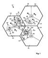
- Figure 1 shows a cellular network 11 having multiple macro cells 13.
- Each macro cell 13 has a macro base station 15 arranged for controlling the macro cell 13, in particular terminals 17 located within that macro cell 13 and registered ,with the macro base station 15 of that macro cell 13.
- a single macro base station 15 is assigned to three macro cells 13.
- only one macro cell 13 is assigned to a macro base station 15.
- the cellular network 11 has multiple pico cells 19, each of them having a pico base station 21.
- each pico base station 21 controls exactly one pico cell 19 and terminals 17 registered with the corresponding pico base station 21.
- a maximum transmission power of a radio signal transmitted by a pico base station 21 is less than a maximum transmission power of a radio signal sent by the macro base station 15. Consequently, the size of a pico cell 19, i.e., the coverage area of a pico cell, is less than the size of a macro cell 13.
- the pico cells 19 are overlapping with at least one macro cell 13.
- a pico base station 21 is preferably located within an area where a density of terminals 17 is comparatively high.
- At least a part of the terminals 17 located within a pico cell 19 may leave the macro cell 13 and register with the pico base station 21 of the pico cell 19. In this way, installing pico base stations 21 in areas with a high density of terminals 17 helps to improve a quality of service and/or a channel capacity experienced by users of the terminal 17 located in that area having a high terminal density.
- the cellular network 11 may be part of a Long Term Evolution (LTE) or Long Term Evolution advanced (LTE advanced) mobile communication system. Both LTE and LTE advanced are specified by the Third Generation Partnership project (3GPP). However, the present invention is not limited to LTE or LTE advanced. It may be applied in connection with different types of cellular networks or mobile communication systems, too.
- LTE Long Term Evolution
- LTE advanced Long Term Evolution advanced
- 3GPP Third Generation Partnership project
- the present invention is not limited to LTE or LTE advanced. It may be applied in connection with different types of cellular networks or mobile communication systems, too.
- each macro base station 15 comprises a first transceiver 23 having a first transmitter 25 and a first receiver 27.
- the first transmitter 25 and the first receiver 27 are coupled with a first antenna 29 such that the first transmitter 25 can transmit the radio signal to a terminal 17 and the first receiver 27 can receive a radio signal from a terminal 17.
- the macro base station 15 comprises a first transmit buffer 31 coupled with the first transmitter 25 and arranged for buffering data packets to be transmitted by the first transmitter 25.
- the macro base station 15 has a network interface circuitry 33 that is connected to an interconnection network 35 of the cellular network 11.
- the interconnection network 35 may be a fixed network or a wireless network.
- at least one pico base station 21 is a relay node connected by means of a radio link to a macro base station 15 functioning as a donor base station to which the relay node is assigned.
- the macro base station 15 has a first control circuitry 37 arranged for controlling the macro base station 15.
- the pico base station 21 has essentially the same configuration like the macro base station 15.
- the pico base station 21 also comprises the first transceiver 23, the transmit buffer 31, the network interface circuitry 33, and the first control circuitry 37.
- the first control circuitry 37 may comprise a scheduler for scheduling transmissions between the corresponding base station 15, 21 and the terminals 17 registered with that base station 15, 21.
- Both the macro base stations 15 as well as the pico base stations 21 are interconnected to each other by means of the interconnection network 35.
- Each terminal 17 comprises a second transceiver 39 having a second transmitter 41 and a second receiver 43.
- the second transmitter 41 is coupled to a second antenna 45 of the terminal 17 for transmitting a radio signal to a base station 15, 21.
- the second receiver 43 is coupled with the second antenna 45 for receiving a radio signal from a base station 15, 21.
- the terminal 17 further comprises a second transmit buffer 47 for storing data packets to be transmitted by the second transmitter 41.
- a second control circuitry 49 of the terminal 17 is arranged for controlling the terminal 17.
- Both the first control circuitry 37 and the second control circuitry 49 may comprise a processor such as a micro computer, in particular a microcontroller, programmed for controlling the base station 15, 21 or the terminal 17.
- the first control circuitry 37 may be arranged or programmed for executing a method for inter-cell interference coordination.
- the network 11 may comprise a central network element 51 connected to the interconnection network 35.
- the central network element 51 may comprise third control circuitry 52, preferably comprising a processor, arranged and/or programmed for executing a method for inter-cell interference coordination.
- the central network element 51 is omitted.
- the base station 15, 21 is also referred to as enhanced NodeB (eNodeB).
- the terminal is also referred to as User Equipment (UE).
- eNodeB enhanced NodeB
- UE User Equipment
- ICOIC inter-cell interference coordination
- radio transmission resources 53 comprise two channels 55. Each channel 55 occupies a separate frequency band B 1 and B 2 . In the shown embodiment, the channels 55 are directly adjacent, i.e., there is no gap between the two frequency bands B 1 and B 2 . In another embodiment, the channels 55 are not directly adjacent and there is a gap between the two frequency bands B 1 and B 2 .
- the channels 55 correspond to two portions of the radio transmission resources 53, the first frequency band B 1 corresponding to a first portion of the transmission resources and the second frequency band B 2 corresponding to a second portion of the transmission resources.
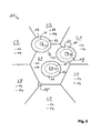
- the transmission resources 53 are assigned to the macro base stations 15 according to a macro cell resource assignment 57 shown in Figure 3 .
- the first portion of the transmission resource 53 i.e. the first frequency band B 1 is assigned to the macro cells 13. That is, the macro base stations 15 may transmit the radio signal using at least a part of the first frequency band B 1 with a maximum transmit power P f .
- the second frequency band B 2 is assigned to the macro cells 13, too.
- the macro base stations 15 limit the transmission power of the radio signal to a transmit power limit P red , i.e. , the macro base stations 15 transmit with a reduced transmission power.
- the transmission power that can be applied when transmitting using the first frequency band B 1 is not limited to the transmit power limit P red .
- both frequency bands B 1 , B 2 are assigned to the pico cell 19 as shown in a diagram of a pico cell resource assignment 59.
- the whole first frequency band B 1 is assigned to the pico cell 19.
- only a part of the first frequency band B 1 is assigned to the pico cell 19 (see hedged regions in the diagram of the pico cell resource assignment 59).
- FIG. 1 shows a coverage area A 1 of the pico cells 19 resulting if the macro base stations 15 transmit the radio signal using the second frequency band.B 2 with unlimited transmission power.
- the area A 2 corresponds to the coverage area of the pico cell 19 resulting when the transmission power of the macro base stations 15 is limited to the transmit power limit P red when transmitting using the second frequency band B 2 .
- the coverage area A 1 , A 2 correspond to the area in which the terminals 17 can receive control channel data transmitted by the corresponding pico base station 21.
- this control channel may correspond to the Physical Downlink Control Channel (PDCCH), the Physical Broadcast Channel (PBCH), the Physical Control Format Indicator Channel (PCFICH), the Physical Hybrid ARQ Indicator Channel (PHICH), or to another control channel.
- PDCCH Physical Downlink Control Channel
- PBCH Physical Broadcast Channel
- PCFICH Physical Control Format Indicator Channel
- PHICH Physical Hybrid ARQ Indicator Channel
- a third portion of the radio transmission resources 53 is assigned to the macro cells 13.
- the macro base stations 15 When transmitting using the third portion of the transmission resources 53 the macro base stations 15 must limit the transmission power to a further transmit power limit P m that is less than the maximum transmission power P f .
- the third portion is a sub-band F 1 , F 2 ,...,F R of the first frequency band B 1 .
- the first frequency band B 1 is subdivided into R sub-bands F 1 ,..., F R .
- each macro base station 15 is transmitting within a certain macro cell 13 in an different sub band F 1 ,...,F R with the transmission power limited to the further transmit power limit P m .
- the macro base station 15 of macro cell M 1 can communicate with a terminal 17 which is registered to M1 and located at a cell border between the cells M 1 and M 2 using the sub band F 4 in order to decrease in inter-cell interference between these two macro cells M 1 and M 2 .
- the macro base station 15 of macro cell M 2 can use the sub band F 3 in order to communicate with terminal 17 which is registered to macro cell M 2 and located at the border between the macro cells M 2 and M 2 . Partitioning the radio resources 53 into multiple third portions F 1 , ...F R (e.g.
- subbands F 1 , ...,F R subbands F 1 , ...,F R
- assigning to each macro cell 13 of a group of R macro cells 13 a different third portion and configuring or controlling the corresponding macro base stations 15 such that they limit the transmit power within the third portion F 1 , ..., F R assigned to them to the further transmit power limit P m is also referred to as "inverted reuse".
- the number of macro cells 13 and the number of different third portions is referred to as a reuse factor R.
- the third portion assigned to a certain macro cell 13 is also assigned to a pico cell 19 that is located within that macro cell 13.
- the pico base station 21 of that pico cell 19 may use this portion for communicating with terminals 17 located at a region at the edge of the pico cell 19.
- the pico cell P 1 is located within the macro cell, M 1 . Consequently, that pico cell P 1 uses not only the second frequency band B 2 , but also the sub band F 3 for communicating with terminals 17 located in a region at the edge of the pico cell 19, i.e., near a border of the coverage area A 2 .
- cross-carrier scheduling may be used.
- a control channel (e.g. a PDCCH) of the channel 55 relating to the second frequency band B 2 may signal to the terminals 17 that cross-carrier scheduling is applied.
- a maximum transmission power P pico of the radio signal transmitted by the pico base stations 21 does not vary depending on the frequency band B 1 , B 2 or subband F 1 , ..., F R on which the signal is transmitted. In another embodiment, the maximum transmission power P pico depends on the frequency band B 1 , B 2 or subband F 1 , ..., F R 55. For instance, the maximum transmission power P pico for the first band B 1 may be limited to a pico cell transmit power limit P pico , red being less than the maximum transmit power P pico for the second band B 2 .
- the pico base station 21 may schedule terminals 17 located near a border of the pico cell 19 preferably on the second band B 2 - Moreover, the pico base station 21 may schedule terminals 17 located in an inner region of the pico cell 21 on the first band B 1 . Furthermore, a macro base station 15 may schedule terminals 17 registered with a macro cell 13 controlled by this macro base station 15 and located at the border of the pico cell 19 preferably for transmission on the first band B 1 .
- the value of the transmit power limit P red is adapted depending on the distribution of data traffic relating to the terminals 17 and/or the special density of the terminals 17.
- At least one characteristic of communication traffic 60 related to at least one terminal 17 may be determined. For example, status information sb of the first transmit buffer 31 of a base station 15, 21 and/or status information st of the second transmit buffer 47 of at least one terminal 17 may be retrieved.
- the terminal 17 may report the status information st to the base station 15, 21 with which it is registered by transmitting a buffer status report (BSR).
- BSR buffer status report
- the base stations 15, 21 and the central network element 51 may exchange this information sb, st over the interconnection network 35.
- At least one parameter indicating the density of terminal 17 within a macro cell 13 or a pico cell 19 may be determined. For example, a number n m of terminals 17 registered with a macro cell 13 and/or a number n p of terminal 17 registered with a pico cell 19 may be determined.
- the base stations 15, 21 and the central network element 51 may exchange this parameters n m , n p .
- the method may determine the value of the transmit power limit P red depending on this characteristics sb, st, parameters n m , and/or n p .
- the partitioning of the transmission resources 53 is adapted depending on the characteristic of the communication traffic related to at least one terminal 17, e.g., depending on the buffer status information sb, st, and/or depending on the spatial distribution of the terminals 17, e.g. on a parameter indicating the density of the terminals such as the number n m , n P of terminals 17 located in a certain cell 13, 19.
- the transmit power limit P red and/or the partitioning of the radio resources 53 between the frequency band B 1 and B 2 may be optimised for maximizing a throughput for fair scheduling or guaranteed bit-rate scheduling in a group of macro cells 13 and pico cells 19 that are affected by inter-cell interference.
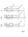
- the radio resources 53 comprise a single frequency channel 55 only. This channel 55 is subdivided into multiple sub bands F 1 ,...F N .
- the method provides the macro cell resource assignment 57 as indicated in the two diagrams depicted in Figure 4 , assigning a first portion (all sub bands F 1 , ...,F N except the sub band F 4 ) to the macro cells 13 and the second portion (the sub band F 4 ) to the macro cells 13.
- the macro base stations 15 are allowed to use at least a part of the first portion F 1 ,...,F 3 , F 5, ---,F N for sending a radio signal with the maximum transmission power P max .
- the macro cell base stations 15 must limit the transmission power of a radio signal transmitted using the second portion F 4 to the transmit power limit P red . Because all macro base stations 15 transmit with the limited transmission power when using the second portion F 4 the pico base stations 21 may use the second portion F 4 for communicating with terminals 17 located nearby a cell border of the corresponding pico cells 19.
- inverted reuse may be performed.
- a third portion of the radio resources 53 is allocated and the corresponding macro base stations 15 must limit the transmission power to the further transmit power limit P m when sending a radio signal using the third portion.
- Figure 4 shows the macro cell resource allocation 57 used for macro cell C 1 , ..., C 7 shown in Figure 5 .
- the second portion F 4 and the third portion F 3 of the transmission resources 53 that may be used with the limited transmission power only by a certain macro base station 15 are depicted.
- the three different macro cells resource assignments 57 shown in the three diagrams of Figure 4 are used for the macro cells C 1 ,...,C 7 depicted in Figure 5 .
- Each macro cell C 1 ,...,C 7 has the same second portion F 4 , whereas the third portion (one of F 1 , F 2 , F 3 ) of neighbouring macro cells is different in order to reduce inter-cell interference between neighbouring macro cells.
- the exemplary cellular network 11 shown in Figure 5 has three pico cells 19, one of them being completely embedded into the macro cell C 4 , another one overlapping with macro cells C 2 , C 3 , and C 4 and yet another one overlapping with macro cells C 1 and C 4 .
- a terminal 17 may receive signals from different macro cells C 1 .,...,C 7 and/or pico cells. All macro cells C 1 ,...,C 7 and all pico cells 19 have different cell identifiers (cell IDS).
- cell IDS cell identifiers
- a reference signal in a downlink frame measured by the terminals 17 can be associated to the different cells C 1 ,...,C 7 , 19. Signals being transmitted from different base stations 15, 21 can therefore distinguished by each terminal 17.
- the pico base stations 21 use the transmission resources 53 without particular restrictions.
- the pico base stations 21 may use a maximum transmission power for transmitting the radio signals using all sub bands F 1 ,...F N .
- the maximum transmission power of a pico cell 21 is typically less than the maximum transmission power P max of the macro cells C 1 ,...,C 7 .
- interference measurements are performed and additional restrictions regarding the usage of the transmission resources 53 by the pico base stations 21 are introduced depending on these measurements.
- the measurements may be carried out by the terminals 17 registered with the pico cells 19 and report it to their serving pico base stations 21. Introducing these additional restrictions further reduces inter-cell interference between the pico cells 19 and the macro cells C 1 ,...C 7 that they overlap.
- the measurements performed by the terminals may include pathloss measurements and interference measurements.
- a pico cell 19 is located completely within one macro cell, i.e., that pico cell 19 overlaps only one macro cell.
- Figure 5 shows a pico cell 19 that is located completely within the macro cell C 4 .
- Terminal 17 located within that pico cell 19 report measurements to their serving pico base station 21 that indicates that these terminals 19 see the macro cell C 4 as the strongest interfering cell.
- the pico base station 21 may determine based on the measurements performed by the terminal whether the terminal 17 is located in an inner region 61 of the pico cell 19 or within a border region 62 of that micro cell 21.
- terminals 21 located in the border region 62 are scheduled on the sub bands F 1 and/or F 4 because these sub bands F 1 F 4 are used with the limited power in the macro cell C 4 .
- the sub bands F 1 and F 4 are not used at all by the macro cell C 4 , i.e., the transmit power limit P red is set to zero.
- the terminal 17 located in the inner region 61 of the pico cell may use all frequency sub-bands F 1 ,..,F N .
- Scheduling the terminals 17 located in the border region 62 of the pico cell 19 on the sub-bands F 1 and F 4 induces low interference with the surrounding macro cell C 4 . Under ideal circumstances, the interference can be completely avoided.
- the pico cell 19 is located at a border between multiple macro cells.
- This pico cell 19 overlaps these two macro cells C 1 , C 4 .
- Terminals 17 located in the border region 62 of that pico cell 19 are scheduled on sub-band F 4 because the sub-band is used with limited transmit power P red by the macro base stations 15 of macro cells. C 1 and C 4 .
- the transmit power limit P red is zero and the macro cells C 1 and C 4 do not use the sub-band F 4 at all.
- Terminals 17 located in the inner region 62 of that pico cell 19 may be scheduled on all frequency sub-bands with exception of sub-bands F 1 and F 2 which are used by the macro cells C 1 and C 4 for communicating with terminal 17 located on the border between them.
- the terminals located in a border region 61 of a pico cell 19 are scheduled on those sub-bands that belong to the third portion of sub-bands of the macro cells that are overlapped by the pico cell 19.
- the pico base station 21 may schedule terminals 17 located in the border region 62 of the corresponding pico cell 19 and within a certain macro cell on the sub-band that belongs to the third portion of that macro cell.
- a terminal 17 located in the border region 62 of the pico cell 19 on the right hand side of Figure 5 and within the macro cell C 1 may be scheduled by the pico base station 21 of that pico cell on the sub-band F 2 which corresponds to the third portion of radio resources 53 assigned to that macro cell C 1 .
- the pico base station 21 may schedule the terminal 17 on sub-band F 1 because the sub-band F 1 corresponds to the third portion of radio resources 53 assigned to the macro cell C 4 . Furthermore, the pico base station 21 may schedule the terminal 17 on the sub-band F 4 because all macro base stations 15 use this sub-band corresponding to the second portion of the radio resources 53 with the transmit power limited to the transmit power limit P red .
- the restrictions and limits regarding the transmit power of the sub-bands F 1 ,...,F N may be configured statically or semi-statically.
- the first portion of radio transmission resources of the cellular network and the second portion of said transmission resources are assigned statically to each of the multiple macro base stations for transmitting a radio signal using the first portion and the second portion of the transmission resources.
- Each of the multiple macro base stations is arranged for limiting a maximum transmission power of the radio signal to be transmitted using the second portion to the transmit power limit P red less than the maximum transmit power P f of the signal to be transmitted using the first portion.
- the above-described method is executed by a network element of the cellular network 11, such as a base station 15, 21 or the central network element 51.
- the method may be executed by one of these network elements 15, 21, 51 or distributed on multiple network elements 15, 21, 51.
- information about resource assignments 57, 59 may be exchanged between the network elements 15, 21, 51 over the interconnection network 35.
- the X 2 interface of LTE may be applied, which allows for information exchange between different base stations 15, 21.
- the base stations 15, 21 and the central network element 51 may exchange Relative Narrowband Transmit Power (RNTP) messages that indicate physical resource blocks (PRB) that are guaranteed to have a power allocation below a power threshold, e.g., the transmit power limit P red or the further transmit power limit P m .
- RNTP Relative Narrowband Transmit Power
- the method described above allows for reducing interference between a pico cell 19 overlapping one or more macro cells 13 by reserving a portion of the transmission resources 53 that may be used by the pico base stations 21 to communicate with terminals 17 located within the border region 61 of the corresponding pico cells 19.
- the macro base stations 15 transmit on this portion of the radio transmission resources 53 with a transmission power limited to the transmission power limit P red .
- the macro base stations 15 do not transmit on this portion of the radio transmission resources 53 not at all.
- a inverted reuse scheme is used for coordinating interference between neighbouring macro cells and for further reducing the interference between the pico cells 29 and/or macro cells 13.
- the method allows for increasing the size of a pico cell 19 without increasing a maximum transmit power of this pico cell 19.
Abstract
- assigning (57) a first portion (B1) of radio transmission resources (53) of the cellular network (11) and a second portion (B2) of said transmission resources (53) to each of said multiple macro base stations (15) for transmitting a radio signal using the first portion (B1) and the second portion (B2) of said transmission resources (53) and
-limiting a maximum transmission power of the radio signal to be transmitted using the second portion (B2) to a transmit power limit (Pred) less than a maximum transmit power (Pf) of the signal to be transmitted using the first portion (B1).
- assigning (59) the second portion (B2) of said transmission resources (53) to the pico base station (21) for transmitting the radio signal using the second portion (B2) of said transmission resources.
Description
- The present invention refers to a method for inter-cell interference coordination (ICIC) in an cellular communication network comprising multiple macro base stations controlling a macro cell of the cellular network and at least one pico base station (also referred to as low power base station) controlling a pico cell (also referred to as low power cell) of the cellular network, said pico cell being located at least partially within at least one macro cell. Furthermore, the present invention refers to a network element of such a cellular communication network. Moreover, the present invention refers to a cellular communication network comprising multiple base stations controlling a macro cell of the cellular network and at least one pico base station controlling a pico cell of the cellular network, said pico cell being located at least partially within at least one macro cell.
- Inter-cell interference coordination (ICIC) is known in the art. In particular, a base station (a so-called eNodeB) of the long term evolution (LTE) cellular radio access network and its successor LTE advanced may coordinate the allocation of radio transmission resources with neighbouring base stations in order to reduce inter-cell interference and to improve an overall spectral efficiency and/or an overall throughput of the radio access network.
- A known approach of inter-cell interference coordination is fractional frequency reuse. According to fractional frequency reuse, a base station of a macro cell uses a first portion of radio transmission resources for transmitting a radio signal, a transmission power of which can reach a maximum transmit power. By using the first portion of radio transmission resources the base station can reach terminals of the cellular communication networks located at an edge of the cell controlled by the base station. The base station uses another portion of the transmission resources with a limited transmission power in order to reduce inter-cell interference with neighbouring macro cells. A base station of the neighbouring macro cell may use the further portion of the transmission resources for communicating with a terminal located at a cell edge of said neighbouring macro cell. Therefore, the base station may use all portions of the transmission resources for terminals located in an inner region of the cell and use only a part of the transmission resources for terminals located in a cell edge region of the cell.
- The known approaches for inter-cell interference coordination allow to reduce the interference of neighbouring macro cells. However, the known approaches of inter-cell interference coordination do not allow for control the interference between a macro cell and a pico cell located within the macro cell.
- The object of the present invention is to provide a method, a network element, and a cellular communication network that improve a throughput of cells of a cellular communication network and/or the spectral efficiency of transmission resources of the cellular network.
- As a first solution of this object, a method for inter-cell interference coordination in a cellular communication network is suggested, the network comprising multiple macro base stations controlling at least one of multiple macro cells of the cellular network and at least one pico base station controlling at least one pico cell of the cellular network, said pico cell being located at least partially within at least one macro cell, said method comprising: assigning a first portion of radio transmission resources of the cellular network and a second portion of said transmission resources to each of said multiple macro base stations for transmitting a radio signal using the first portion and the second portion of said transmission resources and limiting a maximum transmission power of the radio signal to be transmitted using the second portion to a transmit power limit, the transmit power limit being less than a maximum transmit power of the signal to be transmitted using the first portion, wherein the method further comprises assigning the second portion of said transmission resources to the pico base station for transmitting the radio signal using the second portion of said transmission resources. In an embodiment, at least a part of the first portion is assigned to the pico base station, too.
- In other words, a base station of a macro cell uses a transmission power that is limited to said transmit power limit when transmitting a radio signal using the second portion of the transmission resources so that a pico base station of the pico cell may use the second portion for communicating with terminals registered with the pico base station with low interference. Preferably, the pico base stations uses the second portion of transmission resources for communicating with terminals located within an border region of the pico cell, i.e., for communicating with terminals located rather far away from the pico cell base station. Limiting the maximum transmission power of the radio signal transmitted by the macro base stations using the second portion allows not only for reducing an interference between the macro cells and the pico cells embedded therein but also increases a cell size of the pico cell.
- The radio resources may be partitioned into the first portion and the second portion according to time. Time may be subdivided into multiple consecutive time units. A first subset of these time units may correspond to the first portion, whereas a second subset of the time units may correspond to the second portion. In a preferred embodiment, the radio transmission resources are partitioned according to frequency, i.e., the first portion corresponds to a first frequency range and/or the second portion corresponds to a second frequency range of the transmission resources.
- In LTE, transmission resources are subdivided in the frequency domain into multiple consecutive physical resource blocks (PRB). In time domain, the transmission resources are subdivided into multiple consecutive subframes of a radio frame. Accordingly, when using the method in connection with LTE, the first portion may correspond to a set of one or more physical resource blocks and/or the second portion may correspond to a second set of one or more physical resource blocks, the first and the second set being disjunctive. In an embodiment, the first portion and/or the second portion may correspond to a set of consecutive physical resource blocks. It should be noted that the present invention may be applied in connection with LTE but can also be applied in connection with a cellular communication network of a different type.
- In an embodiment, the cellular network has a group of multiple pico base stations and the method comprises assigning the second portion of the transmission resources to all pico base stations of said group. Thus, all pico base stations of that said group may transmit a radio signal within the second portion of the transmission resources. In other words, all pico base stations of the group, preferably all pico base stations of the cellular network, use the identical second portion of the transmission resources in order to communicate with at least one terminal registered with that pico base station.
- In an embodiment, the transmit power limit is a predefined static value that can be changed manually only. In another embodiment, the transmit power limit is determined semi-statically or dynamically depending on an operating status of the cellular communication network, preferably the macro base stations, the pico base station, and/or the terminal.
- In particular, in a preferred embodiment, the method comprises determining at least one characteristic of communication traffic related to at least one terminal registered with a macro base station and/or the pico base station and determining the transmit power limit depending on said characteristic. Adapting the transmit power limit to the traffic allows for adaptively changing a size, i.e., a coverage area, of the pico cell.
- In an embodiment, determining the at least one characteristic comprises retrieving buffer status information of a transmit buffer of a macro base station, a pico base station and/or the terminal. Information about the transmit buffer allows from estimating the amount of data to be transferred between the macro base station or the pico base station and the terminal. For instance, if the terminal is registered with the pico base station and is communicating with the pico base stations using the second portion of the transmission resources and if the transmit buffer has many data packets stored to be transmitted over the transmission resources then the transmit power level may be decreased in order to reduce interference between the pico cell and the macro cell in which the pico cell is embedded so that the throughput for the data communication between the pico base station and the terminal can be improved.
- Preferably, the method comprises determining the transmit power limit depending on a parameter indicating a density of terminals within a macro cell and/or a pico cell, preferably depending on a number of terminals registered with a certain macro base station or pico base station. For instance, a number of terminals registered with the pico base station can be determined. If the number of terminals registered with the pico base station is low then the transmit power limit may be decreased in the macro base station in order to increase the coverage area.of the corresponding pico cell so that additional terminals can register with the pico base station.
- In an embodiment, the method comprises assigning the first portion of the transmission resources to the pico cell and limiting the transmission power of a radio signal to be transmitted by the pico base station using the first portion to a pico cell transmit power limit, the pico cell transmit power limit being less than a maximum transmit power of the signal to be transmitted within the pico cell by the pico base station.
- Preferably, the method comprises scheduling at least some terminals registered with the pico base station and located at a border region of the pico cell for transmissions using the second portion of the transmission resources and/or scheduling at least some terminals registered with a macro base station and located at the border region of the pico cell for transmissions using the first portion of the transmission resources and/or scheduling at least some terminals registered with a macro base station and located outside of any border region of a pico cell for transmission using the second portion of the transmission resources. Said scheduling may be performed by a scheduler of a macro base station and/or a scheduler of the pico base station.
- According to an embodiment, the transmit power limit is determined separately for each macro base station. Determining separate values of the transmit power limit for the individual macro base stations allows for a fine-grained inter-cell interference coordination. In another embodiment, the transmit power limit is determined as a single value for multiple macro base stations. Defining a single value simplifies the implementation of the method.
- In an embodiment, the partitioning of the radio transmission resources into the first portion and the second portion is static. In another embodiment, the first portion and/or the second portion is determined depending on said characteristic of the traffic related to at least one terminal and/or said parameter indicating the density of terminals. That is, the first portion and/or the second portion may be determined e.g. semi-statically depending on the operating status of the cellular network.
- In an embodiment, the transmission resources comprise multiple channels, each of them occupying a separate frequency band, and wherein the second portion of the radio resources corresponds to one of said multiple channels.
- In another embodiment, the transmission resources comprise a single channel subdivided into multiple sub-bands, the first portion and/or the second portion corresponding to a set of sub-bands. Preferably, the first portion and/or the second portion corresponds to a set of multiple consecutive sub-bands. These sub-bands may be arranged consecutively in the frequency domain. In an embodiment, a multi carrier modulation scheme such as orthogonal frequency division modulation (OFDM) is applied. A channel may correspond to a single OFDM carrier. A sub-band may correspond to multiple consecutive subcarriers of the OFDM carrier. In LTE, twelve consecutive subcarriers correspond to a Physical Resource Block (PRB). In an embodiment, a sub-band corresponds to one PRB or multiple consecutive PRBs.
- In an embodiment, the method comprises assigning a third portion of said radio transmission resources, preferably a third frequency range of the transmission resources, to at least one macro base station for transmitting the radio signal using the third portion and limiting a maximum transmission power of the radio signal to be transmitted using the third portion to a further transmit power limit being less than a maximum transmit power of the signal to be transmitted using the first portion. The third portion of the radio transmission resources can be used by a neighbouring macro base station for communicating with terminals located at a cell border between neighbouring macro cells. As a consequence, not only interference between the pico cell and the macro cells is coordinated but also interference between a neighbouring macro cells is coordinated. Thus, intra-cell-interference is further reduced and spectral efficiency and/or the overall throughput of the cellular network is further improved.
- Another solution of the above mentioned object consists in a network element of a cellular communication network comprising multiple macro base stations controlling at least one of multiple macro cells of the cellular network and at least one pico base station controlling at least one pico cell of the cellular network, said pico cell being located at least partially within at least one macro cell, said network element comprising control circuitry for inter-cell interference coordination arranged for: assigning a first portion of radio transmission resources of the cellular network and a second portion of said transmission resources to each of said multiple macro base stations for transmitting a radio signal using the first portion and the second portion of said transmission resources and limiting a maximum transmission power of the radio signal to be transmitted using the second portion to a transmit power limit being less than a maximum transmit power of the signal to be transmitted using the first portion, wherein said control circuitry is arranged for assigning the second portion of said transmission resources to the pico base station for transmitting the radio signal using the second portion of said transmission resources. This network element as the above-mentioned advantages of the method described above.
- Preferably, the control circuitry is arranged for executing a method according to the present invention, embodiments of which are described above. In an embodiment, the control circuitry comprises a processor programmed for executing a method according to the present invention.
- In an embodiment, the network element is a macro base station of the cellular network or a pico base station of the cellular network.
- A further solution of the above-mentioned object consists in a cellular communication network comprising multiple macro base stations controlling at least one of multiple macro cells of the cellular network and at least one pico base station controlling at least one pico cell of the cellular network, said pico cell being located at least partially within at least one macro cell, said network being arranged for: assigning a first portion of radio transmission resources of the cellular network and a second portion of said transmission resources to each of said multiple macro base stations for transmitting a radio signal using the first portion and the second portion of said transmission resources and limiting a maximum transmission power of the radio signal to be transmitted using the second portion to a transmit power limit being less than a maximum transmit power of the signal to be transmitted using the first portion, wherein the network is arranged for executing a method according to one of
claims 1 to 11, embodiments of which are described above. - This cellular communication network has the above-named advantages of the above described method and network element.
- Preferred embodiments and further advantages of the present invention are shown in the figures and described in detail hereinafter.
- Figure 1
- shows a cellular communication network;
- Figure 2
- shows network elements of the cellular network shown in
Figure 1 ; - Figure 3
- shows diagrams of radio transmissions resource allocations;
- Figure 4
- shows diagrams of radio transmission resource allocations similar to
Figure 3 according to a different embodiment; and - Figure 5
- shows a further cellular network.
- The description and drawings merely illustrate the principles of the invention. It will thus be appreciated that those skilled in the art will be able to devise various arrangements that, although not explicitly described or shown herein, embody the principles of the invention and are included within its spirit and scope. Furthermore, all examples recited herein are principally intended expressly to be only for pedagogical purposes to aid the reader in understanding the principles of the invention and the concepts contributed by the inventors to furthering the art, and are to be construed as being _ without limitation to such specifically recited examples and conditions. Moreover, all statements herein reciting principles, aspects, and embodiments of the invention, as well as specific examples thereof, are intended to encompass equivalents thereof.
-
Figure 1 shows acellular network 11 having multiplemacro cells 13. Eachmacro cell 13 has amacro base station 15 arranged for controlling themacro cell 13, inparticular terminals 17 located within thatmacro cell 13 and registered ,with themacro base station 15 of thatmacro cell 13. In the shown embodiment a singlemacro base station 15 is assigned to threemacro cells 13. In another embodiment, only onemacro cell 13 is assigned to amacro base station 15. - Furthermore, the
cellular network 11 hasmultiple pico cells 19, each of them having apico base station 21. In the shown exemplary embodiment, eachpico base station 21 controls exactly onepico cell 19 andterminals 17 registered with the correspondingpico base station 21. A maximum transmission power of a radio signal transmitted by apico base station 21 is less than a maximum transmission power of a radio signal sent by themacro base station 15. Consequently, the size of apico cell 19, i.e., the coverage area of a pico cell, is less than the size of amacro cell 13. Thepico cells 19 are overlapping with at least onemacro cell 13. Apico base station 21 is preferably located within an area where a density ofterminals 17 is comparatively high. At least a part of theterminals 17 located within apico cell 19 may leave themacro cell 13 and register with thepico base station 21 of thepico cell 19. In this way, installingpico base stations 21 in areas with a high density ofterminals 17 helps to improve a quality of service and/or a channel capacity experienced by users of the terminal 17 located in that area having a high terminal density. - The
cellular network 11 may be part of a Long Term Evolution (LTE) or Long Term Evolution advanced (LTE advanced) mobile communication system. Both LTE and LTE advanced are specified by the Third Generation Partnership project (3GPP). However, the present invention is not limited to LTE or LTE advanced. It may be applied in connection with different types of cellular networks or mobile communication systems, too. - As shown in
Figure 2 , eachmacro base station 15 comprises afirst transceiver 23 having afirst transmitter 25 and afirst receiver 27. Thefirst transmitter 25 and thefirst receiver 27 are coupled with afirst antenna 29 such that thefirst transmitter 25 can transmit the radio signal to a terminal 17 and thefirst receiver 27 can receive a radio signal from a terminal 17. Themacro base station 15 comprises a first transmitbuffer 31 coupled with thefirst transmitter 25 and arranged for buffering data packets to be transmitted by thefirst transmitter 25. Moreover, themacro base station 15 has anetwork interface circuitry 33 that is connected to aninterconnection network 35 of thecellular network 11. Theinterconnection network 35 may be a fixed network or a wireless network. In-an embodiment, at least onepico base station 21 is a relay node connected by means of a radio link to amacro base station 15 functioning as a donor base station to which the relay node is assigned. - Furthermore, the
macro base station 15 has afirst control circuitry 37 arranged for controlling themacro base station 15. Thepico base station 21 has essentially the same configuration like themacro base station 15. In particular, thepico base station 21 also comprises thefirst transceiver 23, the transmitbuffer 31, thenetwork interface circuitry 33, and thefirst control circuitry 37. Thefirst control circuitry 37 may comprise a scheduler for scheduling transmissions between thecorresponding base station terminals 17 registered with thatbase station macro base stations 15 as well as thepico base stations 21 are interconnected to each other by means of theinterconnection network 35. - Each terminal 17 comprises a
second transceiver 39 having asecond transmitter 41 and asecond receiver 43. Thesecond transmitter 41 is coupled to asecond antenna 45 of the terminal 17 for transmitting a radio signal to abase station second receiver 43 is coupled with thesecond antenna 45 for receiving a radio signal from abase station buffer 47 for storing data packets to be transmitted by thesecond transmitter 41. Asecond control circuitry 49 of the terminal 17 is arranged for controlling the terminal 17. Both thefirst control circuitry 37 and thesecond control circuitry 49 may comprise a processor such as a micro computer, in particular a microcontroller, programmed for controlling thebase station first control circuitry 37 may be arranged or programmed for executing a method for inter-cell interference coordination. - In an embodiment, the
network 11 may comprise acentral network element 51 connected to theinterconnection network 35. Thecentral network element 51 may comprisethird control circuitry 52, preferably comprising a processor, arranged and/or programmed for executing a method for inter-cell interference coordination. In another embodiments, thecentral network element 51 is omitted. - In LTE or LTE advanced, the
base station - In the following, a method for inter-cell interference coordination (ICOIC) is described in more detail. This method not only aims at coordinating the interference between a
macro cell 13 and apico cell 19 that is overlapped by thismacro cell 13 but also aims at coordinating the interference between neighbouringmacro cells 13. - In one embodiment, as shown in
Figure 3 ,radio transmission resources 53 comprise twochannels 55. Eachchannel 55 occupies a separate frequency band B1 and B2. In the shown embodiment, thechannels 55 are directly adjacent, i.e., there is no gap between the two frequency bands B1 and B2. In another embodiment, thechannels 55 are not directly adjacent and there is a gap between the two frequency bands B1 and B2. Thechannels 55 correspond to two portions of theradio transmission resources 53, the first frequency band B1 corresponding to a first portion of the transmission resources and the second frequency band B2 corresponding to a second portion of the transmission resources. - According to the method, the
transmission resources 53 are assigned to themacro base stations 15 according to a macrocell resource assignment 57 shown inFigure 3 . The first portion of thetransmission resource 53, i.e. the first frequency band B1 is assigned to themacro cells 13. That is, themacro base stations 15 may transmit the radio signal using at least a part of the first frequency band B1 with a maximum transmit power Pf. The second frequency band B2 is assigned to themacro cells 13, too. However, when using the second frequency band B2, themacro base stations 15, limit the transmission power of the radio signal to a transmit power limit Pred, i.e. , themacro base stations 15 transmit with a reduced transmission power. However, the transmission power that can be applied when transmitting using the first frequency band B1 is not limited to the transmit power limit Pred. - According to the method, both frequency bands B1, B2 are assigned to the
pico cell 19 as shown in a diagram of a picocell resource assignment 59. In an embodiment, the whole first frequency band B1 is assigned to thepico cell 19. In another embodiment, only a part of the first frequency band B1 is assigned to the pico cell 19 (see hedged regions in the diagram of the pico cell resource assignment 59). - Limiting the transmission power of the
macro base stations 15 to the transmit power limit Pred has the effect that the coverage area of thepico cells 19 increases (so-called "food print increase").Figure 1 shows a coverage area A1 of thepico cells 19 resulting if themacro base stations 15 transmit the radio signal using the second frequency band.B2 with unlimited transmission power. The area A2 corresponds to the coverage area of thepico cell 19 resulting when the transmission power of themacro base stations 15 is limited to the transmit power limit Pred when transmitting using the second frequency band B2. The coverage area A1, A2 correspond to the area in which theterminals 17 can receive control channel data transmitted by the correspondingpico base station 21. In LTE, this control channel may correspond to the Physical Downlink Control Channel (PDCCH), the Physical Broadcast Channel (PBCH), the Physical Control Format Indicator Channel (PCFICH), the Physical Hybrid ARQ Indicator Channel (PHICH), or to another control channel. - In order to coordinate interference between neighbouring macro cells 13 a third portion of the
radio transmission resources 53 is assigned to themacro cells 13. When transmitting using the third portion of thetransmission resources 53 themacro base stations 15 must limit the transmission power to a further transmit power limit Pm that is less than the maximum transmission power Pf. In the shown embodiment, the third portion is a sub-band F1, F2,...,FR of the first frequency band B1. In general, the first frequency band B1 is subdivided into R sub-bands F1,..., FR. To eachmacro cell 13 and the corresponding macro base station 15 a single sub band F1,..., FR is assigned. As a consequence, eachmacro base station 15 is transmitting within a certainmacro cell 13 in an different sub band F1,...,FR with the transmission power limited to the further transmit power limit Pm. - Assuming that the cells denoted by M1 and M2 are neighbouring
macro cells 13, themacro base station 15 of macro cell M1 can communicate with a terminal 17 which is registered to M1 and located at a cell border between the cells M1 and M2 using the sub band F4 in order to decrease in inter-cell interference between these two macro cells M1 and M2. Accordingly, themacro base station 15 of macro cell M2 can use the sub band F3 in order to communicate with terminal 17 which is registered to macro cell M2 and located at the border between the macro cells M2 and M2. Partitioning theradio resources 53 into multiple third portions F1, ...FR (e.g. subbands F1, ...,FR) and assigning to eachmacro cell 13 of a group of R macro cells 13 a different third portion and configuring or controlling the correspondingmacro base stations 15 such that they limit the transmit power within the third portion F1, ..., FR assigned to them to the further transmit power limit Pm is also referred to as "inverted reuse". The number ofmacro cells 13 and the number of different third portions is referred to as a reuse factor R. - In an embodiment, the third portion assigned to a certain
macro cell 13 is also assigned to apico cell 19 that is located within thatmacro cell 13. Thepico base station 21 of thatpico cell 19 may use this portion for communicating withterminals 17 located at a region at the edge of thepico cell 19. In the example shown inFigure 3 , the pico cell P1 is located within the macro cell, M1. Consequently, that pico cell P1 uses not only the second frequency band B2, but also the sub band F3 for communicating withterminals 17 located in a region at the edge of thepico cell 19, i.e., near a border of the coverage area A2. In order to efficiently assign the transmission resources of the second frequency band B2 and the sub band F3, i.e., the third portion assigned to themacro cell 13 in which thepico cell 19 is embedded, cross-carrier scheduling may be used. A control channel (e.g. a PDCCH) of thechannel 55 relating to the second frequency band B2 may signal to theterminals 17 that cross-carrier scheduling is applied. - In an embodiment, a maximum transmission power Ppico of the radio signal transmitted by the
pico base stations 21 does not vary depending on the frequency band B1, B2 or subband F1, ..., FR on which the signal is transmitted. In another embodiment, the maximum transmission power Ppico depends on the frequency band B1, B2 or subband F1, ...,F R 55. For instance, the maximum transmission power Ppico for the first band B1 may be limited to a pico cell transmit power limit Ppico,red being less than the maximum transmit power Ppico for the second band B2. Thepico base station 21 may scheduleterminals 17 located near a border of thepico cell 19 preferably on the second band B2- Moreover, thepico base station 21 may scheduleterminals 17 located in an inner region of thepico cell 21 on the first band B1. Furthermore, amacro base station 15 may scheduleterminals 17 registered with amacro cell 13 controlled by thismacro base station 15 and located at the border of thepico cell 19 preferably for transmission on the first band B1. - In the shown embodiment, the value of the transmit power limit Pred is adapted depending on the distribution of data traffic relating to the
terminals 17 and/or the special density of theterminals 17. - To this end, at least one characteristic of
communication traffic 60 related to at least one terminal 17 (i.e. received or transmitted by that terminal 17) may be determined. For example, status information sb of the first transmitbuffer 31 of abase station buffer 47 of at least oneterminal 17 may be retrieved. The terminal 17 may report the status information st to thebase station base stations central network element 51 may exchange this information sb, st over theinterconnection network 35. - Furthermore, according to the method, at least one parameter indicating the density of
terminal 17 within amacro cell 13 or apico cell 19 may be determined. For example, a number nm ofterminals 17 registered with amacro cell 13 and/or a number np of terminal 17 registered with apico cell 19 may be determined. Thebase stations central network element 51 may exchange this parameters nm, np. After having acquired the characteristics sb, st of the traffic related to theindividual terminal 17 and the parameters nm, np indicating the density ofterminal 17, the method may determine the value of the transmit power limit Pred depending on this characteristics sb, st, parameters nm, and/or np. - In an embodiment, the partitioning of the
transmission resources 53 is adapted depending on the characteristic of the communication traffic related to at least oneterminal 17, e.g., depending on the buffer status information sb, st, and/or depending on the spatial distribution of theterminals 17, e.g. on a parameter indicating the density of the terminals such as the number nm, nP ofterminals 17 located in acertain cell - The transmit power limit Pred and/or the partitioning of the
radio resources 53 between the frequency band B1 and B2 may be optimised for maximizing a throughput for fair scheduling or guaranteed bit-rate scheduling in a group ofmacro cells 13 andpico cells 19 that are affected by inter-cell interference. - According to another embodiment of the method according to the present invention, the
radio resources 53 comprise asingle frequency channel 55 only. Thischannel 55 is subdivided into multiple sub bands F1,...FN. The method provides the macrocell resource assignment 57 as indicated in the two diagrams depicted inFigure 4 , assigning a first portion (all sub bands F1, ...,FN except the sub band F4) to themacro cells 13 and the second portion (the sub band F4) to themacro cells 13. Themacro base stations 15 are allowed to use at least a part of the first portion F1,...,F3, F5,---,FN for sending a radio signal with the maximum transmission power Pmax. However, the macrocell base stations 15 must limit the transmission power of a radio signal transmitted using the second portion F4 to the transmit power limit Pred. Because allmacro base stations 15 transmit with the limited transmission power when using the second portion F4 thepico base stations 21 may use the second portion F4 for communicating withterminals 17 located nearby a cell border of thecorresponding pico cells 19. - Moreover, inverted reuse may be performed. For each macro cell 13 a third portion of the
radio resources 53 is allocated and the correspondingmacro base stations 15 must limit the transmission power to the further transmit power limit Pm when sending a radio signal using the third portion. In the shown embodiment the further transmit power limit is equal to the transmit power limit, Pred = Pm. In another embodiment these value differ from each other, Pred≠Pm. -
Figure 4 shows the macrocell resource allocation 57 used for macro cell C1, ..., C7 shown inFigure 5 . InFigure 4 the second portion F4 and the third portion F3 of thetransmission resources 53 that may be used with the limited transmission power only by a certainmacro base station 15 are depicted. The three different macrocells resource assignments 57 shown in the three diagrams ofFigure 4 are used for the macro cells C1,...,C7 depicted inFigure 5 . Each macro cell C1,...,C7 has the same second portion F4, whereas the third portion (one of F1, F2, F3) of neighbouring macro cells is different in order to reduce inter-cell interference between neighbouring macro cells. - The exemplary
cellular network 11 shown inFigure 5 has threepico cells 19, one of them being completely embedded into the macro cell C4, another one overlapping with macro cells C2, C3, and C4 and yet another one overlapping with macro cells C1 and C4. A terminal 17 may receive signals from different macro cells C1.,...,C7 and/or pico cells. All macro cells C1,...,C7 and allpico cells 19 have different cell identifiers (cell IDS). Thus, a reference signal in a downlink frame measured by theterminals 17 can be associated to the different cells C1,...,C7, 19. Signals being transmitted fromdifferent base stations - In an embodiment, the
pico base stations 21 use thetransmission resources 53 without particular restrictions. For example, in the embodiment shown inFigures 4 and5 thepico base stations 21 may use a maximum transmission power for transmitting the radio signals using all sub bands F1,...FN. However, the maximum transmission power of apico cell 21 is typically less than the maximum transmission power Pmax of the macro cells C1,...,C7. - In another embodiment, interference measurements are performed and additional restrictions regarding the usage of the
transmission resources 53 by thepico base stations 21 are introduced depending on these measurements. The measurements may be carried out by theterminals 17 registered with thepico cells 19 and report it to their servingpico base stations 21. Introducing these additional restrictions further reduces inter-cell interference between thepico cells 19 and the macro cells C1,...C7 that they overlap. The measurements performed by the terminals may include pathloss measurements and interference measurements. - When deciding on introducing additional restrictions related to the
pico cells 19, two exemplary cases can be distinguished. - In a first case, a
pico cell 19 is located completely within one macro cell, i.e., thatpico cell 19 overlaps only one macro cell. For example,Figure 5 shows apico cell 19 that is located completely within the macro cell C4. Terminal 17 located within thatpico cell 19 report measurements to their servingpico base station 21 that indicates that theseterminals 19 see the macro cell C4 as the strongest interfering cell. In addition, thepico base station 21 may determine based on the measurements performed by the terminal whether the terminal 17 is located in aninner region 61 of thepico cell 19 or within aborder region 62 of thatmicro cell 21. According to one embodiment,terminals 21 located in theborder region 62 are scheduled on the sub bands F1 and/or F4 because these sub bands F1 F4 are used with the limited power in the macro cell C4 . In another embodiment, the sub bands F1 and F4 are not used at all by the macro cell C4, i.e., the transmit power limit Pred is set to zero. Preferably, the terminal 17 located in theinner region 61 of the pico cell may use all frequency sub-bands F1,..,FN. - Scheduling the
terminals 17 located in theborder region 62 of thepico cell 19 on the sub-bands F1 and F4 induces low interference with the surrounding macro cell C4. Under ideal circumstances, the interference can be completely avoided. - In a second case, the
pico cell 19 is located at a border between multiple macro cells. For example inFigure 5 , there is onepico cell 19 that is located on the border between the macro cells C1 and C4. Thispico cell 19 overlaps these two macro cells C1, C4. Terminals 17 located in theborder region 62 of thatpico cell 19 are scheduled on sub-band F4 because the sub-band is used with limited transmit power Pred by themacro base stations 15 of macro cells. C1 and C4. In another embodiment, the transmit power limit Pred is zero and the macro cells C1 and C4 do not use the sub-band F4 at all.Terminals 17 located in theinner region 62 of thatpico cell 19 may be scheduled on all frequency sub-bands with exception of sub-bands F1 and F2 which are used by the macro cells C1 and C4 for communicating with terminal 17 located on the border between them. - In another embodiment, the terminals located in a
border region 61 of apico cell 19 are scheduled on those sub-bands that belong to the third portion of sub-bands of the macro cells that are overlapped by thepico cell 19. Moreover, thepico base station 21 may scheduleterminals 17 located in theborder region 62 of thecorresponding pico cell 19 and within a certain macro cell on the sub-band that belongs to the third portion of that macro cell. For example, a terminal 17 located in theborder region 62 of thepico cell 19 on the right hand side ofFigure 5 and within the macro cell C1 may be scheduled by thepico base station 21 of that pico cell on the sub-band F2 which corresponds to the third portion ofradio resources 53 assigned to that macro cell C1. - If that terminal 17 moves to the macro cell C4 without leaving the
border region 62 of the pico cell 19 (and staying registered with the pico station 21) then thepico base station 21 may schedule the terminal 17 on sub-band F1 because the sub-band F1 corresponds to the third portion ofradio resources 53 assigned to the macro cell C4. Furthermore, thepico base station 21 may schedule the terminal 17 on the sub-band F4 because allmacro base stations 15 use this sub-band corresponding to the second portion of theradio resources 53 with the transmit power limited to the transmit power limit Pred. - The restrictions and limits regarding the transmit power of the sub-bands F1,...,FN may be configured statically or semi-statically. In an embodiment according to which these restriction and limits are configured statically, the first portion of radio transmission resources of the cellular network and the second portion of said transmission resources are assigned statically to each of the multiple macro base stations for transmitting a radio signal using the first portion and the second portion of the transmission resources. Each of the multiple macro base stations is arranged for limiting a maximum transmission power of the radio signal to be transmitted using the second portion to the transmit power limit Pred less than the maximum transmit power Pf of the signal to be transmitted using the first portion.
- In an embodiment, the above-described method is executed by a network element of the
cellular network 11, such as abase station central network element 51. The method may be executed by one of thesenetwork elements multiple network elements resource assignments network elements interconnection network 35. To this end, the X2 interface of LTE may be applied, which allows for information exchange betweendifferent base stations base stations central network element 51 may exchange Relative Narrowband Transmit Power (RNTP) messages that indicate physical resource blocks (PRB) that are guaranteed to have a power allocation below a power threshold, e.g., the transmit power limit Pred or the further transmit power limit Pm. - To sum up, the method described above allows for reducing interference between a
pico cell 19 overlapping one or moremacro cells 13 by reserving a portion of thetransmission resources 53 that may be used by thepico base stations 21 to communicate withterminals 17 located within theborder region 61 of thecorresponding pico cells 19. Themacro base stations 15 transmit on this portion of theradio transmission resources 53 with a transmission power limited to the transmission power limit Pred. Alternatively, themacro base stations 15 do not transmit on this portion of theradio transmission resources 53 not at all. Furthermore, a inverted reuse scheme is used for coordinating interference between neighbouring macro cells and for further reducing the interference between thepico cells 29 and/ormacro cells 13. Moreover, the method allows for increasing the size of apico cell 19 without increasing a maximum transmit power of thispico cell 19.
Claims (15)
- Method for inter-cell interference coordination in a cellular communication network (11) comprising multiple macro base stations (15) controlling at least one of multiple macro cells (13) of the cellular network (11) and at least one pico base station (21) controlling at least one pico cell (19) of the cellular network (11), said pico cell (19) being located at least partially within at least one macro cell (13), said method comprising- assigning (57) a first portion (B1: F1...., F3, F5,...,FN) of radio transmission resources (53) of the cellular network (11) and a second portion (B2; F4) of said transmission resources (53) to each of said multiple macro base stations (15) for transmitting a radio signal using the first portion (B1; F1, ... , F3, F5,..., FN) and the second portion (B2; F4) of said transmission resources (53) and- limiting a transmission power of the radio signal to be transmitted using the second portion (B2;
F4) to a transmit power limit (Pred) being less than a maximum transmit power (Pf) of the signal to be transmitted using the first portion (B1; F1,..., F3, F5,...,FN),
wherein the method further comprises- assigning (59) the second portion (B2; F4) of said transmission resources (53) to the pico base station (21) for transmitting the radio signal using the second portion (B2; F4) of said transmission resources. - Method according to claim 1, wherein the first portion corresponds to a first frequency range (B1) and/or the second portion corresponds to a second frequency range (B2) of the transmission resources (53).
- Method according to claim 1 or 2, wherein the cellular network (11) has a group of multiple pico base stations (19) and the method comprises assigning (59) the second portion (B2; F4) of the transmission resources (53) to all pico base stations (19) of said group.
- Method according to one of the precedent claims,
wherein the method comprises determining at least one characteristic (sb, st) of communication traffic (60) related to at least one terminal (17) registered with a macro base station (15) and/or the pico base station (21) and determining the transmit power limit (Pred) depending on said characteristic (sb, st). - Method according to claim 4, wherein determining the at least one characteristic comprises retrieving buffer status information (sb, st) of a transmit buffer (31, 47) of a macro base station (15), a pico base station (21) and/or the terminal (17).
- Method according to one of the precedent claims,
wherein the method comprises determining the transmit power limit (Pred) depending on a parameter indicating a density of terminals (17) within a macro cell (13) and/or a pico cell (19), preferably depending on a number (nm, np) of terminals (17) registered with a certain macro base station (21) or pico base station (21). - Method according to one of the precedent claims,
wherein the method comprises assigning the first portion (B1; F1, ... , F3, F5,...,FN) of the transmission resources (53) to the pico cell (19) and limiting the transmission power of a radio signal to be transmitted by the pico base station (21) using the first portion (B1; F1, ... , F3, F5,...,FN) to a pico cell transmit power limit (Ppico,red) , the pico cell transmit power limit (Ppico,red) being less than a maximum transmit power (Ppico) of the signal to be transmitted within the pico cell (19) by the pico base station (21). - Method according to one of the precedent claims,
wherein the method comprises scheduling at least some terminals (17) registered with the pico base station (21) and located at a border region (62) of the pico cell (21) for transmissions using the second portion (B2; F4) of the transmission resources (53) and/or scheduling at least some terminals (17) registered with a macro base station (13) and located at the border region (62) of the pico cell (19) for transmissions using the first portion (B1; F1, ..., F3, F5,...,FN) of the transmission resources (53) and/or scheduling at least some terminals (17) registered with a macro base station (13) and located outside of any border region (62) of a pico cell..(19) for transmission using the second portion (B2; F4) of the transmission resources (53). - Method according to one of the precedent claims,
wherein the first portion (B1) and/or the second portion (B2) is determined depending on said characteristic (sb, st) of the traffic (60) related to at least one terminal (17) and/or said parameter (nm, np) indicating the density of terminals (17). - Method according to one of claims 2 to 9, wherein the transmission resources (53) comprise multiple channels (55), each of them occupying a separate frequency band (B1, B2), and wherein the second portion of the radio resources corresponds to one channel (B2) of said multiple channels.
- Method according to one of the precedent claims, wherein the method comprises assigning a third portion of said radio transmission resources (53), preferably a third frequency range (F1, F2, F3) of the transmission resources (53), to at least one macro base station (15) for transmitting the radio signal using the third portion (F1, F2, F3) and limiting a maximum transmission power of the radio signal to be transmitted using the third portion (F1, F2, F3) to a further transmit power limit (Pm) being less than a maximum transmit power (Pf) of the signal to be transmitted using the first portion.
- Network element (15, 21, 51) of a cellular communication network (11) comprising multiple macro base stations (15) controlling at least one of multiple macro cells (13) of the cellular network (11) and at least one pico base station (21) controlling at least one pico cell (19) of the cellular network (11), said pico cell (19) being located at least partially within at least one macro cell (13), said network element (15, 21, 51) comprising control circuitry (37, 52) for inter-cell interference coordination arranged for- assigning (57) a first portion (B1; F1, ..., F3, F5,...,FN) of radio transmission resources (53) of the cellular network (11) and a second portion (B2; F4) of said transmission resources (53) to each of said multiple macro base stations (15) for transmitting a radio signal using the first portion (B1; F1, ....., F3, F5,...,FN) and the second portion (B2; F4) of said transmission resources (53) and- limiting a maximum transmission power of the radio signal to be transmitted using the second portion (B2 ; F4) to a transmit power limit (Pred) being less than a maximum transmit power (Pf) of the signal to be transmitted using the first portion (B1; F1,..., F3, F5,...,FN),
wherein said control circuitry (37) is arranged for- assigning (59) the second portion (B2; F4) of said transmission resources (53) to the pico base station (21) for transmitting the radio signal using the second portion (B2; F4) of said transmission resources (53). - Network element (15, 21, 51) according to claim 12, wherein the control circuitry (37, 52) is arranged for executing a method according to one of claims 1 to 11.
- Network element according to claim 11 or claim 12, wherein the network element is a macro base station (15) of the cellular network (11) or a pico bases station (21) of the cellular network (11).
- Cellular communication network (11) comprising multiple macro base stations (15) controlling at least one of multiple macro cells (13) of the cellular network (11) and at least one pico base station (21) controlling at least one pico cell (19) of the cellular network (11), said pico cell (19) being located at least partially within at least one macro cell (13), said network (11) being arranged for- assigning (57) a first portion (B1: F1, ... , F3, F5,...,FN) of radio transmission resources (53) of the cellular network (11) and a second portion (B2; F4) of said transmission resources (53) to each of said multiple macro base stations (15) for transmitting a radio signal using the first portion (B1; F1 ..., F3, F5,...,FN) and the second portion (B2; F4) of said transmission resources (53) and- limiting a maximum transmission power of the radio signal to be transmitted using the second portion (B2; F4) to a transmit power limit (Pred) being less than a maximum transmit power (Pf) of the signal to be transmitted using the first portion (B1; F1, ... , F3, F5, ... , FN),
wherein the network (11) is arranged for executing a method according to one of claims 1 to 11.
Priority Applications (6)
| Application Number | Priority Date | Filing Date | Title |
|---|---|---|---|
| EP10290488A EP2429249B1 (en) | 2010-09-14 | 2010-09-14 | Method for inter-cell interference coordination in a cellular communication network, network element of a cellular communication network, and cellular communication network |
| JP2013528578A JP2013537385A (en) | 2010-09-14 | 2011-08-15 | Method for inter-cell interference coordination in cellular communication networks, network elements of cellular communication networks, and cellular communication networks |
| US13/822,382 US20130172001A1 (en) | 2010-09-14 | 2011-08-15 | Method for inter-cell interference coordination in a cellular communication network, network element of a cellular communication network, and cellular communication network |
| KR1020137008441A KR101510090B1 (en) | 2010-09-14 | 2011-08-15 | Method for inter―cell interference coordination in a cellular communication network, network element of a cellular communication network, and cellular communication network |
| PCT/EP2011/064013 WO2012034799A1 (en) | 2010-09-14 | 2011-08-15 | Method for inter-cell interference coordination in a cellular communication network, network element of a cellular communication network, and cellular communication network |
| CN2011800441615A CN103120007A (en) | 2010-09-14 | 2011-08-15 | Method for inter-cell interference coordination in a cellular communication network, network element of a cellular communication network, and cellular communication network |
Applications Claiming Priority (1)
| Application Number | Priority Date | Filing Date | Title |
|---|---|---|---|
| EP10290488A EP2429249B1 (en) | 2010-09-14 | 2010-09-14 | Method for inter-cell interference coordination in a cellular communication network, network element of a cellular communication network, and cellular communication network |
Publications (2)
| Publication Number | Publication Date |
|---|---|
| EP2429249A1 true EP2429249A1 (en) | 2012-03-14 |
| EP2429249B1 EP2429249B1 (en) | 2012-10-17 |
Family
ID=43568038
Family Applications (1)
| Application Number | Title | Priority Date | Filing Date |
|---|---|---|---|
| EP10290488A Not-in-force EP2429249B1 (en) | 2010-09-14 | 2010-09-14 | Method for inter-cell interference coordination in a cellular communication network, network element of a cellular communication network, and cellular communication network |
Country Status (6)
| Country | Link |
|---|---|
| US (1) | US20130172001A1 (en) |
| EP (1) | EP2429249B1 (en) |
| JP (1) | JP2013537385A (en) |
| KR (1) | KR101510090B1 (en) |
| CN (1) | CN103120007A (en) |
| WO (1) | WO2012034799A1 (en) |
Cited By (4)
| Publication number | Priority date | Publication date | Assignee | Title |
|---|---|---|---|---|
| WO2014044310A1 (en) * | 2012-09-20 | 2014-03-27 | Telefonaktiebolaget L M Ericsson (Publ) | Method and network node for improving resource utilization of a radio cell |
| EP2849475A4 (en) * | 2012-05-09 | 2015-12-09 | Ntt Docomo Inc | Radio communication system and radio base station |
| EP2852208A4 (en) * | 2012-05-14 | 2016-04-13 | Samsung Electronics Co Ltd | Method and device for processing buffer state report in wireless communication system using inter-enb carrier aggregation technology |
| EP4021116A4 (en) * | 2019-08-30 | 2022-10-26 | Huawei Technologies Co., Ltd. | Method for distributing transmission power, network device and storage medium |
Families Citing this family (12)
| Publication number | Priority date | Publication date | Assignee | Title |
|---|---|---|---|---|
| JP5466656B2 (en) * | 2011-02-14 | 2014-04-09 | 株式会社Nttドコモ | Wireless communication system, wireless base station, user terminal, and communication control method |
| US10116402B2 (en) * | 2011-10-27 | 2018-10-30 | Huawei Technologies Co., Ltd. | System and method for operating mode self-adaptation |
| JP5772526B2 (en) * | 2011-11-14 | 2015-09-02 | 富士通株式会社 | Base station, radio communication system, and radio communication method |
| CN105704830B (en) | 2011-11-30 | 2023-03-10 | 华为技术有限公司 | Method, device and system for realizing data scheduling |
| US9445324B2 (en) * | 2012-03-28 | 2016-09-13 | Telefonaktiebolaget Lm Ericsson | Method and arrangement in a wireless communication network for determining a type of handover |
| CN106888481B (en) | 2012-10-25 | 2020-03-31 | 华为技术有限公司 | Method for sending and receiving buffer status report, user equipment and base station |
| CN102932040B (en) * | 2012-11-16 | 2015-09-02 | 上海电机学院 | Sectorized antennas is utilized to eliminate method and the device of interference in a kind of micro cellular system |
| CN102970064A (en) * | 2012-11-16 | 2013-03-13 | 上海电机学院 | Multi-antenna-based coordination and control method and device for micro-cellular base stations |
| US10075954B2 (en) * | 2013-09-20 | 2018-09-11 | Blackberry Limited | Systems and methods for band-limited subframes in wireless networks |
| CN104935396B (en) * | 2014-03-20 | 2019-09-10 | 中兴通讯股份有限公司 | The signaling methods and system, method of reseptance and device that interference is eliminated or inhibited |
| US10462629B2 (en) * | 2017-02-02 | 2019-10-29 | Qualcomm Incorporated | Bandwidth selection for enhanced machine-type-communications |
| CN109474957B (en) * | 2018-10-15 | 2021-08-27 | 南京邮电大学 | Data unloading method based on cognitive picocell and double links |
Citations (4)
| Publication number | Priority date | Publication date | Assignee | Title |
|---|---|---|---|---|
| EP1594260A1 (en) * | 2004-05-04 | 2005-11-09 | Alcatel | Method for inter-cell interference coordination with power planning for OFDM mobile communication system |
| WO2007126373A2 (en) * | 2006-04-27 | 2007-11-08 | Telefonaktiebolaget Lm Ericsson (Publ) | Power control using bit rate and outstanding user traffic |
| US20100087203A1 (en) * | 2008-10-06 | 2010-04-08 | Samsung Electronics Co., Ltd. | Method and apparatus for interference control in a wireless communication system with hierarchical cell layout |
| US20100216486A1 (en) * | 2009-02-24 | 2010-08-26 | Samsung Electronics Co., Ltd. | Communication system and method for controlling interference caused by different kinds of base stations |
Family Cites Families (11)
| Publication number | Priority date | Publication date | Assignee | Title |
|---|---|---|---|---|
| JPH0965419A (en) * | 1995-08-25 | 1997-03-07 | Matsushita Electric Ind Co Ltd | Mobile communication controller |
| US7031292B2 (en) * | 2001-03-09 | 2006-04-18 | Flarion Technologies, Inc. | Method of scheduling regular signal transmission in a cellular wireless system |
| EP1422856B1 (en) * | 2001-08-28 | 2012-04-18 | Sony Corporation | Transmission apparatus transmission control method reception apparatus and reception control method |
| KR100713435B1 (en) * | 2002-05-03 | 2007-05-07 | 삼성전자주식회사 | Apparatus for supporting multi data rate in mobile communication system and method thereof |
| US7961617B2 (en) * | 2002-10-29 | 2011-06-14 | Telefonaktiebolaget Lm Ericsson (Publ) | System and method for wireless network congestion control |
| RU2325045C2 (en) * | 2003-06-10 | 2008-05-20 | Нокиа Корпорейшн | Method and device for off-line and target switch of mobile station transmission |
| GB2418105A (en) * | 2004-09-13 | 2006-03-15 | Fujitsu Ltd | Relative indicators used for scheduling of uplink transmissions |
| US8825046B2 (en) * | 2008-02-01 | 2014-09-02 | Qualcomm Incorporated | Short-term interference mitigation in a wireless communication system |
| JP5331509B2 (en) * | 2008-03-03 | 2013-10-30 | 創新音▲速▼股▲ふん▼有限公司 | Method and communication apparatus for executing buffer status report |
| US8594576B2 (en) * | 2008-03-28 | 2013-11-26 | Qualcomm Incorporated | Short-term interference mitigation in an asynchronous wireless network |
| US9084119B2 (en) * | 2009-01-07 | 2015-07-14 | Qualcomm Incorporated | Carrier reuse in a multicarrier wireless communication environment |
-
2010
- 2010-09-14 EP EP10290488A patent/EP2429249B1/en not_active Not-in-force
-
2011
- 2011-08-15 US US13/822,382 patent/US20130172001A1/en not_active Abandoned
- 2011-08-15 KR KR1020137008441A patent/KR101510090B1/en not_active IP Right Cessation
- 2011-08-15 CN CN2011800441615A patent/CN103120007A/en active Pending
- 2011-08-15 WO PCT/EP2011/064013 patent/WO2012034799A1/en active Application Filing
- 2011-08-15 JP JP2013528578A patent/JP2013537385A/en not_active Ceased
Patent Citations (4)
| Publication number | Priority date | Publication date | Assignee | Title |
|---|---|---|---|---|
| EP1594260A1 (en) * | 2004-05-04 | 2005-11-09 | Alcatel | Method for inter-cell interference coordination with power planning for OFDM mobile communication system |
| WO2007126373A2 (en) * | 2006-04-27 | 2007-11-08 | Telefonaktiebolaget Lm Ericsson (Publ) | Power control using bit rate and outstanding user traffic |
| US20100087203A1 (en) * | 2008-10-06 | 2010-04-08 | Samsung Electronics Co., Ltd. | Method and apparatus for interference control in a wireless communication system with hierarchical cell layout |
| US20100216486A1 (en) * | 2009-02-24 | 2010-08-26 | Samsung Electronics Co., Ltd. | Communication system and method for controlling interference caused by different kinds of base stations |
Non-Patent Citations (2)
| Title |
|---|
| HUAWEI: "UE ICIC measurement", 3GPP DRAFT; R2-083543, 3RD GENERATION PARTNERSHIP PROJECT (3GPP), MOBILE COMPETENCE CENTRE ; 650, ROUTE DES LUCIOLES ; F-06921 SOPHIA-ANTIPOLIS CEDEX ; FRANCE, vol. RAN WG2, no. Warsaw, Poland; 20080624, 24 June 2008 (2008-06-24), XP050140918 * |
| QUALCOMM EUROPE: "Carrier Aggregation in Heterogeneous Networks", 3GPP DRAFT; R1-090357, 3RD GENERATION PARTNERSHIP PROJECT (3GPP), MOBILE COMPETENCE CENTRE ; 650, ROUTE DES LUCIOLES ; F-06921 SOPHIA-ANTIPOLIS CEDEX ; FRANCE, no. Ljubljana; 20090108, 8 January 2009 (2009-01-08), XP050318263 * |
Cited By (9)
| Publication number | Priority date | Publication date | Assignee | Title |
|---|---|---|---|---|
| EP2849475A4 (en) * | 2012-05-09 | 2015-12-09 | Ntt Docomo Inc | Radio communication system and radio base station |
| EP2852208A4 (en) * | 2012-05-14 | 2016-04-13 | Samsung Electronics Co Ltd | Method and device for processing buffer state report in wireless communication system using inter-enb carrier aggregation technology |
| US10045248B2 (en) | 2012-05-14 | 2018-08-07 | Samsung Electronics Co., Ltd. | Method and device for processing buffer state report in wireless communication system using inter-ENB carrier aggregation technology |
| US10616793B2 (en) | 2012-05-14 | 2020-04-07 | Samsung Electronics Co., Ltd. | Method and device for processing buffer state report in wireless communication system using inter-ENB carrier aggregation technology |
| US11277767B2 (en) | 2012-05-14 | 2022-03-15 | Samsung Electronics Co., Ltd. | Method and device for processing buffer state report in wireless communication system using inter-ENB carrier aggregation technology |
| US11843969B2 (en) | 2012-05-14 | 2023-12-12 | Samsung Electronics Co., Ltd. | Method and device for processing buffer state report in wireless communication system using inter-eNB carrier aggregation technology |
| WO2014044310A1 (en) * | 2012-09-20 | 2014-03-27 | Telefonaktiebolaget L M Ericsson (Publ) | Method and network node for improving resource utilization of a radio cell |
| US9743416B2 (en) | 2012-09-20 | 2017-08-22 | Telefonaktiebolaget Lm Ericsson (Publ) | Method and network node for improving resource utilization of a radio cell |
| EP4021116A4 (en) * | 2019-08-30 | 2022-10-26 | Huawei Technologies Co., Ltd. | Method for distributing transmission power, network device and storage medium |
Also Published As
| Publication number | Publication date |
|---|---|
| JP2013537385A (en) | 2013-09-30 |
| EP2429249B1 (en) | 2012-10-17 |
| WO2012034799A1 (en) | 2012-03-22 |
| KR101510090B1 (en) | 2015-04-10 |
| CN103120007A (en) | 2013-05-22 |
| KR20130052636A (en) | 2013-05-22 |
| US20130172001A1 (en) | 2013-07-04 |
Similar Documents
| Publication | Publication Date | Title |
|---|---|---|
| EP2429249B1 (en) | Method for inter-cell interference coordination in a cellular communication network, network element of a cellular communication network, and cellular communication network | |
| US11212820B2 (en) | Inter-cell fractional frequency reuse scheduler | |
| US8340677B2 (en) | System and method for semi-static downlink inter-cell interference coordination for wireless communications | |
| EP2373077A1 (en) | Method and radio base station for effective spectrum utilization | |
| CN104938008B (en) | Method and apparatus for resource allocation in a wireless communication network | |
| US9001717B2 (en) | Method and apparatus of transmitting and receiving signal in a distributed antenna system | |
| US8767580B2 (en) | Femtocell resource management for interference mitigation | |
| EP3094123A1 (en) | Measurement-assisted dynamic frequency-reuse in cellular telecommuncations networks | |
| WO2011126024A1 (en) | Wireless communication system, wireless base station, and communication control method | |
| US9844048B2 (en) | Resource allocation system and control method | |
| US11871439B2 (en) | Inter-cell fractional frequency reuse scheduler | |
| EP2824985B1 (en) | Predictable scheduler for interference mitigation | |
| EP2709413A1 (en) | Multicoordinating scheduling | |
| CN105722227B (en) | Interference mitigation on uplink control channels in heterogeneous networks | |
| JP2014168311A (en) | Communication control method, base station, and radio terminal | |
| KR20130063658A (en) | Method for allocating radio resource in mobile communication systems | |
| Mhiri et al. | Distributed architecture for interference management in femtocell networks |
Legal Events
| Date | Code | Title | Description |
|---|---|---|---|
| 17P | Request for examination filed |
Effective date: 20110711 |
|
| AK | Designated contracting states |
Kind code of ref document: A1 Designated state(s): AL AT BE BG CH CY CZ DE DK EE ES FI FR GB GR HR HU IE IS IT LI LT LU LV MC MK MT NL NO PL PT RO SE SI SK SM TR |
|
| AX | Request for extension of the european patent |
Extension state: BA ME RS |
|
| PUAI | Public reference made under article 153(3) epc to a published international application that has entered the european phase |
Free format text: ORIGINAL CODE: 0009012 |
|
| REG | Reference to a national code |
Ref country code: DE Ref legal event code: R079 Ref document number: 602010003241 Country of ref document: DE Free format text: PREVIOUS MAIN CLASS: H04W0072040000 Ipc: H04W0052340000 |
|
| RIC1 | Information provided on ipc code assigned before grant |
Ipc: H04W 72/04 20090101ALN20120509BHEP Ipc: H04W 16/32 20090101ALN20120509BHEP Ipc: H04W 52/34 20090101AFI20120509BHEP |
|
| GRAP | Despatch of communication of intention to grant a patent |
Free format text: ORIGINAL CODE: EPIDOSNIGR1 |
|
| GRAS | Grant fee paid |
Free format text: ORIGINAL CODE: EPIDOSNIGR3 |
|
| GRAA | (expected) grant |
Free format text: ORIGINAL CODE: 0009210 |
|
| AK | Designated contracting states |
Kind code of ref document: B1 Designated state(s): AL AT BE BG CH CY CZ DE DK EE ES FI FR GB GR HR HU IE IS IT LI LT LU LV MC MK MT NL NO PL PT RO SE SI SK SM TR |
|
| REG | Reference to a national code |
Ref country code: GB Ref legal event code: FG4D |
|
| REG | Reference to a national code |
Ref country code: CH Ref legal event code: EP |
|
| REG | Reference to a national code |
Ref country code: IE Ref legal event code: FG4D |
|
| REG | Reference to a national code |
Ref country code: AT Ref legal event code: REF Ref document number: 580368 Country of ref document: AT Kind code of ref document: T Effective date: 20121115 |
|
| REG | Reference to a national code |
Ref country code: DE Ref legal event code: R096 Ref document number: 602010003241 Country of ref document: DE Effective date: 20121220 |
|
| REG | Reference to a national code |
Ref country code: AT Ref legal event code: MK05 Ref document number: 580368 Country of ref document: AT Kind code of ref document: T Effective date: 20121017 |
|
| REG | Reference to a national code |
Ref country code: NL Ref legal event code: VDEP Effective date: 20121017 |
|
| REG | Reference to a national code |
Ref country code: LT Ref legal event code: MG4D |
|
| PG25 | Lapsed in a contracting state [announced via postgrant information from national office to epo] |
Ref country code: NL Free format text: LAPSE BECAUSE OF FAILURE TO SUBMIT A TRANSLATION OF THE DESCRIPTION OR TO PAY THE FEE WITHIN THE PRESCRIBED TIME-LIMIT Effective date: 20121017 Ref country code: HR Free format text: LAPSE BECAUSE OF FAILURE TO SUBMIT A TRANSLATION OF THE DESCRIPTION OR TO PAY THE FEE WITHIN THE PRESCRIBED TIME-LIMIT Effective date: 20121017 Ref country code: IS Free format text: LAPSE BECAUSE OF FAILURE TO SUBMIT A TRANSLATION OF THE DESCRIPTION OR TO PAY THE FEE WITHIN THE PRESCRIBED TIME-LIMIT Effective date: 20130217 Ref country code: NO Free format text: LAPSE BECAUSE OF FAILURE TO SUBMIT A TRANSLATION OF THE DESCRIPTION OR TO PAY THE FEE WITHIN THE PRESCRIBED TIME-LIMIT Effective date: 20130117 Ref country code: FI Free format text: LAPSE BECAUSE OF FAILURE TO SUBMIT A TRANSLATION OF THE DESCRIPTION OR TO PAY THE FEE WITHIN THE PRESCRIBED TIME-LIMIT Effective date: 20121017 Ref country code: LT Free format text: LAPSE BECAUSE OF FAILURE TO SUBMIT A TRANSLATION OF THE DESCRIPTION OR TO PAY THE FEE WITHIN THE PRESCRIBED TIME-LIMIT Effective date: 20121017 Ref country code: SE Free format text: LAPSE BECAUSE OF FAILURE TO SUBMIT A TRANSLATION OF THE DESCRIPTION OR TO PAY THE FEE WITHIN THE PRESCRIBED TIME-LIMIT Effective date: 20121017 |
|
| PG25 | Lapsed in a contracting state [announced via postgrant information from national office to epo] |
Ref country code: LV Free format text: LAPSE BECAUSE OF FAILURE TO SUBMIT A TRANSLATION OF THE DESCRIPTION OR TO PAY THE FEE WITHIN THE PRESCRIBED TIME-LIMIT Effective date: 20121017 Ref country code: GR Free format text: LAPSE BECAUSE OF FAILURE TO SUBMIT A TRANSLATION OF THE DESCRIPTION OR TO PAY THE FEE WITHIN THE PRESCRIBED TIME-LIMIT Effective date: 20130118 Ref country code: PL Free format text: LAPSE BECAUSE OF FAILURE TO SUBMIT A TRANSLATION OF THE DESCRIPTION OR TO PAY THE FEE WITHIN THE PRESCRIBED TIME-LIMIT Effective date: 20121017 Ref country code: PT Free format text: LAPSE BECAUSE OF FAILURE TO SUBMIT A TRANSLATION OF THE DESCRIPTION OR TO PAY THE FEE WITHIN THE PRESCRIBED TIME-LIMIT Effective date: 20130218 Ref country code: SI Free format text: LAPSE BECAUSE OF FAILURE TO SUBMIT A TRANSLATION OF THE DESCRIPTION OR TO PAY THE FEE WITHIN THE PRESCRIBED TIME-LIMIT Effective date: 20121017 Ref country code: BE Free format text: LAPSE BECAUSE OF FAILURE TO SUBMIT A TRANSLATION OF THE DESCRIPTION OR TO PAY THE FEE WITHIN THE PRESCRIBED TIME-LIMIT Effective date: 20121017 |
|
| PG25 | Lapsed in a contracting state [announced via postgrant information from national office to epo] |
Ref country code: AT Free format text: LAPSE BECAUSE OF FAILURE TO SUBMIT A TRANSLATION OF THE DESCRIPTION OR TO PAY THE FEE WITHIN THE PRESCRIBED TIME-LIMIT Effective date: 20121017 |
|
| PG25 | Lapsed in a contracting state [announced via postgrant information from national office to epo] |
Ref country code: DK Free format text: LAPSE BECAUSE OF FAILURE TO SUBMIT A TRANSLATION OF THE DESCRIPTION OR TO PAY THE FEE WITHIN THE PRESCRIBED TIME-LIMIT Effective date: 20121017 Ref country code: CZ Free format text: LAPSE BECAUSE OF FAILURE TO SUBMIT A TRANSLATION OF THE DESCRIPTION OR TO PAY THE FEE WITHIN THE PRESCRIBED TIME-LIMIT Effective date: 20121017 Ref country code: EE Free format text: LAPSE BECAUSE OF FAILURE TO SUBMIT A TRANSLATION OF THE DESCRIPTION OR TO PAY THE FEE WITHIN THE PRESCRIBED TIME-LIMIT Effective date: 20121017 Ref country code: BG Free format text: LAPSE BECAUSE OF FAILURE TO SUBMIT A TRANSLATION OF THE DESCRIPTION OR TO PAY THE FEE WITHIN THE PRESCRIBED TIME-LIMIT Effective date: 20130117 Ref country code: SK Free format text: LAPSE BECAUSE OF FAILURE TO SUBMIT A TRANSLATION OF THE DESCRIPTION OR TO PAY THE FEE WITHIN THE PRESCRIBED TIME-LIMIT Effective date: 20121017 |
|
| PLBE | No opposition filed within time limit |
Free format text: ORIGINAL CODE: 0009261 |
|
| STAA | Information on the status of an ep patent application or granted ep patent |
Free format text: STATUS: NO OPPOSITION FILED WITHIN TIME LIMIT |
|
| PG25 | Lapsed in a contracting state [announced via postgrant information from national office to epo] |
Ref country code: RO Free format text: LAPSE BECAUSE OF FAILURE TO SUBMIT A TRANSLATION OF THE DESCRIPTION OR TO PAY THE FEE WITHIN THE PRESCRIBED TIME-LIMIT Effective date: 20121017 Ref country code: IT Free format text: LAPSE BECAUSE OF FAILURE TO SUBMIT A TRANSLATION OF THE DESCRIPTION OR TO PAY THE FEE WITHIN THE PRESCRIBED TIME-LIMIT Effective date: 20121017 |
|
| 26N | No opposition filed |
Effective date: 20130718 |
|
| REG | Reference to a national code |
Ref country code: GB Ref legal event code: 732E Free format text: REGISTERED BETWEEN 20130926 AND 20131002 |
|
| PG25 | Lapsed in a contracting state [announced via postgrant information from national office to epo] |
Ref country code: ES Free format text: LAPSE BECAUSE OF FAILURE TO SUBMIT A TRANSLATION OF THE DESCRIPTION OR TO PAY THE FEE WITHIN THE PRESCRIBED TIME-LIMIT Effective date: 20130128 |
|
| REG | Reference to a national code |
Ref country code: DE Ref legal event code: R097 Ref document number: 602010003241 Country of ref document: DE Effective date: 20130718 |
|
| REG | Reference to a national code |
Ref country code: FR Ref legal event code: GC Effective date: 20131018 |
|
| PG25 | Lapsed in a contracting state [announced via postgrant information from national office to epo] |
Ref country code: CY Free format text: LAPSE BECAUSE OF FAILURE TO SUBMIT A TRANSLATION OF THE DESCRIPTION OR TO PAY THE FEE WITHIN THE PRESCRIBED TIME-LIMIT Effective date: 20121017 |
|
| PG25 | Lapsed in a contracting state [announced via postgrant information from national office to epo] |
Ref country code: MC Free format text: LAPSE BECAUSE OF FAILURE TO SUBMIT A TRANSLATION OF THE DESCRIPTION OR TO PAY THE FEE WITHIN THE PRESCRIBED TIME-LIMIT Effective date: 20121017 |
|
| REG | Reference to a national code |
Ref country code: IE Ref legal event code: MM4A |
|
| PG25 | Lapsed in a contracting state [announced via postgrant information from national office to epo] |
Ref country code: IE Free format text: LAPSE BECAUSE OF NON-PAYMENT OF DUE FEES Effective date: 20130914 |
|
| REG | Reference to a national code |
Ref country code: CH Ref legal event code: PCOW Free format text: NEW ADDRESS: 148/152 ROUTE DE LA REINE, 92100 BOULOGNE-BILLANCOURT (FR) |
|
| REG | Reference to a national code |
Ref country code: FR Ref legal event code: RG Effective date: 20141016 |
|
| REG | Reference to a national code |
Ref country code: CH Ref legal event code: PL |
|
| PG25 | Lapsed in a contracting state [announced via postgrant information from national office to epo] |
Ref country code: SM Free format text: LAPSE BECAUSE OF FAILURE TO SUBMIT A TRANSLATION OF THE DESCRIPTION OR TO PAY THE FEE WITHIN THE PRESCRIBED TIME-LIMIT Effective date: 20121017 |
|
| PG25 | Lapsed in a contracting state [announced via postgrant information from national office to epo] |
Ref country code: TR Free format text: LAPSE BECAUSE OF FAILURE TO SUBMIT A TRANSLATION OF THE DESCRIPTION OR TO PAY THE FEE WITHIN THE PRESCRIBED TIME-LIMIT Effective date: 20121017 Ref country code: MT Free format text: LAPSE BECAUSE OF FAILURE TO SUBMIT A TRANSLATION OF THE DESCRIPTION OR TO PAY THE FEE WITHIN THE PRESCRIBED TIME-LIMIT Effective date: 20121017 |
|
| PG25 | Lapsed in a contracting state [announced via postgrant information from national office to epo] |
Ref country code: HU Free format text: LAPSE BECAUSE OF FAILURE TO SUBMIT A TRANSLATION OF THE DESCRIPTION OR TO PAY THE FEE WITHIN THE PRESCRIBED TIME-LIMIT; INVALID AB INITIO Effective date: 20100914 Ref country code: MK Free format text: LAPSE BECAUSE OF FAILURE TO SUBMIT A TRANSLATION OF THE DESCRIPTION OR TO PAY THE FEE WITHIN THE PRESCRIBED TIME-LIMIT Effective date: 20121017 Ref country code: LU Free format text: LAPSE BECAUSE OF NON-PAYMENT OF DUE FEES Effective date: 20130914 Ref country code: CH Free format text: LAPSE BECAUSE OF NON-PAYMENT OF DUE FEES Effective date: 20140930 Ref country code: LI Free format text: LAPSE BECAUSE OF NON-PAYMENT OF DUE FEES Effective date: 20140930 |
|
| REG | Reference to a national code |
Ref country code: FR Ref legal event code: PLFP Year of fee payment: 6 |
|
| REG | Reference to a national code |
Ref country code: FR Ref legal event code: PLFP Year of fee payment: 7 |
|
| PGFP | Annual fee paid to national office [announced via postgrant information from national office to epo] |
Ref country code: DE Payment date: 20160921 Year of fee payment: 7 Ref country code: GB Payment date: 20160920 Year of fee payment: 7 |
|
| PGFP | Annual fee paid to national office [announced via postgrant information from national office to epo] |
Ref country code: FR Payment date: 20160921 Year of fee payment: 7 |
|
| REG | Reference to a national code |
Ref country code: DE Ref legal event code: R119 Ref document number: 602010003241 Country of ref document: DE |
|
| GBPC | Gb: european patent ceased through non-payment of renewal fee |
Effective date: 20170914 |
|
| REG | Reference to a national code |
Ref country code: FR Ref legal event code: ST Effective date: 20180531 |
|
| PG25 | Lapsed in a contracting state [announced via postgrant information from national office to epo] |
Ref country code: DE Free format text: LAPSE BECAUSE OF NON-PAYMENT OF DUE FEES Effective date: 20180404 Ref country code: GB Free format text: LAPSE BECAUSE OF NON-PAYMENT OF DUE FEES Effective date: 20170914 |
|
| PG25 | Lapsed in a contracting state [announced via postgrant information from national office to epo] |
Ref country code: FR Free format text: LAPSE BECAUSE OF NON-PAYMENT OF DUE FEES Effective date: 20171002 |
|
| PG25 | Lapsed in a contracting state [announced via postgrant information from national office to epo] |
Ref country code: AL Free format text: LAPSE BECAUSE OF FAILURE TO SUBMIT A TRANSLATION OF THE DESCRIPTION OR TO PAY THE FEE WITHIN THE PRESCRIBED TIME-LIMIT Effective date: 20121017 |
|
| REG | Reference to a national code |
Ref country code: DE Ref legal event code: R082 Ref document number: 602010003241 Country of ref document: DE Representative=s name: BARKHOFF REIMANN VOSSIUS, DE Ref country code: DE Ref legal event code: R081 Ref document number: 602010003241 Country of ref document: DE Owner name: WSOU INVESTMENTS, LLC, LOS ANGELES, US Free format text: FORMER OWNER: ALCATEL LUCENT, PARIS, FR |
|
| REG | Reference to a national code |
Ref country code: GB Ref legal event code: 732E Free format text: REGISTERED BETWEEN 20201203 AND 20201209 |