EP2429015A1 - Power supply unit - Google Patents
Power supply unit Download PDFInfo
- Publication number
- EP2429015A1 EP2429015A1 EP11179846A EP11179846A EP2429015A1 EP 2429015 A1 EP2429015 A1 EP 2429015A1 EP 11179846 A EP11179846 A EP 11179846A EP 11179846 A EP11179846 A EP 11179846A EP 2429015 A1 EP2429015 A1 EP 2429015A1
- Authority
- EP
- European Patent Office
- Prior art keywords
- power supply
- power
- housing
- supply unit
- charge
- Prior art date
- Legal status (The legal status is an assumption and is not a legal conclusion. Google has not performed a legal analysis and makes no representation as to the accuracy of the status listed.)
- Granted
Links
Images


Classifications
-
- H—ELECTRICITY
- H01—ELECTRIC ELEMENTS
- H01M—PROCESSES OR MEANS, e.g. BATTERIES, FOR THE DIRECT CONVERSION OF CHEMICAL ENERGY INTO ELECTRICAL ENERGY
- H01M10/00—Secondary cells; Manufacture thereof
- H01M10/42—Methods or arrangements for servicing or maintenance of secondary cells or secondary half-cells
- H01M10/425—Structural combination with electronic components, e.g. electronic circuits integrated to the outside of the casing
-
- H—ELECTRICITY
- H01—ELECTRIC ELEMENTS
- H01M—PROCESSES OR MEANS, e.g. BATTERIES, FOR THE DIRECT CONVERSION OF CHEMICAL ENERGY INTO ELECTRICAL ENERGY
- H01M10/00—Secondary cells; Manufacture thereof
- H01M10/42—Methods or arrangements for servicing or maintenance of secondary cells or secondary half-cells
- H01M10/4207—Methods or arrangements for servicing or maintenance of secondary cells or secondary half-cells for several batteries or cells simultaneously or sequentially
-
- H—ELECTRICITY
- H01—ELECTRIC ELEMENTS
- H01M—PROCESSES OR MEANS, e.g. BATTERIES, FOR THE DIRECT CONVERSION OF CHEMICAL ENERGY INTO ELECTRICAL ENERGY
- H01M10/00—Secondary cells; Manufacture thereof
- H01M10/42—Methods or arrangements for servicing or maintenance of secondary cells or secondary half-cells
- H01M10/46—Accumulators structurally combined with charging apparatus
-
- H—ELECTRICITY
- H01—ELECTRIC ELEMENTS
- H01M—PROCESSES OR MEANS, e.g. BATTERIES, FOR THE DIRECT CONVERSION OF CHEMICAL ENERGY INTO ELECTRICAL ENERGY
- H01M10/00—Secondary cells; Manufacture thereof
- H01M10/42—Methods or arrangements for servicing or maintenance of secondary cells or secondary half-cells
- H01M10/48—Accumulators combined with arrangements for measuring, testing or indicating the condition of cells, e.g. the level or density of the electrolyte
- H01M10/482—Accumulators combined with arrangements for measuring, testing or indicating the condition of cells, e.g. the level or density of the electrolyte for several batteries or cells simultaneously or sequentially
-
- H—ELECTRICITY
- H01—ELECTRIC ELEMENTS
- H01M—PROCESSES OR MEANS, e.g. BATTERIES, FOR THE DIRECT CONVERSION OF CHEMICAL ENERGY INTO ELECTRICAL ENERGY
- H01M10/00—Secondary cells; Manufacture thereof
- H01M10/42—Methods or arrangements for servicing or maintenance of secondary cells or secondary half-cells
- H01M10/48—Accumulators combined with arrangements for measuring, testing or indicating the condition of cells, e.g. the level or density of the electrolyte
- H01M10/488—Cells or batteries combined with indicating means for external visualization of the condition, e.g. by change of colour or of light density
-
- H—ELECTRICITY
- H01—ELECTRIC ELEMENTS
- H01M—PROCESSES OR MEANS, e.g. BATTERIES, FOR THE DIRECT CONVERSION OF CHEMICAL ENERGY INTO ELECTRICAL ENERGY
- H01M50/00—Constructional details or processes of manufacture of the non-active parts of electrochemical cells other than fuel cells, e.g. hybrid cells
- H01M50/20—Mountings; Secondary casings or frames; Racks, modules or packs; Suspension devices; Shock absorbers; Transport or carrying devices; Holders
- H01M50/204—Racks, modules or packs for multiple batteries or multiple cells
- H01M50/207—Racks, modules or packs for multiple batteries or multiple cells characterised by their shape
- H01M50/213—Racks, modules or packs for multiple batteries or multiple cells characterised by their shape adapted for cells having curved cross-section, e.g. round or elliptic
-
- H—ELECTRICITY
- H01—ELECTRIC ELEMENTS
- H01M—PROCESSES OR MEANS, e.g. BATTERIES, FOR THE DIRECT CONVERSION OF CHEMICAL ENERGY INTO ELECTRICAL ENERGY
- H01M50/00—Constructional details or processes of manufacture of the non-active parts of electrochemical cells other than fuel cells, e.g. hybrid cells
- H01M50/20—Mountings; Secondary casings or frames; Racks, modules or packs; Suspension devices; Shock absorbers; Transport or carrying devices; Holders
- H01M50/296—Mountings; Secondary casings or frames; Racks, modules or packs; Suspension devices; Shock absorbers; Transport or carrying devices; Holders characterised by terminals of battery packs
-
- H—ELECTRICITY
- H02—GENERATION; CONVERSION OR DISTRIBUTION OF ELECTRIC POWER
- H02J—ELECTRIC POWER NETWORKS; CIRCUIT ARRANGEMENTS OR SYSTEMS FOR SUPPLYING OR DISTRIBUTING ELECTRIC POWER; SYSTEMS FOR STORING ELECTRIC ENERGY
- H02J7/00—Circuit arrangements for charging or discharging batteries or for supplying loads from batteries
- H02J7/70—Circuit arrangements for charging or discharging batteries or for supplying loads from batteries characterised by the mechanical construction
-
- Y—GENERAL TAGGING OF NEW TECHNOLOGICAL DEVELOPMENTS; GENERAL TAGGING OF CROSS-SECTIONAL TECHNOLOGIES SPANNING OVER SEVERAL SECTIONS OF THE IPC; TECHNICAL SUBJECTS COVERED BY FORMER USPC CROSS-REFERENCE ART COLLECTIONS [XRACs] AND DIGESTS
- Y02—TECHNOLOGIES OR APPLICATIONS FOR MITIGATION OR ADAPTATION AGAINST CLIMATE CHANGE
- Y02E—REDUCTION OF GREENHOUSE GAS [GHG] EMISSIONS, RELATED TO ENERGY GENERATION, TRANSMISSION OR DISTRIBUTION
- Y02E60/00—Enabling technologies; Technologies with a potential or indirect contribution to GHG emissions mitigation
- Y02E60/10—Energy storage using batteries
Definitions
- the present disclosure relates to a power supply unit.
- a rechargeable battery pack has been made public by JP-A-9-007644 .
- the rechargeable battery pack has a casing 2 and a secondary battery 3 contained in the casing, and the casing is provided with output terminals 7 and 8 and a remaining power communicating terminal 9.
- a DC-DC converter 5 for stabilizing a terminal voltage of the secondary battery to a predetermined value and outputting the stabilized voltage to an output terminal is contained in the casing.
- the casing also contains a remaining power detector 6 for detecting the terminal voltage of the secondary battery before the voltage is stabilized by the DC-DC converter and outputting the voltage to the remaining power communicating terminal 9.
- the DC-DC converter 5 stabilizes the terminal voltage of the secondary battery 3 to a predetermined value, and the remaining power detector 6 detects the terminal voltage corresponding to the remaining power of the secondary battery 3.
- the remaining power of the secondary battery 3 can be easily detected with a high level of regulation and user friendliness achieved as thus described.
- the rechargeable battery pack disclosed in the above mentioned patent publication was devised on an assumption that it would be used alone, and it is therefore difficult to use a plurality of such rechargeable battery packs in combination.
- An embodiment of the present disclosure is directed to a power supply unit including (A) a housing having a shape like a polygonal column, (B) a secondary battery cell contained in the housing, (C) charge/discharge control means contained in the housing and connected to the secondary battery cell, (D) at least one power input section disposed on the housing and connected to the charge/discharge control means, and (E) at least one power output section disposed on the housing and connected to the charge/discharge control means.
- the housing of the power supply unit has a shape like a polygonal column, and a plurality of such power supply units can be combined. Since at least power input section and at least one power output section are disposed on the housing, a power input section and a power output section can be connected between adjoining power supply units, which allows a plurality of such power supply units to be easily combined. For example, a plurality of power supply units of various types having different capacities may be combined or mixed to use them collectively as one power supply unit group. It is therefore possible to provide power supply units having flexibility to be adapted to increasing applications of such units and to satisfy various needs in the fields of application.
- a plurality of power supply units of various types can be combined or mixed to use them collectively as one power supply unit group even if they are different from each other in the degree of deterioration, cumulative time of operation, and the number of recharging operations performed thereon.
- Secondary battery cells having different capacities and voltages can be used collectively to form one power supply unit group.
- FIG. 1A is a schematic perspective view of a power supply unit group obtained by combining three power supply units according to an embodiment of the present disclosure
- a charge/discharge control unit of a power supply unit may include an integrated circuit for controlling charging and discharging and a DC-DC converter.
- the DC-DC converter is included in the charge/discharge control unit to allow an voltage output from the power supply unit to be output from the unit after being stabilized at a predetermined value.
- the integrated circuit for controlling charging and discharging and the DC-DC converter may be an integrated circuit for controlling charging and discharging and a DC-DC converter of types which are known in the related art.
- a power supply unit including the above-described preferable features may further include: (F) at least one information input section disposed in a housing and connected to the charge/discharge control unit; and (G) at least one information output section disposed in the housing and connected to the charge/discharge control unit.
- a plurality of power supply units as a whole can be connected to a controller through a communication unit.
- the plurality of power supply units can be controlled by the controller.
- Information can be transmitted/received or exchanged between the plurality of power supply units. States of operation of the plurality of power supply units, e.g., replacement of any of the units, can be checked. The states of operation of the plurality of power supply units can be displayed.
- An alternative configuration may be employed, in which a power input section also serves as the information input section and a power output section also serves as the information output section.
- the power input section may be constituted by a USB terminal section
- the power output section may be constituted by a USB terminal section which can be engaged with the power input section constituted by a USB terminal section of another power supply unit.
- the power input section and the power output section may be constituted by wireless power transmission circuits.
- the wireless power transmission circuits wireless power transmission systems
- the housing preferably has such a shape that a plurality of the housings can be disposed side by side without a space between them.
- the shape of the section may be any of triangular shapes including an equilateral triangle, any of quadrangular shapes including a square, a rectangle, and a parallelogram, an equilateral hexagonal shape, or an arbitrary shape enclosed by line segments and/or curves.
- the housing has a square or rectangular sectional shape
- the housing is in the form of a cube or a rectangular parallelepiped.
- the housing of a power supply unit having various preferable features and a preferable configuration as described above is desirably in the form of a regular hexagonal column.
- the power input section may be provided on an odd-numbered lateral surface of the housing in the form of a regular hexagonal column
- the power output section may be provided on an even-numbered lateral surface of the housing in the form of a regular hexagonal column.
- the power input section may be provided on all odd-numbered lateral surfaces of the housing in the form of a regular hexagonal column, and the section may alternatively be provided on some of those surfaces.
- the power output section may be provided on all even-numbered lateral surfaces of the housing in the form of a regular hexagonal column, and the section may alternatively be provided on some of those surfaces.
- an input display unit indicating whether power is input or not connected to the charge/discharge control unit may be disposed in the vicinity of the power input unit, and an output display unit indicating whether power is output or not connected to the charge/discharge control unit may be disposed in the vicinity of the power output unit.
- the input display unit and the output display unit may be formed by a display portion including an arrow-shaped member transmitting light and a light-emitting element disposed inside the display portion. Further, the input display unit and the output display unit may be disposed on a top surface of the housing.
- a power supply unit having various preferable features and a preferable configuration as described above may be disposed such that a plurality of the power supply units are combined by connecting a power input section and a power output section of each adjoining pair of the power supply units.
- a group of power supply units is formed.
- the minimum number of power supply units to form a group of power supply units is 2, and there is no upper limit for the number of units to be grouped.
- a group of power supply units may be formed by combining a plurality of power supply units which are horizontally arranged.
- a group of power supply units may be formed by combining a plurality of power supply units which are vertically arranged or stacked one over another. Still alternatively, a plurality of groups of horizontally combined power supply units may be combined vertically (or stacked one over another).
- Power supply units forming a power supply unit group may be either the same or different in terms of capacity and size. The power supply units may be either the same or different in terms of the number, the output voltage, or the capacity of the secondary batteries forming part of the units.
- Such a group of power supply units is supplied with power from an external power supply through the power input section of at least one of power supply units, whereby the secondary battery cells of the power supply units are charged.
- the external power supply and the power input section may be connected using a wiring, and connection may alternatively be established using a wireless power transmission method such as the electromagnetic induction method or the magnetic field resonance method.
- One or a plurality of power consuming apparatuses is connected to the power output section of at least one of the power supply units. That is, one or a plurality of power consuming apparatuses may be connected to one location of the group of power supply units. Alternatively, one or a plurality of power consuming apparatuses may be connected to a plurality of locations of the group of power supply units.
- the power consuming apparatuses and the power input section may be connected using a wiring, and connection may alternatively be established using a wireless power transmission method such as the electromagnetic induction method or the magnetic field resonance method.
- a wireless power transmission method such as the electromagnetic induction method or the magnetic field resonance method.
- such power consuming apparatuses may include electronic apparatuses such as personal computers, television receivers, displays of various types, mobile phones, PDAs, digital still cameras, video cameras, camcorders, and music players, power tools such as power drills, lighting apparatuses such as room lamps, power supply units or home energy servers (home storage batteries), medical instruments, and toys.
- the present disclosure is not limited to such apparatuses.
- the housing may be made of a plastic material such as a thermoplastic resin.
- the housing may be fabricated using, for example, a polyolefine type resin such as a polyethylene resin or a polypropylene resin; a polyamide type resin such as polyamide 6, polyamide 66, or polyamide MXD6; a polyoxymethylene (POM or polyacetal) resin; a polyester type resin such as a polyethylene terephthalate (PET) resin, or a polybutylene terephthalate (PBT) resin; a polyphenylene sulfide resin; a styrene type resin such as a polystyrene resin, an ABS resin, an AES resin, or an AS resin; a methacrylate resin; a polycarbonate resin; a modified polyphenylene ether (PPE) resin; a polysulfone resin; a polyether sulfone resin; a polyarylate resin; a polyether imide resin; a polyamide-imide resin; a polyimide type resin; a polyether ket
- the communication unit may be a common telephone network or an optical fiber network including the internet communication network, a communication unit according to ZigBee, a wireless LAN, a communication unit according to RC232, a USB communication unit, an infrared communication unit according to IrDA or the like, a communication unit according to Bluetooth which is one of wireless LAN protocols or HomeRF, or a combination of communication units as thus described.
- a personal computer may serve as the controller or part of the controller.
- a mobile terminal including a display may be provided, and the controller and the mobile terminal may be connected through the communication unit.
- the mobile terminal may be a mobile phone, a PDA (personal digital assistant), or a notebook type personal computer.
- PDA personal digital assistant
- the present disclosure is not limited to such a mobile terminal.
- Fig. 1A is a perspective view of a power supply unit group obtained by combining power supply units according to an embodiment.
- Fig. 1B is a schematic view of the power supply unit group seen from above.
- Fig. 1C is a schematic view of the interior of a power supply unit seen from above.
- Fig. 2 is a block diagram of a charge/discharge control unit.
- a power supply unit 11 includes a housing 20 having a polygonal columnar shape, a secondary battery cell 30 contained in the housing 20, a charge/discharge control unit 40 contained in the housing 20 and connected to the secondary battery cell 30, at least one power input section 51 disposed on the housing 20 and connected to the charge/discharge unit 40, and at least one power output section 53 disposed on the housing 20 and connected to the charge/discharge control unit 40.
- a power supply unit group 10 is formed by combining three power supply units 11A, 11B, and 11C, the number of power supply units is not limited to such a number.
- the housing 20 has such a shape that a plurality of the housings 20 can be disposed side by side without a space between them. Specifically, when it is assumed that the housing 20 is cut along an imaginary plane orthogonal to the axis of the same, the section has a regular hexagonal shape.
- the power input section 51 is provided on an odd-numbered lateral surface of the housing 20 having a regular hexagonal shape.
- the power output section 53 is provided on an even-numbered lateral surface of the housing 20 having a regular hexagonal shape.
- the power supply unit according to other embodiments is not limited to such a configuration.
- the power input section 51 and the power output sections 53 are connected to the charge/discharge control unit 40 through wirings which are not shown.
- the three power supply units 11 in Fig. 1A have different heights. That is, the three power supply units 11 have different capacities.
- the housings 20 are different from each other in terms of the number of secondary battery cells 30 contained therein.
- the housings 20 are provided by molding a plastic material such as an ABS resin.
- a power supply unit 11 further includes at least one information input section disposed in the housing 20 and connected to the charge/discharge control unit 40 and at least one information output section disposed in the housing 20 and connected to the charge/discharge control unit 40.
- the information input section and the information output section are USB terminal sections 55. More specifically, the information input section is a USB terminal, and the information output section is a USB socket.
- the USB terminal sections 55 are connected to the charge/discharge control unit 40 through wirings which are not shown. Information can be exchanged between the plurality of power supply units 11 by connecting the information input sections and the information output sections of the plurality of power supply units 11 to each other through USB cables.
- the information output section of any of the power supply units 11 may be connected to, for example, a controller (not shown) configured by a personal computer through a USB cable. Then, the plurality of power supply units 11 can be controlled by the controller. Information can be transmitted/received or exchanged between the plurality of power supply units 11. States of operation of the plurality of power supply units 11, e.g., replacement of any of the units, can be checked. The states of operation of the plurality of power supply units 11 can be displayed.
- the controller and the power supply units 11 may alternatively connected according to, for example, the ZigBee standard.
- the power input section 51 may be constituted by a USB terminal section
- the power output section 53 may be constituted by a USB terminal section which can be engaged with the power input section 51 constituted by the USB terminal section.
- a micro USB terminal and a micro USB socket may be used as the power input section 51 and the power output section 53, respectively.
- a micro USB terminal and a micro USB socket may be used as the power output section 53 and the power input section 51, respectively.
- the charge/discharge control unit 40 of a power supply unit 11 includes an integrated circuit (charge circuit) 43 of a well known type and a DC-DC converter (DC-DC converter for output) 44 of a known type.
- the charge/discharge control unit 40 further includes an MPU 41, a storage unit 42 constituted by an EEROM, a control system DC-DC converter 45, and a DC-DC converter 46 for USB.
- input power at a voltage of 12 volts is input to the integrated circuit (charge circuit) 43 from an external power supply such as a commercial power supply or a solar battery.
- the integrated circuit (charge circuit) 43 operates in the well-known manner to charge the secondary battery cell 30 which is a lithium ion secondary battery.
- Power is supplied from the secondary battery cell 30 to the MPU 41 and the storage unit 42 through the control system DC-DC converter 45. Power is also supplied from the secondary battery cell 30 outside through the DC-DC converter 44 for output and the power output section 53. In addition, power is supplied to the USB terminal section 55 through the DC-DC converter 46 for USB.
- the features such as the MPU 41 are mounted on a printed circuit board 47.
- the power input section 51 and the power output section 53 have structures which can be engaged with each other.
- the power input section 51 may have a structure in the form of a projection
- the power output section 53 may have a structure in the form of a recess.
- a power input section 51 and a power output section 53 of each pair of adjoining power supply units 11 can be engaged with each other to provide a power supply unit group 10 which is a combination of a plurality of power supply units 11.
- the charge/discharge control unit 40 has such a structure that the state of engagement between a power input section 51 and a power output section 53 can be detected by a detection unit (e.g., a switch) which is not shown.
- a detection unit e.g., a switch
- an input display unit 52 which is connected to the charge/discharge control unit 40 and which displays whether power is input or not.
- an output display unit 54 which is connected to the charge/discharge control unit 40 and which displays whether power is output or not.
- the input display unit 52 and the output display unit 54 are formed by a display portion including an arrow-shaped member transmitting light and a light-emitting element (not shown) disposed inside the display portion. Specifically, the light-emitting element may be an LED.
- the input display unit 52 and the output display unit 54 are disposed on the top surface of the housing 20.
- the light-emitting elements are connected to the charge/discharge control unit 40 through wirings, and the light-emitting elements are turned on and off under control exercised by the charge/discharge control unit 40. More specifically, the charge/discharge control unit 40 checks the state of engagement of the power input section 51 and the power output section 53 and detects a flow of a current between the power input section 51 and the power output section 53. The light-emitting elements are turned on and off under control exercised based on the result of such operations.
- the input display unit 52 represented by black arrows indicate that power is supplied (input) from an external power supply to the respective power input sections 51 located in the vicinity thereof.
- the output power display unit 54 represented by black arrows indicate that power is supplied (output) outside or supplied to the adjacent power supply units 11 from the respective power output sections located in the vicinity thereof.
- a charging state display unit (not shown) constituted by an LED for displaying the state of charging and a discharging state display unit or a remaining power display unit (not shown) constituted by an LED for displaying the state of discharging may be provided on the housing 20 of the power supply unit 11, and those units may connected to the charge/discharge control unit 40 to control the operations of them by the charge/discharge control unit 40.
- the input display unit 52 and the output display unit 54 may be made to also serve as the charging state display unit and the discharging state display unit or the remaining power display unit, respectively.
- the functions of the charging state display unit and the discharging state display unit or the remaining power display unit can be achieved in the form of a blinking state of the light-emitting elements.
- Power is supplied to the power supply unit group 10 of the present embodiment from an external power supply through a power input section 51 provided in one location of the group to charge the secondary battery cells 30 of the three power supply units 11. Power is supplied (output) to power consuming apparatuses through a power output section 53 provided in one location or two locations of the group to drive the power consuming apparatuses.
- the housings 20 of the power supply units 11 are in the form of polygonal columns (specifically, regular hexagonal columns), and the plurality of power supply units 11 can therefore be combined without a space between them.
- a power input section 51 and a power output section 53 can be connected between each pair of adjoining power supply units 11 to allow the plurality of power supply units 11 to be easily combined.
- a plurality of power supply units 11 of various types having different capacities may be combined or mixed to use them collectively as one power supply unit group 10.
- the present disclosure is not limited to the embodiment.
- the embodiment has merely showed examples of the configurations and structures of a power supply unit, a power supply unit group, a secondary battery cell, a charge/discharge control unit, a power input section, and a power output section in accordance with embodiments of the invention according to the present disclosure, and modifications may be made as occasion demands.
- At least one power input section and at least one power output section disposed in a housing 20 and connected to the charge/discharge control unit 40 as described above may employ the magnetic field resonance method.
- a power transmitter including a high frequency power supply circuit and a matching circuit and a power receiver including a matching circuit, a high-speed rectifier circuit, and a power supply conversion circuit may be incorporated in the charge/discharge control unit 40.
- the power output section may be constituted by a power transmission device connected to the matching circuit forming part of the power transmitter.
- the power input section may be constituted by a power receiving device connected to the matching circuit forming part of the power receiver.
- each power supply unit includes three power input sections 51 and three power output sections 53.
- a power supply unit 111 having a housing 120 in the form of a regular triangular column may be provided.
- Reference numeral 56A represents pins
- reference numeral 56B represents holes which are engaged with the pins.
- Reference numeral 57 represents a knob operated to allow the power output section 53 to be projected and retracted.
- reference numeral 58 represents a display unit which is a combination of a charging state display unit and a discharging state display unit or a remaining power display unit, and the display unit is formed by arranging a plurality of LEDs.
- the display unit 58 is connected to a charge/discharge control unit 40.
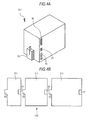
- a power supply unit 211 having a housing in the form of a square column (or a rectangular parallelepiped) may be provided as represented by a schematic perspective view in Fig. 4A.
- Fig. 4B is a conceptual illustration of a power supply unit group 210 formed by combining three power supply units 211 as thus described seen from beneath.
Landscapes
- Engineering & Computer Science (AREA)
- Chemical & Material Sciences (AREA)
- Chemical Kinetics & Catalysis (AREA)
- Electrochemistry (AREA)
- General Chemical & Material Sciences (AREA)
- Manufacturing & Machinery (AREA)
- Microelectronics & Electronic Packaging (AREA)
- Power Engineering (AREA)
- Charge And Discharge Circuits For Batteries Or The Like (AREA)
- Secondary Cells (AREA)
- Battery Mounting, Suspending (AREA)
Abstract
Description
- The present disclosure relates to a power supply unit.
- For example, a rechargeable battery pack has been made public by
JP-A-9-007644 - In the rechargeable battery pack having such a configuration, the DC-DC converter 5 stabilizes the terminal voltage of the secondary battery 3 to a predetermined value, and the remaining power detector 6 detects the terminal voltage corresponding to the remaining power of the secondary battery 3. Thus, the remaining power of the secondary battery 3 can be easily detected with a high level of regulation and user friendliness achieved as thus described.
- Some users want to use a plurality of battery packs (power supply units) by combining the battery packs in such an appropriate manner that they can be efficiently recharged. The users also want to use a plurality of battery packs (power supply units) having different capacities in combination. The rechargeable battery pack disclosed in the above mentioned patent publication was devised on an assumption that it would be used alone, and it is therefore difficult to use a plurality of such rechargeable battery packs in combination.
- It is therefore desirable to provide a power supply unit which can be easily combined with other identical units to use a plurality of such power supply units.
- Various respective aspects and features of the invention are defined in the appended claims. Combinations of features from the dependent claims may be combined with features of the independent claims as appropriate and not merely as explicitly set out in the claims.
- An embodiment of the present disclosure is directed to a power supply unit including (A) a housing having a shape like a polygonal column, (B) a secondary battery cell contained in the housing, (C) charge/discharge control means contained in the housing and connected to the secondary battery cell, (D) at least one power input section disposed on the housing and connected to the charge/discharge control means, and (E) at least one power output section disposed on the housing and connected to the charge/discharge control means.
- The housing of the power supply unit according to an embodiment of the present disclosure has a shape like a polygonal column, and a plurality of such power supply units can be combined. Since at least power input section and at least one power output section are disposed on the housing, a power input section and a power output section can be connected between adjoining power supply units, which allows a plurality of such power supply units to be easily combined. For example, a plurality of power supply units of various types having different capacities may be combined or mixed to use them collectively as one power supply unit group. It is therefore possible to provide power supply units having flexibility to be adapted to increasing applications of such units and to satisfy various needs in the fields of application. Further, a plurality of power supply units of various types can be combined or mixed to use them collectively as one power supply unit group even if they are different from each other in the degree of deterioration, cumulative time of operation, and the number of recharging operations performed thereon. Secondary battery cells having different capacities and voltages can be used collectively to form one power supply unit group.
- Embodiments of the invention will now be described with reference to the accompanying drawings, throughout which like parts are referred to by like references, and in which:
Fig. 1A is a schematic perspective view of a power supply unit group obtained by combining three power supply units according to an embodiment of the present disclosure; -
Fig. 1B is a schematic view of the power supply unit group seen from above; -
Fig. 1C is a schematic view of the interior of a power supply unit seen from above; -
Fig. 2 is a block diagram of charge/discharge control means of the power supply unit of an embodiment; -
Fig. 3A is a schematic view of a power supply unit group obtained by six power supply units according to an embodiment of the present disclosure seen from above; -
Fig. 3B is a schematic perspective view of a power supply unit having a housing in the form of a regular triangular column; -
Fig. 4A is a schematic perspective view of a power supply unit having a housing in the form of a square column; and -
Fig. 4B is a conceptual illustration of a power supply unit group formed by combining three power supply units as shown inFig. 4A seen from beneath. - The present disclosure will now be detailed based on an embodiment thereof with reference to the accompanying drawings. The present disclosure is not limited to the described embodiments, and various numerical values and materials mentioned below in association with the example embodiments are merely examples. The following items will be described in the order listed.
- 1. General Description of Power Supply Unit According to the Present Disclosure
- 2. Embodiment (Power Supply Unit According to the Present Disclosure) and Others
- A charge/discharge control unit of a power supply unit according to one embodiment of the present disclosure may include an integrated circuit for controlling charging and discharging and a DC-DC converter. The DC-DC converter is included in the charge/discharge control unit to allow an voltage output from the power supply unit to be output from the unit after being stabilized at a predetermined value. The integrated circuit for controlling charging and discharging and the DC-DC converter may be an integrated circuit for controlling charging and discharging and a DC-DC converter of types which are known in the related art.
- A power supply unit according to one embodiment of the present disclosure including the above-described preferable features may further include: (F) at least one information input section disposed in a housing and connected to the charge/discharge control unit; and (G) at least one information output section disposed in the housing and connected to the charge/discharge control unit. When such a configuration is employed, a plurality of power supply units as a whole can be connected to a controller through a communication unit. Thus, the plurality of power supply units can be controlled by the controller. Information can be transmitted/received or exchanged between the plurality of power supply units. States of operation of the plurality of power supply units, e.g., replacement of any of the units, can be checked. The states of operation of the plurality of power supply units can be displayed. An alternative configuration may be employed, in which a power input section also serves as the information input section and a power output section also serves as the information output section.
- In a power supply unit according to one embodiment of the present disclosure having the above-described preferable features and configuration, the power input section may be constituted by a USB terminal section, and the power output section may be constituted by a USB terminal section which can be engaged with the power input section constituted by a USB terminal section of another power supply unit. In a power supply unit according to one embodiment of the present disclosure having the above-described preferable features and having the configuration including at least one information input section and at least one information output section, the power input section and the power output section may be constituted by wireless power transmission circuits. Specifically, the wireless power transmission circuits (wireless power transmission systems) may employ, for example, an electromagnetic induction method or a magnetic field resonance method, but the present disclosure is not limited to such methods.
- In a power supply unit having various preferable features and a preferable configuration as described above, the housing preferably has such a shape that a plurality of the housings can be disposed side by side without a space between them. Specifically, when it is assumed that the housing which is in the form of a polyhedral column is cut along an imaginary plane orthogonal to the axis of the same, the shape of the section may be any of triangular shapes including an equilateral triangle, any of quadrangular shapes including a square, a rectangle, and a parallelogram, an equilateral hexagonal shape, or an arbitrary shape enclosed by line segments and/or curves. When the housing has a square or rectangular sectional shape, the housing is in the form of a cube or a rectangular parallelepiped.
- The housing of a power supply unit having various preferable features and a preferable configuration as described above is desirably in the form of a regular hexagonal column. In this case, the power input section may be provided on an odd-numbered lateral surface of the housing in the form of a regular hexagonal column, and the power output section may be provided on an even-numbered lateral surface of the housing in the form of a regular hexagonal column. The power input section may be provided on all odd-numbered lateral surfaces of the housing in the form of a regular hexagonal column, and the section may alternatively be provided on some of those surfaces. Similarly, the power output section may be provided on all even-numbered lateral surfaces of the housing in the form of a regular hexagonal column, and the section may alternatively be provided on some of those surfaces.
- In a power supply unit having various preferable features and a preferable configuration as described above, an input display unit indicating whether power is input or not connected to the charge/discharge control unit may be disposed in the vicinity of the power input unit, and an output display unit indicating whether power is output or not connected to the charge/discharge control unit may be disposed in the vicinity of the power output unit. In this case, the input display unit and the output display unit may be formed by a display portion including an arrow-shaped member transmitting light and a light-emitting element disposed inside the display portion. Further, the input display unit and the output display unit may be disposed on a top surface of the housing.
- A power supply unit having various preferable features and a preferable configuration as described above (such a unit may be hereinafter simply referred to as "a power supply unit according to the present disclosure") may be disposed such that a plurality of the power supply units are combined by connecting a power input section and a power output section of each adjoining pair of the power supply units. Thus, a group of power supply units is formed. The minimum number of power supply units to form a group of power supply units is 2, and there is no upper limit for the number of units to be grouped. A group of power supply units may be formed by combining a plurality of power supply units which are horizontally arranged. Alternatively, a group of power supply units may be formed by combining a plurality of power supply units which are vertically arranged or stacked one over another. Still alternatively, a plurality of groups of horizontally combined power supply units may be combined vertically (or stacked one over another). Power supply units forming a power supply unit group may be either the same or different in terms of capacity and size. The power supply units may be either the same or different in terms of the number, the output voltage, or the capacity of the secondary batteries forming part of the units.
- Such a group of power supply units is supplied with power from an external power supply through the power input section of at least one of power supply units, whereby the secondary battery cells of the power supply units are charged. The external power supply and the power input section may be connected using a wiring, and connection may alternatively be established using a wireless power transmission method such as the electromagnetic induction method or the magnetic field resonance method. One or a plurality of power consuming apparatuses is connected to the power output section of at least one of the power supply units. That is, one or a plurality of power consuming apparatuses may be connected to one location of the group of power supply units. Alternatively, one or a plurality of power consuming apparatuses may be connected to a plurality of locations of the group of power supply units. The power consuming apparatuses and the power input section may be connected using a wiring, and connection may alternatively be established using a wireless power transmission method such as the electromagnetic induction method or the magnetic field resonance method. For example, such power consuming apparatuses may include electronic apparatuses such as personal computers, television receivers, displays of various types, mobile phones, PDAs, digital still cameras, video cameras, camcorders, and music players, power tools such as power drills, lighting apparatuses such as room lamps, power supply units or home energy servers (home storage batteries), medical instruments, and toys. However, the present disclosure is not limited to such apparatuses. Not only the commercial power source but also other power supplies of various types may be used as the external power supply, including solar batteries, fuel cells, aerogenerators, micro hydroelectric generators, and geothermal power generators. However, the power supply unit according to the present disclosure is not limited to such external power supplies. The housing may be made of a plastic material such as a thermoplastic resin. Specifically, the housing may be fabricated using, for example, a polyolefine type resin such as a polyethylene resin or a polypropylene resin; a polyamide type resin such as polyamide 6, polyamide 66, or polyamide MXD6; a polyoxymethylene (POM or polyacetal) resin; a polyester type resin such as a polyethylene terephthalate (PET) resin, or a polybutylene terephthalate (PBT) resin; a polyphenylene sulfide resin; a styrene type resin such as a polystyrene resin, an ABS resin, an AES resin, or an AS resin; a methacrylate resin; a polycarbonate resin; a modified polyphenylene ether (PPE) resin; a polysulfone resin; a polyether sulfone resin; a polyarylate resin; a polyether imide resin; a polyamide-imide resin; a polyimide type resin; a polyether ketone resin; a polyether ether ketone resin; a polyester carbonate resin; or a liquid crystal polymer. However, the present disclosure is not limited to such materials.
- When power supply units according to the present disclosure are connected to a controller through a communication unit or when the power supply units are connected to each other through a communication unit, the communication unit may be a common telephone network or an optical fiber network including the internet communication network, a communication unit according to ZigBee, a wireless LAN, a communication unit according to RC232, a USB communication unit, an infrared communication unit according to IrDA or the like, a communication unit according to Bluetooth which is one of wireless LAN protocols or HomeRF, or a combination of communication units as thus described. However, the present disclosure is not limited to such communication units. A personal computer may serve as the controller or part of the controller. A mobile terminal including a display may be provided, and the controller and the mobile terminal may be connected through the communication unit. Such a configuration allows the state of operation of the power supply unit or a group of the power supply units to be remotely checked. For example, the mobile terminal may be a mobile phone, a PDA (personal digital assistant), or a notebook type personal computer. However, the present disclosure is not limited to such a mobile terminal.
- An embodiment of a power supply unit according to the present disclosure will now be described.
Fig. 1A is a perspective view of a power supply unit group obtained by combining power supply units according to an embodiment.Fig. 1B is a schematic view of the power supply unit group seen from above.Fig. 1C is a schematic view of the interior of a power supply unit seen from above.Fig. 2 is a block diagram of a charge/discharge control unit. - A
power supply unit 11 according to an embodiment includes ahousing 20 having a polygonal columnar shape, asecondary battery cell 30 contained in thehousing 20, a charge/discharge control unit 40 contained in thehousing 20 and connected to thesecondary battery cell 30, at least onepower input section 51 disposed on thehousing 20 and connected to the charge/discharge unit 40, and at least onepower output section 53 disposed on thehousing 20 and connected to the charge/discharge control unit 40. While a powersupply unit group 10 according to the present embodiment is formed by combining threepower supply units - In a
power supply unit 11 according to the present embodiment, thehousing 20 has such a shape that a plurality of thehousings 20 can be disposed side by side without a space between them. Specifically, when it is assumed that thehousing 20 is cut along an imaginary plane orthogonal to the axis of the same, the section has a regular hexagonal shape. Thepower input section 51 is provided on an odd-numbered lateral surface of thehousing 20 having a regular hexagonal shape. Thepower output section 53 is provided on an even-numbered lateral surface of thehousing 20 having a regular hexagonal shape. Although onepower input section 51 and threepower output sections 53 are provided in the illustrated embodiment, the power supply unit according to other embodiments is not limited to such a configuration. Thepower input section 51 and thepower output sections 53 are connected to the charge/discharge control unit 40 through wirings which are not shown. The threepower supply units 11 inFig. 1A have different heights. That is, the threepower supply units 11 have different capacities. Specifically, thehousings 20 are different from each other in terms of the number ofsecondary battery cells 30 contained therein. Thehousings 20 are provided by molding a plastic material such as an ABS resin. - A
power supply unit 11 according to the embodiment further includes at least one information input section disposed in thehousing 20 and connected to the charge/discharge control unit 40 and at least one information output section disposed in thehousing 20 and connected to the charge/discharge control unit 40. Specifically, the information input section and the information output section areUSB terminal sections 55. More specifically, the information input section is a USB terminal, and the information output section is a USB socket. TheUSB terminal sections 55 are connected to the charge/discharge control unit 40 through wirings which are not shown. Information can be exchanged between the plurality ofpower supply units 11 by connecting the information input sections and the information output sections of the plurality ofpower supply units 11 to each other through USB cables. The information output section of any of thepower supply units 11 may be connected to, for example, a controller (not shown) configured by a personal computer through a USB cable. Then, the plurality ofpower supply units 11 can be controlled by the controller. Information can be transmitted/received or exchanged between the plurality ofpower supply units 11. States of operation of the plurality ofpower supply units 11, e.g., replacement of any of the units, can be checked. The states of operation of the plurality ofpower supply units 11 can be displayed. The controller and thepower supply units 11 may alternatively connected according to, for example, the ZigBee standard. - As occasion demands, the
power input section 51 may be constituted by a USB terminal section, and thepower output section 53 may be constituted by a USB terminal section which can be engaged with thepower input section 51 constituted by the USB terminal section. Specifically, a micro USB terminal and a micro USB socket may be used as thepower input section 51 and thepower output section 53, respectively. Alternatively a micro USB terminal and a micro USB socket may be used as thepower output section 53 and thepower input section 51, respectively. - The charge/
discharge control unit 40 of apower supply unit 11 according to the embodiment includes an integrated circuit (charge circuit) 43 of a well known type and a DC-DC converter (DC-DC converter for output) 44 of a known type. The charge/discharge control unit 40 further includes anMPU 41, astorage unit 42 constituted by an EEROM, a control system DC-DC converter 45, and a DC-DC converter 46 for USB. For example, input power at a voltage of 12 volts is input to the integrated circuit (charge circuit) 43 from an external power supply such as a commercial power supply or a solar battery. Then, the integrated circuit (charge circuit) 43 operates in the well-known manner to charge thesecondary battery cell 30 which is a lithium ion secondary battery. Power is supplied from thesecondary battery cell 30 to theMPU 41 and thestorage unit 42 through the control system DC-DC converter 45. Power is also supplied from thesecondary battery cell 30 outside through the DC-DC converter 44 for output and thepower output section 53. In addition, power is supplied to theUSB terminal section 55 through the DC-DC converter 46 for USB. The features such as theMPU 41 are mounted on a printedcircuit board 47. - The
power input section 51 and thepower output section 53 have structures which can be engaged with each other. Specifically, thepower input section 51 may have a structure in the form of a projection, and thepower output section 53 may have a structure in the form of a recess. Apower input section 51 and apower output section 53 of each pair of adjoiningpower supply units 11 can be engaged with each other to provide a powersupply unit group 10 which is a combination of a plurality ofpower supply units 11. The charge/discharge control unit 40 has such a structure that the state of engagement between apower input section 51 and apower output section 53 can be detected by a detection unit (e.g., a switch) which is not shown. - In the vicinity of the
power input section 51 of apower supply unit 11, there is provided aninput display unit 52 which is connected to the charge/discharge control unit 40 and which displays whether power is input or not. In the vicinity of thepower output section 53, there is provided anoutput display unit 54 which is connected to the charge/discharge control unit 40 and which displays whether power is output or not. Theinput display unit 52 and theoutput display unit 54 are formed by a display portion including an arrow-shaped member transmitting light and a light-emitting element (not shown) disposed inside the display portion. Specifically, the light-emitting element may be an LED. Theinput display unit 52 and theoutput display unit 54 are disposed on the top surface of thehousing 20. The light-emitting elements are connected to the charge/discharge control unit 40 through wirings, and the light-emitting elements are turned on and off under control exercised by the charge/discharge control unit 40. More specifically, the charge/discharge control unit 40 checks the state of engagement of thepower input section 51 and thepower output section 53 and detects a flow of a current between thepower input section 51 and thepower output section 53. The light-emitting elements are turned on and off under control exercised based on the result of such operations. InFig. 1B , theinput display unit 52 represented by black arrows indicate that power is supplied (input) from an external power supply to the respectivepower input sections 51 located in the vicinity thereof. The outputpower display unit 54 represented by black arrows indicate that power is supplied (output) outside or supplied to the adjacentpower supply units 11 from the respective power output sections located in the vicinity thereof. The same applies in the following description. A charging state display unit (not shown) constituted by an LED for displaying the state of charging and a discharging state display unit or a remaining power display unit (not shown) constituted by an LED for displaying the state of discharging may be provided on thehousing 20 of thepower supply unit 11, and those units may connected to the charge/discharge control unit 40 to control the operations of them by the charge/discharge control unit 40. Theinput display unit 52 and theoutput display unit 54 may be made to also serve as the charging state display unit and the discharging state display unit or the remaining power display unit, respectively. In this case, for example, the functions of the charging state display unit and the discharging state display unit or the remaining power display unit can be achieved in the form of a blinking state of the light-emitting elements. - Power is supplied to the power
supply unit group 10 of the present embodiment from an external power supply through apower input section 51 provided in one location of the group to charge thesecondary battery cells 30 of the threepower supply units 11. Power is supplied (output) to power consuming apparatuses through apower output section 53 provided in one location or two locations of the group to drive the power consuming apparatuses. - In the present embodiment, the
housings 20 of thepower supply units 11 are in the form of polygonal columns (specifically, regular hexagonal columns), and the plurality ofpower supply units 11 can therefore be combined without a space between them. Apower input section 51 and apower output section 53 can be connected between each pair of adjoiningpower supply units 11 to allow the plurality ofpower supply units 11 to be easily combined. For example, a plurality ofpower supply units 11 of various types having different capacities may be combined or mixed to use them collectively as one powersupply unit group 10. - While an example embodiment of the present disclosure has been primarily described, the present disclosure is not limited to the embodiment. The embodiment has merely showed examples of the configurations and structures of a power supply unit, a power supply unit group, a secondary battery cell, a charge/discharge control unit, a power input section, and a power output section in accordance with embodiments of the invention according to the present disclosure, and modifications may be made as occasion demands. At least one power input section and at least one power output section disposed in a
housing 20 and connected to the charge/discharge control unit 40 as described above may employ the magnetic field resonance method. Specifically, a power transmitter including a high frequency power supply circuit and a matching circuit and a power receiver including a matching circuit, a high-speed rectifier circuit, and a power supply conversion circuit may be incorporated in the charge/discharge control unit 40. The power output section may be constituted by a power transmission device connected to the matching circuit forming part of the power transmitter. The power input section may be constituted by a power receiving device connected to the matching circuit forming part of the power receiver. - For example, six power supply units according to the present disclosure may be combined to form a power supply unit group as shown in
Fig. 3A. Fig. 3A is a schematic view of such a power supply unit group seen from above. In the illustrated example, each power supply unit includes threepower input sections 51 and threepower output sections 53. - As shown in
Fig. 3B , apower supply unit 111 having ahousing 120 in the form of a regular triangular column may be provided.Reference numeral 56A represents pins, and reference numeral 56B represents holes which are engaged with the pins. When apower supply unit 111 is combined with another by engagingpins 56A and holes 56B with each other as thus described, it is possible to prevent an excessive force from being applied to apower input section 51 and apower output section 53.Reference numeral 57 represents a knob operated to allow thepower output section 53 to be projected and retracted. Further,reference numeral 58 represents a display unit which is a combination of a charging state display unit and a discharging state display unit or a remaining power display unit, and the display unit is formed by arranging a plurality of LEDs. Thedisplay unit 58 is connected to a charge/discharge control unit 40. - A
power supply unit 211 having a housing in the form of a square column (or a rectangular parallelepiped) may be provided as represented by a schematic perspective view inFig. 4A. Fig. 4B is a conceptual illustration of a powersupply unit group 210 formed by combining threepower supply units 211 as thus described seen from beneath. - The present disclosure contains subject matter related to that disclosed in Japanese Priority Patent Application
JP 2010-205884 - It should be understood by those skilled in the art that various modifications, combinations, sub-combinations and alterations may occur depending on design requirements and other factors insofar as they are within the scope of the appended claims or the equivalents thereof.
Claims (12)
- A power supply unit comprising:(A) a housing having a shape like a polygonal column;(B) a secondary battery cell contained in the housing;(C) charge/discharge control means contained in the housing and connected to the secondary battery cell;(D) at least one power input section disposed on the housing and connected to the charge/discharge control means; and(E) at least one power output section disposed on the housing and connected to the charge/discharge control means.
- A power supply unit according to Claim 1, wherein the charge/discharge control means includes an integrated circuit for controlling charging and discharging and a DC-DC converter.
- A power supply unit according to Claim 1, further comprising:(F) at least one information input section disposed on the housing and connected to the charge/discharge control means; and(G) at least one information output section disposed on the housing and connected to the charge/discharge control means.
- A power supply unit according to Claim 3, wherein
the power input section also serves as the information input section; and
the power output section also serves as the information output section. - A power supply unit according to Claim 1, wherein
the power input section includes a USB terminal section; and
the power output section includes a USB terminal section which is engageable with a power input section including a USB terminal section. - A power supply unit according to Claim 1, wherein the power input section and the power output section include a wireless power transmission circuit.
- A power supply unit according to Claim 1, wherein the housing has such a shape that a plurality of the housings can be arranged side by side without a space between them.
- A power supply unit according to Claim 1, wherein the housing has a shape like a regular hexagonal column.
- A power supply unit according to Claim 8, wherein
the power input section is provided on an odd-numbered lateral surface of the housing having a shape like a regular hexagonal column; and
the power output section is provided on an even-numbered lateral surface of the housing having a shape like a regular hexagonal column. - A power supply unit according to Claim 1, comprising:input display means indicating whether power is input or not provided in the vicinity of the power input section and connected to the charge/discharge control means; andoutput display means indicating whether power is output or not provided in the vicinity of the power output section and connected to the charge/discharge control means.
- A power supply unit according to Claim 10, wherein the input display means and output display means include a display portion including an arrow-like member transmitting light and a light-emitting element disposed inside the display portion.
- A power supply unit according to Claim 11, wherein the input display means and output display means are disposed on a top surface of the housing.
Applications Claiming Priority (1)
| Application Number | Priority Date | Filing Date | Title |
|---|---|---|---|
| JP2010205884A JP2012064353A (en) | 2010-09-14 | 2010-09-14 | Power supply unit |
Publications (2)
| Publication Number | Publication Date |
|---|---|
| EP2429015A1 true EP2429015A1 (en) | 2012-03-14 |
| EP2429015B1 EP2429015B1 (en) | 2013-11-27 |
Family
ID=44785316
Family Applications (1)
| Application Number | Title | Priority Date | Filing Date |
|---|---|---|---|
| EP11179846.8A Not-in-force EP2429015B1 (en) | 2010-09-14 | 2011-09-02 | Power supply unit |
Country Status (4)
| Country | Link |
|---|---|
| US (1) | US20120062180A1 (en) |
| EP (1) | EP2429015B1 (en) |
| JP (1) | JP2012064353A (en) |
| CN (1) | CN102403550A (en) |
Cited By (4)
| Publication number | Priority date | Publication date | Assignee | Title |
|---|---|---|---|---|
| EP3051658A1 (en) * | 2015-02-02 | 2016-08-03 | Black & Decker Inc. | Battery pack & power tool system |
| EP3358702A1 (en) * | 2017-02-03 | 2018-08-08 | Solar Dock Limited | A photovoltaic powered charging station for simultaneously charging a plurality of portable electronic devices |
| EP3522313A4 (en) * | 2016-09-30 | 2019-09-04 | BYD Company Limited | POWER SUPPLY CABINET |
| GR1010221B (en) * | 2021-08-17 | 2022-04-13 | Χρηστος Προδρομου Φιλιππιδης | OPERATED PORTABLE CHARGER (POWER BANK) FREE SHAPE |
Families Citing this family (15)
| Publication number | Priority date | Publication date | Assignee | Title |
|---|---|---|---|---|
| US8525924B2 (en) * | 2008-12-29 | 2013-09-03 | Red.Com, Inc. | Modular motion camera |
| US8525925B2 (en) * | 2008-12-29 | 2013-09-03 | Red.Com, Inc. | Modular digital camera |
| TWM438007U (en) * | 2011-12-30 | 2012-09-21 | Univ Chung Yuan Christian | Field environment detection device |
| JP6041642B2 (en) * | 2012-11-30 | 2016-12-14 | 株式会社マキタ | Electric tool charging device |
| KR101596266B1 (en) * | 2013-03-05 | 2016-02-22 | 주식회사 엘지화학 | Polyhedral Battery Cell and Battery Module Assembly Employed with the Same |
| US9509153B2 (en) * | 2013-12-09 | 2016-11-29 | Kenneth E. Clark | Portable multiple mobile electronic device charging station |
| ES2748454T3 (en) | 2014-04-04 | 2020-03-16 | Red Com Llc | Diffusion module for digital camera |
| US20160093926A1 (en) * | 2014-09-29 | 2016-03-31 | Elite Lifestyle Products L.P. | Battery pack |
| JP2019507996A (en) | 2015-12-14 | 2019-03-22 | レッド.コム,エルエルシー | Modular digital camera and mobile phone |
| US12148938B1 (en) | 2019-03-12 | 2024-11-19 | Christopher Paul Carroll | Modular portable and backup power systems and methods |
| US11573028B2 (en) * | 2019-06-03 | 2023-02-07 | Johnson Controls Tyco IP Holdings LLP | Heater assembly of a heating unit |
| CN215988997U (en) * | 2021-06-25 | 2022-03-08 | 宁德时代新能源科技股份有限公司 | Batteries and Electrical Devices |
| CN115882136A (en) * | 2021-09-29 | 2023-03-31 | 宁德时代新能源科技股份有限公司 | Battery cell, manufacturing method and system thereof, battery, and electrical device |
| CN115966816B (en) * | 2021-10-12 | 2025-02-21 | 宁德时代新能源科技股份有限公司 | Battery cell, battery and electricity utilization device |
| JP7670298B2 (en) * | 2021-12-21 | 2025-04-30 | エルジー エナジー ソリューション リミテッド | Battery pack and energy storage device including the same |
Citations (9)
| Publication number | Priority date | Publication date | Assignee | Title |
|---|---|---|---|---|
| DE4337786A1 (en) * | 1993-11-05 | 1995-05-11 | Philips Patentverwaltung | Battery with a voltage converter connected to the battery |
| JPH097644A (en) | 1995-06-22 | 1997-01-10 | Fuji Elelctrochem Co Ltd | Rechargeable battery pack |
| US5778325A (en) * | 1993-09-15 | 1998-07-07 | Ericsson, Inc. | System for providing electrical power to modular electronic components |
| US6406812B1 (en) * | 1999-04-23 | 2002-06-18 | Oldham France S.A. | Continuous current supply for electrical automotive vehicle |
| US6849357B1 (en) * | 2000-07-04 | 2005-02-01 | Matsushita Electric Industrial Co., Ltd. | Battery, a process for producing the battery, a process for producing a battery case, and a battery pack |
| US20060091849A1 (en) * | 2004-11-01 | 2006-05-04 | Huynh Due Q | Modular battery pack |
| WO2009017406A2 (en) * | 2007-07-27 | 2009-02-05 | N.V.Nederlandsche Apparatenfabriek Nedap | Battery and charger for a battery and system of the battery and a charger |
| US20090252994A1 (en) * | 2008-04-04 | 2009-10-08 | Alexander Livingston | Battery pack system |
| JP2010205884A (en) | 2009-03-03 | 2010-09-16 | Murata Mfg Co Ltd | Method of manufacturing electronic component |
Family Cites Families (13)
| Publication number | Priority date | Publication date | Assignee | Title |
|---|---|---|---|---|
| JP3457461B2 (en) * | 1996-03-29 | 2003-10-20 | 日機装株式会社 | Non-aqueous electrolyte secondary battery and assembled battery |
| US5963014A (en) * | 1998-07-15 | 1999-10-05 | E. Lead Electronic Co., Ltd. | Serially connected charger |
| GB2362769A (en) * | 2000-05-26 | 2001-11-28 | Nokia Mobile Phones Ltd | Battery charging circuit in which power is supplied via a communications port |
| JP2002134080A (en) * | 2000-10-27 | 2002-05-10 | Hitachi Ltd | Battery pack and electronic device using the same |
| US20040131927A1 (en) * | 2003-01-03 | 2004-07-08 | Arthur Holland | Battery with insulative tubular housing |
| US20060267547A1 (en) * | 2005-05-27 | 2006-11-30 | Mark Godovich | Replacement battery pack with built-in charging circuitry and power connector, and AC adapter for reading charging status of replacement battery pack |
| JP2007095417A (en) * | 2005-09-28 | 2007-04-12 | Sony Corp | battery pack |
| US20070273325A1 (en) * | 2006-02-24 | 2007-11-29 | Black & Decker Inc. | Power station with built in battery charger |
| JP4191781B1 (en) * | 2007-12-17 | 2008-12-03 | 和征 榊原 | Battery pack |
| JP4661900B2 (en) * | 2008-04-17 | 2011-03-30 | ソニー株式会社 | Wireless communication apparatus, power supply method, program, and wireless communication system |
| US20100106353A1 (en) * | 2008-10-28 | 2010-04-29 | Ford Global Technologies, Llc | Regenerative braking and charge flow state indication system for a hybrid electric vehicle |
| TWM385097U (en) * | 2010-01-05 | 2010-07-21 | Hercules Electronics Co Ltd | Secondary battery |
| US8400104B2 (en) * | 2010-04-06 | 2013-03-19 | L & P Property Management Company | Gangable inductive battery charger |
-
2010
- 2010-09-14 JP JP2010205884A patent/JP2012064353A/en active Pending
-
2011
- 2011-09-02 EP EP11179846.8A patent/EP2429015B1/en not_active Not-in-force
- 2011-09-07 US US13/226,933 patent/US20120062180A1/en not_active Abandoned
- 2011-09-07 CN CN2011102759662A patent/CN102403550A/en active Pending
Patent Citations (9)
| Publication number | Priority date | Publication date | Assignee | Title |
|---|---|---|---|---|
| US5778325A (en) * | 1993-09-15 | 1998-07-07 | Ericsson, Inc. | System for providing electrical power to modular electronic components |
| DE4337786A1 (en) * | 1993-11-05 | 1995-05-11 | Philips Patentverwaltung | Battery with a voltage converter connected to the battery |
| JPH097644A (en) | 1995-06-22 | 1997-01-10 | Fuji Elelctrochem Co Ltd | Rechargeable battery pack |
| US6406812B1 (en) * | 1999-04-23 | 2002-06-18 | Oldham France S.A. | Continuous current supply for electrical automotive vehicle |
| US6849357B1 (en) * | 2000-07-04 | 2005-02-01 | Matsushita Electric Industrial Co., Ltd. | Battery, a process for producing the battery, a process for producing a battery case, and a battery pack |
| US20060091849A1 (en) * | 2004-11-01 | 2006-05-04 | Huynh Due Q | Modular battery pack |
| WO2009017406A2 (en) * | 2007-07-27 | 2009-02-05 | N.V.Nederlandsche Apparatenfabriek Nedap | Battery and charger for a battery and system of the battery and a charger |
| US20090252994A1 (en) * | 2008-04-04 | 2009-10-08 | Alexander Livingston | Battery pack system |
| JP2010205884A (en) | 2009-03-03 | 2010-09-16 | Murata Mfg Co Ltd | Method of manufacturing electronic component |
Cited By (9)
| Publication number | Priority date | Publication date | Assignee | Title |
|---|---|---|---|---|
| EP3051658A1 (en) * | 2015-02-02 | 2016-08-03 | Black & Decker Inc. | Battery pack & power tool system |
| US9917457B2 (en) | 2015-02-02 | 2018-03-13 | Black & Decker Inc. | Power tool with USB connection |
| EP3522313A4 (en) * | 2016-09-30 | 2019-09-04 | BYD Company Limited | POWER SUPPLY CABINET |
| AU2017336635B2 (en) * | 2016-09-30 | 2020-08-13 | Byd Company Limited | Power cabinet |
| AU2017336635B9 (en) * | 2016-09-30 | 2020-08-27 | Byd Company Limited | Power cabinet |
| EP4322280A3 (en) * | 2016-09-30 | 2025-01-29 | BYD Company Limited | Power supply cabinet |
| US12555831B2 (en) | 2016-09-30 | 2026-02-17 | Byd Company Limited | Power cabinet |
| EP3358702A1 (en) * | 2017-02-03 | 2018-08-08 | Solar Dock Limited | A photovoltaic powered charging station for simultaneously charging a plurality of portable electronic devices |
| GR1010221B (en) * | 2021-08-17 | 2022-04-13 | Χρηστος Προδρομου Φιλιππιδης | OPERATED PORTABLE CHARGER (POWER BANK) FREE SHAPE |
Also Published As
| Publication number | Publication date |
|---|---|
| US20120062180A1 (en) | 2012-03-15 |
| JP2012064353A (en) | 2012-03-29 |
| CN102403550A (en) | 2012-04-04 |
| EP2429015B1 (en) | 2013-11-27 |
Similar Documents
| Publication | Publication Date | Title |
|---|---|---|
| EP2429015B1 (en) | Power supply unit | |
| US9281702B2 (en) | Electric storage unit group, charger, electronic device, electric vehicle, method for charging electric storage unit group, method for discharging electric storage unit group, method for supplying and receiving power, and method for determining charging/discharging route in electric storage unit group | |
| US9041338B2 (en) | Portable solar power supply | |
| US12191692B2 (en) | Smart ring power and charging | |
| US10003204B2 (en) | Portable multiple mobile electronic device charging station | |
| CN102403793B (en) | Power supply device | |
| US20090179610A1 (en) | Mobile power bank | |
| US20130069583A1 (en) | Power module for portable devices | |
| US20120319487A1 (en) | Integrated Battery Backup and Charging for Mobile Devices | |
| EP2578069A2 (en) | Power module for portable devices | |
| EP3410566A1 (en) | Power supply device and power reception/supply device | |
| KR200473025Y1 (en) | Portable external power-supplying device | |
| US10873217B2 (en) | Magnetic field formation device, power supplying device, power receiving device, power receiving/supplying device, and portable device | |
| CN205141745U (en) | Composite power supply | |
| JP2013247091A (en) | Battery pack | |
| Crowell | Battery arrays, rechargable Li-ion battery power sources for marine applications | |
| US9941731B1 (en) | Carry bag or purse with remote charging and illumination features | |
| US20130320917A1 (en) | Mobile Power Device with Projection | |
| KR200371122Y1 (en) | Direct current supplier with the multiple USB port | |
| JP2013246906A (en) | Battery pack | |
| TWM518841U (en) | Composite power supply device |
Legal Events
| Date | Code | Title | Description |
|---|---|---|---|
| 17P | Request for examination filed |
Effective date: 20110922 |
|
| AK | Designated contracting states |
Kind code of ref document: A1 Designated state(s): AL AT BE BG CH CY CZ DE DK EE ES FI FR GB GR HR HU IE IS IT LI LT LU LV MC MK MT NL NO PL PT RO RS SE SI SK SM TR |
|
| AX | Request for extension of the european patent |
Extension state: BA ME |
|
| PUAI | Public reference made under article 153(3) epc to a published international application that has entered the european phase |
Free format text: ORIGINAL CODE: 0009012 |
|
| GRAP | Despatch of communication of intention to grant a patent |
Free format text: ORIGINAL CODE: EPIDOSNIGR1 |
|
| INTG | Intention to grant announced |
Effective date: 20130624 |
|
| GRAS | Grant fee paid |
Free format text: ORIGINAL CODE: EPIDOSNIGR3 |
|
| GRAA | (expected) grant |
Free format text: ORIGINAL CODE: 0009210 |
|
| AK | Designated contracting states |
Kind code of ref document: B1 Designated state(s): AL AT BE BG CH CY CZ DE DK EE ES FI FR GB GR HR HU IE IS IT LI LT LU LV MC MK MT NL NO PL PT RO RS SE SI SK SM TR |
|
| REG | Reference to a national code |
Ref country code: GB Ref legal event code: FG4D |
|
| REG | Reference to a national code |
Ref country code: CH Ref legal event code: EP |
|
| REG | Reference to a national code |
Ref country code: AT Ref legal event code: REF Ref document number: 643023 Country of ref document: AT Kind code of ref document: T Effective date: 20131215 |
|
| REG | Reference to a national code |
Ref country code: IE Ref legal event code: FG4D |
|
| REG | Reference to a national code |
Ref country code: DE Ref legal event code: R096 Ref document number: 602011003936 Country of ref document: DE Effective date: 20140123 |
|
| REG | Reference to a national code |
Ref country code: NL Ref legal event code: VDEP Effective date: 20131127 |
|
| REG | Reference to a national code |
Ref country code: AT Ref legal event code: MK05 Ref document number: 643023 Country of ref document: AT Kind code of ref document: T Effective date: 20131127 |
|
| REG | Reference to a national code |
Ref country code: LT Ref legal event code: MG4D |
|
| PG25 | Lapsed in a contracting state [announced via postgrant information from national office to epo] |
Ref country code: NL Free format text: LAPSE BECAUSE OF FAILURE TO SUBMIT A TRANSLATION OF THE DESCRIPTION OR TO PAY THE FEE WITHIN THE PRESCRIBED TIME-LIMIT Effective date: 20131127 Ref country code: IS Free format text: LAPSE BECAUSE OF FAILURE TO SUBMIT A TRANSLATION OF THE DESCRIPTION OR TO PAY THE FEE WITHIN THE PRESCRIBED TIME-LIMIT Effective date: 20140327 Ref country code: NO Free format text: LAPSE BECAUSE OF FAILURE TO SUBMIT A TRANSLATION OF THE DESCRIPTION OR TO PAY THE FEE WITHIN THE PRESCRIBED TIME-LIMIT Effective date: 20140227 Ref country code: LT Free format text: LAPSE BECAUSE OF FAILURE TO SUBMIT A TRANSLATION OF THE DESCRIPTION OR TO PAY THE FEE WITHIN THE PRESCRIBED TIME-LIMIT Effective date: 20131127 Ref country code: SE Free format text: LAPSE BECAUSE OF FAILURE TO SUBMIT A TRANSLATION OF THE DESCRIPTION OR TO PAY THE FEE WITHIN THE PRESCRIBED TIME-LIMIT Effective date: 20131127 Ref country code: HR Free format text: LAPSE BECAUSE OF FAILURE TO SUBMIT A TRANSLATION OF THE DESCRIPTION OR TO PAY THE FEE WITHIN THE PRESCRIBED TIME-LIMIT Effective date: 20131127 Ref country code: FI Free format text: LAPSE BECAUSE OF FAILURE TO SUBMIT A TRANSLATION OF THE DESCRIPTION OR TO PAY THE FEE WITHIN THE PRESCRIBED TIME-LIMIT Effective date: 20131127 |
|
| PG25 | Lapsed in a contracting state [announced via postgrant information from national office to epo] |
Ref country code: RS Free format text: LAPSE BECAUSE OF FAILURE TO SUBMIT A TRANSLATION OF THE DESCRIPTION OR TO PAY THE FEE WITHIN THE PRESCRIBED TIME-LIMIT Effective date: 20131127 Ref country code: CY Free format text: LAPSE BECAUSE OF FAILURE TO SUBMIT A TRANSLATION OF THE DESCRIPTION OR TO PAY THE FEE WITHIN THE PRESCRIBED TIME-LIMIT Effective date: 20131127 Ref country code: BE Free format text: LAPSE BECAUSE OF FAILURE TO SUBMIT A TRANSLATION OF THE DESCRIPTION OR TO PAY THE FEE WITHIN THE PRESCRIBED TIME-LIMIT Effective date: 20131127 Ref country code: ES Free format text: LAPSE BECAUSE OF FAILURE TO SUBMIT A TRANSLATION OF THE DESCRIPTION OR TO PAY THE FEE WITHIN THE PRESCRIBED TIME-LIMIT Effective date: 20131127 Ref country code: LV Free format text: LAPSE BECAUSE OF FAILURE TO SUBMIT A TRANSLATION OF THE DESCRIPTION OR TO PAY THE FEE WITHIN THE PRESCRIBED TIME-LIMIT Effective date: 20131127 Ref country code: AT Free format text: LAPSE BECAUSE OF FAILURE TO SUBMIT A TRANSLATION OF THE DESCRIPTION OR TO PAY THE FEE WITHIN THE PRESCRIBED TIME-LIMIT Effective date: 20131127 |
|
| PG25 | Lapsed in a contracting state [announced via postgrant information from national office to epo] |
Ref country code: PT Free format text: LAPSE BECAUSE OF FAILURE TO SUBMIT A TRANSLATION OF THE DESCRIPTION OR TO PAY THE FEE WITHIN THE PRESCRIBED TIME-LIMIT Effective date: 20140327 |
|
| PG25 | Lapsed in a contracting state [announced via postgrant information from national office to epo] |
Ref country code: EE Free format text: LAPSE BECAUSE OF FAILURE TO SUBMIT A TRANSLATION OF THE DESCRIPTION OR TO PAY THE FEE WITHIN THE PRESCRIBED TIME-LIMIT Effective date: 20131127 |
|
| REG | Reference to a national code |
Ref country code: DE Ref legal event code: R097 Ref document number: 602011003936 Country of ref document: DE |
|
| PG25 | Lapsed in a contracting state [announced via postgrant information from national office to epo] |
Ref country code: SK Free format text: LAPSE BECAUSE OF FAILURE TO SUBMIT A TRANSLATION OF THE DESCRIPTION OR TO PAY THE FEE WITHIN THE PRESCRIBED TIME-LIMIT Effective date: 20131127 Ref country code: CZ Free format text: LAPSE BECAUSE OF FAILURE TO SUBMIT A TRANSLATION OF THE DESCRIPTION OR TO PAY THE FEE WITHIN THE PRESCRIBED TIME-LIMIT Effective date: 20131127 Ref country code: PL Free format text: LAPSE BECAUSE OF FAILURE TO SUBMIT A TRANSLATION OF THE DESCRIPTION OR TO PAY THE FEE WITHIN THE PRESCRIBED TIME-LIMIT Effective date: 20131127 Ref country code: RO Free format text: LAPSE BECAUSE OF FAILURE TO SUBMIT A TRANSLATION OF THE DESCRIPTION OR TO PAY THE FEE WITHIN THE PRESCRIBED TIME-LIMIT Effective date: 20131127 |
|
| PG25 | Lapsed in a contracting state [announced via postgrant information from national office to epo] |
Ref country code: DK Free format text: LAPSE BECAUSE OF FAILURE TO SUBMIT A TRANSLATION OF THE DESCRIPTION OR TO PAY THE FEE WITHIN THE PRESCRIBED TIME-LIMIT Effective date: 20131127 |
|
| PLBE | No opposition filed within time limit |
Free format text: ORIGINAL CODE: 0009261 |
|
| STAA | Information on the status of an ep patent application or granted ep patent |
Free format text: STATUS: NO OPPOSITION FILED WITHIN TIME LIMIT |
|
| PGFP | Annual fee paid to national office [announced via postgrant information from national office to epo] |
Ref country code: DE Payment date: 20140922 Year of fee payment: 4 |
|
| 26N | No opposition filed |
Effective date: 20140828 |
|
| PGFP | Annual fee paid to national office [announced via postgrant information from national office to epo] |
Ref country code: FR Payment date: 20140919 Year of fee payment: 4 |
|
| REG | Reference to a national code |
Ref country code: DE Ref legal event code: R097 Ref document number: 602011003936 Country of ref document: DE Effective date: 20140828 |
|
| PG25 | Lapsed in a contracting state [announced via postgrant information from national office to epo] |
Ref country code: SI Free format text: LAPSE BECAUSE OF FAILURE TO SUBMIT A TRANSLATION OF THE DESCRIPTION OR TO PAY THE FEE WITHIN THE PRESCRIBED TIME-LIMIT Effective date: 20131127 |
|
| PG25 | Lapsed in a contracting state [announced via postgrant information from national office to epo] |
Ref country code: MC Free format text: LAPSE BECAUSE OF FAILURE TO SUBMIT A TRANSLATION OF THE DESCRIPTION OR TO PAY THE FEE WITHIN THE PRESCRIBED TIME-LIMIT Effective date: 20131127 Ref country code: LU Free format text: LAPSE BECAUSE OF FAILURE TO SUBMIT A TRANSLATION OF THE DESCRIPTION OR TO PAY THE FEE WITHIN THE PRESCRIBED TIME-LIMIT Effective date: 20140902 |
|
| REG | Reference to a national code |
Ref country code: CH Ref legal event code: PL |
|
| REG | Reference to a national code |
Ref country code: IE Ref legal event code: MM4A |
|
| PG25 | Lapsed in a contracting state [announced via postgrant information from national office to epo] |
Ref country code: LI Free format text: LAPSE BECAUSE OF NON-PAYMENT OF DUE FEES Effective date: 20140930 Ref country code: CH Free format text: LAPSE BECAUSE OF NON-PAYMENT OF DUE FEES Effective date: 20140930 |
|
| PG25 | Lapsed in a contracting state [announced via postgrant information from national office to epo] |
Ref country code: IE Free format text: LAPSE BECAUSE OF NON-PAYMENT OF DUE FEES Effective date: 20140902 Ref country code: IT Free format text: LAPSE BECAUSE OF FAILURE TO SUBMIT A TRANSLATION OF THE DESCRIPTION OR TO PAY THE FEE WITHIN THE PRESCRIBED TIME-LIMIT Effective date: 20131127 |
|
| REG | Reference to a national code |
Ref country code: DE Ref legal event code: R119 Ref document number: 602011003936 Country of ref document: DE |
|
| PG25 | Lapsed in a contracting state [announced via postgrant information from national office to epo] |
Ref country code: SM Free format text: LAPSE BECAUSE OF FAILURE TO SUBMIT A TRANSLATION OF THE DESCRIPTION OR TO PAY THE FEE WITHIN THE PRESCRIBED TIME-LIMIT Effective date: 20131127 |
|
| GBPC | Gb: european patent ceased through non-payment of renewal fee |
Effective date: 20150902 |
|
| PG25 | Lapsed in a contracting state [announced via postgrant information from national office to epo] |
Ref country code: MT Free format text: LAPSE BECAUSE OF FAILURE TO SUBMIT A TRANSLATION OF THE DESCRIPTION OR TO PAY THE FEE WITHIN THE PRESCRIBED TIME-LIMIT Effective date: 20131127 Ref country code: BG Free format text: LAPSE BECAUSE OF FAILURE TO SUBMIT A TRANSLATION OF THE DESCRIPTION OR TO PAY THE FEE WITHIN THE PRESCRIBED TIME-LIMIT Effective date: 20131127 Ref country code: GR Free format text: LAPSE BECAUSE OF FAILURE TO SUBMIT A TRANSLATION OF THE DESCRIPTION OR TO PAY THE FEE WITHIN THE PRESCRIBED TIME-LIMIT Effective date: 20140228 |
|
| REG | Reference to a national code |
Ref country code: FR Ref legal event code: ST Effective date: 20160531 |
|
| PG25 | Lapsed in a contracting state [announced via postgrant information from national office to epo] |
Ref country code: DE Free format text: LAPSE BECAUSE OF NON-PAYMENT OF DUE FEES Effective date: 20160401 Ref country code: GB Free format text: LAPSE BECAUSE OF NON-PAYMENT OF DUE FEES Effective date: 20150902 Ref country code: HU Free format text: LAPSE BECAUSE OF FAILURE TO SUBMIT A TRANSLATION OF THE DESCRIPTION OR TO PAY THE FEE WITHIN THE PRESCRIBED TIME-LIMIT; INVALID AB INITIO Effective date: 20110902 Ref country code: TR Free format text: LAPSE BECAUSE OF FAILURE TO SUBMIT A TRANSLATION OF THE DESCRIPTION OR TO PAY THE FEE WITHIN THE PRESCRIBED TIME-LIMIT Effective date: 20131127 |
|
| PG25 | Lapsed in a contracting state [announced via postgrant information from national office to epo] |
Ref country code: FR Free format text: LAPSE BECAUSE OF NON-PAYMENT OF DUE FEES Effective date: 20150930 |
|
| PG25 | Lapsed in a contracting state [announced via postgrant information from national office to epo] |
Ref country code: MK Free format text: LAPSE BECAUSE OF FAILURE TO SUBMIT A TRANSLATION OF THE DESCRIPTION OR TO PAY THE FEE WITHIN THE PRESCRIBED TIME-LIMIT Effective date: 20131127 |
|
| PG25 | Lapsed in a contracting state [announced via postgrant information from national office to epo] |
Ref country code: AL Free format text: LAPSE BECAUSE OF FAILURE TO SUBMIT A TRANSLATION OF THE DESCRIPTION OR TO PAY THE FEE WITHIN THE PRESCRIBED TIME-LIMIT Effective date: 20131127 |