EP2428325A2 - Electric power tool - Google Patents
Electric power tool Download PDFInfo
- Publication number
- EP2428325A2 EP2428325A2 EP11176556A EP11176556A EP2428325A2 EP 2428325 A2 EP2428325 A2 EP 2428325A2 EP 11176556 A EP11176556 A EP 11176556A EP 11176556 A EP11176556 A EP 11176556A EP 2428325 A2 EP2428325 A2 EP 2428325A2
- Authority
- EP
- European Patent Office
- Prior art keywords
- cover
- power tool
- transparent cover
- electric power
- decorative
- Prior art date
- Legal status (The legal status is an assumption and is not a legal conclusion. Google has not performed a legal analysis and makes no representation as to the accuracy of the status listed.)
- Granted
Links
Images


Classifications
-
- B—PERFORMING OPERATIONS; TRANSPORTING
- B25—HAND TOOLS; PORTABLE POWER-DRIVEN TOOLS; MANIPULATORS
- B25F—COMBINATION OR MULTI-PURPOSE TOOLS NOT OTHERWISE PROVIDED FOR; DETAILS OR COMPONENTS OF PORTABLE POWER-DRIVEN TOOLS NOT PARTICULARLY RELATED TO THE OPERATIONS PERFORMED AND NOT OTHERWISE PROVIDED FOR
- B25F5/00—Details or components of portable power-driven tools not particularly related to the operations performed and not otherwise provided for
- B25F5/02—Construction of casings, bodies or handles
Definitions
- the present invention relates to an electric power tool in which a metal front housing that accommodates a driving mechanism is assembled to the front of a main housing that accommodates a motor and the outer periphery of the front housing is protected by a cylindrical transparent cover made of synthetic resin.
- JP-A-2009-220272 describes an electric power tool that prevents a resin cover from being detached from a hammer case that accommodates a striking mechanism in such a manner that the cover is attached around the hammer case and an elastic stopper is engaged with the hammer case on the front side of the cover.
- the cover is able to prevent a worker from directly touching the hammer case. Therefore, by suppressing a worker's discomfort due to heat, it is possible to suppress a decrease in workability.
- the above electric power tool has a limited decorative portion, so it is not easy to accentuate its decorativeness. For this reason, an existing electric power tool has a poor appearance, and may not have a good decorativeness and a good operability.
- the object of the present invention is to provide an electric power tool that has a high decorativeness and an improved operability.
- a first aspect of the present invention provides an electric power tool including a main housing that accommodates a motor, a metal front housing that is assembled to a front of the main housing and that accommodates a driving mechanism, an output shaft that protrudes from a distal end of the front housing, and a cylindrical transparent cover that protects an outer periphery of the front housing and that is made of synthetic resin, wherein a decorative pattern is formed on an inner surface of the transparent cover.
- a second aspect of the present invention provides such a feature that, in the first aspect, the decorative pattern is formed of bumps and dips on the inner surface.
- the decorative pattern can be seen through an outer side of the transparent cover.
- the decorative pattern improves the appearance of the electric power tool to enhance the decorativeness of the electric power tool.
- the decorative pattern indicates parts of the cover with less heat transmission. Thus, the user can only grip these parts such that the operability of the power tool is improved.
- a sense of depth is enhanced by the bumps and dips.
- An impact driver 1 shown in FIG 1 includes a main housing 10, a hammer case 20, a cover 30, a bumper 40 and a hook 50.
- the main housing 10 is formed by assembling right and left half housings made of resin.
- the main housing 10 has a body portion 11, a handle portion 12 and a battery pack loading portion 13.
- the body portion 11 is formed in a cylindrical shape and extends in the front-rear direction (horizontal direction in FIG 1 ) of the impact driver 1.
- a motor (not shown) is accommodated inside the body portion 11.
- the handle portion 12 is continuously provided from the body portion 11 so as to form a substantially T shape in side view of the impact driver 1.
- a switch (not shown) having a trigger 14 is accommodated inside the handle portion 12.
- a battery pack 15 is detachably loaded at the battery pack loading portion 13. The battery pack 15 feeds power to the motor.
- the impact driver 1 is an example of the electric power tool according to the aspect of the present invention.
- the hammer case 20 is made of metal (for example, aluminum), and is assembled to the front (left side in FIG 1 ) of the body portion 11.
- a striking mechanism (not shown) and an anvil 21 are accommodated inside the hammer case 20.
- the anvil 21 protrudes from the distal end surface of the hammer case 20.
- the anvil 21 is rotatably supported inside the hammer case 20 by a bearing.
- a chuck 22 is provided at the distal end of the anvil 21.
- a distal end tool may be attached to the chuck 22.
- the striking mechanism converts rotation of the motor to rotational striking force and then transmits the rotational striking force to the distal end tool.
- the hammer case 20 is an example of the front housing according to the aspect of the present invention
- the anvil 21 is an example of the output shaft according to the aspect of the present invention
- the striking mechanism is an example of the driving mechanism according to the aspect of the present invention.
- the cover 30 is made of a transparent synthetic resin and is formed in a cylindrical shape.
- the cover 30 is attached to a portion, from which the hammer case is exposed through the body portion 11, on the front outer periphery of the hammer case 20.
- decorative patterns are formed on the inner surface of the cover 30.
- the bumper 40 is made of synthetic rubber and is formed in a ring shape.
- the bumper 40 is assembled to the front end of the cover 30, and is attached to the exposed portion. In a state where the bumper 40 is assembled to the front end of the cover 30, the outer peripheral surface of the bumper 40 is continuous with the outer peripheral surface of the cover 30, and the cover 30 and the bumper 40 prevent the front outer periphery of the hammer case 20 from being exposed. By so doing, the cover 30 and the bumper 40 protect the front outer periphery.
- the cover 30 is an example of the transparent cover according to the aspect of the present invention.
- the hook 50 is attached to the right side surface (in front view of the impact driver 1) of the battery pack loading portion 13 using a screw 51.
- the hook 50 is formed by bending a metal plate into a substantially U shape in front view and rear view of the impact driver 1.
- the hook 50 allows the impact driver 1 to be suspended from a worker's belt.
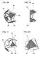
- FIG 2A to FIG 2D show examples in which a decorative pattern is formed on the inner surface of the cover 30.
- a plurality of decorative lines are formed in each of an upper left corner region R1, an upper right corner region R2, a lower left corner region R3 and a lower right corner region R4 of the inner peripheral surface of the cover 30. These decorative lines extend in the front-rear direction (axial direction) of the cover 30. The decorative lines are spaced apart from each other at predetermined intervals in the circumferential direction of the cover 30.
- the decorative lines are formed of rib-like protrusions 61, so that bumps and dips can be provided in each of the regions R1 to R4 as the decorative patterns.
- the decorative patterns are provided on the molding surface of a molding die, and then, when the cover 30 is molded using the molding die, the protrusions 61 are formed in each of the regions R1 to R4. Because the cover 30 is transparent, when the cover 30 is viewed from the outer side, the decorative patterns (bums and dips) can be seen through the outer side as shown in FIG 2A and FIG 2B .
- the decorative patterns are formed by bumps and dips at the inner surface of the transparent cover 30 such that heat of the metal case 20 is only transmitted to the cover 30 at parts of the cover 30 which directly contact the hammer case 20, i.e. the heat is transmitted via the decorative patterns only by the bumps. However, there is no transmission of the heat by the dips. Thus, the transmission of the heat between the hammer case 20 and the cover 30 is reduced at the parts of the cover 30 where the decorative patterns are provided. Therefore, the operability of the power tool is improved.
- the decorative patterns improve the appearance of the impact driver 1 to enhance the decorativeness of the impact driver 1. Further, the decorative patterns indicate the parts of the cover 30 with less heat transmission due to its decorativeness. Thus, the user can only grip these parts such that the operability of the power tool is improved.
- the bumps and dips are provided as the decorative patterns to enhance a sense of depth.
- a second embodiment of the present invention will be described with reference to FIG 3A to FIG 3D .
- a cover 30A can be attached to the impact driver 1 (see FIG 1 ) instead of the cover 30 according to the first embodiment.
- a plurality of decorative lines are formed in each of an upper left corner region R11, an upper right corner region R12, a lower left corner region R13 and a lower right corner region R14 of the inner peripheral surface of the cover 30A. These decorative lines extend in the front-rear direction of the cover 30A as in the case of the first embodiment.
- the height of protrusion of each of rib-like protrusions 62 is reduced to a degree to which the presence of the decorative lines may be recognized as compared with the height of protrusion of each of the protrusions 61 according to the first embodiment.
- the interval between the adjacent protrusions 62 (decorative lines) is wider than the interval between the adjacent protrusions 61 (decorative lines). Therefore, the decorative patterns (bumps and dips) different from those of the first embodiment can be formed in the regions R11 to R14. In the present embodiment as well, as shown in FIG 3A and FIG 3B , the decorative patterns (bumps and dips) can be seen through the outer side of the cover 30A.
- the bumps and dips different from those of the first embodiment are provided as the decorative patterns to enhance a sense of depth different from that of the first embodiment.
- the decorative patterns are formed by bumps and dips at the inner surface of the transparent cover 30A such that heat of the metal case 20 is only transmitted to the cover 30A at parts of the cover 30A which directly contact the hammer case 20, i.e. the heat is transmitted via the decorative patterns only by the bumps. However, there is no transmission of the heat by the dips. Thus, the transmission of the heat between the hammer case 20 and the cover 30A is reduced at the parts of the cover 30A where the decorative patterns are provided. Therefore, the operability of the power tool is improved.
- the decorative patterns indicate the parts of the cover 30A with less heat transmission due to its decorativeness. Thus, the user can only grip these parts such that the operability of the power tool is improved.
- a third embodiment of the present invention will be described with reference to FIG 4A to FIG 4D .
- a cover 30B may also be attached to the impact driver 1 as in the case of that of the second embodiment.
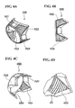
- a plurality of decorative lines are formed in each of an upper left corner region R21, an upper right corner region R22, a lower left corner region R23 and a lower right corner region R24 of the inner peripheral surface of the cover 30B. These decorative lines extend in the circumferential direction of the cover 30B, different from those of the first and second embodiments.
- each decorative line is formed of a protrusion 63 that is inclined upward so that the height of the protrusion at the rear portion of the cover 30B is higher than the height of the protrusion at the front portion of the cover 30B. Furthermore, the decorative lines are provided adjacent to each other in the front-rear direction of the cover 30B.
- the protrusions 63 can be formed in each of the regions R21 to R24. As shown in FIG 4A and FIG 4B , the decorative patterns (bumps and dips) formed of the plurality of protrusions 63 can be seen through the outer side of the cover 30B.
- the direction in which the decorative lines extend is set in the circumferential direction of the cover 30B to enhance a sense of depth different from those of the first and second embodiments.
- the decorative patterns are formed by bumps and dips at the inner surface of the transparent cover 30B such that heat of the metal case 20 is only transmitted to the cover 30B at parts of the cover 30B which directly contact the hammer case 20, i.e. the heat is transmitted via the decorative patterns only by the bumps. However, there is no transmission of the heat by the dips. Thus, the transmission of the heat between the hammer case 20 and the cover 30B is reduced at the parts of the cover 30B where the decorative patterns are provided. Therefore, the operability of the power tool is improved.
- the decorative patterns indicate the parts of the cover 30B with less heat transmission due to its decorativeness. Thus, the user can only grip these parts such that the operability of the power tool is improved.
- a fourth embodiment of the present invention will be described with reference to FIG 5A to FIG 5D .
- a cover 30C can also be attached to the impact driver 1 as in the case of those of the second and third embodiments.
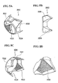
- Fine bump and dip patterns are formed in each of an upper left corner region R31, an upper right corner region R32, a lower left corner region R33 and a lower right corner region R34 of the inner peripheral surface of the cover 30C.
- the bump and dip patterns are shown by oblique lines.
- a grain pattern can be formed in each of the regions R31 to R34. In the present embodiment as well, the grain patterns can be seen through the outer side of the cover 30C.
- tiny bumps and dips are repeated by the grain patterns to provide a sense that the decorative patterns are raised, so a sense of depth may be provided.
- the decorative patterns are formed of tiny bumps and dips.
- the decorative patterns are formed by bumps and dips at the inner surface of the transparent cover 30C such that heat of the metal case 20 is only transmitted to the cover 30C at parts of the cover 30C which directly contact the hammer case 20, i.e. the heat is transmitted via the decorative patterns only by the bumps. However, there is no transmission of the heat by the dips. Thus, the transmission of the heat between the hammer case 20 and the cover 30C is reduced at the parts of the cover 30C where the decorative patterns are provided. Therefore, the operability of the power tool is improved.
- the decorative patterns indicate the parts of the cover 30C with less heat transmission due to its decorativeness. Thus, the user can only grip these parts such that the operability of the power tool is improved.
- the aspect of the present invention is not limited to the above described embodiments; part of the components may be appropriately modified without departing from the scope of the present invention.
- the number of the decorative lines, the interval of the adj acent decorative lines and the height of protrusion of each rib-like protrusion may be changed to appropriate ones different from those of the first and second embodiments.
- each decorative line may be formed of a protrusion that is inclined downward so that the height of the protrusion at the rear portion of the cover 30B is lower than the height of the protrusion at the front portion of the cover 30B.
- the decorative patterns are formed in each of the upper and lower left corner regions and upper and lower right corner regions of the inner peripheral surface of the cover; instead, the decorative patterns may be formed over all around the inner surface of the cover.
- the decorative pattern may be an appropriate combination of the bumps and dips according to the first to fourth embodiments.
- a paint may be applied onto the recesses or protrusions of the bumps and dips to be colored or the bumps and dips may be formed of metal plating.
- a cover may be attached to a portion, exposed through the body portion 11, on the front outer periphery of the hammer case 20.
- the protrusions forming the bumps and dips of the decorative patterns are formed on the transparent cover 30, 30A, 30B, 30C made of synthetic resin.
- the protrusions could be formed on the metal hammer case 20. However, this would be more expensive.
- the protrusions do not only reduce the heat transmission, but also provide a damping effect in case that an impact is applied to the cover of the power tool, i.e. the protection of the hammer case 20 is improved.
Landscapes
- Engineering & Computer Science (AREA)
- Mechanical Engineering (AREA)
- Portable Power Tools In General (AREA)
- Moulds For Moulding Plastics Or The Like (AREA)
- Percussive Tools And Related Accessories (AREA)
Abstract
Description
- The present invention relates to an electric power tool in which a metal front housing that accommodates a driving mechanism is assembled to the front of a main housing that accommodates a motor and the outer periphery of the front housing is protected by a cylindrical transparent cover made of synthetic resin.
- Japanese Patent Application Publication No.
2009-220272 JP-A-2009-220272 JP-A-2009-220272 - Incidentally, the above electric power tool has a limited decorative portion, so it is not easy to accentuate its decorativeness. For this reason, an existing electric power tool has a poor appearance, and may not have a good decorativeness and a good operability.
- The object of the present invention is to provide an electric power tool that has a high decorativeness and an improved operability.
- A first aspect of the present invention provides an electric power tool including a main housing that accommodates a motor, a metal front housing that is assembled to a front of the main housing and that accommodates a driving mechanism, an output shaft that protrudes from a distal end of the front housing, and a cylindrical transparent cover that protects an outer periphery of the front housing and that is made of synthetic resin, wherein a decorative pattern is formed on an inner surface of the transparent cover.
- A second aspect of the present invention provides such a feature that, in the first aspect, the decorative pattern is formed of bumps and dips on the inner surface.
- With the electric power tool according to the first aspect of the present invention, the decorative pattern can be seen through an outer side of the transparent cover. Thus, the decorative pattern improves the appearance of the electric power tool to enhance the decorativeness of the electric power tool. Further, the decorative pattern indicates parts of the cover with less heat transmission. Thus, the user can only grip these parts such that the operability of the power tool is improved.
- According to the second aspect of the present invention, a sense of depth is enhanced by the bumps and dips.
-
-
FIG 1 is a side view of an impact driver according to a first embodiment of the present invention. -
FIG 2A is an overall perspective view of a cover according to the first embodiment. -
FIG 2B is a side view of the cover. -
FIG 2C is a view that shows a state where decorative patterns are formed on the inner surface of the cover. -
FIG 2D is a partially enlarged view ofFIG 2C . -
FIG 3A is an overall perspective view of a cover according to a second embodiment. -
FIG 3B is a side view of the cover. -
FIG 3C is a view that shows a state where decorative patterns are formed on the inner surface of the cover. -
FIG 3D is a partially enlarged view ofFIG 3C . -
FIG 4A is an overall perspective view of a cover according to a third embodiment. -
FIG 4B is a side view of the cover. -
FIG 4C is a view that shows a state where decorative patterns are formed on the inner surface of the cover. -
FIG 4D is a partially enlarged view ofFIG 4C . -
FIG 5A is an overall perspective view of a cover according to a fourth embodiment. -
FIG 5B is a side view of the cover. -
FIG 5C is a view that shows a state where decorative patterns are formed on the inner surface of the cover. -
FIG 5D is a partially enlarged view ofFIG 5C . - A first embodiment of the present invention will be described with reference to
FIG 1 to FIG 2D . An impact driver 1 shown inFIG 1 includes amain housing 10, ahammer case 20, acover 30, abumper 40 and ahook 50. - The
main housing 10 is formed by assembling right and left half housings made of resin. Themain housing 10 has abody portion 11, ahandle portion 12 and a batterypack loading portion 13. Thebody portion 11 is formed in a cylindrical shape and extends in the front-rear direction (horizontal direction inFIG 1 ) of the impact driver 1. A motor (not shown) is accommodated inside thebody portion 11. - As shown in
FIG 1 , thehandle portion 12 is continuously provided from thebody portion 11 so as to form a substantially T shape in side view of the impact driver 1. A switch (not shown) having atrigger 14 is accommodated inside thehandle portion 12. Abattery pack 15 is detachably loaded at the batterypack loading portion 13. The battery pack 15 feeds power to the motor. Note that the impact driver 1 is an example of the electric power tool according to the aspect of the present invention. - The
hammer case 20 is made of metal (for example, aluminum), and is assembled to the front (left side inFIG 1 ) of thebody portion 11. A striking mechanism (not shown) and ananvil 21 are accommodated inside thehammer case 20. Theanvil 21 protrudes from the distal end surface of thehammer case 20. Theanvil 21 is rotatably supported inside thehammer case 20 by a bearing. Achuck 22 is provided at the distal end of theanvil 21. A distal end tool may be attached to thechuck 22. The striking mechanism converts rotation of the motor to rotational striking force and then transmits the rotational striking force to the distal end tool. Note that thehammer case 20 is an example of the front housing according to the aspect of the present invention, theanvil 21 is an example of the output shaft according to the aspect of the present invention, and the striking mechanism is an example of the driving mechanism according to the aspect of the present invention. - The
cover 30 is made of a transparent synthetic resin and is formed in a cylindrical shape. Thecover 30 is attached to a portion, from which the hammer case is exposed through thebody portion 11, on the front outer periphery of thehammer case 20. As will be described later, decorative patterns are formed on the inner surface of thecover 30. Thebumper 40 is made of synthetic rubber and is formed in a ring shape. Thebumper 40 is assembled to the front end of thecover 30, and is attached to the exposed portion. In a state where thebumper 40 is assembled to the front end of thecover 30, the outer peripheral surface of thebumper 40 is continuous with the outer peripheral surface of thecover 30, and thecover 30 and thebumper 40 prevent the front outer periphery of thehammer case 20 from being exposed. By so doing, thecover 30 and thebumper 40 protect the front outer periphery. Note that thecover 30 is an example of the transparent cover according to the aspect of the present invention. - The
hook 50 is attached to the right side surface (in front view of the impact driver 1) of the batterypack loading portion 13 using ascrew 51. Thehook 50 is formed by bending a metal plate into a substantially U shape in front view and rear view of the impact driver 1. Thehook 50 allows the impact driver 1 to be suspended from a worker's belt. -
FIG 2A to FIG 2D show examples in which a decorative pattern is formed on the inner surface of thecover 30. In the present embodiment, a plurality of decorative lines are formed in each of an upper left corner region R1, an upper right corner region R2, a lower left corner region R3 and a lower right corner region R4 of the inner peripheral surface of thecover 30. These decorative lines extend in the front-rear direction (axial direction) of thecover 30. The decorative lines are spaced apart from each other at predetermined intervals in the circumferential direction of thecover 30. - As shown in
FIG 2D , the decorative lines are formed of rib-like protrusions 61, so that bumps and dips can be provided in each of the regions R1 to R4 as the decorative patterns. In the present embodiment, the decorative patterns are provided on the molding surface of a molding die, and then, when thecover 30 is molded using the molding die, theprotrusions 61 are formed in each of the regions R1 to R4. Because thecover 30 is transparent, when thecover 30 is viewed from the outer side, the decorative patterns (bums and dips) can be seen through the outer side as shown inFIG 2A and FIG 2B . - The decorative patterns are formed by bumps and dips at the inner surface of the
transparent cover 30 such that heat of themetal case 20 is only transmitted to thecover 30 at parts of thecover 30 which directly contact thehammer case 20, i.e. the heat is transmitted via the decorative patterns only by the bumps. However, there is no transmission of the heat by the dips. Thus, the transmission of the heat between thehammer case 20 and thecover 30 is reduced at the parts of thecover 30 where the decorative patterns are provided. Therefore, the operability of the power tool is improved. - In the impact driver 1 according to the first embodiment, as described above, when the
cover 30 is viewed from the outer side, the decorative patterns can be seen through the outer side. Thus, the decorative patterns improve the appearance of the impact driver 1 to enhance the decorativeness of the impact driver 1. Further, the decorative patterns indicate the parts of thecover 30 with less heat transmission due to its decorativeness. Thus, the user can only grip these parts such that the operability of the power tool is improved. - In addition, the bumps and dips are provided as the decorative patterns to enhance a sense of depth.
- A second embodiment of the present invention will be described with reference to
FIG 3A to FIG 3D . Here, the description of the same components to those of the first embodiment is omitted. Acover 30A can be attached to the impact driver 1 (seeFIG 1 ) instead of thecover 30 according to the first embodiment. A plurality of decorative lines are formed in each of an upper left corner region R11, an upper right corner region R12, a lower left corner region R13 and a lower right corner region R14 of the inner peripheral surface of thecover 30A. These decorative lines extend in the front-rear direction of thecover 30A as in the case of the first embodiment. - In the present embodiment, different from the first embodiment, the height of protrusion of each of rib-
like protrusions 62 is reduced to a degree to which the presence of the decorative lines may be recognized as compared with the height of protrusion of each of theprotrusions 61 according to the first embodiment. In addition, the interval between the adjacent protrusions 62 (decorative lines) is wider than the interval between the adjacent protrusions 61 (decorative lines). Therefore, the decorative patterns (bumps and dips) different from those of the first embodiment can be formed in the regions R11 to R14. In the present embodiment as well, as shown inFIG 3A and FIG 3B , the decorative patterns (bumps and dips) can be seen through the outer side of thecover 30A. - In the second embodiment, the bumps and dips different from those of the first embodiment are provided as the decorative patterns to enhance a sense of depth different from that of the first embodiment.
- The decorative patterns are formed by bumps and dips at the inner surface of the
transparent cover 30A such that heat of themetal case 20 is only transmitted to thecover 30A at parts of thecover 30A which directly contact thehammer case 20, i.e. the heat is transmitted via the decorative patterns only by the bumps. However, there is no transmission of the heat by the dips. Thus, the transmission of the heat between thehammer case 20 and thecover 30A is reduced at the parts of thecover 30A where the decorative patterns are provided. Therefore, the operability of the power tool is improved. - Further, the decorative patterns indicate the parts of the
cover 30A with less heat transmission due to its decorativeness. Thus, the user can only grip these parts such that the operability of the power tool is improved. - A third embodiment of the present invention will be described with reference to
FIG 4A to FIG 4D . Here, the description of the same components to those of the first and second embodiments is omitted. Acover 30B may also be attached to the impact driver 1 as in the case of that of the second embodiment. A plurality of decorative lines are formed in each of an upper left corner region R21, an upper right corner region R22, a lower left corner region R23 and a lower right corner region R24 of the inner peripheral surface of thecover 30B. These decorative lines extend in the circumferential direction of thecover 30B, different from those of the first and second embodiments. - In the present embodiment, as shown in
FIG 4D , each decorative line is formed of aprotrusion 63 that is inclined upward so that the height of the protrusion at the rear portion of thecover 30B is higher than the height of the protrusion at the front portion of thecover 30B. Furthermore, the decorative lines are provided adjacent to each other in the front-rear direction of thecover 30B. In the present embodiment as well, as in the case of the first and second embodiments, when thecover 30B is molded, theprotrusions 63 can be formed in each of the regions R21 to R24. As shown inFIG 4A and FIG 4B , the decorative patterns (bumps and dips) formed of the plurality ofprotrusions 63 can be seen through the outer side of thecover 30B. - In the third embodiment, different from the first and second embodiments, the direction in which the decorative lines extend is set in the circumferential direction of the
cover 30B to enhance a sense of depth different from those of the first and second embodiments. - The decorative patterns are formed by bumps and dips at the inner surface of the
transparent cover 30B such that heat of themetal case 20 is only transmitted to thecover 30B at parts of thecover 30B which directly contact thehammer case 20, i.e. the heat is transmitted via the decorative patterns only by the bumps. However, there is no transmission of the heat by the dips. Thus, the transmission of the heat between thehammer case 20 and thecover 30B is reduced at the parts of thecover 30B where the decorative patterns are provided. Therefore, the operability of the power tool is improved. - Further, the decorative patterns indicate the parts of the
cover 30B with less heat transmission due to its decorativeness. Thus, the user can only grip these parts such that the operability of the power tool is improved. - A fourth embodiment of the present invention will be described with reference to
FIG 5A to FIG 5D . Here, the description of the same components to those of the first to third embodiments is omitted. Acover 30C can also be attached to the impact driver 1 as in the case of those of the second and third embodiments. Fine bump and dip patterns (grain patterns) are formed in each of an upper left corner region R31, an upper right corner region R32, a lower left corner region R33 and a lower right corner region R34 of the inner peripheral surface of thecover 30C. InFIG 5A to FIG 5D , the bump and dip patterns are shown by oblique lines. - In the present embodiment, when the
cover 30C is molded using a molding die in which bumps and dips are formed, a grain pattern can be formed in each of the regions R31 to R34. In the present embodiment as well, the grain patterns can be seen through the outer side of thecover 30C. - In the fourth embodiment, tiny bumps and dips are repeated by the grain patterns to provide a sense that the decorative patterns are raised, so a sense of depth may be provided. In addition, different from the first to third embodiments, the decorative patterns are formed of tiny bumps and dips.
- The decorative patterns are formed by bumps and dips at the inner surface of the
transparent cover 30C such that heat of themetal case 20 is only transmitted to thecover 30C at parts of thecover 30C which directly contact thehammer case 20, i.e. the heat is transmitted via the decorative patterns only by the bumps. However, there is no transmission of the heat by the dips. Thus, the transmission of the heat between thehammer case 20 and thecover 30C is reduced at the parts of thecover 30C where the decorative patterns are provided. Therefore, the operability of the power tool is improved. - Further, the decorative patterns indicate the parts of the
cover 30C with less heat transmission due to its decorativeness. Thus, the user can only grip these parts such that the operability of the power tool is improved. - The aspect of the present invention is not limited to the above described embodiments; part of the components may be appropriately modified without departing from the scope of the present invention. For example, as in the case of the first and second embodiments, when the decorative patterns are formed of the decorative lines, the number of the decorative lines, the interval of the adj acent decorative lines and the height of protrusion of each rib-like protrusion may be changed to appropriate ones different from those of the first and second embodiments.
- In addition, as in the case of the above described third embodiment, when the decorative lines are formed of the upward-
inclined protrusions 63, the angle of upward inclination may be appropriately changed. Furthermore, different from the third embodiment, each decorative line may be formed of a protrusion that is inclined downward so that the height of the protrusion at the rear portion of thecover 30B is lower than the height of the protrusion at the front portion of thecover 30B. - In addition, in the above described first to fourth embodiments, the decorative patterns are formed in each of the upper and lower left corner regions and upper and lower right corner regions of the inner peripheral surface of the cover; instead, the decorative patterns may be formed over all around the inner surface of the cover. Furthermore, the decorative pattern may be an appropriate combination of the bumps and dips according to the first to fourth embodiments. In addition, a paint may be applied onto the recesses or protrusions of the bumps and dips to be colored or the bumps and dips may be formed of metal plating. Furthermore, different from the first to fourth embodiments, without providing the
bumper 40, a cover may be attached to a portion, exposed through thebody portion 11, on the front outer periphery of thehammer case 20. - Further, the protrusions forming the bumps and dips of the decorative patterns are formed on the
transparent cover metal hammer case 20. However, this would be more expensive. - Furthermore, the protrusions (bumps and dips) do not only reduce the heat transmission, but also provide a damping effect in case that an impact is applied to the cover of the power tool, i.e. the protection of the
hammer case 20 is improved. - It is explicitly stated that all features disclosed in the description and/or the claims are intended to be disclosed separately and independently from each other for the purpose of original disclosure as well as for the purpose of restricting the claimed invention independent of the composition of the features in the embodiments and/or the claims. It is explicitly stated that all value ranges or indications of groups of entities disclose every possible intermediate value or intermediate entity for the purpose of original disclosure as well as for the purpose of restricting the claimed invention, in particular as limits of value ranges.
Claims (9)
- An electric power tool in which a metal front housing (20) that accommodates a driving mechanism is assembled to a front of a main housing (10) that accommodates a motor, an output shaft (21) is protruded from a distal end of the front housing (20), and an outer periphery of the front housing (20) is protected by a cylindrical transparent cover (30) made of synthetic resin, characterized in that:a decorative pattern is formed on an inner surface of the transparent cover (30).
- The electric power tool according to claim 1, wherein the decorative pattern is formed of bumps and dips on the inner surface.
- The electric power tool according to claim 2, wherein the bumps and dips are formed of a plurality of decorative lines that extend in a front-rear direction of the transparent cover (30) at a predetermined interval in a circumferential direction of the transparent cover (30).
- The electric power tool according to claim 3, wherein the decorative lines are each formed of a rib-like protrusion (61, 62)
- The electric power tool according to claim 2, wherein the bumps and dips are formed of a plurality of decorative lines that are adjacent to each other in a front-rear direction of the transparent cover (30) and that extend in a circumferential direction of the transparent cover (30).
- The electric power tool according to claim 5, wherein the decorative lines are each formed of a protrusion (63) that is inclined upward so that a height of the protrusion (63) at a rear portion of the transparent cover (30) is higher than a height of the protrusion (63) at a front portion of the transparent cover (30) or a protrusion (63) that is inclined downward so that the height of the protrusion (63) at the rear portion of the transparent cover (30) is lower than the height of the protrusion (63) at the front portion of the transparent cover (30).
- The electric power tool according to claim 2, wherein the bumps and dips are formed of a grain pattern.
- The electric power tool according to any one of claims 1 to 7, wherein the decorative pattern is formed in each of upper and lower left corner regions (R1, R3, R11, R13, R21, R23, R31, R33) and upper and lower right corner regions (R2, R4, R12, R14, R22, R24, R32, R34) of an inner peripheral surface of the transparent cover (30).
- The electric power tool according to any one of claims 1 to 7, wherein the decorative pattern is formed over a whole inner peripheral surface of the transparent cover (30).
Applications Claiming Priority (1)
| Application Number | Priority Date | Filing Date | Title |
|---|---|---|---|
| JP2010185347A JP5475592B2 (en) | 2010-08-20 | 2010-08-20 | Electric tool |
Publications (3)
| Publication Number | Publication Date |
|---|---|
| EP2428325A2 true EP2428325A2 (en) | 2012-03-14 |
| EP2428325A3 EP2428325A3 (en) | 2014-03-26 |
| EP2428325B1 EP2428325B1 (en) | 2015-02-25 |
Family
ID=45044822
Family Applications (1)
| Application Number | Title | Priority Date | Filing Date |
|---|---|---|---|
| EP11176556.6A Active EP2428325B1 (en) | 2010-08-20 | 2011-08-04 | Electric power tool |
Country Status (5)
| Country | Link |
|---|---|
| US (1) | US8910728B2 (en) |
| EP (1) | EP2428325B1 (en) |
| JP (1) | JP5475592B2 (en) |
| CN (1) | CN202357135U (en) |
| RU (1) | RU2011134914A (en) |
Cited By (1)
| Publication number | Priority date | Publication date | Assignee | Title |
|---|---|---|---|---|
| US12233523B2 (en) | 2020-12-07 | 2025-02-25 | Black & Decker Inc. | Power tool with multiple modes of operation and ergonomic handgrip |
Families Citing this family (33)
| Publication number | Priority date | Publication date | Assignee | Title |
|---|---|---|---|---|
| USD679160S1 (en) * | 2010-11-26 | 2013-04-02 | Makita Corporation | Portable electric driver |
| USD678024S1 (en) * | 2011-01-18 | 2013-03-19 | Hitachi Koki Co., Ltd. | Portable electric driver |
| USD672627S1 (en) * | 2011-04-07 | 2012-12-18 | Makita Corporation | Portable electric driver |
| USD677137S1 (en) * | 2011-08-10 | 2013-03-05 | Makita Corporation | Portable electric driver |
| USD679161S1 (en) * | 2011-09-06 | 2013-04-02 | Makita Corporation | Portable electric driver |
| USD691444S1 (en) * | 2012-07-19 | 2013-10-15 | Black & Decker Inc. | Impact driver |
| USD719424S1 (en) * | 2012-07-31 | 2014-12-16 | Makita Corporation | Caulking gun |
| JP6032400B2 (en) * | 2012-08-15 | 2016-11-30 | 日立工機株式会社 | Chainsaw |
| US9950418B2 (en) * | 2012-12-25 | 2018-04-24 | Makita Corporation | Impact tool |
| JP6085225B2 (en) | 2013-06-27 | 2017-02-22 | 株式会社マキタ | Screw tightening electric tool |
| USD725981S1 (en) | 2013-10-29 | 2015-04-07 | Black & Decker Inc. | Screwdriver with nosepiece |
| US20150151424A1 (en) | 2013-10-29 | 2015-06-04 | Black & Decker Inc. | Power tool with ergonomic handgrip |
| JP1532654S (en) * | 2015-03-31 | 2015-09-07 | ||
| USD840032S1 (en) * | 2017-03-29 | 2019-02-05 | Stryker Corporation | Surgical drill |
| US10531724B2 (en) * | 2017-03-29 | 2020-01-14 | Tti (Macao Commercial Offshore) Limited | Belt clip for power tool |
| USD928841S1 (en) * | 2019-04-10 | 2021-08-24 | Signode Industrial Group Llc | Inflator |
| USD929837S1 (en) * | 2019-11-13 | 2021-09-07 | Learning Resources, Inc. | Toy power drill |
| USD918270S1 (en) * | 2019-12-25 | 2021-05-04 | Ningbo Mutian Electric Co., Ltd. | Tire Inflator |
| USD917575S1 (en) * | 2020-08-28 | 2021-04-27 | Shenzhen Chenguo Technology Co., Ltd. | Handheld tire inflator |
| USD978199S1 (en) * | 2021-03-24 | 2023-02-14 | Vector Products, Inc. | Inflator |
| JP1722417S (en) * | 2022-01-06 | 2022-08-15 | Portable electric driver body | |
| JP1722418S (en) * | 2022-01-06 | 2022-08-15 | Portable electric driver body | |
| JP1722419S (en) * | 2022-01-06 | 2022-08-15 | Portable electric driver body | |
| JP1722416S (en) * | 2022-01-06 | 2022-08-15 | Portable electric driver body | |
| USD1031031S1 (en) | 2022-01-14 | 2024-06-11 | Stryker Corporation | Surgical handpiece |
| USD1028229S1 (en) | 2022-01-14 | 2024-05-21 | Stryker Corporation | Surgical handpiece |
| USD1028228S1 (en) | 2022-01-14 | 2024-05-21 | Stryker Corporation | Surgical handpiece |
| USD1028230S1 (en) | 2022-01-14 | 2024-05-21 | Stryker Corporation | Surgical handpiece |
| USD1073430S1 (en) * | 2022-07-22 | 2025-05-06 | Navac Inc. | Power tube expander |
| USD1056372S1 (en) * | 2024-03-24 | 2024-12-31 | Muhong Luo | Electric spin scrubber |
| USD1059424S1 (en) * | 2024-07-19 | 2025-01-28 | Guangzhou Bulaidi Trading Co., Ltd. | Inflator |
| USD1099978S1 (en) * | 2024-08-30 | 2025-10-28 | Shenzhen Keenpower New Energy Technology Co., Ltd. | Electric air pump |
| USD1111059S1 (en) * | 2024-11-12 | 2026-02-03 | E. Mishan & Sons, Inc. | Inflator |
Citations (1)
| Publication number | Priority date | Publication date | Assignee | Title |
|---|---|---|---|---|
| JP2009220272A (en) | 2009-07-07 | 2009-10-01 | Hitachi Koki Co Ltd | Power tool |
Family Cites Families (32)
| Publication number | Priority date | Publication date | Assignee | Title |
|---|---|---|---|---|
| US2207269A (en) * | 1938-11-16 | 1940-07-09 | Henry T Schiff | Nonslip shaving implement |
| GB1252821A (en) | 1969-06-23 | 1971-11-10 | ||
| DE3673489D1 (en) * | 1985-10-11 | 1990-09-20 | Swarovski & Co | DECORATION BODY IN GLASS. |
| JPS62184905U (en) * | 1986-05-12 | 1987-11-25 | ||
| US5025970A (en) * | 1990-03-20 | 1991-06-25 | National Carpet Equipment Inc. | Protective sleeve for carpet tacking gun |
| JP3047193U (en) * | 1997-09-17 | 1998-03-31 | 株式会社中日ステンドアート | Room |
| US5992540A (en) * | 1998-03-06 | 1999-11-30 | Snap-On Tools Company | Air ratchet hand tool with thermoplastic jacket |
| JP2002337101A (en) | 2001-05-15 | 2002-11-27 | Makita Corp | Jigsaw |
| JP3740694B2 (en) * | 2002-02-22 | 2006-02-01 | 日立工機株式会社 | Electric tool |
| US6729414B2 (en) * | 2002-07-16 | 2004-05-04 | Black & Decker Inc. | Cordless drill with metal housing |
| CN1305013C (en) * | 2002-11-28 | 2007-03-14 | 日立工机株式会社 | Portable tool having cover and label to be stuck on the portable tool for identification |
| JP4314817B2 (en) * | 2002-11-28 | 2009-08-19 | 日立工機株式会社 | Portable tool cover, combination of portable tool and portable tool cover, and combination of portable tool, portable tool cover and portable tool seat |
| JP4363056B2 (en) * | 2003-02-20 | 2009-11-11 | 日立工機株式会社 | Method for printing portable tool sheet and method for providing portable tool sheet |
| JP2005144611A (en) * | 2003-11-17 | 2005-06-09 | Makita Corp | Bumper for power tool and power tool |
| JP4004482B2 (en) * | 2004-03-30 | 2007-11-07 | 栗三 笠松 | Portable power tool and waterproof cover |
| JP4396447B2 (en) * | 2004-08-20 | 2010-01-13 | 日立工機株式会社 | Electric tool |
| DE202005018772U1 (en) | 2005-12-01 | 2006-03-09 | Hans Einhell Ag | Hand guided rotation tool e.g. hand drill, has accommodating and allocating device arranged at external area in end section of tool to accommodate or allocate magazines, where device is made up of transparent material |
| USD534779S1 (en) * | 2006-05-24 | 2007-01-09 | Mobiletron Electronics Co., Ltd. | Electric handtool |
| DE102006029625A1 (en) | 2006-06-28 | 2008-01-03 | Robert Bosch Gmbh | Suction device of an electric hand tool and electric hand tool with suction device |
| USD560990S1 (en) * | 2006-07-21 | 2008-02-05 | Robert Bosch Gmbh | Impact drill |
| JP2008057899A (en) * | 2006-09-01 | 2008-03-13 | Hitachi Appliances Inc | refrigerator |
| JP4962902B2 (en) * | 2006-10-13 | 2012-06-27 | 日立工機株式会社 | Portable belt polishing machine |
| WO2008133339A1 (en) | 2007-04-23 | 2008-11-06 | Hitachi Koki Co., Ltd. | Electrical power tool |
| USD565375S1 (en) * | 2007-05-03 | 2008-04-01 | Black & Decker Inc. | Impact driver |
| JP2009083058A (en) * | 2007-09-28 | 2009-04-23 | Hitachi Koki Co Ltd | Electric tool |
| JP5229538B2 (en) * | 2008-03-31 | 2013-07-03 | 日立工機株式会社 | Portable cutting tool |
| JP4677531B2 (en) * | 2008-08-08 | 2011-04-27 | 株式会社ナカヤ | Dust collecting adapter for rotary cutting machine |
| JP5352153B2 (en) * | 2008-08-11 | 2013-11-27 | 株式会社マキタ | Rechargeable power tool |
| JP3153141U (en) * | 2009-05-26 | 2009-08-27 | 史郎 宮川 | Dust absorber |
| USD628038S1 (en) * | 2009-08-19 | 2010-11-30 | Hitachi Koki Co., Ltd. | Portable electric driver |
| JP5448884B2 (en) * | 2010-01-28 | 2014-03-19 | 株式会社マキタ | Impact tool |
| USD656804S1 (en) * | 2011-05-17 | 2012-04-03 | Black & Decker Inc. | Impact driver |
-
2010
- 2010-08-20 JP JP2010185347A patent/JP5475592B2/en active Active
-
2011
- 2011-07-11 US US13/180,026 patent/US8910728B2/en active Active
- 2011-08-04 EP EP11176556.6A patent/EP2428325B1/en active Active
- 2011-08-19 RU RU2011134914/02A patent/RU2011134914A/en not_active Application Discontinuation
- 2011-08-19 CN CN2011203106245U patent/CN202357135U/en not_active Expired - Lifetime
Patent Citations (1)
| Publication number | Priority date | Publication date | Assignee | Title |
|---|---|---|---|---|
| JP2009220272A (en) | 2009-07-07 | 2009-10-01 | Hitachi Koki Co Ltd | Power tool |
Cited By (1)
| Publication number | Priority date | Publication date | Assignee | Title |
|---|---|---|---|---|
| US12233523B2 (en) | 2020-12-07 | 2025-02-25 | Black & Decker Inc. | Power tool with multiple modes of operation and ergonomic handgrip |
Also Published As
| Publication number | Publication date |
|---|---|
| US20120043102A1 (en) | 2012-02-23 |
| RU2011134914A (en) | 2013-02-27 |
| JP5475592B2 (en) | 2014-04-16 |
| EP2428325A3 (en) | 2014-03-26 |
| CN202357135U (en) | 2012-08-01 |
| US8910728B2 (en) | 2014-12-16 |
| EP2428325B1 (en) | 2015-02-25 |
| JP2012040659A (en) | 2012-03-01 |
Similar Documents
| Publication | Publication Date | Title |
|---|---|---|
| EP2428325B1 (en) | Electric power tool | |
| EP2332697B1 (en) | Hook for electric power tools and electric power tool equipped with the hook | |
| CA2830632C (en) | Handle protector for a hand tool | |
| USD566509S1 (en) | Ball peen hammer with flat top head | |
| JP2016165783A (en) | Impact tool | |
| US20120085560A1 (en) | Electric power tool suspending attachment and electric power tool equipped with the same | |
| USD468987S1 (en) | Multi-function tool for use by divers | |
| USD525935S1 (en) | Charging cradle for electronic device | |
| JP2012139763A (en) | Power tool | |
| EP2397202A3 (en) | Playground equipment | |
| US20140050963A1 (en) | Electric working machine and electric working machine system | |
| USD645722S1 (en) | Multi-function pocket tool | |
| USD533423S1 (en) | Electric impact driver | |
| CN203327090U (en) | Multifunctional mobile phone protection shell | |
| US20130220659A1 (en) | Oscillating rotary electric power tool | |
| KR101335762B1 (en) | Cell phone case | |
| US10040672B2 (en) | Transmitting/receiving device | |
| JP2017144523A5 (en) | ||
| US20150352706A1 (en) | Portable Work Tool | |
| CA2476068A1 (en) | Handle assembly for power tool | |
| USD594724S1 (en) | Portable electric round saw | |
| US20110127057A1 (en) | Portable power tool, particularly cordless screwdriver or cordless drill | |
| JP4645332B2 (en) | Portable electric circular saw | |
| JP2011136384A (en) | Hand-held type power tool and method for manufacturing housing | |
| JP2007231465A (en) | Hand protector for beating work |
Legal Events
| Date | Code | Title | Description |
|---|---|---|---|
| AK | Designated contracting states |
Kind code of ref document: A2 Designated state(s): AL AT BE BG CH CY CZ DE DK EE ES FI FR GB GR HR HU IE IS IT LI LT LU LV MC MK MT NL NO PL PT RO RS SE SI SK SM TR |
|
| AX | Request for extension of the european patent |
Extension state: BA ME |
|
| PUAI | Public reference made under article 153(3) epc to a published international application that has entered the european phase |
Free format text: ORIGINAL CODE: 0009012 |
|
| PUAL | Search report despatched |
Free format text: ORIGINAL CODE: 0009013 |
|
| AK | Designated contracting states |
Kind code of ref document: A3 Designated state(s): AL AT BE BG CH CY CZ DE DK EE ES FI FR GB GR HR HU IE IS IT LI LT LU LV MC MK MT NL NO PL PT RO RS SE SI SK SM TR |
|
| AX | Request for extension of the european patent |
Extension state: BA ME |
|
| RIC1 | Information provided on ipc code assigned before grant |
Ipc: B25F 5/02 20060101AFI20140218BHEP |
|
| 17P | Request for examination filed |
Effective date: 20140919 |
|
| RBV | Designated contracting states (corrected) |
Designated state(s): AL AT BE BG CH CY CZ DE DK EE ES FI FR GB GR HR HU IE IS IT LI LT LU LV MC MK MT NL NO PL PT RO RS SE SI SK SM TR |
|
| GRAP | Despatch of communication of intention to grant a patent |
Free format text: ORIGINAL CODE: EPIDOSNIGR1 |
|
| INTG | Intention to grant announced |
Effective date: 20141106 |
|
| GRAS | Grant fee paid |
Free format text: ORIGINAL CODE: EPIDOSNIGR3 |
|
| GRAA | (expected) grant |
Free format text: ORIGINAL CODE: 0009210 |
|
| AK | Designated contracting states |
Kind code of ref document: B1 Designated state(s): AL AT BE BG CH CY CZ DE DK EE ES FI FR GB GR HR HU IE IS IT LI LT LU LV MC MK MT NL NO PL PT RO RS SE SI SK SM TR |
|
| REG | Reference to a national code |
Ref country code: GB Ref legal event code: FG4D |
|
| REG | Reference to a national code |
Ref country code: CH Ref legal event code: EP |
|
| REG | Reference to a national code |
Ref country code: IE Ref legal event code: FG4D |
|
| REG | Reference to a national code |
Ref country code: DE Ref legal event code: R096 Ref document number: 602011013908 Country of ref document: DE Effective date: 20150409 |
|
| REG | Reference to a national code |
Ref country code: AT Ref legal event code: REF Ref document number: 711525 Country of ref document: AT Kind code of ref document: T Effective date: 20150415 |
|
| REG | Reference to a national code |
Ref country code: NL Ref legal event code: VDEP Effective date: 20150225 |
|
| REG | Reference to a national code |
Ref country code: AT Ref legal event code: MK05 Ref document number: 711525 Country of ref document: AT Kind code of ref document: T Effective date: 20150225 |
|
| REG | Reference to a national code |
Ref country code: LT Ref legal event code: MG4D |
|
| PG25 | Lapsed in a contracting state [announced via postgrant information from national office to epo] |
Ref country code: HR Free format text: LAPSE BECAUSE OF FAILURE TO SUBMIT A TRANSLATION OF THE DESCRIPTION OR TO PAY THE FEE WITHIN THE PRESCRIBED TIME-LIMIT Effective date: 20150225 Ref country code: FI Free format text: LAPSE BECAUSE OF FAILURE TO SUBMIT A TRANSLATION OF THE DESCRIPTION OR TO PAY THE FEE WITHIN THE PRESCRIBED TIME-LIMIT Effective date: 20150225 Ref country code: NO Free format text: LAPSE BECAUSE OF FAILURE TO SUBMIT A TRANSLATION OF THE DESCRIPTION OR TO PAY THE FEE WITHIN THE PRESCRIBED TIME-LIMIT Effective date: 20150525 Ref country code: ES Free format text: LAPSE BECAUSE OF FAILURE TO SUBMIT A TRANSLATION OF THE DESCRIPTION OR TO PAY THE FEE WITHIN THE PRESCRIBED TIME-LIMIT Effective date: 20150225 Ref country code: SE Free format text: LAPSE BECAUSE OF FAILURE TO SUBMIT A TRANSLATION OF THE DESCRIPTION OR TO PAY THE FEE WITHIN THE PRESCRIBED TIME-LIMIT Effective date: 20150225 Ref country code: LT Free format text: LAPSE BECAUSE OF FAILURE TO SUBMIT A TRANSLATION OF THE DESCRIPTION OR TO PAY THE FEE WITHIN THE PRESCRIBED TIME-LIMIT Effective date: 20150225 |
|
| PG25 | Lapsed in a contracting state [announced via postgrant information from national office to epo] |
Ref country code: IS Free format text: LAPSE BECAUSE OF FAILURE TO SUBMIT A TRANSLATION OF THE DESCRIPTION OR TO PAY THE FEE WITHIN THE PRESCRIBED TIME-LIMIT Effective date: 20150625 Ref country code: RS Free format text: LAPSE BECAUSE OF FAILURE TO SUBMIT A TRANSLATION OF THE DESCRIPTION OR TO PAY THE FEE WITHIN THE PRESCRIBED TIME-LIMIT Effective date: 20150225 Ref country code: GR Free format text: LAPSE BECAUSE OF FAILURE TO SUBMIT A TRANSLATION OF THE DESCRIPTION OR TO PAY THE FEE WITHIN THE PRESCRIBED TIME-LIMIT Effective date: 20150526 Ref country code: LV Free format text: LAPSE BECAUSE OF FAILURE TO SUBMIT A TRANSLATION OF THE DESCRIPTION OR TO PAY THE FEE WITHIN THE PRESCRIBED TIME-LIMIT Effective date: 20150225 Ref country code: AT Free format text: LAPSE BECAUSE OF FAILURE TO SUBMIT A TRANSLATION OF THE DESCRIPTION OR TO PAY THE FEE WITHIN THE PRESCRIBED TIME-LIMIT Effective date: 20150225 |
|
| PG25 | Lapsed in a contracting state [announced via postgrant information from national office to epo] |
Ref country code: NL Free format text: LAPSE BECAUSE OF FAILURE TO SUBMIT A TRANSLATION OF THE DESCRIPTION OR TO PAY THE FEE WITHIN THE PRESCRIBED TIME-LIMIT Effective date: 20150225 |
|
| PG25 | Lapsed in a contracting state [announced via postgrant information from national office to epo] |
Ref country code: EE Free format text: LAPSE BECAUSE OF FAILURE TO SUBMIT A TRANSLATION OF THE DESCRIPTION OR TO PAY THE FEE WITHIN THE PRESCRIBED TIME-LIMIT Effective date: 20150225 Ref country code: DK Free format text: LAPSE BECAUSE OF FAILURE TO SUBMIT A TRANSLATION OF THE DESCRIPTION OR TO PAY THE FEE WITHIN THE PRESCRIBED TIME-LIMIT Effective date: 20150225 Ref country code: CZ Free format text: LAPSE BECAUSE OF FAILURE TO SUBMIT A TRANSLATION OF THE DESCRIPTION OR TO PAY THE FEE WITHIN THE PRESCRIBED TIME-LIMIT Effective date: 20150225 Ref country code: SK Free format text: LAPSE BECAUSE OF FAILURE TO SUBMIT A TRANSLATION OF THE DESCRIPTION OR TO PAY THE FEE WITHIN THE PRESCRIBED TIME-LIMIT Effective date: 20150225 Ref country code: RO Free format text: LAPSE BECAUSE OF FAILURE TO SUBMIT A TRANSLATION OF THE DESCRIPTION OR TO PAY THE FEE WITHIN THE PRESCRIBED TIME-LIMIT Effective date: 20150225 |
|
| REG | Reference to a national code |
Ref country code: DE Ref legal event code: R097 Ref document number: 602011013908 Country of ref document: DE |
|
| PG25 | Lapsed in a contracting state [announced via postgrant information from national office to epo] |
Ref country code: PL Free format text: LAPSE BECAUSE OF FAILURE TO SUBMIT A TRANSLATION OF THE DESCRIPTION OR TO PAY THE FEE WITHIN THE PRESCRIBED TIME-LIMIT Effective date: 20150225 |
|
| PG25 | Lapsed in a contracting state [announced via postgrant information from national office to epo] |
Ref country code: IT Free format text: LAPSE BECAUSE OF FAILURE TO SUBMIT A TRANSLATION OF THE DESCRIPTION OR TO PAY THE FEE WITHIN THE PRESCRIBED TIME-LIMIT Effective date: 20150225 |
|
| PLBE | No opposition filed within time limit |
Free format text: ORIGINAL CODE: 0009261 |
|
| STAA | Information on the status of an ep patent application or granted ep patent |
Free format text: STATUS: NO OPPOSITION FILED WITHIN TIME LIMIT |
|
| 26N | No opposition filed |
Effective date: 20151126 |
|
| PG25 | Lapsed in a contracting state [announced via postgrant information from national office to epo] |
Ref country code: SI Free format text: LAPSE BECAUSE OF FAILURE TO SUBMIT A TRANSLATION OF THE DESCRIPTION OR TO PAY THE FEE WITHIN THE PRESCRIBED TIME-LIMIT Effective date: 20150225 |
|
| PG25 | Lapsed in a contracting state [announced via postgrant information from national office to epo] |
Ref country code: MC Free format text: LAPSE BECAUSE OF FAILURE TO SUBMIT A TRANSLATION OF THE DESCRIPTION OR TO PAY THE FEE WITHIN THE PRESCRIBED TIME-LIMIT Effective date: 20150225 Ref country code: LU Free format text: LAPSE BECAUSE OF FAILURE TO SUBMIT A TRANSLATION OF THE DESCRIPTION OR TO PAY THE FEE WITHIN THE PRESCRIBED TIME-LIMIT Effective date: 20150804 |
|
| REG | Reference to a national code |
Ref country code: CH Ref legal event code: PL |
|
| GBPC | Gb: european patent ceased through non-payment of renewal fee |
Effective date: 20150804 |
|
| PG25 | Lapsed in a contracting state [announced via postgrant information from national office to epo] |
Ref country code: CH Free format text: LAPSE BECAUSE OF NON-PAYMENT OF DUE FEES Effective date: 20150831 Ref country code: LI Free format text: LAPSE BECAUSE OF NON-PAYMENT OF DUE FEES Effective date: 20150831 |
|
| PG25 | Lapsed in a contracting state [announced via postgrant information from national office to epo] |
Ref country code: BE Free format text: LAPSE BECAUSE OF FAILURE TO SUBMIT A TRANSLATION OF THE DESCRIPTION OR TO PAY THE FEE WITHIN THE PRESCRIBED TIME-LIMIT Effective date: 20150225 |
|
| REG | Reference to a national code |
Ref country code: IE Ref legal event code: MM4A |
|
| REG | Reference to a national code |
Ref country code: FR Ref legal event code: ST Effective date: 20160429 |
|
| PG25 | Lapsed in a contracting state [announced via postgrant information from national office to epo] |
Ref country code: GB Free format text: LAPSE BECAUSE OF NON-PAYMENT OF DUE FEES Effective date: 20150804 Ref country code: IE Free format text: LAPSE BECAUSE OF NON-PAYMENT OF DUE FEES Effective date: 20150804 |
|
| PG25 | Lapsed in a contracting state [announced via postgrant information from national office to epo] |
Ref country code: FR Free format text: LAPSE BECAUSE OF NON-PAYMENT OF DUE FEES Effective date: 20150831 |
|
| PG25 | Lapsed in a contracting state [announced via postgrant information from national office to epo] |
Ref country code: MT Free format text: LAPSE BECAUSE OF FAILURE TO SUBMIT A TRANSLATION OF THE DESCRIPTION OR TO PAY THE FEE WITHIN THE PRESCRIBED TIME-LIMIT Effective date: 20150225 |
|
| PG25 | Lapsed in a contracting state [announced via postgrant information from national office to epo] |
Ref country code: HU Free format text: LAPSE BECAUSE OF FAILURE TO SUBMIT A TRANSLATION OF THE DESCRIPTION OR TO PAY THE FEE WITHIN THE PRESCRIBED TIME-LIMIT; INVALID AB INITIO Effective date: 20110804 Ref country code: BG Free format text: LAPSE BECAUSE OF FAILURE TO SUBMIT A TRANSLATION OF THE DESCRIPTION OR TO PAY THE FEE WITHIN THE PRESCRIBED TIME-LIMIT Effective date: 20150225 Ref country code: SM Free format text: LAPSE BECAUSE OF FAILURE TO SUBMIT A TRANSLATION OF THE DESCRIPTION OR TO PAY THE FEE WITHIN THE PRESCRIBED TIME-LIMIT Effective date: 20150225 |
|
| PG25 | Lapsed in a contracting state [announced via postgrant information from national office to epo] |
Ref country code: CY Free format text: LAPSE BECAUSE OF FAILURE TO SUBMIT A TRANSLATION OF THE DESCRIPTION OR TO PAY THE FEE WITHIN THE PRESCRIBED TIME-LIMIT Effective date: 20150225 |
|
| PG25 | Lapsed in a contracting state [announced via postgrant information from national office to epo] |
Ref country code: TR Free format text: LAPSE BECAUSE OF FAILURE TO SUBMIT A TRANSLATION OF THE DESCRIPTION OR TO PAY THE FEE WITHIN THE PRESCRIBED TIME-LIMIT Effective date: 20150225 |
|
| PG25 | Lapsed in a contracting state [announced via postgrant information from national office to epo] |
Ref country code: PT Free format text: LAPSE BECAUSE OF FAILURE TO SUBMIT A TRANSLATION OF THE DESCRIPTION OR TO PAY THE FEE WITHIN THE PRESCRIBED TIME-LIMIT Effective date: 20150225 Ref country code: MK Free format text: LAPSE BECAUSE OF FAILURE TO SUBMIT A TRANSLATION OF THE DESCRIPTION OR TO PAY THE FEE WITHIN THE PRESCRIBED TIME-LIMIT Effective date: 20150225 |
|
| PG25 | Lapsed in a contracting state [announced via postgrant information from national office to epo] |
Ref country code: AL Free format text: LAPSE BECAUSE OF FAILURE TO SUBMIT A TRANSLATION OF THE DESCRIPTION OR TO PAY THE FEE WITHIN THE PRESCRIBED TIME-LIMIT Effective date: 20150225 |
|
| PGFP | Annual fee paid to national office [announced via postgrant information from national office to epo] |
Ref country code: DE Payment date: 20250702 Year of fee payment: 15 |