EP2428253B1 - Methods and apparatus for hazard control - Google Patents
Methods and apparatus for hazard control Download PDFInfo
- Publication number
- EP2428253B1 EP2428253B1 EP11192338.9A EP11192338A EP2428253B1 EP 2428253 B1 EP2428253 B1 EP 2428253B1 EP 11192338 A EP11192338 A EP 11192338A EP 2428253 B1 EP2428253 B1 EP 2428253B1
- Authority
- EP
- European Patent Office
- Prior art keywords
- pressure
- hazard
- pressure tube
- valve
- control valve
- Prior art date
- Legal status (The legal status is an assumption and is not a legal conclusion. Google has not performed a legal analysis and makes no representation as to the accuracy of the status listed.)
- Not-in-force
Links
- 238000000034 method Methods 0.000 title claims description 14
- 238000001514 detection method Methods 0.000 claims abstract description 53
- 230000004044 response Effects 0.000 claims abstract description 32
- 230000008859 change Effects 0.000 claims abstract description 17
- 239000000463 material Substances 0.000 claims description 35
- 230000008878 coupling Effects 0.000 claims description 8
- 238000010168 coupling process Methods 0.000 claims description 8
- 238000005859 coupling reaction Methods 0.000 claims description 8
- 230000003213 activating effect Effects 0.000 claims description 4
- 239000000779 smoke Substances 0.000 description 11
- 239000012530 fluid Substances 0.000 description 8
- 230000005855 radiation Effects 0.000 description 7
- 230000008901 benefit Effects 0.000 description 6
- 238000012986 modification Methods 0.000 description 5
- 230000004048 modification Effects 0.000 description 5
- XEEYBQQBJWHFJM-UHFFFAOYSA-N Iron Chemical compound [Fe] XEEYBQQBJWHFJM-UHFFFAOYSA-N 0.000 description 4
- PXHVJJICTQNCMI-UHFFFAOYSA-N Nickel Chemical compound [Ni] PXHVJJICTQNCMI-UHFFFAOYSA-N 0.000 description 4
- 230000007797 corrosion Effects 0.000 description 4
- 238000005260 corrosion Methods 0.000 description 4
- 230000008569 process Effects 0.000 description 4
- 238000000576 coating method Methods 0.000 description 3
- 238000013461 design Methods 0.000 description 3
- 238000009434 installation Methods 0.000 description 3
- 230000007246 mechanism Effects 0.000 description 3
- 239000012528 membrane Substances 0.000 description 3
- 229910000838 Al alloy Inorganic materials 0.000 description 2
- XKRFYHLGVUSROY-UHFFFAOYSA-N Argon Chemical compound [Ar] XKRFYHLGVUSROY-UHFFFAOYSA-N 0.000 description 2
- IJGRMHOSHXDMSA-UHFFFAOYSA-N Atomic nitrogen Chemical compound N#N IJGRMHOSHXDMSA-UHFFFAOYSA-N 0.000 description 2
- RYGMFSIKBFXOCR-UHFFFAOYSA-N Copper Chemical compound [Cu] RYGMFSIKBFXOCR-UHFFFAOYSA-N 0.000 description 2
- 229910000881 Cu alloy Inorganic materials 0.000 description 2
- 229910000640 Fe alloy Inorganic materials 0.000 description 2
- 229910000990 Ni alloy Inorganic materials 0.000 description 2
- 229910001069 Ti alloy Inorganic materials 0.000 description 2
- RTAQQCXQSZGOHL-UHFFFAOYSA-N Titanium Chemical compound [Ti] RTAQQCXQSZGOHL-UHFFFAOYSA-N 0.000 description 2
- XAGFODPZIPBFFR-UHFFFAOYSA-N aluminium Chemical compound [Al] XAGFODPZIPBFFR-UHFFFAOYSA-N 0.000 description 2
- 229910052782 aluminium Inorganic materials 0.000 description 2
- QVGXLLKOCUKJST-UHFFFAOYSA-N atomic oxygen Chemical compound [O] QVGXLLKOCUKJST-UHFFFAOYSA-N 0.000 description 2
- 239000004568 cement Substances 0.000 description 2
- 239000000919 ceramic Substances 0.000 description 2
- 238000004891 communication Methods 0.000 description 2
- 239000002131 composite material Substances 0.000 description 2
- 239000010949 copper Substances 0.000 description 2
- 229910052802 copper Inorganic materials 0.000 description 2
- 238000010586 diagram Methods 0.000 description 2
- 231100001261 hazardous Toxicity 0.000 description 2
- 229910052742 iron Inorganic materials 0.000 description 2
- 238000004519 manufacturing process Methods 0.000 description 2
- 239000000203 mixture Substances 0.000 description 2
- 229910052759 nickel Inorganic materials 0.000 description 2
- 239000011368 organic material Substances 0.000 description 2
- 239000001301 oxygen Substances 0.000 description 2
- 229910052760 oxygen Inorganic materials 0.000 description 2
- 229920000642 polymer Polymers 0.000 description 2
- 238000007789 sealing Methods 0.000 description 2
- 229910052719 titanium Inorganic materials 0.000 description 2
- 239000010936 titanium Substances 0.000 description 2
- 239000002253 acid Substances 0.000 description 1
- 239000003570 air Substances 0.000 description 1
- 230000003466 anti-cipated effect Effects 0.000 description 1
- 230000009118 appropriate response Effects 0.000 description 1
- 229910052786 argon Inorganic materials 0.000 description 1
- 239000003990 capacitor Substances 0.000 description 1
- 230000015556 catabolic process Effects 0.000 description 1
- 238000007796 conventional method Methods 0.000 description 1
- 238000006731 degradation reaction Methods 0.000 description 1
- 238000009826 distribution Methods 0.000 description 1
- 239000000446 fuel Substances 0.000 description 1
- 239000007789 gas Substances 0.000 description 1
- -1 heat Substances 0.000 description 1
- 230000000977 initiatory effect Effects 0.000 description 1
- 230000003993 interaction Effects 0.000 description 1
- 238000012423 maintenance Methods 0.000 description 1
- 230000007257 malfunction Effects 0.000 description 1
- 229910052757 nitrogen Inorganic materials 0.000 description 1
- 230000003287 optical effect Effects 0.000 description 1
- 239000002574 poison Substances 0.000 description 1
- 231100000614 poison Toxicity 0.000 description 1
- 238000002360 preparation method Methods 0.000 description 1
- 238000012545 processing Methods 0.000 description 1
- 239000007787 solid Substances 0.000 description 1
- 238000003860 storage Methods 0.000 description 1
- 239000000126 substance Substances 0.000 description 1
- 230000002459 sustained effect Effects 0.000 description 1
- 238000012546 transfer Methods 0.000 description 1
- 238000009423 ventilation Methods 0.000 description 1
- XLYOFNOQVPJJNP-UHFFFAOYSA-N water Substances O XLYOFNOQVPJJNP-UHFFFAOYSA-N 0.000 description 1
Images

Classifications
-
- A—HUMAN NECESSITIES
- A62—LIFE-SAVING; FIRE-FIGHTING
- A62C—FIRE-FIGHTING
- A62C37/00—Control of fire-fighting equipment
- A62C37/36—Control of fire-fighting equipment an actuating signal being generated by a sensor separate from an outlet device
- A62C37/44—Control of fire-fighting equipment an actuating signal being generated by a sensor separate from an outlet device only the sensor being in the danger zone
-
- Y—GENERAL TAGGING OF NEW TECHNOLOGICAL DEVELOPMENTS; GENERAL TAGGING OF CROSS-SECTIONAL TECHNOLOGIES SPANNING OVER SEVERAL SECTIONS OF THE IPC; TECHNICAL SUBJECTS COVERED BY FORMER USPC CROSS-REFERENCE ART COLLECTIONS [XRACs] AND DIGESTS
- Y10—TECHNICAL SUBJECTS COVERED BY FORMER USPC
- Y10T—TECHNICAL SUBJECTS COVERED BY FORMER US CLASSIFICATION
- Y10T29/00—Metal working
- Y10T29/49—Method of mechanical manufacture
- Y10T29/49826—Assembling or joining
Definitions
- Hazard control systems often consist of a smoke detector, a control board, and extinguishing system.
- smoke detector detects smoke, it sends a signal to the control board.
- the control board then typically sounds an alarm and triggers the extinguishing system in the area monitored by the smoke detector.
- Such systems are complex and require significant installation time and cost.
- such systems may be susceptible to failure in the event of malfunction or loss of power.
- a hazard control system is configured to deliver a control material in response to detection of a hazard.
- the hazard control system comprises a hazard system which comprises a pressure tube having an internal pressure and configured to leak in response to exposure to heat. The leak changes the internal pressure and generates a pneumatic signal.
- a fire detector also detects a fire condition associated with fire.
- a valve is coupled to the fire detector and the pressure tube. The valve is configured to change the internal pressure and generate the pneumatic signal in response to a signal from the fire detector. The pneumatic signal triggers a delivery system to deliver the control material.
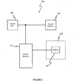
- Figure 1 is a block diagram of a hazard control system according to various aspects of the present invention.
- Figure 2 representatively illustrates an embodiment of the hazard control system.
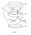
- Figure 3 is an exploded view of a hazard detection system including a housing.
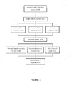
- Figure 4 is a flow diagram of a process for controlling a hazard.
- the present invention may be described in terms of functional block components and various processing steps. Such functional blocks may be realized by any number of hardware or software components configured to perform the specified functions and achieve the various results.
- the present invention may employ various vessels, sensors, detectors, control materials, valves, and the like, which may carry out a variety of functions.
- the present invention may be practiced in conjunction with any number of hazards, and the system described is merely one exemplary application for the invention.
- the present invention may employ any number of conventional techniques for delivering control materials, sensing hazard conditions, controlling valves, and the like.
- a hazard control system 100 for controlling a hazard may comprise a control material source 101 for providing a control material, for example an extinguishant for extinguishing a fire.
- the hazard control system 100 further comprises a hazard detection system 105 for detecting one or more hazards, such a smoke detector, radiation detector, thermal sensor, or gas sensor.
- the hazard control system 100 further comprises a delivery system 107, such as a nozzle 108 coupled to a vessel 102, to deliver the control material to a hazard area 106 in response to the hazard detection system 105.
- the hazard area 106 is an area that may experience a hazard to be controlled by the hazard control system 100.
- the hazard area 106 may comprise the interior of a cabinet, device, vehicle, enclosure, and/or other area.
- the hazard area may comprise an open area that may be affected by the hazard control system 100.
- the control material source 101 may comprise any appropriate source of control material, such as a storage facility containing a control material.
- the source of control material may comprise a vessel 102 configured to store a control material for controlling a hazard.
- the control material may configured to neutralize or combat one or more hazards, such as a fire extinguishant or acid neutralizer.
- the vessel 102 may comprise any suitable system for storing and/or providing the control material, such as a tank, pressurized bottle, reservoir, or other container.
- the vessel 102 may be configured to withstand various operating conditions.
- the vessel 102 may comprise various materials, shapes, dimensions, and coatings according to any appropriate criteria, such as corrosion, cost, deformation, fracture, and/or the like.
- the vessel 102 and the control material may be adapted according the particular hazard and/or environment.
- the vessel 102 may be configured to provide a control material which absorbs or dilutes oxygen levels when transmitted into the hazard area 106.
- the vessel 102 may be configured to provide an extinguishant which absorbs thermal radiation when transmitted into the hazard area 106.
- the delivery system 107 is configured to deliver the control material to the hazard area 106.
- the delivery system 107 may comprise any appropriate system for delivering the control material.
- the delivery system 107 may include a nozzle 108 connected to the vessel 102 and disposed in or adjacent to the hazard area 106 such that control material exiting the nozzle 108 is deposited in the hazard area 106. For example, if a fire is detected in the hazard area 106, a fire extinguishant is transmitted from the vessel 102 through the nozzle 108 to the hazard area 106 to extinguish the fire.
- the nozzle 108 may be connected directly or indirectly to the vessel 102 to deliver the control material.
- the nozzle 108 may be indirectly connected to the vessel 102 via a deployment valve 103, which controls deployment of the control material through the nozzle 108.
- the deployment valve 103 controls whether and, if desired, the amount or type of control material delivered through the nozzle 108.
- the deployment valve 103 may comprise any appropriate mechanism for selectively providing the control material for deployment via the nozzle 108, such as a ball cock, a ball valve, a bibcock, a blast valve, a butterfly valve, a check valve, a double check valve, an electromechanical diaphragm, an electromechanical screw, an electromechanical switch, a freeze valve, a gate valve, a globe valve, a hydraulic valve, a leaf valve, a non-return valve, a pilot valve, a piston valve, a plug valve, a pneumatic valve, a Presta valve, a rotary valve, a Shrader valve, a solenoid valve, and/or the like.
- the deployment valve 103 responds to a signal, for example a pneumatic signal from the hazard detection system 105, and controls delivery of the extinguishant via the nozzle 108 accordingly.
- the hazard detection system 105 generates a hazard signal in response to a detected hazard.
- the hazard detection system 105 may comprise any appropriate system for detecting one or more specific hazards and generating a corresponding signal, such as system for detecting smoke, heat, poison, radiation, and the like.
- the hazard detection system 105 is configured to detect a fire and provide a corresponding signal to the deployment valve 103.
- the hazard signal may comprise any appropriate signal for transmitting relevant information, such as an electrical pulse or signal, acoustic signal, mechanical signal, wireless signal, pneumatic signal, and the like.
- the hazard signal comprises a pneumatic signal generated in response to detection of the hazard condition and provided to the deployment valve 103, which delivers the extinguishant in response to the signal.
- the hazard detection system 105 may generate the hazard signal in any suitable manner, for example in conjunction with conventional hazard, such as a smoke detector, fusible link, infrared detector, radiation detector, or other suitable sensor.
- the hazard detection system 105 detects one or more hazards and generates (or terminates) a corresponding signal.
- the hazard detection system 105 includes a pressure tube 104 configured to generate a signal in response to a change in pressure in the pressure tube 104.
- the hazard detection system further comprises a fire detector 110, configured to release the pressure in the pressure tube 104 upon detecting a hazard condition via a valve 112 connected to the pressure tube 104.
- the hazard detection system 105 generates the pneumatic signal by changing pressure in the pressure tube 104, such as by releasing the pressure in the pressure tube 104.
- the pressure tube 104 may operate with a higher or lower internal pressure than ambient pressure. Equalizing the internal pressure with the ambient pressure generates the pneumatic hazard signal.
- the internal pressure may be achieved and sustained in any suitable manner, for example by pressurizing and sealing the pressure tube 104, connecting the tube to an independent pressure source such as a compressor or pressure bottle, or connecting the pressure tube 104 to the vessel 102 having a pressurized fluid. Any fluid that may be configured to transmit a change in pressure within the pressure tube 104 may be used.
- a substantially incompressible fluid such as a water-based fluid may be sensitive to changes in temperature and/or changes in the internal volume of the pressure tube 104 sufficient to signal coupled devices in response to a change in pressure.
- a substantially inert fluid such as air, nitrogen, or argon may be sensitive to changes in temperature and/or changes in the internal volume of the pressure tube 104 sufficient to signal coupled devices in response to a change in pressure.
- the pressure tube 104 may comprise appropriate materials, including FiretraceTM detection tubing, aluminum, aluminum alloy, cement, ceramic, copper, copper alloy, composites, iron, iron alloy, nickel, nickel alloy, organic materials, polymer, titanium, titanium alloy, rubber, and/or the like.
- the pressure tube 104 may be configured according to any appropriate shapes, dimensions, materials, and coatings according to desired design considerations such as corrosion, cost, deformation, fracture, combinations, and/or the like.
- the pressure changes within the pressure tube 104 may occur based on any cause or condition.
- the pressure in the tube may change in response to a release of pressure in the pressure tube 104, for example due to actuation of the pressure control valve 112.
- pressure changes may be caused by changes in the temperature or volume of the fluid in the pressure tube 104, for example in response to actuation of the pressure control valve 112 or a heat transfer system.
- changes in tube pressure may be induced by multiple mechanisms.
- the pressure tube 104 may be configured to degrade and leak in response to a hazard condition, such as puncture, rupture, deformation, exposure to fire-induced heat, corrosion, radiation, acoustic pressure, changed ambient pressure, particular solids or fluids, mechanical changes such as a change in the tensile properties or configuration of a coupled sacrificial element, and/or the like.
- a hazard condition such as puncture, rupture, deformation, exposure to fire-induced heat, corrosion, radiation, acoustic pressure, changed ambient pressure, particular solids or fluids, mechanical changes such as a change in the tensile properties or configuration of a coupled sacrificial element, and/or the like.
- the hazard detection system 105 may include external systems configured to activate the hazard control system 100.
- Various hazards produce various hazard conditions, which may be detected by the hazard detection system 105.
- fires produce heat and smoke, which may be detected by the fire detector 110, causing the fire detector 110 to activate delivery of the control material.
- the pressure control valve 112 may be configured to affect pressure within the pressure tube 104 in response to signals from another element, such as the fire detector 110.
- the affected pressure may be achieved by configuring the pressure control valve 112 to selectively change the pressure within the pressure tube 104, substantially equalize the pressure within the pressure tube 104 to outside the pressure tube 104, change the temperature of the fluid within the pressure tube 104, and/or the like.
- the fire detector 110 opens the pressure control valve 112 upon detecting a fire, thus allowing the pressure in the pressure tube 104 to escape and generate the pneumatic signal.
- the pressure control valve 112 may comprise any suitable mechanism for controlling the pressure in the pressure tube 104, such as a ball cock, a ball valve, a bibcock, a blast valve, a butterfly valve, a check valve, a double check valve, an electromechanical diaphragm, an electromechanical screw, an electromechanical switch, a freeze valve, a gate valve, a globe valve, a hydraulic valve, a leaf valve, a non-return valve, a pilot valve, a piston valve, a plug valve, a pneumatic valve, a Presta valve, a rotary valve, a Shrader valve, a solenoid valve, and/or the like.
- the pressure control valve 112 comprises an electromechanical system coupled to a power source, for example a landline power source, a battery, and/or the like.
- the pressure control valve 112 comprises a solenoid configured for operation at between about 12 and 24 volts.
- the pressure control valve 112 may be configured to achieve various changes in pressure within the pressure tube 104 by varying the choice of materials, dimensions, power consumption, and/or the like.
- the pressure control valve 112 may be controlled by any suitable systems to change the pressure in the pressure tube 104 in response to a trigger event.
- the hazard detection system 105 may be configured to detect various hazardous conditions that may constitute trigger events.
- the fire detector 110 may detect conditions associated with fires.
- the fire detector 110 may be replaced or supplemented with detectors of other hazards, such as sensors sensitive to incidence with selected substances, radiation levels and/or frequencies, pressures, acoustic pressures, temperatures, tensile properties of a coupled sacrificial element, and/or the like.
- the fire detector 110 suitably comprises a conventional electronic system for fire detection, such as an ionization detector, a mass spectrometer, an optical detector, and/or the like.
- the fire detector 110 receives power from one or more sources, such as a landline power connection, a battery, and/or the like.
- the hazard detection system 105 may control the pressure control valve 112 via any suitable signals, such as electrical signals transmitted via a wire, radio waves, magnetic signals as by an electromagnet, mechanical interaction, infrared signals, acoustic signals, and/or the like.
- the fire detector 110 and pressure control valve 112 are configured such that, upon detection of a fire condition, the fire detector 110 transmits an electrical signal to the pressure control valve 112, which responds by changing the pressure within the pressure tube 104, in particular by opening the pressure control valve 112 to release the pressure.
- the fire detector 110, pressure tube 104, and/or other elements of the hazard detection system 105 may be configured for any variety of fire or other hazard conditions.
- the hazard detection system 105 may monitor for a single hazard condition, such as heat.
- the pressure tube 104 and fire detector 110 serve as substantially independent detection systems of the same hazard condition.
- the hazard may be associated with multiple hazard conditions, such as heat and smoke, in which case different detectors may monitor different conditions.
- the pressure tube 104 and fire detector 110 provide hazard control based on a multiple possible hazard conditions.
- the pressure tube 104 and fire detector 110 may be configured to provide hazard detection in response to partially coextensive hazard conditions.
- the pressure tube 104 and fire detector 110 would provide substantially independent detection systems for some hazard conditions and hazard control based on a variety of input hazard conditions for other hazard conditions. Given the multiplicity of combinations of fire conditions, these examples are illustrative rather than exhaustive.
- the fire detector 110 and the pressure control valve 112 may be configured in any suitable manner to facilitate communication and/or deployment.
- the fire detector 110 may include a wireless transmitter and the pressure control valve 112 may include a wireless receiver to receive wireless control signals from the fire detector 110, which facilitates remote placement of the fire detector 110 relative to the pressure control valve 112.
- the fire detector 110, pressure control valve 112, and/or other elements of the hazard detection system may be connected by hardwire connections, infrared signals, acoustic signals, and the like.
- the fire detector 110 and pressure control valve 112 are at least partially disposed within a housing 400 to form a single unit.
- the housing 400 may be configured to facilitate installation and power supply to the fire detector 110 and the pressure control valve 112.
- the housing 400 includes an area for housing the fire detector 110, such as a conventional housing having slots or other exposure permitting the fire detector 110 to sense the ambient atmosphere.
- the housing 400 further includes an area for the pressure control valve 112, which is connected to the fire detector 110 to receive signals from the fire detector 110.
- the housing 400 may further be configured to substantially accommodate a portion of the pressure tube 104 to facilitate control of the pressure in the pressure tube 104 by the pressure control valve 112.
- the housing 400 may include one or more apertures through which the end of the pressure tube 104 may be connected to the pressure control valve 112.
- the housing 400 may comprise various materials including aluminum, aluminum alloy, cement, ceramic, copper, copper alloy, composites, iron, iron alloy, nickel, nickel alloy, organic materials, polymer, titanium, titanium alloy, and/or the like.
- the housing 400 may comprise various shapes, dimensions, and coatings according to various design considerations such as corrosion, cost, deformation, fracture, and/or the like.
- the housing 400 may be configured to include emissive properties with respect to ambient conditions and these properties may be achieved by including vents, holes, slats, permeable membranes, semi-permeable membranes, selectively permeable membranes, and/or the like within at least a portion of the housing 400. Further, the housing 400 may be disassembled into multiple sections 400A-400C to facilitate installation and/or maintenance.
- the housing 400 may be configured to provide power to the elements of the system, such as the fire detector 110 and the pressure control valve 112.
- the power source may comprise any appropriates forms and source of power for the various elements.
- the power source may include a main power source and a backup power source.
- the main power source comprises a connection for receiving power from a conventional distribution outlet.
- the backup power source is configured to provide power in the event of a failure of the main power source, and may comprise any suitable source of power, such as one or more capacitors, batteries, uninterruptible power supplies, generators, solar cells, and/or the like.
- the backup power source includes two batteries 402, 404 disposed within the housing 400.
- the first battery 402 provides backup power to the fire detector 110 and the second battery 404 provides backup power to the pressure control valve 112.
- the pressure control valve 112 requires a higher power, more expensive, and/or less reliable battery than the fire detector 110.
- the valve battery 404 may fail without disabling the backup power for the fire detector 110 supplied by the fire detector battery 402.
- the hazard control system 100 may be further configured to operate autonomously or in conjunction with external systems, for example a fire system control unit 109 for a building or the like.
- the operation with the external systems may be configured in any suitable manner, for example to initiate an alarm, control the operation of the hazard control system 100, automatically notify emergency services, and/or the like.
- the hazard control system 100 may include a communication interface connected to a remote control unit to signal the control unit 109 in response to a detected fire condition.
- the hazard control system 100 may be configured to respond to signals from the remote control unit 109, for example to provide status indicators for the hazard control system 100 and/or remotely activate the hazard control system 100.
- the hazard control system 100 may further comprise additional elements for controlling and activating the hazard control system.
- the hazard control system may include a manual system for manually activating the hazard control system.
- the hazard control system 100 includes a manual valve 202 configured for manually activating the hazard control system 100.
- the manual valve 202 may be coupled to the pressure tube 104 such that the manual valve 202 may release the internal pressure of the pressure tube 104.
- the manual valve 202 may be operated in any suitable manner, such as manual manipulation of the valve or in conjunction with an actuator, such as motor or the like.
- the manual valve 202 may be located in any suitable location, such as substantially outside of the hazard area 106 or within the hazard area 106.
- the manual valve 202 may be coupled to the vessel 102, pressure tube 104, pressure control valve 112, and/or the like.
- the manual valve 202 may be configured for operation with the vessel 102 such that actuation of the manual valve 202 directs extinguishant to the nozzle 108.
- the manual valve 202 may be configured for operation with the pressure tube 104 such that actuation of the manual valve 202 causes a change in pressure within the pressure tube 104 sufficient to direct extinguishant to the nozzle 108.
- the manual valve 202 may further be configured for operation with the pressure control valve 112 such that actuation of the manual valve 202 causes actuation of the pressure control valve 112, causing a change in pressure within the pressure tube 104 sufficient to direct extinguishant to the nozzle 108.
- the hazard control system 100 may further comprise systems for providing additional responses in the event of a hazard being detected such that the hazard control system 100 may initiate further responses in addition to delivering the extinguishant in the event that a hazard is detected.
- the hazard control system 100 may be configured to prompt any appropriate response, such as alerting emergency personnel, sealing off an area from unauthorized personnel, terminating or initiating ventilation of an area, deactivating hazardous machinery, and/or the like.
- the hazard control system 100 may comprise a supplementary pressure switch 302.
- the supplementary pressure switch 302 may facilitate transmitting information relating to changes in pressure within the pressure tube 104 to external systems, such as be generating an electrical signal, mechanical signal, and/or other suitable signal in response to a pressure change within the coupled pressure tube 104.
- the supplementary pressure switch 302 may be coupled to machinery in the vicinity of the hazard area 106 to cut power or fuel supply to the machinery in the event that the supplementary pressure switch 302 produces a signal indicating a hazard condition as detected by the hazard control system 100.
- the hazard control system 100 may be configured with multiple vessels 102, pressure tubes 104, nozzles 108, pressure control valves 112, hazard detectors 110, manual valves 202, and/or supplementary pressure switches 302.
- the hazard control system 100 may be configured to include multiple vessels 102 coupled to a single nozzle 108 and hazard detector 110, such as if controlling the hazard area 106 includes drawing multiple types of extinguishant which cannot be stored together, or if the extinguishing anticipated hazards may require different extinguishants to be applied at different times.
- the hazard control system 100 may be configured to include more than one pressure tube 104 coupled to a single nozzle 108 and hazard detector 110, for example to provide multiple paths for delivering the extinguishant, or to draw different extinguishants in response to different fire conditions. Given the multiplicity of combinations of elements, these examples are illustrative rather than exhaustive.
- the hazard control system 100 is initially configured such that the hazard detection system 105 may sense relevant indicators of hazard conditions (410).
- the pressure tube 104 may be exposed to the interior of a room or other enclosure so that in the event of a fire, the pressure tube 104 is exposed to heat from the fire.
- relevant sensors such as the fire detector 110, may be positioned to sense relevant phenomena should a hazard occur.
- the delivery system 107 is also suitably configured to deliver a control material to areas where a hazard may occur (412).
- the hazard detection system may detect the hazard and activate the hazard control system 100.
- the heat of a fire may degrade the pressure tube 104 (414), causing the interior pressure of the pressure tube 104 to be released, thus generating a pneumatic signal (420).
- a sensor such as a smoke detector, may sense smoke or another relevant hazard indicator (416) and activate the hazard control system 100.
- the sensor may open the pressure control valve 112, likewise releasing the pressure in the pressure tube 104 and generating the pneumatic signal.
- the signal may be generated by other systems, such as an external system or the manual valve 202 (418).
- the signal is received by the deployment valve, which opens (422) in response to the signal to deliver the control material.
- the control material is dispensed through the delivery system into the area of the hazard (424), thus tending to control the hazard.
- the signal may also be received and/or transmitted to other systems, such as the control unit (426) and/or the supplementary pressure switch 302 (428).
- the terms "comprises”, “comprising”, or any variation thereof, are intended to reference a non-exclusive inclusion, such that a process, method, article, composition or apparatus that comprises a list of elements does not include only those elements recited, but may also include other elements not expressly listed or inherent to such process, method, article, composition or apparatus.
- Other combinations and/or modifications of the above-described structures, arrangements, applications, proportions, elements, materials or components used in the practice of the present invention, in addition to those not specifically recited, may be varied or otherwise particularly adapted to specific environments, manufacturing specifications, design parameters or other operating requirements without departing from the general principles of the same.
Landscapes
- Health & Medical Sciences (AREA)
- Public Health (AREA)
- Business, Economics & Management (AREA)
- Emergency Management (AREA)
- Fire-Extinguishing By Fire Departments, And Fire-Extinguishing Equipment And Control Thereof (AREA)
- Fire Alarms (AREA)
- Control Of Eletrric Generators (AREA)
- Lighting Device Outwards From Vehicle And Optical Signal (AREA)
Applications Claiming Priority (2)
| Application Number | Priority Date | Filing Date | Title |
|---|---|---|---|
| US94958607P | 2007-07-13 | 2007-07-13 | |
| EP08772530A EP2167198B1 (en) | 2007-07-13 | 2008-07-11 | Methods and apparatus for hazard control |
Related Parent Applications (2)
| Application Number | Title | Priority Date | Filing Date |
|---|---|---|---|
| EP08772530.5 Division | 2008-07-11 | ||
| EP08772530A Division EP2167198B1 (en) | 2007-07-13 | 2008-07-11 | Methods and apparatus for hazard control |
Publications (2)
| Publication Number | Publication Date |
|---|---|
| EP2428253A1 EP2428253A1 (en) | 2012-03-14 |
| EP2428253B1 true EP2428253B1 (en) | 2015-10-14 |
Family
ID=40260010
Family Applications (2)
| Application Number | Title | Priority Date | Filing Date |
|---|---|---|---|
| EP11192338.9A Not-in-force EP2428253B1 (en) | 2007-07-13 | 2008-07-11 | Methods and apparatus for hazard control |
| EP08772530A Not-in-force EP2167198B1 (en) | 2007-07-13 | 2008-07-11 | Methods and apparatus for hazard control |
Family Applications After (1)
| Application Number | Title | Priority Date | Filing Date |
|---|---|---|---|
| EP08772530A Not-in-force EP2167198B1 (en) | 2007-07-13 | 2008-07-11 | Methods and apparatus for hazard control |
Country Status (9)
| Country | Link |
|---|---|
| US (2) | US7823650B2 (cg-RX-API-DMAC7.html) |
| EP (2) | EP2428253B1 (cg-RX-API-DMAC7.html) |
| JP (2) | JP5356379B2 (cg-RX-API-DMAC7.html) |
| KR (1) | KR101426115B1 (cg-RX-API-DMAC7.html) |
| AT (1) | ATE540728T1 (cg-RX-API-DMAC7.html) |
| AU (1) | AU2008276205B2 (cg-RX-API-DMAC7.html) |
| CA (1) | CA2693414C (cg-RX-API-DMAC7.html) |
| ES (2) | ES2557403T3 (cg-RX-API-DMAC7.html) |
| WO (1) | WO2009012179A1 (cg-RX-API-DMAC7.html) |
Families Citing this family (27)
| Publication number | Priority date | Publication date | Assignee | Title |
|---|---|---|---|---|
| US8459369B2 (en) | 2007-07-13 | 2013-06-11 | Firetrace Usa, Llc | Methods and apparatus for hazard control and signaling |
| US8505642B2 (en) * | 2009-11-05 | 2013-08-13 | Firetrace Usa, Llc | Methods and apparatus for dual stage hazard control system |
| DE102010028857B4 (de) * | 2010-05-11 | 2012-03-22 | Fiwarec Valves & Regulators Gmbh & Co. Kg | Automatische Brandlöschanlage |
| US8646540B2 (en) * | 2010-07-20 | 2014-02-11 | Firetrace Usa, Llc | Methods and apparatus for passive non-electrical dual stage fire suppression |
| DE102010035525B4 (de) * | 2010-08-25 | 2012-06-14 | Minimax Gmbh & Co. Kg | Vorrichtung zum Löschen von Bränden |
| US8863856B2 (en) * | 2011-02-09 | 2014-10-21 | Firetrace Usa, Llc | Methods and apparatus for multi-stage fire suppression |
| DK2714282T3 (da) | 2011-05-27 | 2023-11-20 | Victaulic Co Of America | X-Ophængt ventil og fleksibel forbindelse til brandsprinklere |
| US9358411B2 (en) | 2011-05-27 | 2016-06-07 | Victaulic Company | Flexible dry sprinkler |
| EP2722077B1 (en) * | 2012-10-17 | 2019-08-14 | Fogmaker International AB | Fire detection system |
| US9415250B2 (en) | 2012-12-20 | 2016-08-16 | Victaulic Company | Dry sprinkler |
| US10449402B2 (en) | 2012-12-20 | 2019-10-22 | Victaulic Company | Dry sprinkler |
| US9345918B2 (en) | 2012-12-20 | 2016-05-24 | Victaulic Company | Dry sprinkler |
| EP2959946B1 (en) * | 2014-06-27 | 2019-04-24 | Fogmaker International AB | Fire extinguishing system |
| US9393452B2 (en) * | 2014-07-29 | 2016-07-19 | Dan Swift | Anechoic chamber fire suppression system |
| US9884212B2 (en) * | 2014-07-29 | 2018-02-06 | Dan Swift | Anechoic chamber fire suppression system |
| CN105582634A (zh) * | 2014-10-20 | 2016-05-18 | 全龙浩 | 可重复启闭工作的感温管系统 |
| US10646736B2 (en) | 2015-07-28 | 2020-05-12 | Victaulic Company | Preaction sprinkler valve assemblies, related dry sprinkler devices adapted for long travel, and fire protection sprinkler systems |
| KR102687803B1 (ko) | 2015-07-28 | 2024-07-24 | 글로브 파이어 스프링클러 코포레이션 | 사전작용 스프링클러 밸브 조립체 |
| US20170120089A1 (en) * | 2015-10-30 | 2017-05-04 | Firetrace Usa, Llc | Methods and apparatus for fire suppression system for transportable container |
| EP3454951B1 (en) * | 2016-05-10 | 2022-10-19 | Fike Corporation | Intelligent temperature and pressure gauge assembly |
| US10850144B2 (en) | 2017-06-14 | 2020-12-01 | Victaulic Company | Preaction sprinkler valve assemblies, related dry sprinkler devices, and compressive activation mechanism |
| US11045675B2 (en) | 2018-02-02 | 2021-06-29 | Victaulic Company | Belleville seal for valve seat having a tear drop laminar flow feature |
| CN110538405A (zh) * | 2019-09-29 | 2019-12-06 | 安徽芯核防务装备技术股份有限公司 | 一种新型火灾探测与灭火装置 |
| CN113941105B (zh) * | 2020-07-16 | 2023-12-19 | 哲弗智能系统(上海)有限公司 | 智能热触发灭火装置、方法、电池包、储能系统及车辆 |
| CN116490245A (zh) | 2020-10-29 | 2023-07-25 | 科慕埃弗西有限公司 | 锂离子电池的热保护 |
| TW202239047A (zh) | 2021-03-19 | 2022-10-01 | 美商科慕Fc有限責任公司 | 鋰離子電池組的熱防護 |
| TW202239046A (zh) | 2021-03-19 | 2022-10-01 | 美商科慕Fc有限責任公司 | 鋰離子電池組的熱防護 |
Family Cites Families (19)
| Publication number | Priority date | Publication date | Assignee | Title |
|---|---|---|---|---|
| US4356868A (en) * | 1980-07-30 | 1982-11-02 | Ransburg Corporation | Fire-extinguishant system |
| JPS5937562B2 (ja) * | 1983-04-27 | 1984-09-11 | 靖通 伯耆 | 変圧器の消火装置 |
| JPS6037349U (ja) * | 1983-08-22 | 1985-03-14 | ホーチキ株式会社 | 乾式泡消火設備 |
| DE3506152A1 (de) * | 1985-02-22 | 1986-08-28 | Festo KG, 7300 Esslingen | Ueberwachungseinrichtung in form einer pneumatischen schaltungsanordnung |
| US4650003A (en) * | 1985-04-10 | 1987-03-17 | Systecon Inc. | Light path heat detector |
| US5315292A (en) * | 1993-01-11 | 1994-05-24 | Prior Mitchell K | Ceiling mountable smoke detector and fire extinguisher combination |
| JP3697618B2 (ja) * | 1995-02-17 | 2005-09-21 | 能美防災株式会社 | エンジンルーム消火装置 |
| DE19530355C1 (de) * | 1995-08-18 | 1997-04-03 | Juergen Haro | Stationäre Löscheinrichtung zum Versprühen eines Löschmittels mit wenigstens einer in einen Raum oder auf einen Gegenstand gerichteten Sprühdüse |
| US5954138A (en) * | 1996-03-20 | 1999-09-21 | Ceodeux-Fire Extinguisher Valves Technology S.A. | Fire extinguisher valve and fire-extinguishing equipment |
| JP3238879B2 (ja) * | 1997-03-18 | 2001-12-17 | ホーチキ株式会社 | 火災検出消火システム |
| US6079502A (en) * | 1998-11-06 | 2000-06-27 | Lucent Technologies Inc. | Process station fire suppression system |
| DE19945856B4 (de) * | 1999-09-24 | 2005-12-29 | Robert Bosch Gmbh | Sprinklervorrichtung mit einem Ventil für Löschflüssigkeit |
| US6708771B2 (en) * | 2000-03-27 | 2004-03-23 | Victaulic Company Of America | Low pressure electro-pneumatic and gate actuator |
| JP4210821B2 (ja) * | 2001-03-30 | 2009-01-21 | 能美防災株式会社 | スプリンクラ消火設備 |
| US6648077B2 (en) * | 2001-07-12 | 2003-11-18 | Bryan K. Hoffman | Fire extinguishing system |
| JP2003290383A (ja) * | 2002-03-29 | 2003-10-14 | Nohmi Bosai Ltd | パッケージ型自動消火設備 |
| US6952169B1 (en) * | 2002-10-22 | 2005-10-04 | Adrian Simtion | Cordless/wireless automatic detection and suppression system |
| JP4140832B2 (ja) * | 2003-06-13 | 2008-08-27 | 千住スプリンクラー株式会社 | スプリンクラーヘッド |
| KR20040027534A (ko) * | 2004-02-10 | 2004-04-01 | 정재묵 | 선형 화재감지튜브 및 무전원 자동 소화시스템 |
-
2008
- 2008-07-11 ES ES11192338.9T patent/ES2557403T3/es active Active
- 2008-07-11 JP JP2010516286A patent/JP5356379B2/ja not_active Expired - Fee Related
- 2008-07-11 KR KR1020107003030A patent/KR101426115B1/ko not_active Expired - Fee Related
- 2008-07-11 EP EP11192338.9A patent/EP2428253B1/en not_active Not-in-force
- 2008-07-11 AU AU2008276205A patent/AU2008276205B2/en not_active Ceased
- 2008-07-11 US US12/172,148 patent/US7823650B2/en active Active
- 2008-07-11 ES ES08772530T patent/ES2379134T3/es active Active
- 2008-07-11 EP EP08772530A patent/EP2167198B1/en not_active Not-in-force
- 2008-07-11 CA CA2693414A patent/CA2693414C/en not_active Expired - Fee Related
- 2008-07-11 WO PCT/US2008/069871 patent/WO2009012179A1/en not_active Ceased
- 2008-07-11 AT AT08772530T patent/ATE540728T1/de active
-
2010
- 2010-09-24 US US12/890,321 patent/US8087468B2/en active Active
-
2011
- 2011-08-16 JP JP2011177952A patent/JP5373012B2/ja not_active Expired - Fee Related
Also Published As
| Publication number | Publication date |
|---|---|
| ES2379134T3 (es) | 2012-04-23 |
| US8087468B2 (en) | 2012-01-03 |
| KR20100032930A (ko) | 2010-03-26 |
| AU2008276205A1 (en) | 2009-01-22 |
| ES2557403T3 (es) | 2016-01-25 |
| JP5373012B2 (ja) | 2013-12-18 |
| JP2012038322A (ja) | 2012-02-23 |
| KR101426115B1 (ko) | 2014-08-05 |
| JP5356379B2 (ja) | 2013-12-04 |
| WO2009012179A1 (en) | 2009-01-22 |
| EP2428253A1 (en) | 2012-03-14 |
| CA2693414C (en) | 2015-12-29 |
| EP2167198A1 (en) | 2010-03-31 |
| US20090178813A1 (en) | 2009-07-16 |
| EP2167198B1 (en) | 2012-01-11 |
| JP2010533907A (ja) | 2010-10-28 |
| EP2167198A4 (en) | 2010-08-11 |
| CA2693414A1 (en) | 2009-01-22 |
| AU2008276205B2 (en) | 2012-04-12 |
| ATE540728T1 (de) | 2012-01-15 |
| US7823650B2 (en) | 2010-11-02 |
| US20110011600A1 (en) | 2011-01-20 |
Similar Documents
| Publication | Publication Date | Title |
|---|---|---|
| EP2428253B1 (en) | Methods and apparatus for hazard control | |
| CA2812266C (en) | Methods and apparatus for hazard control and signaling | |
| EP2308567B1 (en) | Fire suppression system | |
| US9656107B2 (en) | Trigger unit for extinguishing devices | |
| CA2819698C (en) | Methods and apparatus for multi-stage fire suppression | |
| WO2012012079A1 (en) | Methods and apparatus for passive non-electrical dual stage fire suppresion | |
| AU2011204975B2 (en) | Methods and apparatus for hazard control | |
| AU2011280137B2 (en) | Methods and apparatus for passive non-electrical dual stage fire suppresion | |
| GB2562527A (en) | A venting valve assembly for a fluid storage vessel |
Legal Events
| Date | Code | Title | Description |
|---|---|---|---|
| 17P | Request for examination filed |
Effective date: 20111207 |
|
| AC | Divisional application: reference to earlier application |
Ref document number: 2167198 Country of ref document: EP Kind code of ref document: P |
|
| AK | Designated contracting states |
Kind code of ref document: A1 Designated state(s): AT BE BG CH CY CZ DE DK EE ES FI FR GB GR HR HU IE IS IT LI LT LU LV MC MT NL NO PL PT RO SE SI SK TR |
|
| PUAI | Public reference made under article 153(3) epc to a published international application that has entered the european phase |
Free format text: ORIGINAL CODE: 0009012 |
|
| 17Q | First examination report despatched |
Effective date: 20120703 |
|
| GRAP | Despatch of communication of intention to grant a patent |
Free format text: ORIGINAL CODE: EPIDOSNIGR1 |
|
| INTG | Intention to grant announced |
Effective date: 20150429 |
|
| GRAS | Grant fee paid |
Free format text: ORIGINAL CODE: EPIDOSNIGR3 |
|
| GRAA | (expected) grant |
Free format text: ORIGINAL CODE: 0009210 |
|
| AC | Divisional application: reference to earlier application |
Ref document number: 2167198 Country of ref document: EP Kind code of ref document: P |
|
| AK | Designated contracting states |
Kind code of ref document: B1 Designated state(s): AT BE BG CH CY CZ DE DK EE ES FI FR GB GR HR HU IE IS IT LI LT LU LV MC MT NL NO PL PT RO SE SI SK TR |
|
| REG | Reference to a national code |
Ref country code: GB Ref legal event code: FG4D |
|
| REG | Reference to a national code |
Ref country code: AT Ref legal event code: REF Ref document number: 754664 Country of ref document: AT Kind code of ref document: T Effective date: 20151015 Ref country code: CH Ref legal event code: EP |
|
| REG | Reference to a national code |
Ref country code: IE Ref legal event code: FG4D |
|
| REG | Reference to a national code |
Ref country code: DE Ref legal event code: R096 Ref document number: 602008040731 Country of ref document: DE |
|
| REG | Reference to a national code |
Ref country code: ES Ref legal event code: FG2A Ref document number: 2557403 Country of ref document: ES Kind code of ref document: T3 Effective date: 20160125 |
|
| REG | Reference to a national code |
Ref country code: LT Ref legal event code: MG4D |
|
| REG | Reference to a national code |
Ref country code: NL Ref legal event code: FP |
|
| REG | Reference to a national code |
Ref country code: AT Ref legal event code: MK05 Ref document number: 754664 Country of ref document: AT Kind code of ref document: T Effective date: 20151014 |
|
| PG25 | Lapsed in a contracting state [announced via postgrant information from national office to epo] |
Ref country code: HR Free format text: LAPSE BECAUSE OF FAILURE TO SUBMIT A TRANSLATION OF THE DESCRIPTION OR TO PAY THE FEE WITHIN THE PRESCRIBED TIME-LIMIT Effective date: 20151014 Ref country code: IS Free format text: LAPSE BECAUSE OF FAILURE TO SUBMIT A TRANSLATION OF THE DESCRIPTION OR TO PAY THE FEE WITHIN THE PRESCRIBED TIME-LIMIT Effective date: 20160214 Ref country code: NO Free format text: LAPSE BECAUSE OF FAILURE TO SUBMIT A TRANSLATION OF THE DESCRIPTION OR TO PAY THE FEE WITHIN THE PRESCRIBED TIME-LIMIT Effective date: 20160114 Ref country code: LT Free format text: LAPSE BECAUSE OF FAILURE TO SUBMIT A TRANSLATION OF THE DESCRIPTION OR TO PAY THE FEE WITHIN THE PRESCRIBED TIME-LIMIT Effective date: 20151014 |
|
| PG25 | Lapsed in a contracting state [announced via postgrant information from national office to epo] |
Ref country code: AT Free format text: LAPSE BECAUSE OF FAILURE TO SUBMIT A TRANSLATION OF THE DESCRIPTION OR TO PAY THE FEE WITHIN THE PRESCRIBED TIME-LIMIT Effective date: 20151014 Ref country code: SE Free format text: LAPSE BECAUSE OF FAILURE TO SUBMIT A TRANSLATION OF THE DESCRIPTION OR TO PAY THE FEE WITHIN THE PRESCRIBED TIME-LIMIT Effective date: 20151014 Ref country code: PL Free format text: LAPSE BECAUSE OF FAILURE TO SUBMIT A TRANSLATION OF THE DESCRIPTION OR TO PAY THE FEE WITHIN THE PRESCRIBED TIME-LIMIT Effective date: 20151014 Ref country code: PT Free format text: LAPSE BECAUSE OF FAILURE TO SUBMIT A TRANSLATION OF THE DESCRIPTION OR TO PAY THE FEE WITHIN THE PRESCRIBED TIME-LIMIT Effective date: 20160215 Ref country code: FI Free format text: LAPSE BECAUSE OF FAILURE TO SUBMIT A TRANSLATION OF THE DESCRIPTION OR TO PAY THE FEE WITHIN THE PRESCRIBED TIME-LIMIT Effective date: 20151014 Ref country code: LV Free format text: LAPSE BECAUSE OF FAILURE TO SUBMIT A TRANSLATION OF THE DESCRIPTION OR TO PAY THE FEE WITHIN THE PRESCRIBED TIME-LIMIT Effective date: 20151014 Ref country code: GR Free format text: LAPSE BECAUSE OF FAILURE TO SUBMIT A TRANSLATION OF THE DESCRIPTION OR TO PAY THE FEE WITHIN THE PRESCRIBED TIME-LIMIT Effective date: 20160115 |
|
| REG | Reference to a national code |
Ref country code: FR Ref legal event code: PLFP Year of fee payment: 9 |
|
| REG | Reference to a national code |
Ref country code: DE Ref legal event code: R097 Ref document number: 602008040731 Country of ref document: DE |
|
| PG25 | Lapsed in a contracting state [announced via postgrant information from national office to epo] |
Ref country code: CZ Free format text: LAPSE BECAUSE OF FAILURE TO SUBMIT A TRANSLATION OF THE DESCRIPTION OR TO PAY THE FEE WITHIN THE PRESCRIBED TIME-LIMIT Effective date: 20151014 |
|
| PLBE | No opposition filed within time limit |
Free format text: ORIGINAL CODE: 0009261 |
|
| STAA | Information on the status of an ep patent application or granted ep patent |
Free format text: STATUS: NO OPPOSITION FILED WITHIN TIME LIMIT |
|
| PG25 | Lapsed in a contracting state [announced via postgrant information from national office to epo] |
Ref country code: EE Free format text: LAPSE BECAUSE OF FAILURE TO SUBMIT A TRANSLATION OF THE DESCRIPTION OR TO PAY THE FEE WITHIN THE PRESCRIBED TIME-LIMIT Effective date: 20151014 Ref country code: DK Free format text: LAPSE BECAUSE OF FAILURE TO SUBMIT A TRANSLATION OF THE DESCRIPTION OR TO PAY THE FEE WITHIN THE PRESCRIBED TIME-LIMIT Effective date: 20151014 Ref country code: RO Free format text: LAPSE BECAUSE OF FAILURE TO SUBMIT A TRANSLATION OF THE DESCRIPTION OR TO PAY THE FEE WITHIN THE PRESCRIBED TIME-LIMIT Effective date: 20151014 Ref country code: SK Free format text: LAPSE BECAUSE OF FAILURE TO SUBMIT A TRANSLATION OF THE DESCRIPTION OR TO PAY THE FEE WITHIN THE PRESCRIBED TIME-LIMIT Effective date: 20151014 |
|
| 26N | No opposition filed |
Effective date: 20160715 |
|
| PG25 | Lapsed in a contracting state [announced via postgrant information from national office to epo] |
Ref country code: SI Free format text: LAPSE BECAUSE OF FAILURE TO SUBMIT A TRANSLATION OF THE DESCRIPTION OR TO PAY THE FEE WITHIN THE PRESCRIBED TIME-LIMIT Effective date: 20151014 |
|
| REG | Reference to a national code |
Ref country code: CH Ref legal event code: PL |
|
| PG25 | Lapsed in a contracting state [announced via postgrant information from national office to epo] |
Ref country code: MC Free format text: LAPSE BECAUSE OF FAILURE TO SUBMIT A TRANSLATION OF THE DESCRIPTION OR TO PAY THE FEE WITHIN THE PRESCRIBED TIME-LIMIT Effective date: 20151014 |
|
| PG25 | Lapsed in a contracting state [announced via postgrant information from national office to epo] |
Ref country code: LI Free format text: LAPSE BECAUSE OF NON-PAYMENT OF DUE FEES Effective date: 20160731 Ref country code: CH Free format text: LAPSE BECAUSE OF NON-PAYMENT OF DUE FEES Effective date: 20160731 |
|
| REG | Reference to a national code |
Ref country code: IE Ref legal event code: MM4A |
|
| REG | Reference to a national code |
Ref country code: FR Ref legal event code: PLFP Year of fee payment: 10 |
|
| PG25 | Lapsed in a contracting state [announced via postgrant information from national office to epo] |
Ref country code: IE Free format text: LAPSE BECAUSE OF NON-PAYMENT OF DUE FEES Effective date: 20160711 |
|
| PGFP | Annual fee paid to national office [announced via postgrant information from national office to epo] |
Ref country code: LU Payment date: 20170713 Year of fee payment: 10 Ref country code: NL Payment date: 20170711 Year of fee payment: 10 |
|
| PGFP | Annual fee paid to national office [announced via postgrant information from national office to epo] |
Ref country code: GB Payment date: 20170822 Year of fee payment: 10 Ref country code: IT Payment date: 20170712 Year of fee payment: 10 Ref country code: DE Payment date: 20170817 Year of fee payment: 10 Ref country code: ES Payment date: 20170919 Year of fee payment: 10 Ref country code: FR Payment date: 20170718 Year of fee payment: 10 |
|
| PGFP | Annual fee paid to national office [announced via postgrant information from national office to epo] |
Ref country code: BE Payment date: 20170731 Year of fee payment: 10 |
|
| PG25 | Lapsed in a contracting state [announced via postgrant information from national office to epo] |
Ref country code: CY Free format text: LAPSE BECAUSE OF FAILURE TO SUBMIT A TRANSLATION OF THE DESCRIPTION OR TO PAY THE FEE WITHIN THE PRESCRIBED TIME-LIMIT Effective date: 20151014 Ref country code: HU Free format text: LAPSE BECAUSE OF FAILURE TO SUBMIT A TRANSLATION OF THE DESCRIPTION OR TO PAY THE FEE WITHIN THE PRESCRIBED TIME-LIMIT; INVALID AB INITIO Effective date: 20080711 |
|
| PG25 | Lapsed in a contracting state [announced via postgrant information from national office to epo] |
Ref country code: TR Free format text: LAPSE BECAUSE OF FAILURE TO SUBMIT A TRANSLATION OF THE DESCRIPTION OR TO PAY THE FEE WITHIN THE PRESCRIBED TIME-LIMIT Effective date: 20151014 Ref country code: MT Free format text: LAPSE BECAUSE OF NON-PAYMENT OF DUE FEES Effective date: 20160731 |
|
| PG25 | Lapsed in a contracting state [announced via postgrant information from national office to epo] |
Ref country code: BG Free format text: LAPSE BECAUSE OF FAILURE TO SUBMIT A TRANSLATION OF THE DESCRIPTION OR TO PAY THE FEE WITHIN THE PRESCRIBED TIME-LIMIT Effective date: 20151014 |
|
| REG | Reference to a national code |
Ref country code: DE Ref legal event code: R119 Ref document number: 602008040731 Country of ref document: DE |
|
| REG | Reference to a national code |
Ref country code: NL Ref legal event code: MM Effective date: 20180801 |
|
| GBPC | Gb: european patent ceased through non-payment of renewal fee |
Effective date: 20180711 |
|
| PG25 | Lapsed in a contracting state [announced via postgrant information from national office to epo] |
Ref country code: LU Free format text: LAPSE BECAUSE OF NON-PAYMENT OF DUE FEES Effective date: 20180711 |
|
| REG | Reference to a national code |
Ref country code: BE Ref legal event code: FP Effective date: 20151222 Ref country code: BE Ref legal event code: MM Effective date: 20180731 |
|
| PG25 | Lapsed in a contracting state [announced via postgrant information from national office to epo] |
Ref country code: GB Free format text: LAPSE BECAUSE OF NON-PAYMENT OF DUE FEES Effective date: 20180711 Ref country code: DE Free format text: LAPSE BECAUSE OF NON-PAYMENT OF DUE FEES Effective date: 20190201 Ref country code: FR Free format text: LAPSE BECAUSE OF NON-PAYMENT OF DUE FEES Effective date: 20180731 |
|
| PG25 | Lapsed in a contracting state [announced via postgrant information from national office to epo] |
Ref country code: NL Free format text: LAPSE BECAUSE OF NON-PAYMENT OF DUE FEES Effective date: 20180801 Ref country code: BE Free format text: LAPSE BECAUSE OF NON-PAYMENT OF DUE FEES Effective date: 20180731 |
|
| PG25 | Lapsed in a contracting state [announced via postgrant information from national office to epo] |
Ref country code: IT Free format text: LAPSE BECAUSE OF NON-PAYMENT OF DUE FEES Effective date: 20180711 |
|
| REG | Reference to a national code |
Ref country code: ES Ref legal event code: FD2A Effective date: 20190917 |
|
| PG25 | Lapsed in a contracting state [announced via postgrant information from national office to epo] |
Ref country code: ES Free format text: LAPSE BECAUSE OF NON-PAYMENT OF DUE FEES Effective date: 20180712 |