EP2427351B1 - Side airbag unit for vehicle - Google Patents
Side airbag unit for vehicle Download PDFInfo
- Publication number
- EP2427351B1 EP2427351B1 EP10772259.7A EP10772259A EP2427351B1 EP 2427351 B1 EP2427351 B1 EP 2427351B1 EP 10772259 A EP10772259 A EP 10772259A EP 2427351 B1 EP2427351 B1 EP 2427351B1
- Authority
- EP
- European Patent Office
- Prior art keywords
- airbag
- tether
- vent hole
- blocking member
- tethers
- Prior art date
- Legal status (The legal status is an assumption and is not a legal conclusion. Google has not performed a legal analysis and makes no representation as to the accuracy of the status listed.)
- Active
Links
Images

Classifications
-
- B—PERFORMING OPERATIONS; TRANSPORTING
- B60—VEHICLES IN GENERAL
- B60R—VEHICLES, VEHICLE FITTINGS, OR VEHICLE PARTS, NOT OTHERWISE PROVIDED FOR
- B60R21/00—Arrangements or fittings on vehicles for protecting or preventing injuries to occupants or pedestrians in case of accidents or other traffic risks
- B60R21/02—Occupant safety arrangements or fittings, e.g. crash pads
- B60R21/16—Inflatable occupant restraints or confinements designed to inflate upon impact or impending impact, e.g. air bags
- B60R21/20—Arrangements for storing inflatable members in their non-use or deflated condition; Arrangement or mounting of air bag modules or components
- B60R21/21—Arrangements for storing inflatable members in their non-use or deflated condition; Arrangement or mounting of air bag modules or components in vehicle side panels, e.g. doors
-
- B—PERFORMING OPERATIONS; TRANSPORTING
- B60—VEHICLES IN GENERAL
- B60R—VEHICLES, VEHICLE FITTINGS, OR VEHICLE PARTS, NOT OTHERWISE PROVIDED FOR
- B60R21/00—Arrangements or fittings on vehicles for protecting or preventing injuries to occupants or pedestrians in case of accidents or other traffic risks
- B60R21/02—Occupant safety arrangements or fittings, e.g. crash pads
- B60R21/16—Inflatable occupant restraints or confinements designed to inflate upon impact or impending impact, e.g. air bags
- B60R21/23—Inflatable members
- B60R21/239—Inflatable members characterised by their venting means
-
- B—PERFORMING OPERATIONS; TRANSPORTING
- B60—VEHICLES IN GENERAL
- B60R—VEHICLES, VEHICLE FITTINGS, OR VEHICLE PARTS, NOT OTHERWISE PROVIDED FOR
- B60R21/00—Arrangements or fittings on vehicles for protecting or preventing injuries to occupants or pedestrians in case of accidents or other traffic risks
- B60R21/02—Occupant safety arrangements or fittings, e.g. crash pads
- B60R21/16—Inflatable occupant restraints or confinements designed to inflate upon impact or impending impact, e.g. air bags
-
- B—PERFORMING OPERATIONS; TRANSPORTING
- B60—VEHICLES IN GENERAL
- B60R—VEHICLES, VEHICLE FITTINGS, OR VEHICLE PARTS, NOT OTHERWISE PROVIDED FOR
- B60R21/00—Arrangements or fittings on vehicles for protecting or preventing injuries to occupants or pedestrians in case of accidents or other traffic risks
- B60R21/02—Occupant safety arrangements or fittings, e.g. crash pads
- B60R21/16—Inflatable occupant restraints or confinements designed to inflate upon impact or impending impact, e.g. air bags
- B60R21/20—Arrangements for storing inflatable members in their non-use or deflated condition; Arrangement or mounting of air bag modules or components
-
- B—PERFORMING OPERATIONS; TRANSPORTING
- B60—VEHICLES IN GENERAL
- B60R—VEHICLES, VEHICLE FITTINGS, OR VEHICLE PARTS, NOT OTHERWISE PROVIDED FOR
- B60R21/00—Arrangements or fittings on vehicles for protecting or preventing injuries to occupants or pedestrians in case of accidents or other traffic risks
- B60R21/02—Occupant safety arrangements or fittings, e.g. crash pads
- B60R21/16—Inflatable occupant restraints or confinements designed to inflate upon impact or impending impact, e.g. air bags
- B60R21/23—Inflatable members
- B60R21/231—Inflatable members characterised by their shape, construction or spatial configuration
- B60R21/2334—Expansion control features
- B60R21/2338—Tethers
-
- B—PERFORMING OPERATIONS; TRANSPORTING
- B60—VEHICLES IN GENERAL
- B60R—VEHICLES, VEHICLE FITTINGS, OR VEHICLE PARTS, NOT OTHERWISE PROVIDED FOR
- B60R21/00—Arrangements or fittings on vehicles for protecting or preventing injuries to occupants or pedestrians in case of accidents or other traffic risks
- B60R21/02—Occupant safety arrangements or fittings, e.g. crash pads
- B60R21/16—Inflatable occupant restraints or confinements designed to inflate upon impact or impending impact, e.g. air bags
- B60R21/23—Inflatable members
- B60R21/231—Inflatable members characterised by their shape, construction or spatial configuration
- B60R21/2334—Expansion control features
- B60R21/2338—Tethers
- B60R2021/23382—Internal tether means
- B60R2021/23384—Internal tether means having ends which are movable or detachable during deployment
-
- B—PERFORMING OPERATIONS; TRANSPORTING
- B60—VEHICLES IN GENERAL
- B60R—VEHICLES, VEHICLE FITTINGS, OR VEHICLE PARTS, NOT OTHERWISE PROVIDED FOR
- B60R21/00—Arrangements or fittings on vehicles for protecting or preventing injuries to occupants or pedestrians in case of accidents or other traffic risks
- B60R21/02—Occupant safety arrangements or fittings, e.g. crash pads
- B60R21/16—Inflatable occupant restraints or confinements designed to inflate upon impact or impending impact, e.g. air bags
- B60R21/23—Inflatable members
- B60R21/239—Inflatable members characterised by their venting means
- B60R2021/2395—Inflatable members characterised by their venting means comprising means to control the venting
Definitions
- the present invention relates to a side airbag unit for vehicles, and more particularly, to an airbag unit that uses a blocking member to partially block a vent hole formed in an airbag member when the airbag member inflates, so as to control inflation and deflation of the airbag member.
- Airbag units for protecting vehicle occupants in collisions.
- Airbag units include front airbag units and side airbag units. Front airbag units are installed in front of the driver's seat and front passenger seat. Side airbag units are installed at either side of the vehicle door.
- airbag units include a gas generator and an airbag member.
- a collision detection sensor transmits a signal to an electron control unit (ECU) and the ECU operates the gas generator and thus the gas generator generates an inflation gas, thereby inflating the airbag member.
- ECU electron control unit
- the airbag member needs to be deflated to a predetermined degree after being rapidly inflated by the inflation gas. That is because if the airbag member is not deflated, vehicle occupants may forcibly collide with the inflated airbag member and thus become injured by the inflated airbag member.
- the deflation of the airbag member is performed by discharging the inflation gas filled in the airbag member. To discharge the inflation gas, a vent hole is formed in the airbag member.
- FIG. 1 is a graph showing results of a test performed using a conventional side airbag unit.
- the x-axis represents time and the y-axis represents a rib deformity degree when pressure is applied to a vehicle occupant. This test was performed using a dummy.
- an airbag member fully inflates at t1 and the dummy is pressed against the inflated airbag member and thus the rib deformity degree is increased to d1. Then, an inflation gas is discharged through a vent hole formed in the airbag member, and thus, the airbag member applies less pressure to the dummy, and thus at t2, the rib deformity degree is reduced to d2. After t2, the inflation gas continues to be discharged through the vent hole. If an impact force generated by a vehicle collision does not completely disappear even at t2, the dummy may continue to press against the airbag member and finally, the inflation gas may be completely discharged and the dummy 1 contacts a vehicle. As a result, at t3, the rib deformity degree increases to d3 and thus a vehicle occupant is highly likely to be injured.
- US 2004/0012179 A1 discloses an airbag unit comprising a gas generator, an airbag member that is inflatable by the gas generator and comprises two vent holes in the sides of the airbag member, blocking members that partially block the vent holes of the airbag member being deployed inside or outside the airbag member and a plurality of tethers connecting the blocking member to the airbag member.
- the operative lengths of the tethers maybe shortened by drawing a portion of the tethers towards an anchoring structure remote from the airbag cushion. Such a shortening in the operative lengths of the tethers causes the depth of the airbag cushion to be restrained.
- the tethers may furthermore be released from the anchoring position, whereby the operative lengths of the tethers is increased, thus, permitting the inflatable airbag member to assume an expanded profile or enhanced depths.
- This expended profile or enhanced depth is desirable if the physical character and orientation of the occupant in combination with the nature of the impact require an according inflation profile of the airbag member.
- the release of the tethers from the anchoring position also causes further parts of the tethers to activate the vent holes in the sides of the airbag member. Thereby, the vent holes may either be opened or closed, in order to influence the inflation and or deflation characteristic of the airbag member.
- the present invention provides an airbag unit providing a high level of safety.
- the present invention also provides an airbag unit capable of controlling discharge of an inflation gas.
- the present invention also provides an airbag unit including a blocking member capable of controllably and partially blocking a vent hole.
- an airbag unit comprising:
- an airbag member that is inflatable by the gas generator and comprises a vent hole in one side of the airbag member
- a blocking member that partially blocks the vent hole of the airbag member and is deployed inside the airbag member
- the plurality of tethers comprise first through third tethers, wherein the first connects one side of the blocking member to an inner surface of the airbag member, the second tether connects a central point of the blocking member to a central point of the third tether;
- the ends of the third tether being fixed to the inner surface of the airbag member in such a way that when the airbag member is fully inflated and a vehicle occupant does not push the airbag member the third tether fully extends in a direction perpendicular to the direction in which an inflation gas flows towards the vent hole of the airbag member so that the blocking member does not block the vent hole and that when the occupant presses against the airbag member, thereby reducing the thickness of the airbag member compared with its full inflation, the third tether becomes bent and thus the second tether is moved towards the vent hole so that the blocking member fixed to the end of the second tether is moved closer to the vent hole and partially blocks the vent hole.
- a distance (a) between a point at which the first tether is fixed to the inner surface of the airbag member and the vent hole is greater than a distance (b) between the point at which the first tether is fixed to the inner surface of the airbag member and the central point of the blocking member.
- the blocking member is tetragonal.
- the blocking member is tetragonal and the four corners of the blocking member are respectively connected by the four first tethers.
- a vent hole formed in an airbag member is controllably blocked. By doing so, the potential for injury of a vehicle occupant can be minimized.
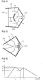
- FIG. 1 is a graph showing results of a test performed using a conventional side airbag unit
- FIG. 2 is a schematic sectional view of an airbag unit according to an embodiment of the present invention.
- FIG. 3 is a schematic diagram for explaining a blocking member and first through third tethers of the airbag unit illustrated in FIG. 2 , according to an embodiment of the present invention
- FIGS. 4 and 5 are schematic diagrams for explaining how the blocking member functions when an airbag member of the airbag unit illustrated in FIG. 2 inflates, according to an embodiment of the present invention.
- FIG.6 is a graph illustrating results of a test performed using the airbag unit illustrated in FIG. 2 .
- FIG. 2 is a schematic sectional view of an airbag unit 11 according to an embodiment of the present invention.
- a reference numeral 10 denotes a portion of a dummy that is used for pretending a vehicle occupant
- a reference numeral 20 denotes a side of a vehicle including the airbag unit 11.
- the airbag unit 11 includes an airbag member 21.
- a vent hole 21a is formed in one side of the airbag member 21.
- a gas generator is included in the airbag unit 11 on a side of the 3 airbag member 21. The gas generator (not shown) generates an inflation gas and the airbag member 21 may be inflated by the inflation gas.
- a blocking member 22 is provided to controllably block the vent hole 21a of the airbag member 21.
- the blocking member 22 is deployed in such a way that during inflation, the blocking member 22 is arranged inside the airbag member 21 to face the vent hole 21 a.
- the blocking member 22 is fixed with first through third tethers 23a, 23b, and 23c.
- the first through third tethers 23a, 23b, and 23c extend between predetermined points of the blocking member 22 and predetermined points of an inner surface of the airbag member 21.
- the first through third tethers 23a, 23b, and 23c may be fixed to the blocking member 22 and the airbag member 21 by stitching.
- a reference numeral 25 denotes points at which the first tether 23a is fixed to the airbag member 21
- a reference numeral 26 denotes points at which the first tether 23a is fixed to the blocking member 22.
- a reference numeral 27 denotes a point at which the second tether 23b is fixed to the blocking member 22, that is, a central point of the blocking member 22, and a reference numeral 28 denotes a point at which the second tether 23b is fixed to the third tether 23c.
- a reference numeral 29 denotes points at which ends of the third tether 23c are fixed to the blocking member 22.
- FIG. 3 is a schematic diagram for explaining the blocking member, 22 and the first through third tethers 23a, 23b, and 23c illustrated in FIG. 2 .
- the blocking member 22 may be formed of fabric, and the first through third tethers 23a, 23b, and 23c are used to fix the blocking member 22 to the airbag member 21.
- the blocking member 22 is tetragonal and is connected to the first tether 23a at a corner 26 of the blocking member 22.
- four first tethers 23a are provided.
- An end of the second tether 23b is connected to the central point 27 of the blocking member 22.
- Another end of the second tether 23b connected to the central point 27 of the blocking member 22 is connected to a central point of the third tether 23c. Ends of the first through third tethers 23a, 23b, and 23c are, as illustrated in FIG. 2 , fixed to the inner surface of the airbag member 21.
- the shape of the blocking member 22 is not limited thereto.
- the blocking member 22 may be, for example, triangular, pentagonal, hexagonal, or circular.
- the first tether 23a may comprise two or more tethers.
- two first tethers 23a may be fixed to two points separated by an angle of 180° on a circumference of the circular blocking member 22, respectively.
- each of the first tethers 23a fixed may consist of two or more tethers.
- FIGS. 4 and 5 are schematic diagrams for explaining how the blocking member 22 functions when the airbag member 21 inflates.
- FIG. 4 is a schematic diagram illustrating a state in which the airbag unit 11 inflates.
- the airbag member 21 is fully inflated by an inflation gas generated by a gas generator (not shown).
- the blocking member 22 is separated from the vent hole 21a by a predetermined distance, and thus, the blocking member 22 does not prevent the inflation gas from being discharged through the vent hole 21 a.
- a reference numeral 41 denotes a flow of the inflation gas, and due to the gas flow 41, while the airbag member 21 may be fully inflated, a portion of the inflation gas may be discharged through the vent hole 21a.
- the blocking member 22 does not block the vent hole 21a because the blocking member 22 is separated from the vent hole 21a by the second tether 23b extending from the central point of the blocking member 22 and the third tether 23c connected to the second tether 23b. That is, when the airbag member 21 initially inflates, a vehicle occupant does not yet push the airbag member 21 and thus, the airbag member 21 may be fully inflated. In this case, the third tether 23c fully extends in a thickness direction of the airbag member 21 corresponding to a distance between the side of the vehicle and the vehicle occupant. That is, as illustrated in FIG.
- the third tether 23c fully extends in a direction perpendicular to a direction of the gas flow 41 towards the vent hole 21a, and the third tether 23c is almost straight. Accordingly, the third tether 23c pulls the second tether 23b and thus the blocking member 22 is separated from the vent hole 21a.
- FIG. 5 is a schematic diagram illustrating a state in which the vehicle occupant pushes the inflated airbag member 21.
- the vehicle occupant pushes the airbag member 21 in reaction to an impact force generated when the vehicle collides.
- the thickness of the airbag member 21 is reduced compared to when fully inflated. That is, the thickness of the airbag member 21 that is once inflated is reduced and the third tether 23c becomes bent as illustrated in FIG. 5 , and thus the second tether 23b is moved towards the vent hole 21a.
- the blocking member 22 fixed to the end of the second tether 23b is moved closer to the vent hole 21a.
- the blocking member 22 may appropriately block the vent hole 21a depending on the lengths of the first through third tethers 23a, 23b, and 23c.
- 'a' denotes a distance between the point 25 at which the first tether 23a is fixed to the inner surface of the airbag member 21 and the central point 27 of the blocking member 22
- 'b' denotes a distance between the point 25 at which the first tether 23a is fixed to the inner surface of the airbag member 21 and the vent hole 21a.
- the distance 'b' between the point 25 and the vent hole 21a may be greater than the distance 'a' between the point 25 and the central point 27 of the blocking member 22 (a ⁇ b).
- the length of the first tether 23a may be adjusted to satisfy this condition and according to the length of the first tether 23a, lengths of the second tether 23b and the third tether 23c may be determined.
- the blocking member 22 may not completely block the vent hole 21a at an inappropriate time. That is, the inflation gas needs to be sufficiently and appropriately discharged when the weight of the vehicle occupant is applied to the airbag member 21.
- the vent hole 21a is blocked by the blocking member 22 when the vehicle occupant forcibly collides with the inflated airbag member 21, the vehicle occupant may be injured.
- the condition of a ⁇ b is satisfied, the complete blocking by the blocking member 22 may be prevented.
- FIG. 6 is a graph illustrating results of a test performed using the airbag unit 11 illustrated in FIGS. 2 through 5 .
- the x-axis represents time and the y-axis represents a rib deformity degree when pressure is applied to a vehicle occupant (dummy).
- the airbag member 21 is fully inflated and the inflated airbag member 21 pushes the vehicle occupant and thus, the rib deformity degree increases to d1'. Then, an inflation gas is discharged through the vent hole 21a formed in the airbag member 21 and thus, the airbag member 21 applies less pressure to the vehicle occupant. At t2', the rib deformity degree is reduced to d2'. After t2', as described above, the vent hole 21a is partially blocked by the blocking member 22.
- the inflation gas remains in the airbag member 21 and thus, although the rib deformity degree increases to d3', the difference between d2' and d3' is not significant. Thus, until the impact force due to collision of the vehicle completely disappears, the rib deformity degree does not increase any more and thus the potential for injury of the vehicle occupant is reduced.
- a vent hole formed in an airbag member is controllably blocked. By doing so, the potential for injury of a vehicle occupant can be minimized.
Landscapes
- Engineering & Computer Science (AREA)
- Mechanical Engineering (AREA)
- Air Bags (AREA)
Description
- The present invention relates to a side airbag unit for vehicles, and more particularly, to an airbag unit that uses a blocking member to partially block a vent hole formed in an airbag member when the airbag member inflates, so as to control inflation and deflation of the airbag member.
- Conventionally, vehicles include airbag units for protecting vehicle occupants in collisions. Airbag units include front airbag units and side airbag units. Front airbag units are installed in front of the driver's seat and front passenger seat. Side airbag units are installed at either side of the vehicle door.
- Conventionally, airbag units include a gas generator and an airbag member. When vehicles collide with other vehicles or other objects, a collision detection sensor transmits a signal to an electron control unit (ECU) and the ECU operates the gas generator and thus the gas generator generates an inflation gas, thereby inflating the airbag member. In collisions, vehicle occupants may forcibly collide with interior structures. To reduce the resultant impacts, the airbag member needs to be deflated to a predetermined degree after being rapidly inflated by the inflation gas. That is because if the airbag member is not deflated, vehicle occupants may forcibly collide with the inflated airbag member and thus become injured by the inflated airbag member. The deflation of the airbag member is performed by discharging the inflation gas filled in the airbag member. To discharge the inflation gas, a vent hole is formed in the airbag member.
-
FIG. 1 is a graph showing results of a test performed using a conventional side airbag unit. InFIG. 1 , the x-axis represents time and the y-axis represents a rib deformity degree when pressure is applied to a vehicle occupant. This test was performed using a dummy. - Referring to
FIG. 1 , an airbag member fully inflates at t1 and the dummy is pressed against the inflated airbag member and thus the rib deformity degree is increased to d1. Then, an inflation gas is discharged through a vent hole formed in the airbag member, and thus, the airbag member applies less pressure to the dummy, and thus at t2, the rib deformity degree is reduced to d2. After t2, the inflation gas continues to be discharged through the vent hole. If an impact force generated by a vehicle collision does not completely disappear even at t2, the dummy may continue to press against the airbag member and finally, the inflation gas may be completely discharged and the dummy 1 contacts a vehicle. As a result, at t3, the rib deformity degree increases to d3 and thus a vehicle occupant is highly likely to be injured. - As described above, when only a vent hole is formed in an airbag member without separate control members, the potential of injury to vehicle occupants caused by collision with the completely inflated airbag member can be reduced, but if an inflation gas is excessively discharged, the potential of injury to vehicle occupants may be increased.
- The prior art in
US 2004/0012179 A1 discloses an airbag unit comprising a gas generator, an airbag member that is inflatable by the gas generator and comprises two vent holes in the sides of the airbag member, blocking members that partially block the vent holes of the airbag member being deployed inside or outside the airbag member and a plurality of tethers connecting the blocking member to the airbag member. According toUS 2004/0012179 A1 , the operative lengths of the tethers maybe shortened by drawing a portion of the tethers towards an anchoring structure remote from the airbag cushion. Such a shortening in the operative lengths of the tethers causes the depth of the airbag cushion to be restrained. The tethers may furthermore be released from the anchoring position, whereby the operative lengths of the tethers is increased, thus, permitting the inflatable airbag member to assume an expanded profile or enhanced depths. This expended profile or enhanced depth is desirable if the physical character and orientation of the occupant in combination with the nature of the impact require an according inflation profile of the airbag member. Furthermore, according toUS 2004/0012179 A1 , the release of the tethers from the anchoring position also causes further parts of the tethers to activate the vent holes in the sides of the airbag member. Thereby, the vent holes may either be opened or closed, in order to influence the inflation and or deflation characteristic of the airbag member. - The present invention provides an airbag unit providing a high level of safety.
- The present invention also provides an airbag unit capable of controlling discharge of an inflation gas.
- The present invention also provides an airbag unit including a blocking member capable of controllably and partially blocking a vent hole.
- According to an aspect of the present invention, there is provided an airbag unit comprising:
- a gas generator;
- an airbag member that is inflatable by the gas generator and comprises a vent hole in one side of the airbag member;
- a blocking member that partially blocks the vent hole of the airbag member and is deployed inside the airbag member;
- a plurality of tethers connecting the blocking member to the airbag member;
- the plurality of tethers comprise first through third tethers, wherein the first connects one side of the blocking member to an inner surface of the airbag member, the second tether connects a central point of the blocking member to a central point of the third tether; and
- the ends of the third tether being fixed to the inner surface of the airbag member in such a way that when the airbag member is fully inflated and a vehicle occupant does not push the airbag member the third tether fully extends in a direction perpendicular to the direction in which an inflation gas flows towards the vent hole of the airbag member so that the blocking member does not block the vent hole and that when the occupant presses against the airbag member, thereby reducing the thickness of the airbag member compared with its full inflation, the third tether becomes bent and thus the second tether is moved towards the vent hole so that the blocking member fixed to the end of the second tether is moved closer to the vent hole and partially blocks the vent hole.
- According to another aspect of the present invention, a distance (a) between a point at which the first tether is fixed to the inner surface of the airbag member and the vent hole is greater than a distance (b) between the point at which the first tether is fixed to the inner surface of the airbag member and the central point of the blocking member.
- According to another aspect of the present invention, the blocking member is tetragonal.
- According to another aspect of the present invention, the blocking member is tetragonal and the four corners of the blocking member are respectively connected by the four first tethers.
- In an airbag unit according to the present invention, a vent hole formed in an airbag member is controllably blocked. By doing so, the potential for injury of a vehicle occupant can be minimized.
- The above and other features and advantages of the present invention will become more apparent by describing in detail exemplary embodiments thereof with reference to the attached drawings in which:
-
FIG. 1 is a graph showing results of a test performed using a conventional side airbag unit; -
FIG. 2 is a schematic sectional view of an airbag unit according to an embodiment of the present invention; -
FIG. 3 is a schematic diagram for explaining a blocking member and first through third tethers of the airbag unit illustrated inFIG. 2 , according to an embodiment of the present invention; -
FIGS. 4 and 5 are schematic diagrams for explaining how the blocking member functions when an airbag member of the airbag unit illustrated inFIG. 2 inflates, according to an embodiment of the present invention; and -
FIG.6 is a graph illustrating results of a test performed using the airbag unit illustrated inFIG. 2 . - Hereinafter, embodiment of the present invention will be described in detail with reference to the attached drawings.
-
FIG. 2 is a schematic sectional view of anairbag unit 11 according to an embodiment of the present invention. - Referring to
FIG. 2 , areference numeral 10 denotes a portion of a dummy that is used for pretending a vehicle occupant, and areference numeral 20 denotes a side of a vehicle including theairbag unit 11. Theairbag unit 11 includes anairbag member 21. Avent hole 21a is formed in one side of theairbag member 21. Although not illustrated inFIG. 2 , a gas generator is included in theairbag unit 11 on a side of the 3airbag member 21. The gas generator (not shown) generates an inflation gas and theairbag member 21 may be inflated by the inflation gas. - According to an embodiment of the present invention, a blocking
member 22 is provided to controllably block thevent hole 21a of theairbag member 21. Referring toFIG. 2 , the blockingmember 22 is deployed in such a way that during inflation, the blockingmember 22 is arranged inside theairbag member 21 to face thevent hole 21 a. The blockingmember 22 is fixed with first throughthird tethers - The first through
third tethers member 22 and predetermined points of an inner surface of theairbag member 21. The first throughthird tethers member 22 and theairbag member 21 by stitching. Referring toFIG. 2 , areference numeral 25 denotes points at which thefirst tether 23a is fixed to theairbag member 21, and areference numeral 26 denotes points at which thefirst tether 23a is fixed to the blockingmember 22. Areference numeral 27 denotes a point at which thesecond tether 23b is fixed to the blockingmember 22, that is, a central point of the blockingmember 22, and areference numeral 28 denotes a point at which thesecond tether 23b is fixed to thethird tether 23c. Areference numeral 29 denotes points at which ends of thethird tether 23c are fixed to the blockingmember 22. -
FIG. 3 is a schematic diagram for explaining the blocking member, 22 and the first throughthird tethers FIG. 2 . - Referring to
FIG. 3 , the blockingmember 22 may be formed of fabric, and the first throughthird tethers member 22 to theairbag member 21. In the embodiment illustrated inFIG. 3 , the blockingmember 22 is tetragonal and is connected to thefirst tether 23a at acorner 26 of the blockingmember 22. In this case, fourfirst tethers 23a are provided. An end of thesecond tether 23b is connected to thecentral point 27 of the blockingmember 22. Another end of thesecond tether 23b connected to thecentral point 27 of the blockingmember 22 is connected to a central point of thethird tether 23c. Ends of the first throughthird tethers FIG. 2 , fixed to the inner surface of theairbag member 21. - Although the blocking
member 22 illustrated inFIG. 3 is tetragonal, the shape of the blockingmember 22 is not limited thereto. For example, the blockingmember 22 may be, for example, triangular, pentagonal, hexagonal, or circular. In addition, thefirst tether 23a may comprise two or more tethers. For example, if the blockingmember 22 is circular, twofirst tethers 23a may be fixed to two points separated by an angle of 180° on a circumference of thecircular blocking member 22, respectively. Even when the blockingmember 22 has other shapes, each of thefirst tethers 23a fixed may consist of two or more tethers. -
FIGS. 4 and 5 are schematic diagrams for explaining how the blockingmember 22 functions when theairbag member 21 inflates. -
FIG. 4 is a schematic diagram illustrating a state in which theairbag unit 11 inflates. Referring toFIG. 4 , theairbag member 21 is fully inflated by an inflation gas generated by a gas generator (not shown). In this case, the blockingmember 22 is separated from thevent hole 21a by a predetermined distance, and thus, the blockingmember 22 does not prevent the inflation gas from being discharged through thevent hole 21 a. Areference numeral 41 denotes a flow of the inflation gas, and due to thegas flow 41, while theairbag member 21 may be fully inflated, a portion of the inflation gas may be discharged through thevent hole 21a. - The blocking
member 22 does not block thevent hole 21a because the blockingmember 22 is separated from thevent hole 21a by thesecond tether 23b extending from the central point of the blockingmember 22 and thethird tether 23c connected to thesecond tether 23b. That is, when theairbag member 21 initially inflates, a vehicle occupant does not yet push theairbag member 21 and thus, theairbag member 21 may be fully inflated. In this case, thethird tether 23c fully extends in a thickness direction of theairbag member 21 corresponding to a distance between the side of the vehicle and the vehicle occupant. That is, as illustrated inFIG. 4 , thethird tether 23c fully extends in a direction perpendicular to a direction of thegas flow 41 towards thevent hole 21a, and thethird tether 23c is almost straight. Accordingly, thethird tether 23c pulls thesecond tether 23b and thus the blockingmember 22 is separated from thevent hole 21a. -
FIG. 5 is a schematic diagram illustrating a state in which the vehicle occupant pushes theinflated airbag member 21. The vehicle occupant pushes theairbag member 21 in reaction to an impact force generated when the vehicle collides. Thus, the thickness of theairbag member 21 is reduced compared to when fully inflated. That is, the thickness of theairbag member 21 that is once inflated is reduced and thethird tether 23c becomes bent as illustrated inFIG. 5 , and thus thesecond tether 23b is moved towards thevent hole 21a. Thus, the blockingmember 22 fixed to the end of thesecond tether 23b is moved closer to thevent hole 21a. As a result, the blockingmember 22 may appropriately block thevent hole 21a depending on the lengths of the first throughthird tethers - Referring to
FIG. 2 , 'a' denotes a distance between thepoint 25 at which thefirst tether 23a is fixed to the inner surface of theairbag member 21 and thecentral point 27 of the blockingmember 22, and 'b' denotes a distance between thepoint 25 at which thefirst tether 23a is fixed to the inner surface of theairbag member 21 and thevent hole 21a. The distance 'b' between thepoint 25 and thevent hole 21a may be greater than the distance 'a' between thepoint 25 and thecentral point 27 of the blocking member 22 (a < b). The length of thefirst tether 23a may be adjusted to satisfy this condition and according to the length of thefirst tether 23a, lengths of thesecond tether 23b and thethird tether 23c may be determined. By controlling the distance 'b' between thepoint 25 and thevent hole 21a to be greater than the distance 'a' between thepoint 25 and thecentral point 27 of the blockingmember 22, the blockingmember 22 may not completely block thevent hole 21a at an inappropriate time. That is, the inflation gas needs to be sufficiently and appropriately discharged when the weight of the vehicle occupant is applied to theairbag member 21. However, if thevent hole 21a is blocked by the blockingmember 22 when the vehicle occupant forcibly collides with theinflated airbag member 21, the vehicle occupant may be injured. Thus, when the condition of a < b is satisfied, the complete blocking by the blockingmember 22 may be prevented. -
FIG. 6 is a graph illustrating results of a test performed using theairbag unit 11 illustrated inFIGS. 2 through 5 . InFIG. 6 , the x-axis represents time and the y-axis represents a rib deformity degree when pressure is applied to a vehicle occupant (dummy). - Referring to
FIG. 6 , at t1' after theairbag member 21 begins to inflate, theairbag member 21 is fully inflated and theinflated airbag member 21 pushes the vehicle occupant and thus, the rib deformity degree increases to d1'. Then, an inflation gas is discharged through thevent hole 21a formed in theairbag member 21 and thus, theairbag member 21 applies less pressure to the vehicle occupant. At t2', the rib deformity degree is reduced to d2'. After t2', as described above, thevent hole 21a is partially blocked by the blockingmember 22. Until t3', the inflation gas remains in theairbag member 21 and thus, although the rib deformity degree increases to d3', the difference between d2' and d3' is not significant. Thus, until the impact force due to collision of the vehicle completely disappears, the rib deformity degree does not increase any more and thus the potential for injury of the vehicle occupant is reduced. - In an airbag unit according to the present invention, a vent hole formed in an airbag member is controllably blocked. By doing so, the potential for injury of a vehicle occupant can be minimized.
Claims (4)
- An airbag unit (11) comprising:a gas generator;an airbag member (21) that is inflatable by the gas generator and comprisescharacterized in thata vent hole (21a) in one side of the airbag member;a blocking member (22) that partially blocks the vent hole (21a) of the airbag member (21) and is deployed inside the airbag member; anda plurality of tethers (23a, b, c) connecting the blocking member (22) to the airbag member (21),
the plurality of tethers comprise first through third tethers (23a, b, c), wherein the first (23a) connects one side of the blocking member (22) to an inner surface of the airbag member (21),
the second tether (23b) connects a central point (27) of the blocking member (22) to a central point (28) of the third tether (23c),
the ends of the third tether (23c) being fixed to the inner surface of the airbag member (21) in such a way that when the airbag member (21) is fully inflated and a vehicle occupant does not push the airbag member (21) the third tether (23c) fully extends in a direction perpendicular to the direction in which an inflation gas flows towards the vent hole (21a) of the airbag member (21) so that the blocking member (22) does not block the vent hole (21a)
and that when the occupant presses against the airbag member (21), thereby reducing the thickness of the airbag member (21) compared with its full inflation
the third tether (23c) becomes bent and thus the second tether (23) is moved towards the vent hole (21a)
so that the blocking member (22) fixed to the end of the second tether (23b) is moved closer to the vent hole (21a) and partially blocks the vent hole (21a). - The airbag unit according to claim 1, characterized, that a distance (a) between a point at which the first tether (23a) is fixed to the inner surface of the airbag member (21) and the vent hole (21a) is greater than a distance (b) between the point (25) at which the first tether (23a) is fixed to the inner surface of the airbag member (21) and the central point (27) of the blocking member (22).
- The airbag unit according to claim 1 or 2, characterized in that the blocking member (22) is tetragonal.
- The airbag unit according to claim 1 or 2, characterized in that the blocking member (22) is tetragonal and the four corners (26) of the blocking member (22) are respectively connected by the four first tethers (23 a).
Applications Claiming Priority (2)
| Application Number | Priority Date | Filing Date | Title |
|---|---|---|---|
| KR1020090039763A KR101688955B1 (en) | 2009-05-07 | 2009-05-07 | Side Air-bag unit for Vehicle |
| PCT/KR2010/002856 WO2010128799A2 (en) | 2009-05-07 | 2010-05-06 | Side airbag unit for vehicle |
Publications (3)
| Publication Number | Publication Date |
|---|---|
| EP2427351A2 EP2427351A2 (en) | 2012-03-14 |
| EP2427351A4 EP2427351A4 (en) | 2012-10-17 |
| EP2427351B1 true EP2427351B1 (en) | 2013-11-13 |
Family
ID=43050624
Family Applications (1)
| Application Number | Title | Priority Date | Filing Date |
|---|---|---|---|
| EP10772259.7A Active EP2427351B1 (en) | 2009-05-07 | 2010-05-06 | Side airbag unit for vehicle |
Country Status (3)
| Country | Link |
|---|---|
| EP (1) | EP2427351B1 (en) |
| KR (1) | KR101688955B1 (en) |
| WO (1) | WO2010128799A2 (en) |
Families Citing this family (1)
| Publication number | Priority date | Publication date | Assignee | Title |
|---|---|---|---|---|
| FR2993223A1 (en) * | 2012-07-12 | 2014-01-17 | Peugeot Citroen Automobiles Sa | Airbag safety device for car, has airbag including control unit to control access to opening according to airbag depression, where access is restricted when depression is large to vary stiffness of airbag depending on depression |
Family Cites Families (5)
| Publication number | Priority date | Publication date | Assignee | Title |
|---|---|---|---|---|
| KR100286984B1 (en) * | 1998-09-14 | 2001-04-16 | 이승복 | Cushion of air bag for passenger |
| JP2001151059A (en) * | 1999-11-22 | 2001-06-05 | Toyoda Gosei Co Ltd | Air bag for air bag device |
| JP2002104119A (en) * | 2000-09-28 | 2002-04-10 | Nippon Plast Co Ltd | Air bag device for automobile |
| US6832778B2 (en) * | 2002-07-19 | 2004-12-21 | Delphi Technologies, Inc. | Air bag restraint including selectively operable venting elements |
| JP5186832B2 (en) * | 2007-08-09 | 2013-04-24 | タカタ株式会社 | Air bag and air bag device |
-
2009
- 2009-05-07 KR KR1020090039763A patent/KR101688955B1/en not_active Expired - Fee Related
-
2010
- 2010-05-06 EP EP10772259.7A patent/EP2427351B1/en active Active
- 2010-05-06 WO PCT/KR2010/002856 patent/WO2010128799A2/en not_active Ceased
Also Published As
| Publication number | Publication date |
|---|---|
| KR101688955B1 (en) | 2016-12-22 |
| WO2010128799A3 (en) | 2011-03-10 |
| KR20100120897A (en) | 2010-11-17 |
| EP2427351A2 (en) | 2012-03-14 |
| EP2427351A4 (en) | 2012-10-17 |
| WO2010128799A2 (en) | 2010-11-11 |
Similar Documents
| Publication | Publication Date | Title |
|---|---|---|
| EP1997695B1 (en) | Airbag device | |
| US7581749B2 (en) | Integrated airbag panel | |
| US7261320B2 (en) | Airbag cushion with dual mode deployment for pre-impact and impact conditions | |
| US20070108745A1 (en) | Side impact airbag | |
| JP4193854B2 (en) | Airbag device for vehicle | |
| WO2008060808A2 (en) | Inflatable pusher | |
| JP4999843B2 (en) | Side airbag unit for automobile | |
| KR20090114850A (en) | Car Side Air Bag | |
| JP4931512B2 (en) | Airbag device for passenger seat | |
| KR20160017997A (en) | Passenger Airbag Aparatus Of Vehicle | |
| US20100171295A1 (en) | Driver's air bag | |
| US12296780B2 (en) | Front airbag for a vehicle occupant, vehicle occupant protection system, and method for operating a vehicle occupant protection system | |
| JP3500915B2 (en) | Airbag for side impact | |
| KR20180062494A (en) | Front airbag for vehicle | |
| KR101594772B1 (en) | Airbag device | |
| KR101688955B1 (en) | Side Air-bag unit for Vehicle | |
| US9573552B2 (en) | Delay orifice opening | |
| KR20100099550A (en) | Passenger air-bag for a vehicle | |
| KR100512427B1 (en) | Airbag in vehicle | |
| KR100380401B1 (en) | Decompression type air bag for automobiles | |
| JPH0542855A (en) | Air bag structure of automobile | |
| KR19990005093U (en) | Car airbag structure | |
| KR200400959Y1 (en) | airbag assembly | |
| KR100559894B1 (en) | Deployment Shock Absorber of Vehicle Curtain Air Bag | |
| KR100643585B1 (en) | Car Airbag Cushion |
Legal Events
| Date | Code | Title | Description |
|---|---|---|---|
| PUAI | Public reference made under article 153(3) epc to a published international application that has entered the european phase |
Free format text: ORIGINAL CODE: 0009012 |
|
| 17P | Request for examination filed |
Effective date: 20111103 |
|
| AK | Designated contracting states |
Kind code of ref document: A2 Designated state(s): AL AT BE BG CH CY CZ DE DK EE ES FI FR GB GR HR HU IE IS IT LI LT LU LV MC MK MT NL NO PL PT RO SE SI SK SM TR |
|
| DAX | Request for extension of the european patent (deleted) | ||
| A4 | Supplementary search report drawn up and despatched |
Effective date: 20120919 |
|
| RIC1 | Information provided on ipc code assigned before grant |
Ipc: B60R 21/20 20110101ALI20120912BHEP Ipc: B60R 21/21 20110101AFI20120912BHEP Ipc: B60R 21/16 20060101ALI20120912BHEP |
|
| GRAP | Despatch of communication of intention to grant a patent |
Free format text: ORIGINAL CODE: EPIDOSNIGR1 |
|
| INTG | Intention to grant announced |
Effective date: 20130603 |
|
| GRAS | Grant fee paid |
Free format text: ORIGINAL CODE: EPIDOSNIGR3 |
|
| GRAA | (expected) grant |
Free format text: ORIGINAL CODE: 0009210 |
|
| AK | Designated contracting states |
Kind code of ref document: B1 Designated state(s): AL AT BE BG CH CY CZ DE DK EE ES FI FR GB GR HR HU IE IS IT LI LT LU LV MC MK MT NL NO PL PT RO SE SI SK SM TR |
|
| REG | Reference to a national code |
Ref country code: GB Ref legal event code: FG4D |
|
| REG | Reference to a national code |
Ref country code: CH Ref legal event code: EP |
|
| REG | Reference to a national code |
Ref country code: AT Ref legal event code: REF Ref document number: 640432 Country of ref document: AT Kind code of ref document: T Effective date: 20131215 |
|
| REG | Reference to a national code |
Ref country code: IE Ref legal event code: FG4D |
|
| REG | Reference to a national code |
Ref country code: DE Ref legal event code: R096 Ref document number: 602010011748 Country of ref document: DE Effective date: 20140109 |
|
| REG | Reference to a national code |
Ref country code: NL Ref legal event code: VDEP Effective date: 20131113 |
|
| REG | Reference to a national code |
Ref country code: AT Ref legal event code: MK05 Ref document number: 640432 Country of ref document: AT Kind code of ref document: T Effective date: 20131113 |
|
| REG | Reference to a national code |
Ref country code: LT Ref legal event code: MG4D |
|
| PG25 | Lapsed in a contracting state [announced via postgrant information from national office to epo] |
Ref country code: LT Free format text: LAPSE BECAUSE OF FAILURE TO SUBMIT A TRANSLATION OF THE DESCRIPTION OR TO PAY THE FEE WITHIN THE PRESCRIBED TIME-LIMIT Effective date: 20131113 Ref country code: NL Free format text: LAPSE BECAUSE OF FAILURE TO SUBMIT A TRANSLATION OF THE DESCRIPTION OR TO PAY THE FEE WITHIN THE PRESCRIBED TIME-LIMIT Effective date: 20131113 Ref country code: SE Free format text: LAPSE BECAUSE OF FAILURE TO SUBMIT A TRANSLATION OF THE DESCRIPTION OR TO PAY THE FEE WITHIN THE PRESCRIBED TIME-LIMIT Effective date: 20131113 Ref country code: FI Free format text: LAPSE BECAUSE OF FAILURE TO SUBMIT A TRANSLATION OF THE DESCRIPTION OR TO PAY THE FEE WITHIN THE PRESCRIBED TIME-LIMIT Effective date: 20131113 Ref country code: NO Free format text: LAPSE BECAUSE OF FAILURE TO SUBMIT A TRANSLATION OF THE DESCRIPTION OR TO PAY THE FEE WITHIN THE PRESCRIBED TIME-LIMIT Effective date: 20140213 Ref country code: HR Free format text: LAPSE BECAUSE OF FAILURE TO SUBMIT A TRANSLATION OF THE DESCRIPTION OR TO PAY THE FEE WITHIN THE PRESCRIBED TIME-LIMIT Effective date: 20131113 Ref country code: IS Free format text: LAPSE BECAUSE OF FAILURE TO SUBMIT A TRANSLATION OF THE DESCRIPTION OR TO PAY THE FEE WITHIN THE PRESCRIBED TIME-LIMIT Effective date: 20140313 |
|
| PG25 | Lapsed in a contracting state [announced via postgrant information from national office to epo] |
Ref country code: AT Free format text: LAPSE BECAUSE OF FAILURE TO SUBMIT A TRANSLATION OF THE DESCRIPTION OR TO PAY THE FEE WITHIN THE PRESCRIBED TIME-LIMIT Effective date: 20131113 Ref country code: BE Free format text: LAPSE BECAUSE OF FAILURE TO SUBMIT A TRANSLATION OF THE DESCRIPTION OR TO PAY THE FEE WITHIN THE PRESCRIBED TIME-LIMIT Effective date: 20131113 Ref country code: ES Free format text: LAPSE BECAUSE OF FAILURE TO SUBMIT A TRANSLATION OF THE DESCRIPTION OR TO PAY THE FEE WITHIN THE PRESCRIBED TIME-LIMIT Effective date: 20131113 Ref country code: LV Free format text: LAPSE BECAUSE OF FAILURE TO SUBMIT A TRANSLATION OF THE DESCRIPTION OR TO PAY THE FEE WITHIN THE PRESCRIBED TIME-LIMIT Effective date: 20131113 Ref country code: CY Free format text: LAPSE BECAUSE OF FAILURE TO SUBMIT A TRANSLATION OF THE DESCRIPTION OR TO PAY THE FEE WITHIN THE PRESCRIBED TIME-LIMIT Effective date: 20131113 |
|
| PG25 | Lapsed in a contracting state [announced via postgrant information from national office to epo] |
Ref country code: PT Free format text: LAPSE BECAUSE OF FAILURE TO SUBMIT A TRANSLATION OF THE DESCRIPTION OR TO PAY THE FEE WITHIN THE PRESCRIBED TIME-LIMIT Effective date: 20140313 |
|
| PG25 | Lapsed in a contracting state [announced via postgrant information from national office to epo] |
Ref country code: EE Free format text: LAPSE BECAUSE OF FAILURE TO SUBMIT A TRANSLATION OF THE DESCRIPTION OR TO PAY THE FEE WITHIN THE PRESCRIBED TIME-LIMIT Effective date: 20131113 |
|
| REG | Reference to a national code |
Ref country code: DE Ref legal event code: R097 Ref document number: 602010011748 Country of ref document: DE |
|
| PG25 | Lapsed in a contracting state [announced via postgrant information from national office to epo] |
Ref country code: SK Free format text: LAPSE BECAUSE OF FAILURE TO SUBMIT A TRANSLATION OF THE DESCRIPTION OR TO PAY THE FEE WITHIN THE PRESCRIBED TIME-LIMIT Effective date: 20131113 Ref country code: RO Free format text: LAPSE BECAUSE OF FAILURE TO SUBMIT A TRANSLATION OF THE DESCRIPTION OR TO PAY THE FEE WITHIN THE PRESCRIBED TIME-LIMIT Effective date: 20131113 Ref country code: CZ Free format text: LAPSE BECAUSE OF FAILURE TO SUBMIT A TRANSLATION OF THE DESCRIPTION OR TO PAY THE FEE WITHIN THE PRESCRIBED TIME-LIMIT Effective date: 20131113 Ref country code: PL Free format text: LAPSE BECAUSE OF FAILURE TO SUBMIT A TRANSLATION OF THE DESCRIPTION OR TO PAY THE FEE WITHIN THE PRESCRIBED TIME-LIMIT Effective date: 20131113 |
|
| PLBE | No opposition filed within time limit |
Free format text: ORIGINAL CODE: 0009261 |
|
| STAA | Information on the status of an ep patent application or granted ep patent |
Free format text: STATUS: NO OPPOSITION FILED WITHIN TIME LIMIT |
|
| PG25 | Lapsed in a contracting state [announced via postgrant information from national office to epo] |
Ref country code: DK Free format text: LAPSE BECAUSE OF FAILURE TO SUBMIT A TRANSLATION OF THE DESCRIPTION OR TO PAY THE FEE WITHIN THE PRESCRIBED TIME-LIMIT Effective date: 20131113 |
|
| 26N | No opposition filed |
Effective date: 20140814 |
|
| REG | Reference to a national code |
Ref country code: DE Ref legal event code: R097 Ref document number: 602010011748 Country of ref document: DE Effective date: 20140814 |
|
| PG25 | Lapsed in a contracting state [announced via postgrant information from national office to epo] |
Ref country code: LU Free format text: LAPSE BECAUSE OF FAILURE TO SUBMIT A TRANSLATION OF THE DESCRIPTION OR TO PAY THE FEE WITHIN THE PRESCRIBED TIME-LIMIT Effective date: 20140506 |
|
| REG | Reference to a national code |
Ref country code: CH Ref legal event code: PL |
|
| GBPC | Gb: european patent ceased through non-payment of renewal fee |
Effective date: 20140506 |
|
| PG25 | Lapsed in a contracting state [announced via postgrant information from national office to epo] |
Ref country code: LI Free format text: LAPSE BECAUSE OF NON-PAYMENT OF DUE FEES Effective date: 20140531 Ref country code: CH Free format text: LAPSE BECAUSE OF NON-PAYMENT OF DUE FEES Effective date: 20140531 Ref country code: MC Free format text: LAPSE BECAUSE OF FAILURE TO SUBMIT A TRANSLATION OF THE DESCRIPTION OR TO PAY THE FEE WITHIN THE PRESCRIBED TIME-LIMIT Effective date: 20131113 |
|
| REG | Reference to a national code |
Ref country code: IE Ref legal event code: MM4A |
|
| PG25 | Lapsed in a contracting state [announced via postgrant information from national office to epo] |
Ref country code: SI Free format text: LAPSE BECAUSE OF FAILURE TO SUBMIT A TRANSLATION OF THE DESCRIPTION OR TO PAY THE FEE WITHIN THE PRESCRIBED TIME-LIMIT Effective date: 20131113 |
|
| PG25 | Lapsed in a contracting state [announced via postgrant information from national office to epo] |
Ref country code: IE Free format text: LAPSE BECAUSE OF NON-PAYMENT OF DUE FEES Effective date: 20140506 Ref country code: IT Free format text: LAPSE BECAUSE OF FAILURE TO SUBMIT A TRANSLATION OF THE DESCRIPTION OR TO PAY THE FEE WITHIN THE PRESCRIBED TIME-LIMIT Effective date: 20131113 |
|
| PG25 | Lapsed in a contracting state [announced via postgrant information from national office to epo] |
Ref country code: GB Free format text: LAPSE BECAUSE OF NON-PAYMENT OF DUE FEES Effective date: 20140506 |
|
| PG25 | Lapsed in a contracting state [announced via postgrant information from national office to epo] |
Ref country code: MT Free format text: LAPSE BECAUSE OF FAILURE TO SUBMIT A TRANSLATION OF THE DESCRIPTION OR TO PAY THE FEE WITHIN THE PRESCRIBED TIME-LIMIT Effective date: 20131113 |
|
| PG25 | Lapsed in a contracting state [announced via postgrant information from national office to epo] |
Ref country code: SM Free format text: LAPSE BECAUSE OF FAILURE TO SUBMIT A TRANSLATION OF THE DESCRIPTION OR TO PAY THE FEE WITHIN THE PRESCRIBED TIME-LIMIT Effective date: 20131113 |
|
| REG | Reference to a national code |
Ref country code: FR Ref legal event code: PLFP Year of fee payment: 7 |
|
| PG25 | Lapsed in a contracting state [announced via postgrant information from national office to epo] |
Ref country code: BG Free format text: LAPSE BECAUSE OF FAILURE TO SUBMIT A TRANSLATION OF THE DESCRIPTION OR TO PAY THE FEE WITHIN THE PRESCRIBED TIME-LIMIT Effective date: 20131113 Ref country code: GR Free format text: LAPSE BECAUSE OF FAILURE TO SUBMIT A TRANSLATION OF THE DESCRIPTION OR TO PAY THE FEE WITHIN THE PRESCRIBED TIME-LIMIT Effective date: 20140214 |
|
| PG25 | Lapsed in a contracting state [announced via postgrant information from national office to epo] |
Ref country code: TR Free format text: LAPSE BECAUSE OF FAILURE TO SUBMIT A TRANSLATION OF THE DESCRIPTION OR TO PAY THE FEE WITHIN THE PRESCRIBED TIME-LIMIT Effective date: 20131113 Ref country code: HU Free format text: LAPSE BECAUSE OF FAILURE TO SUBMIT A TRANSLATION OF THE DESCRIPTION OR TO PAY THE FEE WITHIN THE PRESCRIBED TIME-LIMIT; INVALID AB INITIO Effective date: 20100506 |
|
| REG | Reference to a national code |
Ref country code: FR Ref legal event code: PLFP Year of fee payment: 8 |
|
| REG | Reference to a national code |
Ref country code: FR Ref legal event code: PLFP Year of fee payment: 9 |
|
| PG25 | Lapsed in a contracting state [announced via postgrant information from national office to epo] |
Ref country code: MK Free format text: LAPSE BECAUSE OF FAILURE TO SUBMIT A TRANSLATION OF THE DESCRIPTION OR TO PAY THE FEE WITHIN THE PRESCRIBED TIME-LIMIT Effective date: 20131113 |
|
| PG25 | Lapsed in a contracting state [announced via postgrant information from national office to epo] |
Ref country code: AL Free format text: LAPSE BECAUSE OF FAILURE TO SUBMIT A TRANSLATION OF THE DESCRIPTION OR TO PAY THE FEE WITHIN THE PRESCRIBED TIME-LIMIT Effective date: 20131113 |
|
| PGFP | Annual fee paid to national office [announced via postgrant information from national office to epo] |
Ref country code: FR Payment date: 20220525 Year of fee payment: 13 |
|
| PG25 | Lapsed in a contracting state [announced via postgrant information from national office to epo] |
Ref country code: FR Free format text: LAPSE BECAUSE OF NON-PAYMENT OF DUE FEES Effective date: 20230531 |
|
| PGFP | Annual fee paid to national office [announced via postgrant information from national office to epo] |
Ref country code: DE Payment date: 20250528 Year of fee payment: 16 |