EP2427002B1 - Method, device and system for transmitting relay data - Google Patents
Method, device and system for transmitting relay data Download PDFInfo
- Publication number
- EP2427002B1 EP2427002B1 EP10769261.8A EP10769261A EP2427002B1 EP 2427002 B1 EP2427002 B1 EP 2427002B1 EP 10769261 A EP10769261 A EP 10769261A EP 2427002 B1 EP2427002 B1 EP 2427002B1
- Authority
- EP
- European Patent Office
- Prior art keywords
- relay
- radio access
- access bearer
- control signaling
- module
- Prior art date
- Legal status (The legal status is an assumption and is not a legal conclusion. Google has not performed a legal analysis and makes no representation as to the accuracy of the status listed.)
- Active
Links
Images




Classifications
-
- H—ELECTRICITY
- H04—ELECTRIC COMMUNICATION TECHNIQUE
- H04B—TRANSMISSION
- H04B7/00—Radio transmission systems, i.e. using radiation field
- H04B7/24—Radio transmission systems, i.e. using radiation field for communication between two or more posts
- H04B7/26—Radio transmission systems, i.e. using radiation field for communication between two or more posts at least one of which is mobile
- H04B7/2603—Arrangements for wireless physical layer control
- H04B7/2606—Arrangements for base station coverage control, e.g. by using relays in tunnels
-
- H—ELECTRICITY
- H04—ELECTRIC COMMUNICATION TECHNIQUE
- H04B—TRANSMISSION
- H04B7/00—Radio transmission systems, i.e. using radiation field
- H04B7/14—Relay systems
- H04B7/15—Active relay systems
- H04B7/155—Ground-based stations
-
- H—ELECTRICITY
- H04—ELECTRIC COMMUNICATION TECHNIQUE
- H04W—WIRELESS COMMUNICATION NETWORKS
- H04W84/00—Network topologies
- H04W84/02—Hierarchically pre-organised networks, e.g. paging networks, cellular networks, WLAN [Wireless Local Area Network] or WLL [Wireless Local Loop]
- H04W84/04—Large scale networks; Deep hierarchical networks
- H04W84/042—Public Land Mobile systems, e.g. cellular systems
- H04W84/047—Public Land Mobile systems, e.g. cellular systems using dedicated repeater stations
Definitions
- the present invention relates to communication field, and in particular to a method, a device and a system for transmitting relay data.
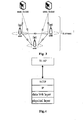
- Fig.1 is a schematic diagram of the structure of a cellular wireless communication system in prior art.
- the cellular wireless communication system mainly includes: a terminal (User Equipment, referred to as UE), an access network and a core network, wherein the terminal refers to various equipments which can communicate with the cellular wireless communication network, such as, mobile phone or notebook PC.
- the Radio Access Network refers to the network composed of a base station, or the network composed of a base station and a base station controller, and is mainly responsible for access stratum service, such as radio resource management.
- the core network is an anchor point of the user plane, and is mainly responsible for non-access stratum service, such as location update.
- Each of the base stations can connect one or more core network (CN) nodes.
- CN core network
- the wireless coverage of a fixed base station network will be restricted due to some reasons, such as, the blocking that building structure creates for radio signal caused will result in a coverage loophole for the wireless network.
- the communication quality of the UE at the cell edge area will be poorer, and error rate of wireless transmission will increase.
- a wireless network node which is referred to as relay node/relay station, is introduced in the cellular wireless communication system.
- the relay node (referred to as Relay below) has the function of relaying data and possible control information via a wireless link.
- Fig.2 is a schematic diagram of a network architecture including the relay in prior art.
- the UE directly served by a base station eNodeB, which can also be abbreviated to eNB
- eNB base station
- Relay UE the UE served by the Relay
- a direct link refers to the wireless link between the base station and the UE, which includes an uplink/downlink (UL/DL) direct link
- an access link refers to the wireless link between the Relay and the UE, which includes a DL/UL access link
- a backhaul link refers to the wireless link between the base station and the Relay, which includes a DL/UL relay link.
- the Relay to relay data, for example, amplifying directly the wireless signal received from a base station; or forwarding the correctly received data packet to the terminal after performing a corresponding process on the received data sent from the base station; or sending data to the terminal by the base station cooperating with the Relay, and also the Relay being used for relaying the data sent from the terminal to the base station.
- Fig.3 is a schematic diagram of flat structure of in related art.
- the IP (Internet Protocol)-based long term evolution (LTE) system consists of an E-UTRAN (Evolved Universal Terrestrial Radio Access Network), a CN node, and other support nodes, wherein the CN node includes a MME (Mobility Management Entity) and a S-GW (Serving Gateway), wherein the MME is responsible for control plane related tasks, such as mobility management, signaling processing in non-access stratum, and context management of mobility management for the UE; the S-GW is responsible for data transferring, retransmitting, and routing switching for the UE plane; the eNBs interconnect with each other via X2 interface in logic to support the mobility of the UE in the whole network, so as to ensure seamless switching of the UE; each eNB is connected to a SAE (System Architecture Evolution) core network via S 1 interface, that is to say, connected to MME via the control plane S1-MME
- SAE System Architecture
- Fig.4 is a schematic diagram of protocol stack of S1-MME interface in related art.
- the network layer of S1-MME interface employs IP protocol
- the transport layer above the network layer employs the SCTP protocol
- the application layer in uppermost layer that is S1-AP protocol of the control plane
- the layers below the network layer which employs IP-based S1-MME interface sequentially are the data link layer and the physical layer.
- Fig.5 is a schematic diagram of protocol stack of S1-U interface in related art.
- the User plane of GPRS (General Packet Radio Service) Tunneling Protocol (GTP-U)/User Datagram Protocol (UDP)/IP constitute transmission bearer for transmitting the user plane PDU (Protocol Data Unit) between the eNB and the S-GW.
- the transmission bearer is identified by tunnel endpoint identifiers (TEID) of the GTP-U including the source side GTP-U TEID and the target side GTP-U TEID, and IP addresses including the source side IP address and the target side IP address, wherein the UDP port number is fixed as 2152; the GTP-U is a tunneling protocol for implementing the seamless transmission on the IPv4 and the IPv6.
- TEID tunnel endpoint identifiers
- Each transmission bearer is used to carry service data flows.
- Each eNB performs the signaling and data transmission with the UE via a Uu interface (which is defined as the wireless interface between the UTRAN and the UE initially).
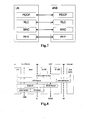
- Fig. 6 and Fig. 7 illustrate protocol stack of the air interface between the eNB and L1, L2, L3 of the UE respectively from the control plane and the UE plane.
- Fig.8 is a schematic diagram of the bearer structure of the LTE system in related art.
- the LTE system can provide end-to-end service, and ensure quality of service(QoS) of the provided service through the parameters carried particularly.
- the granularity ensured by the QoS level of the bearers of the Evolved Packet Core (EPC) and the E-UTRAN is EPS bearer/E-RAB (E-UTRAN Radio Access Bearer).
- Data packet carried by the EPS bearer is transmitted between the S-GW and PDN gateway (P-GW) via S5/S8 bearer.
- P-GW PDN gateway
- the data packet of the E-RAB is transmitted between the eNodeB and the S-GW via S1 Bearer, and transmitted between the UE and the eNodeB via radio bearer (RB).
- RB radio bearer
- NORTEL "One Tunnel and GGSN Bearer Relay: SGSN User Plane", 3GPP DRAFT; S2-061619_USER_PLANE_FINAL,3RD GENERATION PARTNERSHIP PROJECT (3GPP), MOBILE COMPETENCE CENTRE; 650,ROUTE DES LUCIOLES;F-06921 SOPHIA-ANTIPOLIS CEDEX; FRANCE, vol. SA WG2, no. Shanghai, China; 20060508-20060512, 3 May 2006 (2006-05-03), XP050626759, [retrieved on 2006-05-03 ] provides respective technical solutions. However, the above mentioned problem still remains unsolved.
- the present invention is provided in view of that there is no technical solution for a Relay node to relay data between a UE and a S-GW in existing LTE system.
- the present invention intends to provide a solution for transmitting the relay data, so as to solve the above problem.
- a method for transmitting relay data which is applied in a system comprising a relay node.
- the method for transmitting the relay data in accordance with the present invention comprises: a relay radio access bearer service between a relay node and a relay Serving Gateway (S-GW) is borne by a relay radio access bearer to relay the radio access bearer services of terminals.
- S-GW Serving Gateway
- the method further comprises: the relay node or the relay S-GW multiplexes the radio access bearer services of a plurality of terminals to obtain the relay radio access bearer service to be borne.
- the method further comprises: the relay S-GW receives the borne relay radio access bearer service, and demultiplexes the received relay radio access bearer service, to obtain the radio access bearer services of the multiple terminals.
- the method further comprises: the relay node receives the borne relay radio access bearer service, and demultiplexes the received relay radio access bearer service, to obtain the radio access bearer services needed to be sent to the multiple terminals.
- the above method further comprises one of the following: the relay node or the relay S-GW makes the user plane protocol address of tunneling protocol allocated to the radio bearer of the radio access bearer services, to be used as the identifier for multiplexing and/or demultiplexing; the relay node or the relay S-GW makes the identifier allocated to each radio access bearer to be used as the identifier for multiplexing and/or demultiplexing; and the relay node or the relay S-GW makes the tunnel endpoint identifier allocated to the radio bearer of the radio access bearer services to be used as the identifier for multiplexing and/or demultiplexing.
- the relay radio access bearer is also configured to transmit the S1-AP control signaling of the terminal on the user plane or the control plane.
- the step of the relay radio access bearer transmitting the S1-AP control signaling of the terminal on the user plane comprises: the relay node or the relay S-GW multiplexes the S1-AP control signaling of the multiple terminals according to respective S1-AP identifier, to obtain the relay radio access bearer service to be borne.
- the step of relay radio access bearer transmitting the S1-AP control signaling of the terminal on the control plane comprises: the S1-AP control signaling of the terminals is transmitted via a control plane direct transfer message of the relay radio access bearer, wherein the S1-AP control signaling of the multiple terminals according to a S1-AP identifier multiplexed as a part of the control plane direct transfer message of the relay radio access bearer, so as to be transmitted; and in the case that the relay node performs the multiplex operation, a core network mobility management entity performs a demultiplex operation; or in the case that the core network MME performs the multiplex operation, the relay node performs a demultiplex operation.
- a relay node there is provided a relay node.
- the relay node comprises: a first receiving module, configured to receive radio access bearer services from terminals; a second receiving module, configured to receive the relay radio access bearer service from a core network; a multiplexing module, configured to multiplex the S1-AP control signaling and/or the radio access bearer services of the multiple terminals received by the first receiving module; a de-multiplexing module, configured to demultiplex the multiplexed S1-AP control signaling and/or the radio access bearer services received by the second receiving module; a first transmitting module, configured to transmit, via a relay radio access bearer, to the S-GW the radio access bearer services and/or the S1-AP control signaling multiplexed by the multiplexing module; a second transmitting module, configured to transmit via a control plane the S1-AP control signaling multiplexed by the multiplexing module; and a third transmitting module, configured to send, via an air interface, to the terminal the demultiplexed radio access bearer services of the terminal.
- a relay serving gateway is provided.
- the relay serving gateway comprises: a receiving module, configured to receive the multiplexed S1-AP control signaling and/or the radio access bearer services from the relay node; a de-multiplexing module, configured to demultiplex the S1-AP control signaling and/or the radio access bearer services which are multiplexed and received by the receiving module; a multiplexing module, configured to multiplex the S1-AP control signaling and/or the radio access bearer services from the core network; a transmitting module, configured to transmit, via a relay radio access bearer, to the relay node the radio access bearer services and/or the S1-AP control signaling multiplexed by the multiplexing module.
- a mobility management network element is provided.
- the mobility management network element comprises: a receiving module, configured to receive the multiplexed S1-AP control signaling from the relay node; a de-multiplexing module, configured to demultiplex the multiplexed S1-AP control signaling received by the receiving module; a multiplexing module, configured to multiplex the plurality of S1-AP control signalings; and a transmitting module, configured to transmit, via a control plane direct transfer message, to the relay node the S1-AP control signaling multiplexed by the multiplex module.
- a system for transmitting the relay data is provided.
- the system for transmitting the relay data comprises: a relay node and a serving gateway, and/or a mobility management network element, wherein the relay node comprises: a first receiving module, configured to receive a S1-AP control signaling and radio access bearer services from a terminal; a second receiving module, configured to receive a relay radio access bearer service from the core network; a multiplexing module, configured to multiplex the S1-AP control signaling and/or the radio access bearer services of the multiple terminals received by the first receiving module; a de-multiplexing module, configured to demultiplex the multiplexed S1-AP control signaling and/or the radio access bearer services received by the second receiving module; a first transmitting module, configured to transmit, via a relay radio access bearer, to the S-GW the radio access bearer services and/or the S1-AP control signaling multiplexed by the multiplexing module; a second transmitting module, configured to transmit via a control plane the S1-AP control signaling multiplex
- the relay serving gateway comprises: a receiving module, configured to receive the multiplexed S1-AP control signaling and/or the radio access bearer services from the relay node; a de-multiplexing module, configured to demultiplex the S1-AP control signaling and/or the radio access bearer services which are multiplexed and received by the receiving module; a multiplexing module, configured to multiplex the S1-AP control signaling and/or the radio access bearer services from the core network; a transmitting module, configured to transmit, via a relay radio access bearer, to the relay node the radio access bearer services and/or the S1-AP control signaling multiplexed by the multiplexing module.
- the mobility management network element comprises: a receiving module, configured to receive the multiplexed S1-AP control signaling from the relay node; a de-multiplexing module, configured to demultiplex the multiplexed S1-AP control signaling received by the receiving module; a multiplexing module, configured to multiplex the plurality of S1-AP control signalings; a transmitting module, configured to transmit, via a control plane direct transfer message, to the relay node the S1-AP control signaling multiplexed by the multiplexing module.
- the present invention realizes that the relay radio access bearer service between the relay node and the serving gateway is carried by the relay radio access bearer, so that the relay node relays data between the UE and the S-GW, which meets requirements in the related art.
- the present invention enables the Relay Node to relay data between the UE and the S-GW by modifying the bearer structure of the LTE system, i.e., bearing the relay radio access bearer service between the relay node and the serving gateway by the relay radio access bearer.
- the method for transmitting the relay data includes: the relay radio access bearer service between the relay node and the serving gateway is carried by the relay radio access bearer.
- Fig.9 is a network logical structure drawing of the LTE system into which the relay node is added.
- the relay S-GW i.e., the relay serving gateway in the figure
- the relay MME interacts with the base station via the S1-MME interface
- the relay G-SW can be a logical network element in terms of function, which can be realized on the S-GW, or can act as a separate network element between the eNB and the S-GW.
- the relay MME can be a logical network element in terms of function, which can be realized on the MME, or can act as a separate network element between the eNB and the MME.
- the interface between the relay node (the Relay in the figure) and the donor eNB (i.e., the eNB in the figure) employs the existing air interface, i.e., the interface between the Macro UE and the donor eNB, so the Relay node can access to the donor-eNB as a common UE.
- E-RAB (i.e., the above relay radio access bearer), which is the bearer connecting the Relay Node and the S-GW, is transmitted by the radio bearer (Relay) (abbreviated to RB) of the air interface between the Relay Node and the Donor eNB, and the S1 bearer (Relay) between the Donor eNB and the S-GW.
- Relay radio bearer
- RB radio bearer
- Each E-RAB of the UE which is used to connect the UE and the core network, is transmitted by the Radio Bearer (UE) between the UE and the Relay Node, and the Relay Bearer (UE) between the Relay Node and the core network.
- UE Radio Bearer
- UE Relay Bearer
- the Relay Bearers (UEs) of a plurality of UEs are transmitted by above E-RAB (Relay).
- the relay node Before the relay radio access bearer service is borne, the relay node multiplexes the radio access bearer services from the plurality of terminals to obtain the relay radio access bearer services to be borne. Then, after the relay radio access bearer service is transmitted to the serving gateway, the serving gateway demultiplexes the received relay radio access bearer service. That is to say, the radio bearers (UEs) of the plurality of UEs can be borne by one E-RAB (Relay), moreover, one E-RAB (Relay) can bear S5/S8 bearers (UEs) corresponding to the plurality of radio bearers (UEs).
- E-RAB Relay
- UEs S5/S8 bearers
- Fig.11 shows a protocol stack of the user plane after the relay bearer (UE) being added.
- the relay S-GW concept is incorporated into the protocol stack, and the relay S-GW can be a logical network element in terms of function, and can be realized on the S-GW or serve as a separate network element between the eNB and the S-GW.
- E-RAB Relay
- Figs.12 and 13 show two types of protocol stacks of the control plane after the relay bearers (UEs) being added, wherein:
- the S1-AP control signalings of the all UEs subordinated to the relay node interact between the relay node and the relay MME via the relay AP (Relay Application Protocol) layer, that is, the S1-AP control signaling of the UE is transmitted via the Relay AP PDU of the relay node, wherein, the relay AP layer of the relay node is mainly used to realize the function of multiplexing and demultiplexing the S1-AP control signaling of the UE; the relay AP layer of the relay MME is mainly used to realize multiplexing and demultiplexing the S1-AP control signaling of the UE, and forwarding the S1-AP control signaling according to the S1-AP control signaling identifier (i.e., S1-AP id).
- the S1-AP control signaling identifier i.e., S1-AP id
- the relay AP PDU is regarded as the NAS (Non Access Stratum) PDU of the relay Node being transmitted between the relay node and the relay MME.
- the method can also be regarded as that the S1-AP control signaling of the UE is transmitted via the direct transfer message.
- the relay radio access bearer service between the relay node and the serving gateway is borne by the relay radio access bearer, which realizes the process of relaying data between the UE and the S-GW via the Relay, the function of relay in the air, enhancement in network coverage and increase in network throughput.
- the E-RABs of the plurality of UEs subordinated to the relay node are transmitted between the relay node and the S-GW via the E-RAB (Relay).
- the radio bearer (UE) of one UE subordinated to the relay node corresponds to one relay bearer (UE), and corresponds to one S5/S8 bearer (UE) on the relay S-GW.
- the radio bearers (UEs) of a plurality of UEs may be borne by one E-RAB (relay), and one E-RAB (relay) may bear S5/S8 bearers (UEs) corresponding to the plurality of radio bearers (UEs).
- the following three multiplex identifiers can be selected to perform multiplex operation on the E-RABs of the plurality of terminals: (1) the GTP-U address allocated to the radio bearer of the E-RAB for being used as the multiplex identifier; (2) the identifier allocated to each radio access bearer for being used as the demultiplex identifier; (3) the TEID for being used as the multiplex identifier. Accordingly, the demultiplex operation is performed in the relay S-GW with the same multiplex identifier.
- Example 1 the virtual GTP-U address being used as the multiplex identifier.
- Fig.14 is a schematic diagram for multiplexing virtual GTP-U address in the method for transmitting the relay data according to embodiments of the present invention.
- the process of establishing the user plane services of each UE in the relay node is the same as the process of the macro UE, in which the virtual GTP-U tunnel address allocated to each service RB of each UE in the relay node corresponds to the GTP-U tunnel address allocated by the MME.
- the existing S1 process can be retained without changes.
- the user plane PDU of each service of different UEs is identified by the TEID and the transport layer address in the E-RAB (relay), and the multiplex and demultiplex function are accomplished by the relay bearer layers of the relay node and the relay S-GW.
- the user plane PDU of the E-RAB (Relay) is generated by the relay node, and transmitted to the Donor-eNB via the air interface.
- the transmission in S1 employs the GTP-U address of the E-RAB (Relay), that is, the GTP-U tunnel is employed for the transmission from the donor node to the relay S-GW.
- the relay S-GW After the relay S-GW receives the user plane PDU of the E-RAB (Relay), demultiplex is performed via the head identifier (i.e., GTP-U address) to obtain the user plane PDU of each service, then the user plane PDUs of these services are sent to the opposite end of corresponding GTP-U tunnel.
- the transmission process that the UE data of the relay node is transmitted from the relay node to the S-GW is completed, in which the relay node serves as a airborne relay.
- the downlink data processing it is similar to the uplink data processing, wherein the multiplex and demultiplex functions are implemented by the relay S-GW and the relay node respectively.
- the virtual GTP-U address is used as the multiplex identifier, so the head overhead is increased by (20+4) bytes, wherein, the transport layer address accounts for 20 bytes, while the TEID accounts for 4 bytes.
- the relay node can establish 256 E-RABs (Relay) at most.
- the mapping relationship from the relay bearer (UE) of such a UE to the E-RAB (Relay) can be generated by the Relay node or the Relay S-GW according to a certain regulation based on the QoS requirement of each service, and the opposite end is informed with the mapping relationship.
- Example 2 the identifier of each RAB of the UE being used as the multiplex identifier.
- Fig.15 is a schematic diagram for multiplexing each RAB identifier in the method for transmitting the relay data according to an embodiment of the present invention.
- the multiplexed head identifier is allocated by the relay node or the relay G-SW, the process of establishing the user plane service of each UE in the relay node is the same as the process of the Macro UE, but the GTP-U tunnel address is no longer allocated to each service RB of each UE, and only one E-RAB identifier is required.
- the mapping relationship from the E-RAB of the UE to the E-RAB (relay) id is generated by the Relay node or the Relay S-GW according to a certain regulation based on the QoS requirement of each service, and the opposite end is informed with the mapping relationship.
- Example 3 the TEID being used as the multiplex identifier.
- the method for multiplexing the TEID is used so as to not alter existing service process and save head overhead, and the multiplexed head overhead is 4 bytes.
- Fig. 16 is a schematic diagram for multiplexing the TEID in the method for transmitting the relay data according to an embodiment of the present invention.
- the S-GW can forward data based on the TEID.
- the processing of the uplink data and the downlink data reference can be made to related description in the example 1, which will not be described herein for simplicity.
- Example 4 the S1-AP control signaling of the control plane of the UE is transmitted on the control plane of the Relay Node.
- the S1-AP control signalings of all UEs subordinated to the Relay Node interact between the Relay Node and the Relay S-GW via the E-RAB (Relay), i.e., the S1-AP control signalings of the UEs are transmitted via the bearer of the user plane of the Relay Node.
- E-RAB Relay
- the Relay Node For the processing of the uplink S1-AP control signaling: the Relay Node generates the S1-AP control signaling of the UE subordinated to which, and the S1-AP control signaling is multiplexed into the user plane PDU of the E-RAB (Relay) via the S1-AP control signaling identifier (i.e., S1-AP id), and transmitted to the Donor-eNB via the air interface.
- the transmission at S 1 also needs the GTP-U address of the E-RAB (Relay), i.e., through GTP-U tunnel manner from the Donor-eNB to the Relay S-GW.
- the demultiplex operation is performed via the S1-AP id to obtain the S1-AP control signaling of each UE, which is then sent to a corresponding MME.
- the Relay S-GW For the initial direct transfer message, since the S1-AP id has not been allocated yet, it is required for the Relay S-GW to unpack the direct transfer message, which is sent to the corresponding MME according to the MMEC (MME code) therein.
- the processing of the downlink S1-AP control signaling it is similar to the processing of the uplink S1-AP control signaling, wherein the multiplex and demultiplex functions are implemented by the relay S-GW and the relay node respectively.
- the Relay Node or the Relay S-GW generates the mapping relationship between the S1-AP id of the UE and the E-RAB (Relay) id, and informs the opposite end.
- the S1-AP control signalings of all UEs can be mapped into the same E-RAB (Relay).
- Example 5 the S1-AP control signaling of the control plane of the UE being transmitted on the control plane of the Relay Node.
- the S1-AP control signalings of all UEs subordinated to the Relay Node interact between the Relay Node and the Relay MME via the control plane (Relay AP), i.e., the S1-AP control signaling of the UE is transmitted by the Relay AP of the Relay Node.
- the Relay MME can be a logical network element in terms of function, which can be realized on a MME, or act as a separate network element between the eNB and the MME.
- the S1-AP control signalings of all UEs subordinated to the Relay AP of the Relay Node is multiplexed into the Relay AP PDU via the UE S1-AP id, and transmitted to the Donor-eNB via the air interface, then the Relay AP PDU is sent to the Relay MME by the Donor-eNB via the S1-AP.
- the demultiplex operation is performed via the S1-AP id to obtain the S1-AP control signaling of each UE, which is then sent to the corresponding MME.
- the Relay MME For the initial direct transfer message, since the S1-AP id has not been allocated yet, it is required for the Relay MME to unpack the direct transfer message, which is sent to the corresponding MME according to the MMEC (MME code) therein.
- the multiplex and demultiplex functions are implemented respectively by the Relay MME and the Relay AP of the Relay Node.
- a relay node Preferably, the relay node is used to implement the function of the Relay Node in the method embodiment.
- Fig. 17 is a block diagram of the relay node.
- the relay node comprises: a first reception module 1, a multiplexing module 2, a first transmitting module 3 and a second transmitting module 4, a second receiving module 5, a de-multiplexing module 6 and a third transmitting module 7, wherein the first receiving module 1 is configured to receive the radio access bearer service of the terminal and the S1-AP control signaling; the multiplexing module 2, which is connected to the receiving module 1, is configured to multiplex the radio access bearer service and/or the S1-AP control signalings of a plurality of terminals received by the receiving module 1; and preferably, the multiplexing module is configured to perform the three multiplex operations in the method embodiment; the first transmitting module 3, which is connected to the multiplexing module 2, is configured to transmit the radio access bearer service and
- the multiplexed data is transmitted to the S-GW via the relay radio access bearer by the first transmission module and the second transmission module respectively, so as to realize the function of relay in the air.
- a relay S-GW according to an embodiment of the present invention, preferably, the relay S-GW is used to implement the function of the Relay S-GW in the method embodiment.
- Fig. 18 is a block diagram of the S-GW. As shown in Fig.
- the S-GW comprises: a receiving module 181, a de-multiplexing module 182, a multiplexing module 3 and a transmitting module 184, wherein, the receiving module 181 is configured to receive the multiplexed S1-AP control signaling and the radio access bearer service from the relay node; the de-multiplexing module 182, which is connected to the reception module 181, is configured to demultiplex the multiplexed S1-AP control signaling and the radio access bearer services received by the receiving module; the multiplexing module 3 is configured to multiplex the S1-AP control signaling and the radio access bearer services needed to be sent to the relay node from the CN, and to generate the relay radio access bearer services; the transmitting module 184, which is connected to the multiplexing module 3, which is configured to transmit the radio access bearer services and/or the S1-AP control signaling multiplexed by the multiplexing module via the relay radio access bearer to the relay node.
- a mobility management network element preferably, the mobility management network element is used to implement the function of the Relay MME in the method embodiment.
- Fig. 19 is a block diagram of the mobility management network element, as shown in Fig.
- the mobility management network element includes: a receiving module 181, a de-multiplexing module 182, multiplexing module 3, and a transmitting module 184, wherein, the receiving module 181 is configured to receive the multiplexed S1-AP control signaling from the relay node; the demultiplexing module 182, which is connected to the receiving module 181, which is configured to demultiplex the multiplexed S1-AP control signaling received by the receiving module 181 to obtain the S1-AP control signaling of each UE; the multiplexing module 3 is configured to perform a multiplex operation on the S1-AP control signalings of a plurality of UEs; the transmitting module 184, which is connected to the multiplexing module 3, is configured to transmit, via a control plane direct transfer message, to the relay node the S1-AP control signaling multiplexed by the multiplexing module.
- a system for transmitting relay data which comprises the relay node in the device embodiment 1 and the relay S-GW in the device embodiment 2, and/or the mobility management network element in device embodiment 3.
- the function of relay in the air is realized, which is backwards compatible with R8 eNB, thus eNBs of whole networks can support a Relay Node, and support a mobile Relay Node or a nomad Relay Node completely, so as to achieve the function of relay in the air, and enhance network coverage and increase network throughput.
- modules and steps of the present invention can be implemented with general computation devices integrated together or allocated in the network formed by a plurality of computation devices, alternatively implemented with program codes executable by computation devices, which can be stored in memory devices for execution by the computation devices, or implemented with ICs, or several modules or steps can be implemented with a single IC.
- the present invention is not limited to any particular hardware and software combination.
Landscapes
- Engineering & Computer Science (AREA)
- Computer Networks & Wireless Communication (AREA)
- Signal Processing (AREA)
- Mobile Radio Communication Systems (AREA)
- Radio Relay Systems (AREA)
- Small-Scale Networks (AREA)
Description
- The present invention relates to communication field, and in particular to a method, a device and a system for transmitting relay data.
-
Fig.1 is a schematic diagram of the structure of a cellular wireless communication system in prior art. As shown inFig.1 , the cellular wireless communication system mainly includes: a terminal (User Equipment, referred to as UE), an access network and a core network, wherein the terminal refers to various equipments which can communicate with the cellular wireless communication network, such as, mobile phone or notebook PC. The Radio Access Network (RAN) refers to the network composed of a base station, or the network composed of a base station and a base station controller, and is mainly responsible for access stratum service, such as radio resource management. There is a physical connection or a logical connection between the base stations according to actual situations, such as, the connection between thebase station 1 and thebase station 2, and the connection between thebase station 1 and thebase station 3 shown inFig.1 . The core network is an anchor point of the user plane, and is mainly responsible for non-access stratum service, such as location update. Each of the base stations can connect one or more core network (CN) nodes. - In the cellular wireless communication system, the wireless coverage of a fixed base station network will be restricted due to some reasons, such as, the blocking that building structure creates for radio signal caused will result in a coverage loophole for the wireless network. In addition, at the cell edge area, due to the weakening of wireless signal intensity in the edge area of the cell and the interference of neighboring cells, the communication quality of the UE at the cell edge area will be poorer, and error rate of wireless transmission will increase. In order to improve the coverage rate of the data rate, group mobility, temporary network deployment, throughput at the cell edge area, and coverage of a new area, a wireless network node, which is referred to as relay node/relay station, is introduced in the cellular wireless communication system.
- The relay node (referred to as Relay below) has the function of relaying data and possible control information via a wireless link.
Fig.2 is a schematic diagram of a network architecture including the relay in prior art. As shown inFig.2 , the UE directly served by a base station (eNodeB, which can also be abbreviated to eNB) is referred to as a Macro UE, and the UE served by the Relay is referred to as Relay UE, wherein a direct link refers to the wireless link between the base station and the UE, which includes an uplink/downlink (UL/DL) direct link; an access link refers to the wireless link between the Relay and the UE, which includes a DL/UL access link; and a backhaul link refers to the wireless link between the base station and the Relay, which includes a DL/UL relay link. - There are many ways for the Relay to relay data, for example, amplifying directly the wireless signal received from a base station; or forwarding the correctly received data packet to the terminal after performing a corresponding process on the received data sent from the base station; or sending data to the terminal by the base station cooperating with the Relay, and also the Relay being used for relaying the data sent from the terminal to the base station.
- In the above, there is a relay, which has the following characteristics:
- the UE can not distinguish the relay from the cell of the fixed base station, that is to say, from the viewpoint of the UE, the relay itself is a cell which has no difference from the cell of the fixed base station, and such cell can be referred to as a relay cell. The relay cell has its own physical cell identity (PCI), which can send broadcast, similar to a common cell. When the UE resides in the relay cell, the relay cell can allocate and schedule radio resource to the UE separately, which can be independent of the radio resource scheduling for the base station engaging in relaying (the base station is referred to as a Donor base station, that is, the base station connected with the Relay via a backhaul link). Interface and protocol stack between the relay cell and the UE are identical with those between a common base station cell and a UE.
-
Fig.3 is a schematic diagram of flat structure of in related art. As shown inFig.3 , the IP (Internet Protocol)-based long term evolution (LTE) system consists of an E-UTRAN (Evolved Universal Terrestrial Radio Access Network), a CN node, and other support nodes, wherein the CN node includes a MME (Mobility Management Entity) and a S-GW (Serving Gateway), wherein the MME is responsible for control plane related tasks, such as mobility management, signaling processing in non-access stratum, and context management of mobility management for the UE; the S-GW is responsible for data transferring, retransmitting, and routing switching for the UE plane; the eNBs interconnect with each other via X2 interface in logic to support the mobility of the UE in the whole network, so as to ensure seamless switching of the UE; each eNB is connected to a SAE (System Architecture Evolution) core network viaS 1 interface, that is to say, connected to MME via the control plane S1-MME interface, connected to the S-GW via the S1-U interface of user plane, wherein the S1 interface supports multipoint connection between the eNB and the MME and between the eNB and the S-GW. -
Fig.4 is a schematic diagram of protocol stack of S1-MME interface in related art. As shown inFig.4 , the network layer of S1-MME interface employs IP protocol, the transport layer above the network layer employs the SCTP protocol, and the application layer in uppermost layer (that is S1-AP protocol of the control plane) employs the S1-AP signaling transmitted by the transmission bearer in bottom layer, and the layers below the network layer which employs IP-based S1-MME interface sequentially are the data link layer and the physical layer.Fig.5 is a schematic diagram of protocol stack of S1-U interface in related art. As shown inFig.5 , the User plane of GPRS (General Packet Radio Service) Tunneling Protocol (GTP-U)/User Datagram Protocol (UDP)/IP constitute transmission bearer for transmitting the user plane PDU (Protocol Data Unit) between the eNB and the S-GW. The transmission bearer is identified by tunnel endpoint identifiers (TEID) of the GTP-U including the source side GTP-U TEID and the target side GTP-U TEID, and IP addresses including the source side IP address and the target side IP address, wherein the UDP port number is fixed as 2152; the GTP-U is a tunneling protocol for implementing the seamless transmission on the IPv4 and the IPv6. Each transmission bearer is used to carry service data flows. - Each eNB performs the signaling and data transmission with the UE via a Uu interface (which is defined as the wireless interface between the UTRAN and the UE initially).
Fig. 6 andFig. 7 illustrate protocol stack of the air interface between the eNB and L1, L2, L3 of the UE respectively from the control plane and the UE plane. -
Fig.8 is a schematic diagram of the bearer structure of the LTE system in related art. As shown inFig.8 , the LTE system can provide end-to-end service, and ensure quality of service(QoS) of the provided service through the parameters carried particularly. The granularity ensured by the QoS level of the bearers of the Evolved Packet Core (EPC) and the E-UTRAN is EPS bearer/E-RAB (E-UTRAN Radio Access Bearer). Data packet carried by the EPS bearer is transmitted between the S-GW and PDN gateway (P-GW) via S5/S8 bearer. The data packet of the E-RAB is transmitted between the eNodeB and the S-GW via S1 Bearer, and transmitted between the UE and the eNodeB via radio bearer (RB). - For the LTE system in which the relay cell is introduced, there is still no technical solution for the Relay node to relay data between the UE and the S-GW.
- NORTEL: "One Tunnel and GGSN Bearer Relay: SGSN User Plane", 3GPP DRAFT; S2-061619_USER_PLANE_FINAL,3RD GENERATION PARTNERSHIP PROJECT (3GPP), MOBILE COMPETENCE CENTRE; 650,ROUTE DES LUCIOLES;F-06921 SOPHIA-ANTIPOLIS CEDEX; FRANCE, vol. SA WG2, no. Shanghai, China; 20060508-20060512, 3 May 2006 (2006-05-03), XP050626759, [retrieved on 2006-05-03] provides respective technical solutions. However, the above mentioned problem still remains unsolved.
- The present invention is provided in view of that there is no technical solution for a Relay node to relay data between a UE and a S-GW in existing LTE system. Thus, the present invention intends to provide a solution for transmitting the relay data, so as to solve the above problem.
- According to one aspect of the present invention, there is provided a method for transmitting relay data, which is applied in a system comprising a relay node.
- The method for transmitting the relay data in accordance with the present invention comprises: a relay radio access bearer service between a relay node and a relay Serving Gateway (S-GW) is borne by a relay radio access bearer to relay the radio access bearer services of terminals.
- In the above, before the relay radio access bearer service is borne, the method further comprises: the relay node or the relay S-GW multiplexes the radio access bearer services of a plurality of terminals to obtain the relay radio access bearer service to be borne.
- After the relay node multiplexes the radio access bearer services of a plurality of terminals and the relay radio access bearer bears the relay radio access bearer service, the method further comprises: the relay S-GW receives the borne relay radio access bearer service, and demultiplexes the received relay radio access bearer service, to obtain the radio access bearer services of the multiple terminals.
- After the relay S-GW multiplexes the radio access bearer services needed to be sent to the multiple terminals and the relay radio access bearer carries the relay radio access bearer service, the method further comprises: the relay node receives the borne relay radio access bearer service, and demultiplexes the received relay radio access bearer service, to obtain the radio access bearer services needed to be sent to the multiple terminals.
- Preferably, the above method further comprises one of the following: the relay node or the relay S-GW makes the user plane protocol address of tunneling protocol allocated to the radio bearer of the radio access bearer services, to be used as the identifier for multiplexing and/or demultiplexing; the relay node or the relay S-GW makes the identifier allocated to each radio access bearer to be used as the identifier for multiplexing and/or demultiplexing; and the relay node or the relay S-GW makes the tunnel endpoint identifier allocated to the radio bearer of the radio access bearer services to be used as the identifier for multiplexing and/or demultiplexing.
- The relay radio access bearer is also configured to transmit the S1-AP control signaling of the terminal on the user plane or the control plane.
- In the above, the step of the relay radio access bearer transmitting the S1-AP control signaling of the terminal on the user plane comprises: the relay node or the relay S-GW multiplexes the S1-AP control signaling of the multiple terminals according to respective S1-AP identifier, to obtain the relay radio access bearer service to be borne.
- The step of relay radio access bearer transmitting the S1-AP control signaling of the terminal on the control plane comprises: the S1-AP control signaling of the terminals is transmitted via a control plane direct transfer message of the relay radio access bearer, wherein the S1-AP control signaling of the multiple terminals according to a S1-AP identifier multiplexed as a part of the control plane direct transfer message of the relay radio access bearer, so as to be transmitted; and in the case that the relay node performs the multiplex operation, a core network mobility management entity performs a demultiplex operation; or in the case that the core network MME performs the multiplex operation, the relay node performs a demultiplex operation.
- According to one aspect of the present invention, there is provided a relay node.
- The relay node according to the present invention comprises: a first receiving module, configured to receive radio access bearer services from terminals; a second receiving module, configured to receive the relay radio access bearer service from a core network; a multiplexing module, configured to multiplex the S1-AP control signaling and/or the radio access bearer services of the multiple terminals received by the first receiving module; a de-multiplexing module, configured to demultiplex the multiplexed S1-AP control signaling and/or the radio access bearer services received by the second receiving module; a first transmitting module, configured to transmit, via a relay radio access bearer, to the S-GW the radio access bearer services and/or the S1-AP control signaling multiplexed by the multiplexing module; a second transmitting module, configured to transmit via a control plane the S1-AP control signaling multiplexed by the multiplexing module; and a third transmitting module, configured to send, via an air interface, to the terminal the demultiplexed radio access bearer services of the terminal.
- According to one aspect of the present invention, a relay serving gateway is provided.
- The relay serving gateway according to the present invention comprises: a receiving module, configured to receive the multiplexed S1-AP control signaling and/or the radio access bearer services from the relay node; a de-multiplexing module, configured to demultiplex the S1-AP control signaling and/or the radio access bearer services which are multiplexed and received by the receiving module; a multiplexing module, configured to multiplex the S1-AP control signaling and/or the radio access bearer services from the core network; a transmitting module, configured to transmit, via a relay radio access bearer, to the relay node the radio access bearer services and/or the S1-AP control signaling multiplexed by the multiplexing module.
- According to one aspect of the present invention, a mobility management network element is provided.
- The mobility management network element according to the present invention comprises: a receiving module, configured to receive the multiplexed S1-AP control signaling from the relay node; a de-multiplexing module, configured to demultiplex the multiplexed S1-AP control signaling received by the receiving module; a multiplexing module, configured to multiplex the plurality of S1-AP control signalings; and a transmitting module, configured to transmit, via a control plane direct transfer message, to the relay node the S1-AP control signaling multiplexed by the multiplex module.
- According to one aspect of the present invention, a system for transmitting the relay data is provided.
- The system for transmitting the relay data according to the present invention comprises: a relay node and a serving gateway, and/or a mobility management network element, wherein
the relay node comprises: a first receiving module, configured to receive a S1-AP control signaling and radio access bearer services from a terminal; a second receiving module, configured to receive a relay radio access bearer service from the core network; a multiplexing module, configured to multiplex the S1-AP control signaling and/or the radio access bearer services of the multiple terminals received by the first receiving module; a de-multiplexing module, configured to demultiplex the multiplexed S1-AP control signaling and/or the radio access bearer services received by the second receiving module; a first transmitting module, configured to transmit, via a relay radio access bearer, to the S-GW the radio access bearer services and/or the S1-AP control signaling multiplexed by the multiplexing module; a second transmitting module, configured to transmit via a control plane the S1-AP control signaling multiplexed by the multiplexing module; and a third transmitting module, configured to send, via an air interface, to the terminal the demultiplexed radio access bearer services of the terminals. - The relay serving gateway comprises: a receiving module, configured to receive the multiplexed S1-AP control signaling and/or the radio access bearer services from the relay node; a de-multiplexing module, configured to demultiplex the S1-AP control signaling and/or the radio access bearer services which are multiplexed and received by the receiving module; a multiplexing module, configured to multiplex the S1-AP control signaling and/or the radio access bearer services from the core network; a transmitting module, configured to transmit, via a relay radio access bearer, to the relay node the radio access bearer services and/or the S1-AP control signaling multiplexed by the multiplexing module.
- The mobility management network element comprises: a receiving module, configured to receive the multiplexed S1-AP control signaling from the relay node; a de-multiplexing module, configured to demultiplex the multiplexed S1-AP control signaling received by the receiving module; a multiplexing module, configured to multiplex the plurality of S1-AP control signalings; a transmitting module, configured to transmit, via a control plane direct transfer message, to the relay node the S1-AP control signaling multiplexed by the multiplexing module.
- By at least one of the above technical solutions, the present invention realizes that the relay radio access bearer service between the relay node and the serving gateway is carried by the relay radio access bearer, so that the relay node relays data between the UE and the S-GW, which meets requirements in the related art.
- Drawings are provided for the further understanding of the present invention and form a part of the specification, which are used to explain the present invention with embodiments of the present invention rather than limit the present invention, wherein,
-
Fig.1 is a schematic diagram of structure of a cellular wireless communication system in prior art; -
Fig.2 is a schematic diagram of network architecture including the relay in prior art; -
Fig.3 is s schematic diagram of flat structure of the IP-based LTE system in related art; -
Fig.4 is a schematic diagram of protocol stack of S1-MME interface in related art; -
Fig.5 is a schematic diagram of protocol stack of S1-U interface in related art; -
Fig.6 shows the protocol stack of the air interface between the eNB and L1, L2, L3 of the UE on the control plane; -
Fig.7 shows the protocol stack of the air interface between the eNB and L1, L2, L3 of the UE on the user plane; -
Fig.8 is a schematic diagram of the bearer structure of the LTE system in prior art; -
Fig.9 is a network logical structure drawing of the LTE system into which the relay node is added; -
Fig.10 is a structure drawing of the bearer of the LTE system into which the relay radio access bearer according to an embodiment of the present invention is added; -
Fig.11 is a schematic diagram of the user plane protocol stack after the relay bearer (UE) according to an embodiment of the present invention is added; -
Fig.12 is a schematic diagram of the control plane protocol stack after the relay bearer (UE) according to an embodiment of the present invention is added; -
Fig.13 is another schematic diagram of the control plane protocol stack after the relay bearer (UE) according to an embodiment of the present invention is added; -
Fig.14 is a schematic diagram for multiplexing virtual GTP-U address in the method for transmitting the relay data according to an embodiment of the present invention; -
Fig.15 is a schematic diagram for multiplexing each RAB identifier in the method for transmitting the relay data according to an embodiment of the present invention; -
Fig.16 is a schematic diagram for multiplexing TEID in the method for transmitting the relay data according to an embodiment of the present invention; -
Fig.17 is a block diagram of the relay node according to an embodiment of the present invention; -
Fig.18 is a block diagram of the serving gateway according to an embodiment of the present invention; -
Fig.19 is a block diagram of the mobility management network element according to an embodiment of the present invention. - As stated above, after the Relay being introduced, there is still no technical solution for the Relay node to relay data between the UE and the S-GW in existing LTE system. For this reason, the present invention enables the Relay Node to relay data between the UE and the S-GW by modifying the bearer structure of the LTE system, i.e., bearing the relay radio access bearer service between the relay node and the serving gateway by the relay radio access bearer.
- The present invention will be described below in detail with reference to drawings and in combination with embodiments. It should be noted that embodiments of the application and features thereof can be combined with each other.
- There is provided a method for transmitting the relay data in accordance with the embodiment of the present invention, which is applied to a system including a relay. The method for transmitting the relay data includes: the relay radio access bearer service between the relay node and the serving gateway is carried by the relay radio access bearer. Embodiments of the present invention will be described below in detail.
-
Fig.9 is a network logical structure drawing of the LTE system into which the relay node is added. As shown inFig.9 , on the user plane, the relay S-GW (i.e., the relay serving gateway in the figure) interacts with the base station (i.e., the donor eNB shown in the figure), while on the control plane, the relay MME interacts with the base station via the S1-MME interface, wherein the relay G-SW can be a logical network element in terms of function, which can be realized on the S-GW, or can act as a separate network element between the eNB and the S-GW. The relay MME can be a logical network element in terms of function, which can be realized on the MME, or can act as a separate network element between the eNB and the MME. - Based on
Fig.9 , embodiments of the present invention will be described below in detail in combination with the bearer structure of the LTE system shown inFig.10 , into which the relay radio access bearer is added. - As shown in
Fig.10 , the interface between the relay node (the Relay in the figure) and the donor eNB (i.e., the eNB in the figure) employs the existing air interface, i.e., the interface between the Macro UE and the donor eNB, so the Relay node can access to the donor-eNB as a common UE. E-RAB (Relay) (i.e., the above relay radio access bearer), which is the bearer connecting the Relay Node and the S-GW, is transmitted by the radio bearer (Relay) (abbreviated to RB) of the air interface between the Relay Node and the Donor eNB, and the S1 bearer (Relay) between the Donor eNB and the S-GW. - Each E-RAB of the UE, which is used to connect the UE and the core network, is transmitted by the Radio Bearer (UE) between the UE and the Relay Node, and the Relay Bearer (UE) between the Relay Node and the core network.
- The Relay Bearers (UEs) of a plurality of UEs are transmitted by above E-RAB (Relay).
- Before the relay radio access bearer service is borne, the relay node multiplexes the radio access bearer services from the plurality of terminals to obtain the relay radio access bearer services to be borne. Then, after the relay radio access bearer service is transmitted to the serving gateway, the serving gateway demultiplexes the received relay radio access bearer service. That is to say, the radio bearers (UEs) of the plurality of UEs can be borne by one E-RAB (Relay), moreover, one E-RAB (Relay) can bear S5/S8 bearers (UEs) corresponding to the plurality of radio bearers (UEs).
- Corresponding to the bearer structure shown in
Fig.10 ,Fig.11 shows a protocol stack of the user plane after the relay bearer (UE) being added. As shown inFig.11 , the relay S-GW concept is incorporated into the protocol stack, and the relay S-GW can be a logical network element in terms of function, and can be realized on the S-GW or serve as a separate network element between the eNB and the S-GW. E-RAB (Relay) is used to bear the multiplexed services of the plurality of UEs subordinated to the Relay Node. - Corresponding to the bearer structure shown in
Fig.10 ,Figs.12 and13 show two types of protocol stacks of the control plane after the relay bearers (UEs) being added, wherein: - As shown in
Fig.12 , the S1-AP control signalings of the all UEs subordinated to the Relay Node interact between the Relay Node and the relay S-GW via one E-RAB (relay), that is, the S1-AP control signalings of the UEs are transmitted via the user plane bearer of the relay node; - As shown in
Fig.13 , the S1-AP control signalings of the all UEs subordinated to the relay node interact between the relay node and the relay MME via the relay AP (Relay Application Protocol) layer, that is, the S1-AP control signaling of the UE is transmitted via the Relay AP PDU of the relay node, wherein, the relay AP layer of the relay node is mainly used to realize the function of multiplexing and demultiplexing the S1-AP control signaling of the UE; the relay AP layer of the relay MME is mainly used to realize multiplexing and demultiplexing the S1-AP control signaling of the UE, and forwarding the S1-AP control signaling according to the S1-AP control signaling identifier (i.e., S1-AP id). The relay AP PDU is regarded as the NAS (Non Access Stratum) PDU of the relay Node being transmitted between the relay node and the relay MME. The method can also be regarded as that the S1-AP control signaling of the UE is transmitted via the direct transfer message. - As seen from above description, in the case of not altering the donor eNB, the relay radio access bearer service between the relay node and the serving gateway is borne by the relay radio access bearer, which realizes the process of relaying data between the UE and the S-GW via the Relay, the function of relay in the air, enhancement in network coverage and increase in network throughput.
- In order to further understand embodiments of the present invention, based on the bearer structure shown in
Fig.10 , the processes of relaying data on the user plane and the control plane will be described below respectively. - The E-RABs of the plurality of UEs subordinated to the relay node are transmitted between the relay node and the S-GW via the E-RAB (Relay).
- In the above, the radio bearer (UE) of one UE subordinated to the relay node corresponds to one relay bearer (UE), and corresponds to one S5/S8 bearer (UE) on the relay S-GW. The radio bearers (UEs) of a plurality of UEs may be borne by one E-RAB (relay), and one E-RAB (relay) may bear S5/S8 bearers (UEs) corresponding to the plurality of radio bearers (UEs).
- Before the E-RAB is transmitted by the relay node, the following three multiplex identifiers can be selected to perform multiplex operation on the E-RABs of the plurality of terminals: (1) the GTP-U address allocated to the radio bearer of the E-RAB for being used as the multiplex identifier; (2) the identifier allocated to each radio access bearer for being used as the demultiplex identifier; (3) the TEID for being used as the multiplex identifier. Accordingly, the demultiplex operation is performed in the relay S-GW with the same multiplex identifier.
- The process of relaying data on the user plane will be described below in detail by taking the above three ways as examples respectively.
-
Fig.14 is a schematic diagram for multiplexing virtual GTP-U address in the method for transmitting the relay data according to embodiments of the present invention. As shown inFig.14 , the process of establishing the user plane services of each UE in the relay node is the same as the process of the macro UE, in which the virtual GTP-U tunnel address allocated to each service RB of each UE in the relay node corresponds to the GTP-U tunnel address allocated by the MME. Thus, the existing S1 process can be retained without changes. The user plane PDU of each service of different UEs is identified by the TEID and the transport layer address in the E-RAB (relay), and the multiplex and demultiplex function are accomplished by the relay bearer layers of the relay node and the relay S-GW. - For uplink data processing, based on the fact that the GTP-U address allocated by the MME to each service RB as the multiplex identifier, the user plane PDU of the E-RAB (Relay) is generated by the relay node, and transmitted to the Donor-eNB via the air interface. The transmission in S1 employs the GTP-U address of the E-RAB (Relay), that is, the GTP-U tunnel is employed for the transmission from the donor node to the relay S-GW. After the relay S-GW receives the user plane PDU of the E-RAB (Relay), demultiplex is performed via the head identifier (i.e., GTP-U address) to obtain the user plane PDU of each service, then the user plane PDUs of these services are sent to the opposite end of corresponding GTP-U tunnel. Thus, the transmission process that the UE data of the relay node is transmitted from the relay node to the S-GW is completed, in which the relay node serves as a airborne relay.
- For the downlink data processing, it is similar to the uplink data processing, wherein the multiplex and demultiplex functions are implemented by the relay S-GW and the relay node respectively.
- As stated above, because the virtual GTP-U address is used as the multiplex identifier, so the head overhead is increased by (20+4) bytes, wherein, the transport layer address accounts for 20 bytes, while the TEID accounts for 4 bytes.
- Based on the QoS guarantee of the air interface, similar services required by QoS can be multiplexed into the same E-RAB (Relay). The relay node can establish 256 E-RABs (Relay) at most. The mapping relationship from the relay bearer (UE) of such a UE to the E-RAB (Relay) can be generated by the Relay node or the Relay S-GW according to a certain regulation based on the QoS requirement of each service, and the opposite end is informed with the mapping relationship.
- In
embodiment 1, because multiplex is performed with the virtual GTP-U address, so the head overhead is considerably big, and in the present embodiment, multiplex is performed with the method of employing one identifier for each RAB of the UE, because the UE number of the relay node will not be big, thus the head overhead is not more than 3 bytes. -
Fig.15 is a schematic diagram for multiplexing each RAB identifier in the method for transmitting the relay data according to an embodiment of the present invention. As shown inFig.15 , the multiplexed head identifier is allocated by the relay node or the relay G-SW, the process of establishing the user plane service of each UE in the relay node is the same as the process of the Macro UE, but the GTP-U tunnel address is no longer allocated to each service RB of each UE, and only one E-RAB identifier is required. - The mapping relationship from the E-RAB of the UE to the E-RAB (relay) id is generated by the Relay node or the Relay S-GW according to a certain regulation based on the QoS requirement of each service, and the opposite end is informed with the mapping relationship.
- For the process of the uplink data and the downlink data, reference can be made to related description in example 1, which will not be described herein for simplicity.
- The method for multiplexing the TEID is used so as to not alter existing service process and save head overhead, and the multiplexed head overhead is 4 bytes.
-
Fig. 16 is a schematic diagram for multiplexing the TEID in the method for transmitting the relay data according to an embodiment of the present invention. As shown inFig. 16 , the S-GW can forward data based on the TEID. For the processing of the uplink data and the downlink data, reference can be made to related description in the example 1, which will not be described herein for simplicity. - By taking that the S1-AP control signaling of the control plane of the UE subordinated to the Relay Node is carried respectively on the user plane or the control plane of the Relay Node as an example, the transmission process of the relay data on the control plane will be described in detail.
- Based on the protocol stack of the control plane shown in
Fig. 12 , the S1-AP control signalings of all UEs subordinated to the Relay Node interact between the Relay Node and the Relay S-GW via the E-RAB (Relay), i.e., the S1-AP control signalings of the UEs are transmitted via the bearer of the user plane of the Relay Node. - For the processing of the uplink S1-AP control signaling: the Relay Node generates the S1-AP control signaling of the UE subordinated to which, and the S1-AP control signaling is multiplexed into the user plane PDU of the E-RAB (Relay) via the S1-AP control signaling identifier (i.e., S1-AP id), and transmitted to the Donor-eNB via the air interface. The transmission at
S 1 also needs the GTP-U address of the E-RAB (Relay), i.e., through GTP-U tunnel manner from the Donor-eNB to the Relay S-GW. After the Relay S-GW receives the user plane PDU of the E-RAB (Relay), the demultiplex operation is performed via the S1-AP id to obtain the S1-AP control signaling of each UE, which is then sent to a corresponding MME. - For the initial direct transfer message, since the S1-AP id has not been allocated yet, it is required for the Relay S-GW to unpack the direct transfer message, which is sent to the corresponding MME according to the MMEC (MME code) therein.
- For the processing of the downlink S1-AP control signaling, it is similar to the processing of the uplink S1-AP control signaling, wherein the multiplex and demultiplex functions are implemented by the relay S-GW and the relay node respectively. The Relay Node or the Relay S-GW generates the mapping relationship between the S1-AP id of the UE and the E-RAB (Relay) id, and informs the opposite end. Considering the QoS, the S1-AP control signalings of all UEs can be mapped into the same E-RAB (Relay).
- Based on the protocol stack of the control plane shown in
Fig. 13 , the S1-AP control signalings of all UEs subordinated to the Relay Node interact between the Relay Node and the Relay MME via the control plane (Relay AP), i.e., the S1-AP control signaling of the UE is transmitted by the Relay AP of the Relay Node. The Relay MME can be a logical network element in terms of function, which can be realized on a MME, or act as a separate network element between the eNB and the MME. - For the processing of the uplink S1-AP control signaling: the S1-AP control signalings of all UEs subordinated to the Relay AP of the Relay Node is multiplexed into the Relay AP PDU via the UE S1-AP id, and transmitted to the Donor-eNB via the air interface, then the Relay AP PDU is sent to the Relay MME by the Donor-eNB via the S1-AP. After the Relay MME receives the Relay AP PDU of the Relay Node, the demultiplex operation is performed via the S1-AP id to obtain the S1-AP control signaling of each UE, which is then sent to the corresponding MME.
- For the initial direct transfer message, since the S1-AP id has not been allocated yet, it is required for the Relay MME to unpack the direct transfer message, which is sent to the corresponding MME according to the MMEC (MME code) therein.
- For the processing of the downlink S1-AP control signaling, it is similar to that of the uplink S1-AP in the present example, and the multiplex and demultiplex functions are implemented respectively by the Relay MME and the Relay AP of the Relay Node.
- There is provided a relay node according to an embodiment of the present invention. Preferably, the relay node is used to implement the function of the Relay Node in the method embodiment.
Fig. 17 is a block diagram of the relay node. As shown inFig. 17 , the relay node comprises: afirst reception module 1, amultiplexing module 2, afirst transmitting module 3 and asecond transmitting module 4, asecond receiving module 5, ade-multiplexing module 6 and athird transmitting module 7, wherein
thefirst receiving module 1 is configured to receive the radio access bearer service of the terminal and the S1-AP control signaling;
themultiplexing module 2, which is connected to the receivingmodule 1, is configured to multiplex the radio access bearer service and/or the S1-AP control signalings of a plurality of terminals received by the receivingmodule 1; and preferably, the multiplexing module is configured to perform the three multiplex operations in the method embodiment;
thefirst transmitting module 3, which is connected to themultiplexing module 2, is configured to transmit the radio access bearer service and/or the S1-AP control signaling multiplexed by themultiplexing module 2 to the S-GW via the relay radio access bearer;
thesecond transmitting module 4, which is connected to themultiplexing module 2, is configured to transmit the S1-AP control signaling multiplexed by the multiplexing module via the control plane;
thesecond receiving module 5 is configured to receive the relay radio access bearer service from the CN;
thedemultiplexing module 6, which is connected to thesecond receiving module 5, is configured to de-multiplexing the relay radio access bearer service received by thesecond receiving module 5 to obtain the radio access service data flow of each UE;
thethird transmitting module 7, which is connected to thede-multiplexing module 6, is configured to send the demultiplexed radio access bearer service of the UE to the UE via an air interface, so as to implement the relay by the air interface. - Reference can be made to the related description of the method embodiments for particular implementation processes of the modules, which will not be described herein for simplicity.
- As can be seen from the above description, after the received data is multiplexed by the multiplexing module, the multiplexed data is transmitted to the S-GW via the relay radio access bearer by the first transmission module and the second transmission module respectively, so as to realize the function of relay in the air.
- There is provided a relay S-GW according to an embodiment of the present invention, preferably, the relay S-GW is used to implement the function of the Relay S-GW in the method embodiment.
Fig. 18 is a block diagram of the S-GW. As shown inFig. 18 , the S-GW comprises: a receivingmodule 181, ade-multiplexing module 182, amultiplexing module 3 and atransmitting module 184, wherein,
the receivingmodule 181 is configured to receive the multiplexed S1-AP control signaling and the radio access bearer service from the relay node;
thede-multiplexing module 182, which is connected to thereception module 181, is configured to demultiplex the multiplexed S1-AP control signaling and the radio access bearer services received by the receiving module;
themultiplexing module 3 is configured to multiplex the S1-AP control signaling and the radio access bearer services needed to be sent to the relay node from the CN, and to generate the relay radio access bearer services;
the transmittingmodule 184, which is connected to themultiplexing module 3, which is configured to transmit the radio access bearer services and/or the S1-AP control signaling multiplexed by the multiplexing module via the relay radio access bearer to the relay node. - There is provided a mobility management network element according to embodiments of the present invention, preferably, the mobility management network element is used to implement the function of the Relay MME in the method embodiment.
Fig. 19 is a block diagram of the mobility management network element, as shown inFig. 19 , the mobility management network element includes: a receivingmodule 181, ade-multiplexing module 182,multiplexing module 3, and atransmitting module 184, wherein,
the receivingmodule 181 is configured to receive the multiplexed S1-AP control signaling from the relay node;
thedemultiplexing module 182, which is connected to the receivingmodule 181, which is configured to demultiplex the multiplexed S1-AP control signaling received by the receivingmodule 181 to obtain the S1-AP control signaling of each UE;
themultiplexing module 3 is configured to perform a multiplex operation on the S1-AP control signalings of a plurality of UEs;
the transmittingmodule 184, which is connected to themultiplexing module 3, is configured to transmit, via a control plane direct transfer message, to the relay node the S1-AP control signaling multiplexed by the multiplexing module. - Reference can be made to the related description of the method embodiments for particular implementation processes of the modules, which will not be described herein for simplicity.
- There is provided a system for transmitting relay data according to an embodiment of the present invention, which comprises the relay node in the
device embodiment 1 and the relay S-GW in thedevice embodiment 2, and/or the mobility management network element indevice embodiment 3. - In summary, by means of embodiments of the present invention, the function of relay in the air is realized, which is backwards compatible with R8 eNB, thus eNBs of whole networks can support a Relay Node, and support a mobile Relay Node or a nomad Relay Node completely, so as to achieve the function of relay in the air, and enhance network coverage and increase network throughput.
- Obviously, those skilled in the art shall understand that respective modules and steps of the present invention can be implemented with general computation devices integrated together or allocated in the network formed by a plurality of computation devices, alternatively implemented with program codes executable by computation devices, which can be stored in memory devices for execution by the computation devices, or implemented with ICs, or several modules or steps can be implemented with a single IC. Thus, the present invention is not limited to any particular hardware and software combination.
- Above description is to illustrate the preferred embodiments not limit the present invention. Various alterations and changes to the present invention are apparent to those skilled in the art. The scope defined in claims shall comprise any modification, equivalent substitution and improvement in the principle of the present invention.
Claims (12)
- A method for transmitting relay data, which is applied in a system comprising a relay node, characterized by comprising:bearing a relay radio access bearer service between a relay node and a relay Serving Gateway (S-GW) by a relay radio access bearer to relay the radio access bearer services of terminals.
- The method according to Claim 1, characterized in that before bearing the relay radio access bearer service, the method further comprises:the relay node or the relay S-GW multiplexes the radio access bearer services of a plurality of terminals to obtain the relay radio access bearer service to be borne.
- The method according to Claim 2, characterized in that after the relay node multiplexes the radio access bearer services of a plurality of terminals and the relay radio access bearer bears the relay radio access bearer service, the method further comprises:the relay S-GW receives the borne relay radio access bearer service, and demultiplexes the received relay radio access bearer service, to obtain the radio access bearer services of the multiple terminals.
- The method according to Claim 2, characterized in that after the relay S-GW multiplexes the radio access bearer services needed to be sent to the multiple terminals and the relay radio access bearer carries the relay radio access bearer service, the method further comprises:the relay node receives the borne relay radio access bearer service, and demultiplexes the received relay radio access bearer service, to obtain the radio access bearer services needed to be sent to the multiple terminals.
- The method according to any one of the Claims 2 to 4, characterized by further comprising one of the following:the relay node or the relay S-GW makes the user plane protocol address of tunneling protocol allocated to the radio bearer of the radio access bearer services, to be used as the identifier for multiplexing and/or demultiplexing;the relay node or the relay S-GW makes the identifier allocated to each radio access bearer to be used as the identifier for multiplexing and/or demultiplexing; andthe relay node or the relay S-GW makes the tunnel endpoint identifier allocated to the radio bearer of the radio access bearer services to be used as the identifier for multiplexing and/or demultiplexing.
- The method according to Claim 1, characterized in that the relay radio access bearer is further configured to transmit the S1-AP control signaling of the terminal on the user plane or the control plane.
- The method according to Claim 6, characterized in that the step of the relay radio access bearer transmitting the S1-AP control signaling of the terminal on the user plane comprises:the relay node or the relay S-GW multiplexes the S1-AP control signaling of the multiple terminals according to respective S1-AP identifier, to obtain the relay radio access bearer service to be borne.
- The method according to Claim 6, characterized in that the step of the relay radio access bearer transmitting the S1-AP control signaling of the terminal on the control plane comprises:the S1-AP control signaling of the terminals is transmitted via a control plane direct transfer message of the relay radio access bearer, wherein the S1-AP control signaling of the multiple terminals according to a S1-AP identifier multiplexed as a part of the control plane direct transfer message of the relay radio access bearer, so as to be transmitted; andin the case that the relay node performs the multiplex operation, a core network mobility management entity performs a demultiplex operation; or in the case that the core network mobility management entity performs the multiplex operation, the relay node performs a demultiplex operation.
- A relay node, characterized by comprising:a first receiving module (1), configured to receive radio access bearer services from a terminal;a second receiving module (5), configured to receive relay radio access bearer services from the core network;a multiplexing module (2), configured to multiplex the S1-AP control signaling and/or the radio access bearer services of the multiple terminals received by the first receiving module (1);a de-multiplexing module (6), configured to demultiplex the multiplexed S1-AP control signaling and/or the radio access bearer services received by the second receiving module (5);a first transmitting module (3), configured to transmit, via a relay radio access bearer, to the S-GW the radio access bearer services and/or the S1-AP control signaling multiplexed by the multiplexing module (2);a second transmitting module (4), configured to transmit via a control plane the S1-AP control signaling multiplexed by the multiplexing module (2); anda third transmitting module (7), configured to send, via an air interface, to the terminal the demultiplexed radio access bearer services of the terminals.
- A relay Serving Gateway (S-GW), characterized by comprising:a receiving module (181), configured to receive the multiplexed S1-AP control signaling and/or the radio access bearer services from the relay node;a de-multiplexing module (182), configured to demultiplex the S1-AP control signaling and/or the radio access bearer services which are multiplexed and received by the receiving module (181);a multiplexing module (183), configured to multiplex the S1-AP control signaling and/or the radio access bearer services from the core network; anda transmitting module (184), configured to transmit, via a relay radio access bearer, to the relay node the radio access bearer services and/or the S1-AP control signaling multiplexed by the multiplexing module (182).
- A mobility management network element, characterized by comprising:a receiving module (191), configured to receive the multiplexed S1-AP control signaling from the relay node;a de-multiplexing module (192), configured to demultiplex the multiplexed S1-AP control signaling received by the receiving module (191);a multiplexing module (193), configured to multiplex the plurality of S1-AP control signalings; anda transmitting module (194), configured to transmit, via a control plane direct transfer message, to the relay node the S1-AP control signaling multiplexed by the multiplexing module (193).
- A system for transmitting the relay data, characterized by comprising: a relay node and a Serving Gateway (S-GW), and/or a mobility management network element, wherein
the relay node comprises:a first receiving module (1), configured to receive a S1-AP control signaling and a radio access bearer services from terminals;a second receiving module (5), configured to receive relay radio access bearer service from the core network;a multiplexing module (2), configured to multiplex the S1-AP control signaling and/or the radio access bearer services of the multiple terminals received by the first receiving module (1);a de-multiplexing module (6), configured to demultiplex the multiplexed S1-AP control signaling and/or the radio access bearer services received by the second receiving module (5);a first transmitting module (3), configured to transmit, via a relay radio access bearer, to the S-GW the radio access bearer services and/or the S1-AP control signaling multiplexed by the multiplexing module (2);a second transmitting module (4), configured to transmit via a control plane the S1-AP control signaling multiplexed by the multiplexing module (2); anda third transmitting module (7), configured to send, via an air interface, to the terminal the demultiplexed radio access bearer services of the terminals,the relay S-GW comprises:a receiving module (181), configured to receive the multiplexed S1-AP control signaling and/or the radio access bearer services from the relay node;a de-multiplexing module (182), configured to demultiplex the S1-AP control signaling and/or the radio access bearer services which are multiplexed and received by the receiving module (181);a multiplexing module (183), configured to multiplex the S1-AP control signaling and/or the radio access bearer services from the core network; anda transmitting module (184), configured to transmit, via the relay radio access bearer, to the relay node the radio access bearer services and/or the S1-AP control signaling multiplexed by the multiplexing module,the mobility management network element comprises:a receiving module (181), configured to receive the multiplexed S1-AP control signaling from the relay node;a de-multiplexing module (182), configured to demultiplex the multiplexed S1-AP control signaling received by the receiving module (181);a multiplexing module (183), configured to multiplex a plurality of S1-AP control signalings; anda transmitting module (184), configured to transmit, via a control plane direct transfer message, to the relay node the S1-AP control signaling multiplexed by the multiplexing module.
Applications Claiming Priority (2)
| Application Number | Priority Date | Filing Date | Title |
|---|---|---|---|
| CN200910137248.1A CN101877860B (en) | 2009-04-28 | 2009-04-28 | The transmission method of via node, gateway, relay data and system |
| PCT/CN2010/071941 WO2010124572A1 (en) | 2009-04-28 | 2010-04-20 | Method, device and system for transmitting relay data |
Publications (3)
| Publication Number | Publication Date |
|---|---|
| EP2427002A1 EP2427002A1 (en) | 2012-03-07 |
| EP2427002A4 EP2427002A4 (en) | 2013-11-20 |
| EP2427002B1 true EP2427002B1 (en) | 2015-02-18 |
Family
ID=43020302
Family Applications (1)
| Application Number | Title | Priority Date | Filing Date |
|---|---|---|---|
| EP10769261.8A Active EP2427002B1 (en) | 2009-04-28 | 2010-04-20 | Method, device and system for transmitting relay data |
Country Status (4)
| Country | Link |
|---|---|
| US (1) | US9077430B2 (en) |
| EP (1) | EP2427002B1 (en) |
| CN (1) | CN101877860B (en) |
| WO (1) | WO2010124572A1 (en) |
Cited By (2)
| Publication number | Priority date | Publication date | Assignee | Title |
|---|---|---|---|---|
| CN104969653A (en) * | 2013-04-07 | 2015-10-07 | 华为技术有限公司 | Method and device for establishing wireless backhaul link |
| TWI695607B (en) * | 2017-12-27 | 2020-06-01 | 大陸商電信科學技術研究院有限公司 | Method and equipment for transmitting data through wireless backhaul network |
Families Citing this family (23)
| Publication number | Priority date | Publication date | Assignee | Title |
|---|---|---|---|---|
| US8867428B2 (en) * | 2009-04-13 | 2014-10-21 | Qualcomm Incorporated | Split-cell relay application protocol |
| CN107371154B (en) | 2011-09-29 | 2021-06-01 | 北京三星通信技术研究有限公司 | A method to realize anonymous reporting of MDT measurement |
| CN102740283B (en) * | 2012-06-20 | 2015-02-04 | 北京傲天动联技术股份有限公司 | Gateway equipment in long term evolution (LTE) system and data splitting method for gateway equipment |
| RU2606063C2 (en) | 2012-06-30 | 2017-01-10 | Хуавей Текнолоджиз Ко., Лтд. | Data transmission method, network device and communication system |
| WO2014022857A1 (en) * | 2012-08-03 | 2014-02-06 | Huawei Technologies Co., Ltd. | System and method to support multiple radio access technology relays with a unified backhaul transport network |
| CN111405666B (en) * | 2012-08-03 | 2024-06-07 | 北京三星通信技术研究有限公司 | Method for RN to support multiple wireless access systems |
| CN103945559B (en) * | 2013-01-18 | 2019-02-15 | 中兴通讯股份有限公司 | Network access system and method |
| BR112015027639B1 (en) * | 2013-05-10 | 2024-02-06 | Telefonaktiebolaget Lm Ericsson (Publ) | METHOD PERFORMED ON A FIRST NETWORK NODE, FIRST NETWORK NODE, METHOD PERFORMED ON A SECOND NETWORK NODE, SECOND NETWORK NODE, AND RELATED NON-TRANSIENT COMPUTER READABLE STORAGE MEDIA |
| US9877155B1 (en) * | 2013-11-11 | 2018-01-23 | Numerex Corp. | System and method for employing base stations to track mobile devices |
| SG11201604773SA (en) * | 2013-12-13 | 2016-07-28 | M87 Inc | Methods and systems of secure connections for joining hybrid cellular and non-cellular networks |
| US9538563B2 (en) * | 2014-10-13 | 2017-01-03 | At&T Intellectual Property I, L.P. | System and methods for managing a user data path |
| KR102301818B1 (en) * | 2015-03-12 | 2021-09-15 | 삼성전자 주식회사 | Method and apparatus for controlling an uplink coverage in a wireless communication system |
| US10148340B1 (en) | 2016-03-30 | 2018-12-04 | Sprint Communications Company L.P. | Multi-core communication system to serve wireless relays and user equipment |
| CN108141895B (en) * | 2016-03-31 | 2021-02-12 | 华为技术有限公司 | Method for accessing User Equipment (UE) to network, network equipment and first UE |
| JP6631697B2 (en) * | 2016-03-31 | 2020-01-15 | 富士通株式会社 | Wireless communication system, wireless device, relay node, and base station |
| CN108617011B (en) * | 2016-12-20 | 2020-10-13 | 普天信息技术有限公司 | Data transmission method and system based on relay node of long term evolution system |
| WO2018155908A1 (en) * | 2017-02-22 | 2018-08-30 | 엘지전자(주) | Method for transmitting or receiving data through relay in wireless communication system and apparatus therefor |
| US10631346B2 (en) * | 2017-08-08 | 2020-04-21 | Qualcomm Incorporated | Communicating remote and local data in a wireless fronthaul |
| CN108347752A (en) * | 2018-02-07 | 2018-07-31 | 北京佰才邦技术有限公司 | Data transmission method and the network equipment |
| CN110366206A (en) * | 2018-03-26 | 2019-10-22 | 华为技术有限公司 | An information transmission method and device |
| CN110351747B (en) * | 2018-04-04 | 2024-03-01 | 北京三星通信技术研究有限公司 | Methods and devices for configuring relay nodes |
| US11239898B1 (en) * | 2019-11-19 | 2022-02-01 | T-Mobile Innovations Llc | Relaying data to multiple access points |
| CN114390633B (en) * | 2020-10-16 | 2024-05-14 | 中国移动通信有限公司研究院 | Signal relay transmission method, device, equipment and readable storage medium |
Family Cites Families (19)
| Publication number | Priority date | Publication date | Assignee | Title |
|---|---|---|---|---|
| US7006508B2 (en) * | 2000-04-07 | 2006-02-28 | Motorola, Inc. | Communication network with a collection gateway and method for providing surveillance services |
| US7380022B2 (en) * | 2001-12-28 | 2008-05-27 | Motorola, Inc. | Method and apparatus for transmitting wired data voice over IP data and wireless data through a common IP core network |
| US7336631B2 (en) * | 2002-03-29 | 2008-02-26 | Mitsubishi Denki Kabushiki Kaisha | Radio network system and radio communication control method |
| US20050213580A1 (en) * | 2004-03-24 | 2005-09-29 | Georg Mayer | System and method for enforcing policies directed to session-mode messaging |
| US20070070959A1 (en) * | 2005-09-23 | 2007-03-29 | Almeroth Kevin C | Infrastructure mesh networks |
| CN1964225B (en) | 2005-11-11 | 2013-03-13 | 上海贝尔阿尔卡特股份有限公司 | A method to control wireless access, relay station and base station |
| JP5181472B2 (en) * | 2006-04-21 | 2013-04-10 | 日本電気株式会社 | Communication control method |
| EP2127423B1 (en) * | 2007-03-01 | 2018-05-09 | Thomson Licensing | A method and apparatus for selecting an access point or relay node in a multi-hop wireless network |
| CN101365239B (en) | 2007-08-09 | 2012-12-12 | 华为技术有限公司 | Data forwarding method, evolution base station and long term evolution network |
| FI20075631A0 (en) * | 2007-09-10 | 2007-09-10 | Nokia Siemens Networks Oy | Procedure, radio system and base station |
| WO2009049683A1 (en) * | 2007-10-19 | 2009-04-23 | Nokia Corporation | A relay, and a related method |
| JP5088091B2 (en) * | 2007-10-29 | 2012-12-05 | 富士通株式会社 | Base station apparatus, communication method, and mobile communication system |
| FI20070995A0 (en) * | 2007-12-19 | 2007-12-19 | Nokia Siemens Networks Oy | Scalable deployment of network nodes |
| JP5144804B2 (en) * | 2008-04-30 | 2013-02-13 | テレフオンアクチーボラゲット エル エム エリクソン(パブル) | Self backhauling in LTE |
| CN101383775B (en) * | 2008-10-10 | 2011-05-18 | 北京邮电大学 | Multi-service mixed transmission implementing method in OFDM cooperation/relay system |
| US8964781B2 (en) * | 2008-11-05 | 2015-02-24 | Qualcomm Incorporated | Relays in a multihop heterogeneous UMTS wireless communication system |
| TWI385976B (en) * | 2009-01-19 | 2013-02-11 | Univ Nat Taiwan Science Tech | Admission controller and its method and its multi-hop wireless backbone network system |
| CN101656983B (en) * | 2009-08-27 | 2012-02-15 | 新邮通信设备有限公司 | Method for repeatedly using bearing of Un interface in long-term evolution strengthening technology |
| CN101651950A (en) | 2009-09-09 | 2010-02-17 | 新邮通信设备有限公司 | Business realization method, equipment and system in long-term evolution network |
-
2009
- 2009-04-28 CN CN200910137248.1A patent/CN101877860B/en active Active
-
2010
- 2010-04-20 EP EP10769261.8A patent/EP2427002B1/en active Active
- 2010-04-20 US US13/259,664 patent/US9077430B2/en active Active
- 2010-04-20 WO PCT/CN2010/071941 patent/WO2010124572A1/en not_active Ceased
Cited By (3)
| Publication number | Priority date | Publication date | Assignee | Title |
|---|---|---|---|---|
| CN104969653A (en) * | 2013-04-07 | 2015-10-07 | 华为技术有限公司 | Method and device for establishing wireless backhaul link |
| CN104969653B (en) * | 2013-04-07 | 2019-07-26 | 华为技术有限公司 | Method and device for establishing wireless backhaul link |
| TWI695607B (en) * | 2017-12-27 | 2020-06-01 | 大陸商電信科學技術研究院有限公司 | Method and equipment for transmitting data through wireless backhaul network |
Also Published As
| Publication number | Publication date |
|---|---|
| EP2427002A1 (en) | 2012-03-07 |
| CN101877860B (en) | 2016-01-20 |
| WO2010124572A1 (en) | 2010-11-04 |
| US20120039240A1 (en) | 2012-02-16 |
| CN101877860A (en) | 2010-11-03 |
| US9077430B2 (en) | 2015-07-07 |
| EP2427002A4 (en) | 2013-11-20 |
Similar Documents
| Publication | Publication Date | Title |
|---|---|---|
| US9077430B2 (en) | Method, device and system for transmitting relay data | |
| EP3942865B1 (en) | Method and apparatus for transmitting data to a network node in a wireless communication system | |
| US9504079B2 (en) | System and method for communications in communications systems with relay nodes | |
| EP2056638B1 (en) | Base station apparatus, communication method and mobile communication system | |
| CN112997576B (en) | IPV6 address management in IAB system | |
| US9380637B2 (en) | Relay communication system supporting multiple hops and access method thereof | |
| US20120140700A1 (en) | Handover Method Based on Mobile Relay and Mobile Wireless Relay System | |
| US12219458B2 (en) | Data packet transmission method and apparatus | |
| JP2019088024A (en) | Optimized UE relay | |
| CN101938798A (en) | Method and system for managing terminal mobility in wireless relay system | |
| CN101730032A (en) | Method for realizing data forwarding and donor base station | |
| WO2010124641A1 (en) | Long term evolution system and data transmission method thereof | |
| WO2011023101A1 (en) | Method and apparatus for data transmission between radio connected general packet radio service (gprs) tunnelling protocol for the user plane (gtp-u) entities | |
| JP7677445B2 (en) | Information transmission/reception method, data transmission method and device | |
| CN101932037B (en) | Method and device for ensuring service bearer transmission delay | |
| EP2369892A1 (en) | Improved Utilization of Radio Interface Resources for Wireless Relays | |
| CN101998449B (en) | Transmission system and method applied to wireless relay | |
| CN101932038B (en) | Transmission method of radio access bearer and system thereof | |
| WO2021005456A1 (en) | Remapping of bearers in iab networks | |
| CN103582161B (en) | A kind of data transmission method based on LTE system relay node | |
| CN103582075B (en) | A method for RN to support multiple wireless access systems | |
| WO2020042986A1 (en) | Multi-hop data transmission method and apparatus | |
| CN114631394B (en) | A communication method and device | |
| CN103957567B (en) | The method and apparatus guaranteed service bearing transmission delay | |
| RU2803196C1 (en) | Data package transmission method and device |
Legal Events
| Date | Code | Title | Description |
|---|---|---|---|
| PUAI | Public reference made under article 153(3) epc to a published international application that has entered the european phase |
Free format text: ORIGINAL CODE: 0009012 |
|
| 17P | Request for examination filed |
Effective date: 20111122 |
|
| AK | Designated contracting states |
Kind code of ref document: A1 Designated state(s): AT BE BG CH CY CZ DE DK EE ES FI FR GB GR HR HU IE IS IT LI LT LU LV MC MK MT NL NO PL PT RO SE SI SK SM TR |
|
| DAX | Request for extension of the european patent (deleted) | ||
| A4 | Supplementary search report drawn up and despatched |
Effective date: 20131021 |
|
| RIC1 | Information provided on ipc code assigned before grant |
Ipc: H04B 7/26 20060101ALI20131015BHEP Ipc: H04W 72/04 20090101ALI20131015BHEP Ipc: H04W 52/46 20090101AFI20131015BHEP Ipc: H04B 7/155 20060101ALI20131015BHEP |
|
| GRAP | Despatch of communication of intention to grant a patent |
Free format text: ORIGINAL CODE: EPIDOSNIGR1 |
|
| INTG | Intention to grant announced |
Effective date: 20140903 |
|
| GRAS | Grant fee paid |
Free format text: ORIGINAL CODE: EPIDOSNIGR3 |
|
| GRAA | (expected) grant |
Free format text: ORIGINAL CODE: 0009210 |
|
| AK | Designated contracting states |
Kind code of ref document: B1 Designated state(s): AT BE BG CH CY CZ DE DK EE ES FI FR GB GR HR HU IE IS IT LI LT LU LV MC MK MT NL NO PL PT RO SE SI SK SM TR |
|
| REG | Reference to a national code |
Ref country code: GB Ref legal event code: FG4D |
|
| REG | Reference to a national code |
Ref country code: CH Ref legal event code: EP |
|
| REG | Reference to a national code |
Ref country code: AT Ref legal event code: REF Ref document number: 711086 Country of ref document: AT Kind code of ref document: T Effective date: 20150315 |
|
| REG | Reference to a national code |
Ref country code: IE Ref legal event code: FG4D |
|
| REG | Reference to a national code |
Ref country code: DE Ref legal event code: R096 Ref document number: 602010022336 Country of ref document: DE Effective date: 20150402 |
|
| REG | Reference to a national code |
Ref country code: NL Ref legal event code: VDEP Effective date: 20150218 |
|
| REG | Reference to a national code |
Ref country code: FR Ref legal event code: PLFP Year of fee payment: 6 |
|
| REG | Reference to a national code |
Ref country code: AT Ref legal event code: MK05 Ref document number: 711086 Country of ref document: AT Kind code of ref document: T Effective date: 20150218 |
|
| REG | Reference to a national code |
Ref country code: LT Ref legal event code: MG4D |
|
| PG25 | Lapsed in a contracting state [announced via postgrant information from national office to epo] |
Ref country code: LT Free format text: LAPSE BECAUSE OF FAILURE TO SUBMIT A TRANSLATION OF THE DESCRIPTION OR TO PAY THE FEE WITHIN THE PRESCRIBED TIME-LIMIT Effective date: 20150218 Ref country code: SE Free format text: LAPSE BECAUSE OF FAILURE TO SUBMIT A TRANSLATION OF THE DESCRIPTION OR TO PAY THE FEE WITHIN THE PRESCRIBED TIME-LIMIT Effective date: 20150218 Ref country code: ES Free format text: LAPSE BECAUSE OF FAILURE TO SUBMIT A TRANSLATION OF THE DESCRIPTION OR TO PAY THE FEE WITHIN THE PRESCRIBED TIME-LIMIT Effective date: 20150218 Ref country code: NO Free format text: LAPSE BECAUSE OF FAILURE TO SUBMIT A TRANSLATION OF THE DESCRIPTION OR TO PAY THE FEE WITHIN THE PRESCRIBED TIME-LIMIT Effective date: 20150518 Ref country code: FI Free format text: LAPSE BECAUSE OF FAILURE TO SUBMIT A TRANSLATION OF THE DESCRIPTION OR TO PAY THE FEE WITHIN THE PRESCRIBED TIME-LIMIT Effective date: 20150218 Ref country code: HR Free format text: LAPSE BECAUSE OF FAILURE TO SUBMIT A TRANSLATION OF THE DESCRIPTION OR TO PAY THE FEE WITHIN THE PRESCRIBED TIME-LIMIT Effective date: 20150218 |
|
| PG25 | Lapsed in a contracting state [announced via postgrant information from national office to epo] |
Ref country code: IS Free format text: LAPSE BECAUSE OF FAILURE TO SUBMIT A TRANSLATION OF THE DESCRIPTION OR TO PAY THE FEE WITHIN THE PRESCRIBED TIME-LIMIT Effective date: 20150618 Ref country code: NL Free format text: LAPSE BECAUSE OF FAILURE TO SUBMIT A TRANSLATION OF THE DESCRIPTION OR TO PAY THE FEE WITHIN THE PRESCRIBED TIME-LIMIT Effective date: 20150218 Ref country code: AT Free format text: LAPSE BECAUSE OF FAILURE TO SUBMIT A TRANSLATION OF THE DESCRIPTION OR TO PAY THE FEE WITHIN THE PRESCRIBED TIME-LIMIT Effective date: 20150218 Ref country code: GR Free format text: LAPSE BECAUSE OF FAILURE TO SUBMIT A TRANSLATION OF THE DESCRIPTION OR TO PAY THE FEE WITHIN THE PRESCRIBED TIME-LIMIT Effective date: 20150519 Ref country code: LV Free format text: LAPSE BECAUSE OF FAILURE TO SUBMIT A TRANSLATION OF THE DESCRIPTION OR TO PAY THE FEE WITHIN THE PRESCRIBED TIME-LIMIT Effective date: 20150218 |
|
| PG25 | Lapsed in a contracting state [announced via postgrant information from national office to epo] |
Ref country code: DK Free format text: LAPSE BECAUSE OF FAILURE TO SUBMIT A TRANSLATION OF THE DESCRIPTION OR TO PAY THE FEE WITHIN THE PRESCRIBED TIME-LIMIT Effective date: 20150218 Ref country code: RO Free format text: LAPSE BECAUSE OF FAILURE TO SUBMIT A TRANSLATION OF THE DESCRIPTION OR TO PAY THE FEE WITHIN THE PRESCRIBED TIME-LIMIT Effective date: 20150218 Ref country code: SK Free format text: LAPSE BECAUSE OF FAILURE TO SUBMIT A TRANSLATION OF THE DESCRIPTION OR TO PAY THE FEE WITHIN THE PRESCRIBED TIME-LIMIT Effective date: 20150218 Ref country code: EE Free format text: LAPSE BECAUSE OF FAILURE TO SUBMIT A TRANSLATION OF THE DESCRIPTION OR TO PAY THE FEE WITHIN THE PRESCRIBED TIME-LIMIT Effective date: 20150218 Ref country code: CZ Free format text: LAPSE BECAUSE OF FAILURE TO SUBMIT A TRANSLATION OF THE DESCRIPTION OR TO PAY THE FEE WITHIN THE PRESCRIBED TIME-LIMIT Effective date: 20150218 |
|
| REG | Reference to a national code |
Ref country code: DE Ref legal event code: R026 Ref document number: 602010022336 Country of ref document: DE |
|
| PLBI | Opposition filed |
Free format text: ORIGINAL CODE: 0009260 |
|
| PG25 | Lapsed in a contracting state [announced via postgrant information from national office to epo] |
Ref country code: MC Free format text: LAPSE BECAUSE OF FAILURE TO SUBMIT A TRANSLATION OF THE DESCRIPTION OR TO PAY THE FEE WITHIN THE PRESCRIBED TIME-LIMIT Effective date: 20150218 Ref country code: LU Free format text: LAPSE BECAUSE OF FAILURE TO SUBMIT A TRANSLATION OF THE DESCRIPTION OR TO PAY THE FEE WITHIN THE PRESCRIBED TIME-LIMIT Effective date: 20150420 Ref country code: PL Free format text: LAPSE BECAUSE OF FAILURE TO SUBMIT A TRANSLATION OF THE DESCRIPTION OR TO PAY THE FEE WITHIN THE PRESCRIBED TIME-LIMIT Effective date: 20150218 |
|
| REG | Reference to a national code |
Ref country code: CH Ref legal event code: PL |
|
| 26 | Opposition filed |
Opponent name: HUAWEI TECHNOLOGIES CO., LTD. Effective date: 20151118 |
|
| PG25 | Lapsed in a contracting state [announced via postgrant information from national office to epo] |
Ref country code: IT Free format text: LAPSE BECAUSE OF FAILURE TO SUBMIT A TRANSLATION OF THE DESCRIPTION OR TO PAY THE FEE WITHIN THE PRESCRIBED TIME-LIMIT Effective date: 20150218 |
|
| PLAX | Notice of opposition and request to file observation + time limit sent |
Free format text: ORIGINAL CODE: EPIDOSNOBS2 |
|
| REG | Reference to a national code |
Ref country code: IE Ref legal event code: MM4A |
|
| PG25 | Lapsed in a contracting state [announced via postgrant information from national office to epo] |
Ref country code: LI Free format text: LAPSE BECAUSE OF NON-PAYMENT OF DUE FEES Effective date: 20150430 Ref country code: CH Free format text: LAPSE BECAUSE OF NON-PAYMENT OF DUE FEES Effective date: 20150430 |
|
| PG25 | Lapsed in a contracting state [announced via postgrant information from national office to epo] |
Ref country code: SI Free format text: LAPSE BECAUSE OF FAILURE TO SUBMIT A TRANSLATION OF THE DESCRIPTION OR TO PAY THE FEE WITHIN THE PRESCRIBED TIME-LIMIT Effective date: 20150218 |
|
| REG | Reference to a national code |
Ref country code: FR Ref legal event code: PLFP Year of fee payment: 7 |
|
| PG25 | Lapsed in a contracting state [announced via postgrant information from national office to epo] |
Ref country code: IE Free format text: LAPSE BECAUSE OF NON-PAYMENT OF DUE FEES Effective date: 20150420 |
|
| PLBB | Reply of patent proprietor to notice(s) of opposition received |
Free format text: ORIGINAL CODE: EPIDOSNOBS3 |
|
| PG25 | Lapsed in a contracting state [announced via postgrant information from national office to epo] |
Ref country code: BE Free format text: LAPSE BECAUSE OF FAILURE TO SUBMIT A TRANSLATION OF THE DESCRIPTION OR TO PAY THE FEE WITHIN THE PRESCRIBED TIME-LIMIT Effective date: 20150218 |
|
| PG25 | Lapsed in a contracting state [announced via postgrant information from national office to epo] |
Ref country code: MT Free format text: LAPSE BECAUSE OF FAILURE TO SUBMIT A TRANSLATION OF THE DESCRIPTION OR TO PAY THE FEE WITHIN THE PRESCRIBED TIME-LIMIT Effective date: 20150218 |
|
| PLBP | Opposition withdrawn |
Free format text: ORIGINAL CODE: 0009264 |
|
| REG | Reference to a national code |
Ref country code: FR Ref legal event code: PLFP Year of fee payment: 8 |
|
| PG25 | Lapsed in a contracting state [announced via postgrant information from national office to epo] |
Ref country code: BG Free format text: LAPSE BECAUSE OF FAILURE TO SUBMIT A TRANSLATION OF THE DESCRIPTION OR TO PAY THE FEE WITHIN THE PRESCRIBED TIME-LIMIT Effective date: 20150218 Ref country code: HU Free format text: LAPSE BECAUSE OF FAILURE TO SUBMIT A TRANSLATION OF THE DESCRIPTION OR TO PAY THE FEE WITHIN THE PRESCRIBED TIME-LIMIT; INVALID AB INITIO Effective date: 20100420 Ref country code: SM Free format text: LAPSE BECAUSE OF FAILURE TO SUBMIT A TRANSLATION OF THE DESCRIPTION OR TO PAY THE FEE WITHIN THE PRESCRIBED TIME-LIMIT Effective date: 20150218 |
|
| PG25 | Lapsed in a contracting state [announced via postgrant information from national office to epo] |
Ref country code: CY Free format text: LAPSE BECAUSE OF FAILURE TO SUBMIT A TRANSLATION OF THE DESCRIPTION OR TO PAY THE FEE WITHIN THE PRESCRIBED TIME-LIMIT Effective date: 20150218 |
|
| PG25 | Lapsed in a contracting state [announced via postgrant information from national office to epo] |
Ref country code: PT Free format text: LAPSE BECAUSE OF FAILURE TO SUBMIT A TRANSLATION OF THE DESCRIPTION OR TO PAY THE FEE WITHIN THE PRESCRIBED TIME-LIMIT Effective date: 20150618 |
|
| PG25 | Lapsed in a contracting state [announced via postgrant information from national office to epo] |
Ref country code: TR Free format text: LAPSE BECAUSE OF FAILURE TO SUBMIT A TRANSLATION OF THE DESCRIPTION OR TO PAY THE FEE WITHIN THE PRESCRIBED TIME-LIMIT Effective date: 20150218 |
|
| PLCK | Communication despatched that opposition was rejected |
Free format text: ORIGINAL CODE: EPIDOSNREJ1 |
|
| REG | Reference to a national code |
Ref country code: DE Ref legal event code: R100 Ref document number: 602010022336 Country of ref document: DE |
|
| PLBN | Opposition rejected |
Free format text: ORIGINAL CODE: 0009273 |
|
| STAA | Information on the status of an ep patent application or granted ep patent |
Free format text: STATUS: OPPOSITION REJECTED |
|
| REG | Reference to a national code |
Ref country code: FR Ref legal event code: PLFP Year of fee payment: 9 |
|
| 27O | Opposition rejected |
Effective date: 20171202 |
|
| PG25 | Lapsed in a contracting state [announced via postgrant information from national office to epo] |
Ref country code: MK Free format text: LAPSE BECAUSE OF FAILURE TO SUBMIT A TRANSLATION OF THE DESCRIPTION OR TO PAY THE FEE WITHIN THE PRESCRIBED TIME-LIMIT Effective date: 20150218 |
|
| P01 | Opt-out of the competence of the unified patent court (upc) registered |
Effective date: 20230530 |
|
| PGFP | Annual fee paid to national office [announced via postgrant information from national office to epo] |
Ref country code: DE Payment date: 20250305 Year of fee payment: 16 |
|
| PGFP | Annual fee paid to national office [announced via postgrant information from national office to epo] |
Ref country code: GB Payment date: 20260312 Year of fee payment: 17 |
|
| PGFP | Annual fee paid to national office [announced via postgrant information from national office to epo] |
Ref country code: FR Payment date: 20260309 Year of fee payment: 17 |