EP2426842A1 - Receiver and method for decoding a receive signal in a wireless communication system - Google Patents
Receiver and method for decoding a receive signal in a wireless communication system Download PDFInfo
- Publication number
- EP2426842A1 EP2426842A1 EP10174928A EP10174928A EP2426842A1 EP 2426842 A1 EP2426842 A1 EP 2426842A1 EP 10174928 A EP10174928 A EP 10174928A EP 10174928 A EP10174928 A EP 10174928A EP 2426842 A1 EP2426842 A1 EP 2426842A1
- Authority
- EP
- European Patent Office
- Prior art keywords
- value
- soft information
- probability
- relay station
- symbol
- Prior art date
- Legal status (The legal status is an assumption and is not a legal conclusion. Google has not performed a legal analysis and makes no representation as to the accuracy of the status listed.)
- Withdrawn
Links
Images


Classifications
-
- H—ELECTRICITY
- H04—ELECTRIC COMMUNICATION TECHNIQUE
- H04L—TRANSMISSION OF DIGITAL INFORMATION, e.g. TELEGRAPHIC COMMUNICATION
- H04L27/00—Modulated-carrier systems
- H04L27/32—Carrier systems characterised by combinations of two or more of the types covered by groups H04L27/02, H04L27/10, H04L27/18 or H04L27/26
- H04L27/34—Amplitude- and phase-modulated carrier systems, e.g. quadrature-amplitude modulated carrier systems
- H04L27/38—Demodulator circuits; Receiver circuits
-
- H—ELECTRICITY
- H04—ELECTRIC COMMUNICATION TECHNIQUE
- H04L—TRANSMISSION OF DIGITAL INFORMATION, e.g. TELEGRAPHIC COMMUNICATION
- H04L1/00—Arrangements for detecting or preventing errors in the information received
- H04L1/004—Arrangements for detecting or preventing errors in the information received by using forward error control
- H04L1/0045—Arrangements at the receiver end
- H04L1/0055—MAP-decoding
-
- H—ELECTRICITY
- H04—ELECTRIC COMMUNICATION TECHNIQUE
- H04B—TRANSMISSION
- H04B1/00—Details of transmission systems, not covered by a single one of groups H04B3/00 - H04B13/00; Details of transmission systems not characterised by the medium used for transmission
- H04B1/06—Receivers
-
- H—ELECTRICITY
- H04—ELECTRIC COMMUNICATION TECHNIQUE
- H04L—TRANSMISSION OF DIGITAL INFORMATION, e.g. TELEGRAPHIC COMMUNICATION
- H04L25/00—Baseband systems
- H04L25/02—Details ; arrangements for supplying electrical power along data transmission lines
Definitions
- Embodiments according to the invention relate to wireless communication systems and particularly to a receiver and a method for decoding a receive signal in a wireless communication system.
- DF Decode-Forward
- AF Amplify-Forward
- DetF Decode-Forward
- AF suffers from noise amplification whereas with DetF useful information is lost due to the hard decision.
- EF Estimate-Forward
- the function for EF is the expectation value of the transmitted symbol and therefore combines the idea of exploiting the discrete alphabet with the aim of preserving reliability information about the first hop. In any case, it is desired to increase the user throughput.
- An embodiment of the invention provides a receiver for decoding a receive signal in a wireless communication system comprising a signal determiner, a soft information determiner and a soft information decoder.
- the signal determiner is configured to determine a complex receive value for the receive signal.
- the soft information determiner is configured to obtain a soft information represented by a combination of a first probability value and a second probability value.
- the first probability value is derivable by adding a value depending on an overall probability density function for each symbol of a modulation alphabet comprising a same first bit value at a same bit position of the symbols, wherein each symbol of the modulation alphabet represents at least two bits.
- the overall probability density function indicates a probability of receiving the complex receive value, if a signal representing the respective symbol considered for adding was transmitted from a transmitter to a relay station, the signal representing the respective symbol causing the receive signal received from the relay station.
- the second probability value is derivable by adding a value depending on the overall probability density function for each symbol of the modulation alphabet comprising a same second bit value at the same bit position of the symbols. The first bit value and the second bit value are different.
- the soft information decoder is configured to decode payload data contained by the receive signal based on the obtained soft information.
- Embodiments according to the present invention are based on the central idea that payload data contained by a receive signal can be decoded based on a soft information indicating a probability whether a bit to be decoded is a logical 0 or a logical 1 for a wireless communication system using a modulation alphabet with at least four different symbols (each symbol represents at least two bits), if the data is sent via a relay station.
- the behavior of the relay station is considered by the soft information, since the soft information depends on an overall probability density function indicating a probability of receiving the complex receive value, if a signal representing the respective symbol considered for adding was transmitted to the relay station, wherein the signal representing the respective symbol causes the receive signal received from the relay station.
- the behavior of the relay station can be considered for complex modulation alphabets more accurate. Therefore, the bit error rate may be reduced and/or the throughput or the mutual information may be increased.
- the soft information determiner calculates the first probability value and the second probability value and combines the first and the second probability value to obtain the soft information. In this way, the soft information determiner calculates the soft information in dependence on the determined complex receive value.
- Some other embodiments of the invention comprise a storage unit configured to store a lookup table containing a plurality of soft information for a plurality of predefined complex receive values. Further, the soft information determiner determines the soft information for decoding based on the plurality of soft information contained by the lookup table depending on the determined complex receive value. In this case, a plurality of soft information is predetermined for the plurality of predefined complex receive values and the soft information determiner may select one of them or may interpolate between soft information contained by the lookup table to obtain the soft information used by the soft information decoder for decoding.
- the soft information represents a logarithmic likelihood ratio.
- Some embodiments according to the invention relate to an overall probability density function depending on a relay function known by the receiver.
- the relay function is used by the relay station to determine a radio signal to be transmitted to the receiver based on a radio signal received from the transmitter.
- the relay function may be based on a minimum mean square error approach.
- LLR Forwarding Log-Likelihood Ratios
- BPSK binary phase shift keying
- QPSK quadrature phase shift keying
- a Maximum-Likelihood detection for EF is derived in a general manner enabling optimal reception by proper combining of the pdfs (probability density functions) to calculate LLR.
- the gain of EF and especially of the proposed receiver in such a system will be shown via simulations.
- This scheme can directly be applied to a coded system using a simple, non-decoding relay.
- information bits d are possibly channel encoded and interleaved, then mapped to modulation symbols s ⁇ A and transmitted with transmit power P S .
- the terminal that wants to transmit a message is called source and can either be a UE (user equipment) or an eNB (evolved node B), and the terminal who wants to receive the message is called destination.
- the noise at the relay R and the destination D has variance ⁇ R 2 and ⁇ D 2 , , respectively.
- the channel coefficients are denoted by h SR , h SD and h RD and contain also the path loss. In this report only frequency flat channels are considered, but all derivations are also valid per subcarrier for OFDM systems with frequency selective fading.
- the destination remembers the received signal y SD for further use and the relay now uses a function ⁇ (y SR ) to calculate the signal to be forwarded to the destination.
- MSE Mean Squared Error
- orthogonal medium access via FDD or TDD is assumed between source (transmitter) and relays as this is an important case for practical systems.
- a radio signal transmitted by the relay station is independent from a radio signal transmitted from the transmitter (e.g. frequency domain division FDD or time domain division TDD)
- signals not independent from each other can be processed by using the proposed concept.
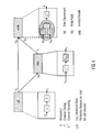
- Fig. 1 shows a block diagram of a receiver 100 for decoding a receive signal 102 in a wireless communication system according to an embodiment of the invention.
- the receiver 100 comprises a signal determiner 110, a soft information determiner 120 and a soft information decoder 130.
- the signal determiner 110 is connected to the soft information determiner 120 and the soft information determiner 120 is connected to the soft information decoder 130.
- the signal determiner 110 determines a complex receive value 112 for the receive signal 102 received from a relay station. Further, the soft information determiner 120 obtains a soft information 122 represented by a combination of a first probability value and a second probability value.
- the first probability value is derivable by adding a value depending on an overall probability density function for each symbol s of a modulation alphabet A comprising a same first bit value (0 or 1) at a same bit position of the symbols, wherein each symbol s of the modulation alphabet A represents at least two bits (e.g. 4 bits for 16-QAM).
- the overall probability density function indicates a probability of receiving the complex receive value 112, if a signal representing the respective symbol s considered for adding was transmitted from a transmitter to a relay station, wherein the signal representing the respective symbol causes the receive signal 102 received from the relay station.
- the second probability value is derivable by adding a value depending on the overall probability density function for each symbol s of the modulation alphabet A comprising a same second bit value (1 or 0) at the same bit position of the symbols.
- the first bit value and the second bit value are different.
- the soft information decoder 130 decodes payload data 132 contained by the receive signal 102 based on the obtained soft information 122.
- the receiver 100 By combining the first probability value and the second probability value, the receiver 100 considers a ratio of a bit of the payload data being a logical 0 or a logical 1. For this, symbols with the same first bit value at the same bit position of the symbols are considered for the first probability value and symbols with the same second bit value at the same bit position are considered for the second probability value. For both probability values the respective symbols are considered by evaluated the same overall probability density function. With this soft information 122 the payload data 132 can be decoded. In this way the behavior of a relay station, which forwards data, can be considered more accurate at the receiver 100 for advanced modulation schemes (e.g. 16-QAM). Therefore, the bit error rate may be reduced and/or the mutual information may be increased.
- advanced modulation schemes e.g. 16-QAM
- the receive signal 102 may be, for example, a radio signal received from the relay station or a signal obtained by downmixing and digitizing the radio signal received from the relay station.
- the complex receive value 112 may indicate a point in the complex plane comprising a real component and an imaginary component or may indicate an amplitude and phase of the receive signal 102 for the time interval used for transmitting a symbol. In an ideal system without disturbances or sources of errors, the complex receive value 112 may indicate exactly a symbol s of the modulation alphabet A. Due to disturbances like noise or interferences, the determined complex receive value 112 may represent a point somewhere between the symbols of the modulation alphabet A.
- Each symbol s of the modulation alphabet A represents at least two bits such as, for example, 16-QAM (quadrature amplitude modulation) with 4 bits per symbol or 64-QAM with 6 bits per symbol. Since there is more than one bit per symbol, the overall probability density function is considered for each symbol comprising the same bit value at an observed bit position.
- the soft information 122 obtained for the observed bit e.g. the first bit of a symbol or another specific bit of a symbol
- the soft information decoder 130 may decide whether the observed bit is a logical 0 or a logical 1.
- the symbols of the modulation alphabet may comprise more than two bits in preferred embodiments.
- each symbol comprising four bits and the last bit position is observed, then the same bit position of the symbols is the last bit of each symbol and the symbols comprising a 0 (or a 1) at the last bit position are considered for the first probability value and the symbols comprising a 1 (or a 0) at the last bit position are considered for the second probability value.
- Each bit of a symbol may correspond to a bit of the payload data 132, and therefore a soft information 122 may be calculated for each bit of a symbol.
- the first probability value and the second probability value are derivable by adding values depending on the overall probability density function.
- the receiver 100 receives the receive signal from the relay station, but it receives no signal (or a signal with insufficient signal quality) from transmitter directly.
- the first probability value and the second probability value may be derivable by adding values of the overall probability density function.
- the receiver 100 may receive the receive signal from the relay station and a receive signal from the transmitter directly.
- the first probability value and the second probability may be derivable by adding values of a product of the overall probability density function and a probability density function depending on the receive signal received from the transmitter.
- the overall probability density function takes into account a probability of receiving the determined complex receive value, if a specific symbol was transmitted by the transmitter to the relay station and after processing by the relay station transmitted to the receiver. In other words, the signal representing the respective symbol causes the receive signal 102.
- the overall probability density function considers the behavior of the relay station. For example, it takes into account whether the relay station uses an amplified forward method, a decode forward method, an estimate forward method or another relay method. This may be done, for example, by considering a relay function used by the relay station for relaying a signal received from the transmitter to the receiver by the overall probability density function.
- the overall probability density function depends on the specific symbol originally transmitted from the transmitter. Therefore, the overall probability density function is considered for each symbol comprising the first bit value at the observed bit position for the first probability value. Further, the overall probability density function is considered for each symbol comprising the second bit value at the observed bit position for the second probability value.
- the soft information decoder 130 may decode the payload data 132 contained by the receive signal in various ways, some of them are mentioned later on. One example may be to determine a soft information 122 for each bit of the payload data 132 and decide based on the respective soft information 122 whether a bit is a logical 1 or a logical 0. Further, a channel coding or interleaving of the receive signal 102 may be considered by the soft information decoder 130.
- the receiver 100 may be part of a user equipment as for example a mobile phone or laptop or part of a base station as for example an evolved node B (eNB).
- eNB evolved node B
- the soft information determiner 120 may determine the soft information by itself. For this, the soft information determiner 120 may calculate the first probability value by adding a value depending on the overall probability density function for each symbol s of the modulation alphabet A comprising the same first bit value at the same bit position of the symbols. Further, the soft information determiner 130 may calculate the second probability value by adding a value depending on the overall probability density function for each symbol s of the modulation alphabet A comprising the same second bit value at the same bit position of the symbols. Then, the soft information determiner 130 may combine the first probability value and the second probability value to obtain the soft information 122.
- the soft information determiner 120 may combine the first probability value and the second probability value by dividing the first probability value by the second probability value.
- the receiver 100 may comprise a storage unit configured to store a lookup table containing a plurality of soft information for a plurality of predefined complex receive values.
- Fig. 2 shows an example for such a receiver 200 according to an embodiment of the invention.
- the receiver 200 is similar to the receiver shown in Fig. 1 , but comprises additionally a storage unit 240 connected to the soft information determiner 120.
- the soft information determiner 120 may determine a soft information 122 for decoding based on the plurality of soft information contained by the lookup table depending on the determined complex receive value 112.
- a plurality of soft information may be predetermined and stored in a lookup table.
- the soft information determiner 120 may select one of the stored soft information (e.g. the soft information corresponding to the predefined complex receive value closest to the determined complex receive value) or may interpolate between soft information of two neighboring predefined complex receive values, if the determined complex receive value lies between the two neighboring predefined complex receive values (e.g. by linear interpolation).
- the lookup table may contain a plurality of soft information for one or more different modulation alphabets A.
- a receiver can be adapted to a specific application, so that the necessary storage space of the storage unit 240 can be reduced, or the receiver can be used more flexibly for several different modulation alphabets A.
- the hardware effort and/or the process time for decoding can be significantly reduced in comparison to a receiver calculating the soft information by itself.
- the soft information determiner 120 calculates the soft information by itself, the bit error rate may be further decreased and/or the mutual information may be further increased in comparison to a receiver using a lookup table, since the soft information may be calculated more accurately.
- the signal determiner 110, the soft information determiner 120, the soft information decoder 130 and the storage unit 240 may be, for example, independent hardware units or part of a digital signal processor, a microcontroller or a computer as well as a computer program or a software product for running on a digital signal processor, a microcontroller or a computer.
- the overall probability density function may be based on a relay function known by the receiver. This known relay function is used by the relay station to determine a radio signal to be transmitted to the receiver based on a radio signal received from the transmitter. In other words, the relaying from signals received from the transmitter to the receiver is based on the relay function.
- the relay station may consider a channel coding of a signal and may perform a soft output channel decoding, as for example shown in " P. Weitkemper, D. Wübben, and K.-D. Kammeyer. Minimum MSE Relaying for Arbitrary Signal Constellations in Coded Relay Networks. In IEEE Vehicular Technology Conference, Barcelona, Spain, April 2009 ".
- the relay can make use of the channel code, and as a consequence, the channel is not memoryless and the whole receive vector and the code constraint may be considered.
- the resulting estimated symbol s R is then normalized to the power constraint of the relay.
- the general definition of the expectation value given by the sum of all symbols weighted by the corresponding symbol probability is considered E s
- y SR , C ⁇ s s ⁇ p s
- y SR / y , C) denotes the extrinsic probability delivered by the channel decoder about s . It can be calculated as the product of the corresponding extrinsic code bit probabilities as these probabilities can be assumed to be independent of each other p s
- y SR / y , C ⁇ i Id M p d i s
- y SR / y , C ) denotes the extrinsic probability of the i-th bit of symbol s conditioned on the received vector and the code constraint.
- s) in equation (10d) is the probability based on the channel observation.
- y SR . or f y SR ⁇ E s
- y SR , C ⁇ ⁇ s ⁇ A s ⁇ p s
- y SR . or f y SR ⁇ AF ⁇ y SR
- the relay function may be based on a scaling factor (e.g. ⁇ or ⁇ AF ) and a relay probability density function (e.g. ⁇ s ⁇ A s ⁇ p s
- a scaling factor e.g. ⁇ or ⁇ AF
- a relay probability density function e.g. ⁇ s ⁇ A s ⁇ p s
- the receiver comprises a storage unit for storing a scaling factor of the relay function f(Y SR ) and to provide a scaling factor ⁇ to the soft information determiner 130 for determining the soft information.
- the soft information determiner 120 may determine a new scaling factor and update the stored scaling factor by the new scaling factor, if a noise information contained by the receive signal changes more than a predefined threshold.
- the noise information contained by the receive signal indicates a noise level of a channel between the transmitter and the relay station.
- the scaling factor used by the relay station for determining a signal to be transmitted to the receiver may depend on a noise level of the channel between the transmitter and the relay station.
- the receiver can update the scaling factor used for determining the soft information.
- the predefined threshold By choosing the predefined threshold, an accuracy of considering a variation of the scaling factor can be adapted. A large predefined threshold reduces the computational efforts, while a low predefined threshold may increase the accuracy.
- the storage unit for storing the scaling factor may be implemented in the same way as the storage unit for storing the lookup table shown in Fig. 2 .
- the soft information 122 represents the logarithm of the first probability value divided by the second probability value, so that the soft information 122 represents a logarithmic likelihood ratio. Since the first probability value indicates a probability of a bit being equal to the first bit value and the second probability value indicating a probability of the bit being equal to the second bit value, calculating the logarithm of the first probability value divided by the second probability value results in a logarithmic likelihood ratio (LLR).
- LLR logarithmic likelihood ratio
- the overall probability density function may depend on the noise levels of the channel from transmitter to the relay station and from the relay station to the receiver.
- An information about the noise level of the channel between the transmitter and the relay station may be transmitted from the relay station to the receiver, so that this information may be contained by the receive signal.
- the relay station may also transmit information about the noise level of the channel between the relay station and the receiver to the receiver.
- the receiver may measure or determine the noise level of the channel between the relay station and the receiver by itself.
- the signal determiner 110 may determine or extract a first noise information from the receive signal indicating a noise level of a channel between the relay station and the receiver.
- the signal determiner 110 may extract a second noise information contained by the receive signal 102 indicating a noise level of a channel between the transmitter and the relay station.
- the overall probability density function may depend on the first noise information and on the second noise information.
- the first noise information may be the variance ⁇ D 2 of the noise of the channel between the relay station and the receiver and the second noise information may be the variance ⁇ R 2 of the noise of the channel between the transmitter and the relay station.
- the lookup table may contain soft information for the plurality of predefined complex receive values and additionally for a plurality of predefined first noise information values and a plurality of predefined second noise information values.
- each soft information contained by the lookup table depends on a predefined complex receive value and additionally on a predefined first noise information value and a second noise information value.
- the soft information determiner 130 may determine the soft information for decoding depending on the determined complex receive value, the determined first noise information and the determined second noise information.
- a signal is also received directly from the transmitter. Therefore, the receive signal received from the transmitter may be considered additionally to the receive signal received from the relay station.
- the soft information determiner 120 may obtain the first probability value and the second probability value depend on a product of the overall probability density function and a probability density function depending on a receive signal received from the transmitter.
- the receive signal received from the transmitter may contain the same payload data 132 as the receive signal received from the relay station, a time alignment may be necessary, since it is likely that the two signals are received at different times.
- the inventive concept is described in more detail for an example using a maximum likelihood detection for a minimum mean square error relaying.
- the concept is described for a receiver receiving signals from the relay station and the transmitter, it can be seen that the concept also works for a receiver only receiving a signal from the relay station (or a plurality of relay stations).
- Maximum-Likelihood detection (decoding payload data based on the soft information) can be performed by calculating the Log-Likelihood Ratio (LLR) based on the pdfs of the received signal which can be combined with other pdfs or directly fed to a soft-input channel decoder (soft information decoder).
- LLR Log-Likelihood Ratio
- y RD , y SD p d 1
- L d ln ⁇ s ⁇ A ⁇ 0 p y SD
- the first part denoted as L SD
- L SRD is quite clear as this belongs to a Gaussian channel.
- the second part L SRD is not based on a Gaussian channel as the nonlinear relay function is involved and therefore requires the knowledge of a more complicated probability density function (pdf) that will be investigated in the following.
- equation (13) can be used, for example, when the modulation alphabet used by the transmitter differs from the modulation alphabet used by the relay station (e.g. different constellation of the same modulation alphabet or different modulation alphabets).
- equation (13) may be used, although the bits of a symbol used by the transmitter and the bits of the symbols used by the relay station are not independent from each other, since the errors caused by the simplification may be negligible or acceptable in comparison to the reduced computational effort.
- Equation (13) The probabilities in equation (13) are equal to p y RD
- d ⁇ s ⁇ A ⁇ d p y RD
- a v d represents the set of modulation symbols mapped to bit tuples with d ⁇ ⁇ 0, 1 ⁇ at the v-th position (symbols comprising the same bit value at the same bit position).
- Equation (18) is one example for an overall probability density function. More general, the overall probability density function may be based on a first probability density function p(y RD
- the first probability density function and the second probability density function may be normal distributions, for example.
- Fig. 6 shows an example for the first probability density function p(y RD
- the relay station may transmit the variance ⁇ R 2 (second noise information).
- the first probability density function indicates a probability, that a specific value y RD is received (by the receiver), if the relay station transmits ⁇ (y SR ).
- the receiver does not know the exact transmit value transmitted by the relay. Therefore, all possible values of ⁇ (y SR ) are observed, weighted with the probability for the occurrence of the value p(y SR
- An important aspect of the described concept may be that the whole calculation (of the soft information) is based on Gaussian distributions, and only the used modulation (modulation alphabet), the relay function and the noise variances of the two channels must be known (at the receiver), for example. Therefore, it may be possible to calculate the maximum likelihood exactly and efficiently.
- This equation can be evaluated very efficiently by mainly calculating two Gaussian densities and a numerical integration as shown in the following. Starting with a simple Gaussian distribution sufficiently sampled, all required values and densities can be obtained very simple. It should be noted, that the first four steps of the following implementation example have to be done only once per frame or even less, as the expressions do not depend on the actual received signal but only on the SNR (signal to noise ratio) of the first hop (transmission from the transmitter to the relay station). Only the later steps have to be executed per received value (for each bit of a symbol).
- Is calculated (e.g. representing a Gaussian distribution).
- p(y SR ) is calculated with the result for p(y SR
- p y SR ⁇ s ⁇ A p y SR
- y SR ⁇ is calculated with the results for p(y SR ) and p(y SR
- y SR ⁇ s ⁇ A s ⁇ p y SR
- the normalization factor ⁇ is determined with the results for p(y SR ) and E ⁇ s
- y SR ⁇ ⁇ 1 ⁇ - ⁇ ⁇ ⁇ E s
- s) for each s ⁇ A is calculated with the results above.
- s ⁇ - ⁇ ⁇ 1 2 ⁇ ⁇ ⁇ ⁇ D 2 ⁇ exp - y RD - f y SR 2 2 ⁇ ⁇ D 2 ⁇ p y SR
- LLR ln ⁇ s ⁇ A ⁇ 0 p y RD
- All densities may be known as long as the Signal-to-Noise Ratios (SNR) of both hops are known at the receiver, for example. This information may be required anyway also for AF and DetF and has either to be estimated or to be signaled to the destination.
- SNR Signal-to-Noise Ratios
- This information may be required anyway also for AF and DetF and has either to be estimated or to be signaled to the destination.
- c ) for the signal from the relay can be combined with those for the direct link to calculate the LLRs or in the case of independence by just summing up the different LLRs. The resulting output can directly be fed into the channel decoder.
- a ML detector may be used also for the DetF relaying function.
- DetF often a suboptimal detector based on an equivalent Gaussian channel is used especially for higher order modulation schemes.
- the proposed ML detector for DetF is easy to implement due to the simple relay function.
- LLR Log-Likelihood Ratio
- ⁇ ) describes the second hop, meaning the probability of receiving y RD , conditioned on ⁇ being transmitted by the relay. This simply corresponds to a Gaussian distribution with mean ⁇ .
- s ⁇ 1 ⁇ ⁇ ⁇ D 2 ⁇ exp - y RD - s ⁇ 2 ⁇ D 2
- This conditioned pdf is weighted with the probability p ( ⁇
- the probability p ( ⁇ l s) describes the transition probability of the equivalent channel between source and the relay's output, meaning that the relay transmitted ⁇ conditioned on the source transmit symbol being s , corresponding to the symbol error probability.
- the soft information represents an approximated combination of the first probability value and the second probability value. This may be done by a fitting algorithm or by a piecewise linear approximation, for example.
- the soft information represents a logarithmic likelihood ratio
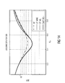
- Fig. 8 An example for a piecewise linear approximation is shown in Fig. 8 . It shows an example for a signal to noise ratio of the channel between the transmitter and the relay station of 17 dB and a signal to noise ratio of the channel between the relay station and the receiver of 3 dB.
- the logarithmic likelihood ratio values are illustrated for the second bit (of a symbol) of the 16-QAM.
- the true logarithmic likelihood ratio (LLR) is approximated piecewise by three lines in the observed range of the real component of the complex receive value Re(y RD ).
- Fig. 9 A further example is shown in Fig. 9 .
- the signal to noise ratio of the channel between the transmitter and the relay station as well as the signal to noise ratio of the channel between the relay station and the receiver is equal to 10 dB and the logarithmic likelihood ratio values of the first bit (of a symbol) of a 16-QAM are illustrated.
- the true logarithmic likelihood ratio is approximated by four lines in the observed region.
- the necessary storage space of the storage unit of a receiver implementation using a lookup table for the soft information can be reduced, since storing two different soft information for each approximation line (e.g. the intersection points of the approximation lines) may be sufficient.
- FIG. 10 a system with a geographical model is used, where the relay is on the direct line between source and destination. It shows a diagram indicating an uncoded bit error rate at the receiver for 16-QAM after maximum likelihood or maximum ratio combining versus the distance between source (transmitter) and relay.
- Bit error rates are shown for amplify forward (AF), estimate forward with maximum ratio combining (EF MRC), estimate forward with maximum likelihood (EF ML), detect forward with maximum ratio combining (DetF MRC) and detect forward with maximum likelihood (DetF ML). All results here are for AWGN channels without fading and the path loss exponent is equal to 2. In this figure the uncoded bit error rate (BER) is shown versus the location of the relay. In addition the results for a linear combining approach are shown. For EF an effective channel is assumed as done in " P. Weitkemper, D. Wübben, and K.-D.
- AF shows bad performance when the relay is in the middle whereas DetF and EF show good results.
- the most interesting case is when the relay is near the destination.
- AF becomes better than DetF as is well known and has been often observed.
- EF with ML-detection outperforms DetF clearly and is nearly as good as AF.
- EF is suitable for all locations of the relay.
- MI mutual information
- the diagram shows the mutual information for estimate forward (EF), detect forward (DetF) and amplify forward (AF), all with ML-detection.
- EF estimate forward
- DetF detect forward
- AF amplify forward
- the x-axis indicates the signal to noise ratio between the relay station (RN, relay node) and the transmitter (eNB, evolved node B) and the different shown characteristics are related to different signal to noise ratios between the receiver (UE, user equipment) and the relay station RN.
- the mutual information MI determines the maximum possible transmission rate. Higher mutual information enables higher throughput.
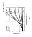
- Fig. 12 shows the mutual information at the receiver before channel decoding.
- the SNR on the direct connection is fixed to 5 dB, but similar results are obtained for different values.
- the same conclusions can be drawn as before.
- the MI with AF is considerably less than for EF
- DetF shows significant loss for medium SNR on the first hop but large SNR on the second hop.
- the diagram indicates the uncoded bit error rate (BER) for amplify forward (AF), estimate forward with maximum ratio combining (EF MRC), estimate forward with maximum likelihood (EF ML) and detect forward with maximum likelihood (DetF ML).
- the BER is shown for 2, 4 and 8 relays transmitting on orthogonal resources now assuming a path loss exponent of 3.
- FIG. 14 shows a diagram indicating a bit error rate (BER) without convolution code (uncoded) for 16-QAM versus distance between source (transmitter) and relay.
- Fig. 15 shows a bit error rate with convolution code for 16-QAM versus distance between source and relay.
- the illustration of the respective lines is equal to the illustration in Fig. 14 .
- Fig. 14 the BER of the code bits without channel decoding at the destination is shown
- Fig. 15 shows the BER of the info bits after decoding the applied [5 7] 8 convolutional code.
- the gain of the ML-detector for EF gets larger with channel coding.
- one specific L-value not only influences the decision on the corresponding code bit but due to the correlation introduced by the code it influences many information bits. This leads to a stronger impact of the correctness of each L-value, which is only ensured by the ML-detection.
- Some embodiments according to the invention relate to a wireless communication system comprising a receiver according to the inventive concept. Further, the wireless communication system comprises a relay station, wherein a relay function used by the relay station is considered by the receiver in terms of the overall probability density function, which is based on a relay function. An example for such a wireless communication system is shown in Fig. 4 .
- a user equipment performs a channel coding C and a modulation A for transmitting data d.
- the resulting signal x s sent to a relay station and optionally (if the eNB is in receive distance) to an evolved node B (eNB).
- the relay station or relay node performs an optional channel decoding and applies the relay function ⁇ (y SR ) to the receive signal to obtain a signal to be transmitted to the evolved node B.
- the evolved node B calculates a logarithmic likelihood ratio (or determines a logarithmic likelihood ratio from a lookup table) for the signal received from the relay station and optionally for a signal received from the user equipment. With this information a channel decoding C -1 is performed to obtain the payload data d.
- the configuration shown in Fig. 4 indicates a classical three terminal system with one source, one destination and one relay. The direct path may also be received by the destination, for example, separated by time division duplex (TDD) or frequency division duplex (FDD). A channel decoding may not be required at the relay station, so that a simple (cheap) relay can be realized.
- relay protocols as for example, amplify forward (AF), detect forward (DETF) and estimate forward (EF) may be used. Out of them, estimate forward may be an optimal function as it minimizes the means squared error at the receiver.
- AF amplify forward
- DETF detect forward
- EF estimate forward
- estimate forward may be an optimal function as it minimizes the means squared error at the receiver.
- the described concept may also be considered for standardization, for example, for beyond Rel. 10.
- Fig. 4 also shows an example for a structure of a maximum likelihood (ML) receiver at the destination (evolved node B in this example).
- ML maximum likelihood
- both received signals contain useful information, so that the signals should be combined properly.
- the summation of LLRs is optimal, if the observations about the information bits d are independent. In the case of dependent observations the overall pdf and a pdf depending on the receive signal from the transmitter may be combined before calculating the LLR, although alternatively the summation of LLRs may be used as an approximation to reduce the computational effort.
- the inventive concept may provide an optimal solution for estimate forward with higher order modulation schemes as for example used in LTE (long-term evolution).
- the present invention provides, for example, a simple but closed form receiver functionality that enables maximum likelihood performance for a system with relays applying estimate forward with higher order modulation schemes. Additionally, if a soft input channel decoder (soft information decoder) is used at the receiver, exact logarithmic likelihood ratios can be computed. In this way, the possible gain of estimate forward may be preserved even for arbitrary modulation schemes.
- the proposed receiver may calculate an exact probability density function.
- the exact probability density function may be required to enable a maximum likelihood receiver.
- a receiver using the present invention may be the best in all shown cases.
- a lower bit error rate may be achievable as well as a higher user throughput and/or better user performance. Therefore, a receiver according to the described concept may also be a good candidate for beyond LTE Rel. 10.
- the relay station may be implemented in various ways. The implementation depends on mainly on the relay function.
- Fig. 5 shows a diagram comparing relay functions f(y SR ) for amplify forward AF, detect forward DETF and estimate forward EF. Amplify forward just normalizes received signals and is a linear function. Detect forward makes a hard decision, so that some information is lost. Estimate forward combines both and is nearly linear at low reliability, and nearly hard decision at high reliability.
- Some embodiments according to the invention relate to a maximum likelihood receiver for minimum means squared error relaying.
- a Maximum Likelihood (ML) receiver for Estimate-Forward relaying that minimizes the Mean Squared Error was described for arbitrary modulation alphabets. This enables ML performance even in the case of more than one signal path received at the destination.
- known solutions use a Gaussian approximation leading to significant loss in terms of coded and uncoded Bit Error Rate as well as Mutual Information.
- a simple algorithm to calculate the required Log-Likelihood Ratios is presented showing the efficient realization of the general ML condition for the applied Estimate-Forward. The presented concept is applicable for wireless communication systems using simple and cheap relays with small delay without complex decoding or encoding. With the presented receiver EF shows significant performance gains in comparison to AF and DetF and is therefore a very promising approach for future mobile communication systems.
- Fig. 16 shows a flowchart of a method 1600 for decoding a receive signal in a wireless communication system according to an embodiment of the invention.
- the method 1600 comprises determining 1610 a complex receive value for the receive signal, obtaining 1620 a soft information and decoding 1630 payload data contained by the receive signal based on the obtained soft information.
- the soft information represents a combination of a first probability value and a second probability value.
- the first probability value is derivable by adding a value depending on an overall probability density function for each symbol of a modulation alphabet comprising a same first bit value at a same bit position of the symbols, wherein each symbol of the modulation alphabet represents at least two bits.
- the overall probability density function indicates a probability of receiving the complex receive value, if a signal representing the respective symbol considered for adding was transmitted from a transmitter to a relay station, wherein the signal representing the respective symbol causing the receive signal received from the relay station.
- the second probability value is derivable by adding a value depending on the overall probability density function for each symbol of the modulation alphabet comprising a same second bit value at the same bit position of the symbols. The first bit value and the second bit value are different.
- the method 1600 may comprise additional, optional steps representing additional features of the inventive concept described above.
- Some embodiments according to the invention relate to a method combining signals from a source and at least one relay node for a system where the source transmits arbitrary higher order modulation schemes (e.g. 16-QAM) and at least one node is a relay node applying a mean squared error minimizing function called estimate forward and where the exact probability density function is used in order to apply a maximum likelihood receiver.
- the signals may be received from two or more relay nodes where at least one applies estimate forward.
- at least one relay decodes the received message with a soft output decoder and calculates the mean squared error minimizing function jointly based on channel observation and channel decoder output. Further, a piecewise linear approximation of the maximum likelihood receiver may be applied.
- aspects of the described concept have been described in the context of an apparatus, it is clear that these aspects also represent a description of the corresponding method, where a block or device corresponds to a method step or a feature of a method step. Analogously, aspects described in the context of a method step also represent a description of a corresponding block or item or feature of a corresponding apparatus.
- embodiments of the invention can be implemented in hardware or in software.
- the implementation can be performed using a digital storage medium, for example a floppy disk, a DVD, a Blue-Ray, a CD, a ROM, a PROM, an EPROM, an EEPROM or a FLASH memory, having electronically readable control signals stored thereon, which cooperate (or are capable of cooperating) with a programmable computer system such that the respective method is performed. Therefore, the digital storage medium may be computer readable.
- Some embodiments according to the invention comprise a data carrier having electronically readable control signals, which are capable of cooperating with a programmable computer system, such that one of the methods described herein is performed.
- embodiments of the present invention can be implemented as a computer program product with a program code, the program code being operative for performing one of the methods when the computer program product runs on a computer.
- the program code may for example be stored on a machine readable carrier.
- inventions comprise the computer program for performing one of the methods described herein, stored on a machine readable carrier.
- an embodiment of the inventive method is, therefore, a computer program having a program code for performing one of the methods described herein, when the computer program runs on a computer.
- a further embodiment of the inventive methods is, therefore, a data carrier (or a digital storage medium, or a computer-readable medium) comprising, recorded thereon, the computer program for performing one of the methods described herein.
- a further embodiment of the inventive method is, therefore, a data stream or a sequence of signals representing the computer program for performing one of the methods described herein.
- the data stream or the sequence of signals may for example be configured to be transferred via a data communication connection, for example via the Internet.
- a further embodiment comprises a processing means, for example a computer, or a programmable logic device, configured to or adapted to perform one of the methods described herein.
- a processing means for example a computer, or a programmable logic device, configured to or adapted to perform one of the methods described herein.
- a further embodiment comprises a computer having installed thereon the computer program for performing one of the methods described herein.
- a programmable logic device for example a field programmable gate array
- a field programmable gate array may cooperate with a microprocessor in order to perform one of the methods described herein.
- the methods are preferably performed by any hardware apparatus.
Abstract
The receiver comprises a signal determiner, a soft information determiner and a soft information decoder. The signal determiner determines a complex receive value for the receive signal received from a relay station. Further, the soft information determiner obtains a soft information represented by a combination of a first probability value and a second probability value. The first probability value is derivable by adding a value depending on an overall probability density function for each symbol of a modulation alphabet comprising a same first bit value at a same bit position of the symbols, wherein each symbol of the modulation alphabet represents at least two bits. Further, the overall probability density function indicates a probability of receiving the complex receive value, if a signal representing the respective symbol s considered for adding was transmitted from a transmitter to a relay station, wherein the signal representing the respective symbol causes the receive signal received from the relay station. The second probability value is derivable by adding a value depending on the overall probability density function for each symbol of the modulation alphabet comprising a same second bit value at the same bit position of the symbols. Further, the soft information decoder decodes payload data contained by the receive signal based on the obtained soft information.
Description
- Embodiments according to the invention relate to wireless communication systems and particularly to a receiver and a method for decoding a receive signal in a wireless communication system.
- One major goal for future wireless communication systems is a uniform user experience. In cellular systems cell-edge users suffer from path loss and interference from neighboring cells and experience a much lower data rate than users in the cell centre. In order to combat this problem, additional relay nodes can be used to support the communication. Up to now mainly two relaying functions are considered, namely Amplify-Forward (AF) and Decode-Forward (DF). DF can either mean a channel decoding at the relay or a hard decision directly on the received signal which will be called DetF here to avoid confusion. The latter case is interesting as the avoidance of computationally complex channel decoding would enable very simple and small relays with low power consumption. But both, AF and DetF have certain drawbacks leading to the idea to find more sophisticated solutions. AF suffers from noise amplification whereas with DetF useful information is lost due to the hard decision. For this purpose a relay function minimizing the mean squared error called Estimate-Forward (EF) has been proposed in the literature combining the benefits of AF and DF. The function for EF is the expectation value of the transmitted symbol and therefore combines the idea of exploiting the discrete alphabet with the aim of preserving reliability information about the first hop. In any case, it is desired to increase the user throughput.
- It is the object of the present invention to provide an improved concept for decoding a receive signal in a wireless communication system, which allows to decrease the bit error rate and/or to increase the mutual information.
- This object is solved by a receiver according to
claim 1 or a method according to \claim 14. - An embodiment of the invention provides a receiver for decoding a receive signal in a wireless communication system comprising a signal determiner, a soft information determiner and a soft information decoder. The signal determiner is configured to determine a complex receive value for the receive signal. Further, the soft information determiner is configured to obtain a soft information represented by a combination of a first probability value and a second probability value. The first probability value is derivable by adding a value depending on an overall probability density function for each symbol of a modulation alphabet comprising a same first bit value at a same bit position of the symbols, wherein each symbol of the modulation alphabet represents at least two bits. The overall probability density function indicates a probability of receiving the complex receive value, if a signal representing the respective symbol considered for adding was transmitted from a transmitter to a relay station, the signal representing the respective symbol causing the receive signal received from the relay station. The second probability value is derivable by adding a value depending on the overall probability density function for each symbol of the modulation alphabet comprising a same second bit value at the same bit position of the symbols. The first bit value and the second bit value are different. Further, the soft information decoder is configured to decode payload data contained by the receive signal based on the obtained soft information.
- Embodiments according to the present invention are based on the central idea that payload data contained by a receive signal can be decoded based on a soft information indicating a probability whether a bit to be decoded is a logical 0 or a logical 1 for a wireless communication system using a modulation alphabet with at least four different symbols (each symbol represents at least two bits), if the data is sent via a relay station. For this, the behavior of the relay station is considered by the soft information, since the soft information depends on an overall probability density function indicating a probability of receiving the complex receive value, if a signal representing the respective symbol considered for adding was transmitted to the relay station, wherein the signal representing the respective symbol causes the receive signal received from the relay station. In this way, the behavior of the relay station can be considered for complex modulation alphabets more accurate. Therefore, the bit error rate may be reduced and/or the throughput or the mutual information may be increased.
- In some embodiments according to the invention, the soft information determiner calculates the first probability value and the second probability value and combines the first and the second probability value to obtain the soft information. In this way, the soft information determiner calculates the soft information in dependence on the determined complex receive value.
- Some other embodiments of the invention comprise a storage unit configured to store a lookup table containing a plurality of soft information for a plurality of predefined complex receive values. Further, the soft information determiner determines the soft information for decoding based on the plurality of soft information contained by the lookup table depending on the determined complex receive value. In this case, a plurality of soft information is predetermined for the plurality of predefined complex receive values and the soft information determiner may select one of them or may interpolate between soft information contained by the lookup table to obtain the soft information used by the soft information decoder for decoding.
- In some embodiments according to the invention, the soft information represents a logarithmic likelihood ratio.
- Some embodiments according to the invention relate to an overall probability density function depending on a relay function known by the receiver. The relay function is used by the relay station to determine a radio signal to be transmitted to the receiver based on a radio signal received from the transmitter. The relay function may be based on a minimum mean square error approach.
- Embodiments according to the invention will be detailed subsequently referring to the appended drawings, in which:
- Fig. 1
- is a block diagram of a receiver;
- Fig. 2
- is a block diagram of a receiver;
- Fig. 3
- is a schematic illustration of a system model of a classical three-terminal system;
- Fig. 4
- shows a schematic illustration of a target configuration for uplink;
- Fig. 5
- is a schematic illustration of relay functions;
- Fig. 6
- is a schematic illustration of a probability density function;
- Fig. 7
- is a schematic illustration of a comparison of probability density functions;
- Fig. 8
- is a schematic illustration of a piecewise linear approximation of a logarithmic likelihood ratio;
- Fig. 9
- is another schematic illustration of a piecewise linear approximation of a logarithmic likelihood ratio;
- Fig. 10
- is a diagram indicating an uncoded bit error rate at the receiver for 16-QAM after maximum likelihood or maximum ratio combining versus a distance between source and relay;
- Fig. 11
- is a diagram indicating the mutual information at the receiver for 16-QAM after maximum likelihood combining for different values of SNRSR and SNRRD;
- Fig. 12
- is a diagram indicating the mutual information at the receiver;
- Fig. 13
- is a diagram indicating an uncoded bit error rate for a different number of parallel relays for 16-QAM versus distance between source and relay;
- Fig. 14
- is a diagram indicating an error rate without convolution code for 16-QAM versus distance between source and relay;
- Fig. 15
- is a diagram indicating an error rate with convolution code for 16-QAM versus distance between source and relay; and
- Fig. 16
- is a flowchart of a method for decoding a receive signal in a wireless communication system.
- In the following, the same reference numerals are partly used for objects and functional units having the same or similar functional properties and the description thereof with regard to a figure shall apply also to other figures in order to reduce redundancy in the description of the embodiments.
- Forwarding reliability information in relay networks has attracted much attention in the last years as it combines the advantages of simple linear relaying like Amplify-Forward (AF) and hard decision relaying as Decode-Forward (DF) or Detect-Forward (DetF). In the following, uncoded transmission or coded transmission with a simple relay which does no channel decoding is considered. The latter case is interesting as channel coding is done in nearly all communication systems but in some cases the relay should be kept as simple as possible. Especially mobile relays with battery constraints are a promising approach for future communication systems. Although DetF shows good performance if the source-relay channel is good and AF is reasonable in the other case, both show significant loss in some cases. One possibility is to switch between relay functions depending on the specific scenario or channel conditions. The approach presented combines the advantages of AF and DetF by taking the discrete symbols into account like DetF but still preserving reliability information to be exploited at the receiver as AF, for example. Forwarding Log-Likelihood Ratios (LLR) in the case of BPSK (binary phase shift keying) or QPSK (quadrature phase shift keying), is shown, for example, in "X. Bao and J. Li, "Efficient Message Relaying for Wireless User Cooperation: Decode-Amplify-Forward (DAF) and Hybrid DAF and Coded-Cooperation," IEEE Transaction on Wireless Communications, vol. 6, no. 11, pp. 3975-3984, Nov. 2007" and "S. Yang and R. Kötter, "Network Coding over a Noisy Relay : a Belief Propagation Approach," in IEEE International Symposium on Information Theory, Nice, France, Jun. 2007" or modulating the phase of BPSK symbols according to the reliability, in "W. Pu, C. Luo, S. Li, and C. W. Chen, "Continuous Network Coding in Wireless Relay Networks," in IEEE Conference on Computer Communications, Apr. 2008, pp. 1526-1534". A more systematic approach is to look for an optimal relay function in a certain sense. For an uncoded system the Bit Error Rate (BER) could be an appropriate measure for a metric to be optimized. The resulting BER minimizing function for BPSK was derived in "1. Abou-Faycal and M. Medard, "Optimal uncoded regeneration for binary antipodal signaling," in IEEE International Conference on Communications, Paris, France, Jun. 2004" and extended to two-way relaying in "T. Cui, T. Ho, and J. Kliewer, "Memoryless relay strategies for two-way relay channels," IEEE Transactions on Communications, vol. 57, no. 10, pp. 3132-3143, 2009". Although this approach works well in uncoded two-hop systems, almost all communication systems are channel coded. In this case the uncoded BER is no meaningful measure but instead a relay function minimizing the mean squared error (MSE) was derived in "K. Gomadam and S. A. Jafar, "Optimal Relay Functionality for SNR Maximization in Memoryless Relay Networks," IEEE Journal on Selected Areas in Communications, vol. 25, no. 2, pp. 390-401, Feb. 2007". This function leads to the expectation value of the transmitted symbols also called soft symbols. This approach works for all modulation alphabets and was shown in ""On the Capacity of Memoryless Relay Networks," in IEEE International Conference on Communications, Istanbul, Turkey, Jun. 2006" to even maximize capacity at least for BPSK under the constraint of memoryless functions, meaning a symbolwise processing without e.g. channel decoding at the relay.
- This MSE minimizing function for memoryless relays called Estimate-Forward (EF) is a powerful approach for uncoded two-hop relaying systems. But if the aim of the relay is not only range extension but diversity and capacity gain, also the direct link between source and destination or even signals from other relays can be taken into account. In the practically interesting case of orthogonal medium access of source and relay, the two signals can be combined properly. Although the distribution needed for calculation of LLRs for the case of BPSK is known "R. Thobaben and E. G. Larsson, "Sensor-network aided cognitive radio: On the optimal receiver for estimate-and-forward protocols applied to the relay channel," in Asilomar Conference on Signals, Systems and Computers, Pacific Grove, USA, Nov. 2007" and "P. Weitkemper, D. Wübben, V. Kühn, and K.-D. Kammeyer, "Soft Information Relaying for Wireless Networks with Error-Prone Source-Relay Link," in 7th International ITG Conference on Source and Channel Coding, Jan. 2008", a general solution for arbitrary signal alphabets is still missing. A suboptimal solution often used is a Gaussian approximation of the signal transmitted by the relay leading to a simple weighted combining of these two received signals. This approach is not optimal due to the non-linearity function of the EF function. In the following, for example, a Maximum-Likelihood detection for EF is derived in a general manner enabling optimal reception by proper combining of the pdfs (probability density functions) to calculate LLR. The gain of EF and especially of the proposed receiver in such a system will be shown via simulations. This scheme can directly be applied to a coded system using a simple, non-decoding relay.
- In a considered
system 300 as shown, for example, inFigure 3 , information bits d are possibly channel encoded and interleaved, then mapped to modulation symbols s ∈ A and transmitted with transmit power PS. As the presented scheme can be applied to uplink and downlink, the terminal that wants to transmit a message is called source and can either be a UE (user equipment) or an eNB (evolved node B), and the terminal who wants to receive the message is called destination. The signal transmitted by the source S is


- The noise at the relay R and the destination D has
variance 


- If Amplify-Forward is applied, the function ƒ equals


- In the case of DetF simply a hard decision on the transmitted symbol is applied

- As mentioned before, both approaches are suboptimal and therefore a function minimizing the MSE may be considered. The Mean Squared Error (MSE) for an arbitrary relay function and discrete modulation alphabet A containing the symbols s yields (see for example "K. Gomadam and S. A. Jafar, "Optimal Relay Functionality for SNR Maximization in Memoryless Relay Networks," IEEE Journal on Selected Areas in Communications, vol. 25, no. 2, pp. 390-401, Feb. 2007")


- Normalization of equation (10) to the power constraint does not change the MSE minimizing property. The result is very general and valid for arbitrary modulation schemes as BPSK, QPSK, and M-QAM (multi-level quadrature amplitude modulation). In "K. Gomadam and S. A. Jafar, "Optimal Relay Functionality for SNR Maximization in Memoryless Relay Networks," IEEE Journal on Selected Areas in Communications, vol. 25, no. 2, pp. 390-401, Feb. 2007", for more than one relay either a multihop network is formed or several relays transmit simultaneously.
- In the following, orthogonal medium access via FDD or TDD is assumed between source (transmitter) and relays as this is an important case for practical systems. Although it is desired that a radio signal transmitted by the relay station is independent from a radio signal transmitted from the transmitter (e.g. frequency domain division FDD or time domain division TDD), also signals not independent from each other can be processed by using the proposed concept.
- Further, a receiver concept is described, which is able to deal with a large variety of relay functions used by a relay station for advanced modulation alphabets.
-
Fig. 1 shows a block diagram of areceiver 100 for decoding a receivesignal 102 in a wireless communication system according to an embodiment of the invention. Thereceiver 100 comprises asignal determiner 110, asoft information determiner 120 and asoft information decoder 130. Thesignal determiner 110 is connected to thesoft information determiner 120 and thesoft information determiner 120 is connected to thesoft information decoder 130. Thesignal determiner 110 determines a complex receivevalue 112 for the receivesignal 102 received from a relay station. Further, thesoft information determiner 120 obtains asoft information 122 represented by a combination of a first probability value and a second probability value. The first probability value is derivable by adding a value depending on an overall probability density function for each symbol s of a modulation alphabet A comprising a same first bit value (0 or 1) at a same bit position of the symbols, wherein each symbol s of the modulation alphabet A represents at least two bits (e.g. 4 bits for 16-QAM). Further, the overall probability density function indicates a probability of receiving the complex receivevalue 112, if a signal representing the respective symbol s considered for adding was transmitted from a transmitter to a relay station, wherein the signal representing the respective symbol causes the receivesignal 102 received from the relay station. The second probability value is derivable by adding a value depending on the overall probability density function for each symbol s of the modulation alphabet A comprising a same second bit value (1 or 0) at the same bit position of the symbols. The first bit value and the second bit value are different. Further, thesoft information decoder 130 decodespayload data 132 contained by the receivesignal 102 based on the obtainedsoft information 122. - By combining the first probability value and the second probability value, the
receiver 100 considers a ratio of a bit of the payload data being a logical 0 or a logical 1. For this, symbols with the same first bit value at the same bit position of the symbols are considered for the first probability value and symbols with the same second bit value at the same bit position are considered for the second probability value. For both probability values the respective symbols are considered by evaluated the same overall probability density function. With thissoft information 122 thepayload data 132 can be decoded. In this way the behavior of a relay station, which forwards data, can be considered more accurate at thereceiver 100 for advanced modulation schemes (e.g. 16-QAM). Therefore, the bit error rate may be reduced and/or the mutual information may be increased. - The receive
signal 102 may be, for example, a radio signal received from the relay station or a signal obtained by downmixing and digitizing the radio signal received from the relay station. The complex receivevalue 112 may indicate a point in the complex plane comprising a real component and an imaginary component or may indicate an amplitude and phase of the receivesignal 102 for the time interval used for transmitting a symbol. In an ideal system without disturbances or sources of errors, the complex receivevalue 112 may indicate exactly a symbol s of the modulation alphabet A. Due to disturbances like noise or interferences, the determined complex receivevalue 112 may represent a point somewhere between the symbols of the modulation alphabet A. - Each symbol s of the modulation alphabet A represents at least two bits such as, for example, 16-QAM (quadrature amplitude modulation) with 4 bits per symbol or 64-QAM with 6 bits per symbol. Since there is more than one bit per symbol, the overall probability density function is considered for each symbol comprising the same bit value at an observed bit position. With the
soft information 122 obtained for the observed bit (e.g. the first bit of a symbol or another specific bit of a symbol), thesoft information decoder 130 may decide whether the observed bit is a logical 0 or a logical 1. Although the described concept may be used already for symbols representing two bits, the symbols of the modulation alphabet may comprise more than two bits in preferred embodiments. - For example, if each symbol comprising four bits and the last bit position is observed, then the same bit position of the symbols is the last bit of each symbol and the symbols comprising a 0 (or a 1) at the last bit position are considered for the first probability value and the symbols comprising a 1 (or a 0) at the last bit position are considered for the second probability value. Each bit of a symbol may correspond to a bit of the
payload data 132, and therefore asoft information 122 may be calculated for each bit of a symbol. - The first probability value and the second probability value are derivable by adding values depending on the overall probability density function. For example, the
receiver 100 receives the receive signal from the relay station, but it receives no signal (or a signal with insufficient signal quality) from transmitter directly. In this case, the first probability value and the second probability value may be derivable by adding values of the overall probability density function. Alternatively, thereceiver 100 may receive the receive signal from the relay station and a receive signal from the transmitter directly. In this case, the first probability value and the second probability may be derivable by adding values of a product of the overall probability density function and a probability density function depending on the receive signal received from the transmitter. - The overall probability density function takes into account a probability of receiving the determined complex receive value, if a specific symbol was transmitted by the transmitter to the relay station and after processing by the relay station transmitted to the receiver. In other words, the signal representing the respective symbol causes the receive
signal 102. In this way, the overall probability density function considers the behavior of the relay station. For example, it takes into account whether the relay station uses an amplified forward method, a decode forward method, an estimate forward method or another relay method. This may be done, for example, by considering a relay function used by the relay station for relaying a signal received from the transmitter to the receiver by the overall probability density function. - The overall probability density function depends on the specific symbol originally transmitted from the transmitter. Therefore, the overall probability density function is considered for each symbol comprising the first bit value at the observed bit position for the first probability value. Further, the overall probability density function is considered for each symbol comprising the second bit value at the observed bit position for the second probability value.
- The
soft information decoder 130 may decode thepayload data 132 contained by the receive signal in various ways, some of them are mentioned later on. One example may be to determine asoft information 122 for each bit of thepayload data 132 and decide based on the respectivesoft information 122 whether a bit is a logical 1 or a logical 0. Further, a channel coding or interleaving of the receivesignal 102 may be considered by thesoft information decoder 130. - The
receiver 100 may be part of a user equipment as for example a mobile phone or laptop or part of a base station as for example an evolved node B (eNB). - In some embodiments of the invention, the
soft information determiner 120 may determine the soft information by itself. For this, thesoft information determiner 120 may calculate the first probability value by adding a value depending on the overall probability density function for each symbol s of the modulation alphabet A comprising the same first bit value at the same bit position of the symbols. Further, thesoft information determiner 130 may calculate the second probability value by adding a value depending on the overall probability density function for each symbol s of the modulation alphabet A comprising the same second bit value at the same bit position of the symbols. Then, thesoft information determiner 130 may combine the first probability value and the second probability value to obtain thesoft information 122. - For example, the
soft information determiner 120 may combine the first probability value and the second probability value by dividing the first probability value by the second probability value. - In some other embodiments, the
receiver 100 may comprise a storage unit configured to store a lookup table containing a plurality of soft information for a plurality of predefined complex receive values.Fig. 2 shows an example for such areceiver 200 according to an embodiment of the invention. Thereceiver 200 is similar to the receiver shown inFig. 1 , but comprises additionally astorage unit 240 connected to thesoft information determiner 120. In this example, thesoft information determiner 120 may determine asoft information 122 for decoding based on the plurality of soft information contained by the lookup table depending on the determined complex receivevalue 112. In other words, instead of calculating the soft information for each bit of the receive signal, a plurality of soft information may be predetermined and stored in a lookup table. For example, thesoft information determiner 120 may select one of the stored soft information (e.g. the soft information corresponding to the predefined complex receive value closest to the determined complex receive value) or may interpolate between soft information of two neighboring predefined complex receive values, if the determined complex receive value lies between the two neighboring predefined complex receive values (e.g. by linear interpolation). - The lookup table may contain a plurality of soft information for one or more different modulation alphabets A. In this way, a receiver can be adapted to a specific application, so that the necessary storage space of the
storage unit 240 can be reduced, or the receiver can be used more flexibly for several different modulation alphabets A. - By using a lookup table containing a predetermined plurality of soft information, the hardware effort and/or the process time for decoding can be significantly reduced in comparison to a receiver calculating the soft information by itself. On the other hand, if the
soft information determiner 120 calculates the soft information by itself, the bit error rate may be further decreased and/or the mutual information may be further increased in comparison to a receiver using a lookup table, since the soft information may be calculated more accurately. - The
signal determiner 110, thesoft information determiner 120, thesoft information decoder 130 and thestorage unit 240 may be, for example, independent hardware units or part of a digital signal processor, a microcontroller or a computer as well as a computer program or a software product for running on a digital signal processor, a microcontroller or a computer. - In some embodiments according to the invention, the overall probability density function may be based on a relay function known by the receiver. This known relay function is used by the relay station to determine a radio signal to be transmitted to the receiver based on a radio signal received from the transmitter. In other words, the relaying from signals received from the transmitter to the receiver is based on the relay function.
- Some possible relay functions are already mentioned above (for amplify forward, detect forward and minimum mean square error relaying without channel coding). Further, the relay station may consider a channel coding of a signal and may perform a soft output channel decoding, as for example shown in "P. Weitkemper, D. Wübben, and K.-D. Kammeyer. Minimum MSE Relaying for Arbitrary Signal Constellations in Coded Relay Networks. In IEEE Vehicular Technology Conference, Barcelona, Spain, April 2009".
- For memoryless channels as uncoded AWGN (additive white Gaussian noise), one element


- The conditional expectation of the transmitted bits minimizes the MSUE (mean squared error) at the destination.

- The resulting estimated symbol


- Symbol probabilities based on the product of APP (a posteriori) probabilities delivered by the channel decoder are suboptimal, because bits corresponding to one symbol are not independent. To calculate the conditional probability p(s | y SR , C) correctly, it can be split up into an intrinsic and an extrinsic part

- The probability p(s | y SR/ y, C) denotes the extrinsic probability delivered by the channel decoder about s. It can be calculated as the product of the corresponding extrinsic code bit probabilities as these probabilities can be assumed to be independent of each other

- Here, p(di (s)| y SR/ y, C) denotes the extrinsic probability of the i-th bit of symbol s conditioned on the received vector and the code constraint. The intrinsic part p(ySR | s) in equation (10d) is the probability based on the channel observation.
- Summarizing, the relay function may be based on, for example,


- As it can be seen, in some examples, the relay function may be based on a scaling factor (e.g. β or βAF) and a relay probability density function (e.g.

- In some embodiments according to the invention, the receiver comprises a storage unit for storing a scaling factor of the relay function f(YSR) and to provide a scaling factor β to the
soft information determiner 130 for determining the soft information. In this case, thesoft information determiner 120 may determine a new scaling factor and update the stored scaling factor by the new scaling factor, if a noise information contained by the receive signal changes more than a predefined threshold. The noise information contained by the receive signal indicates a noise level of a channel between the transmitter and the relay station. In other words, the scaling factor used by the relay station for determining a signal to be transmitted to the receiver may depend on a noise level of the channel between the transmitter and the relay station. Since the noise information indicating the noise level of the channel between the transmitter and the relay station is contained by the receive signal, the receiver can update the scaling factor used for determining the soft information. By choosing the predefined threshold, an accuracy of considering a variation of the scaling factor can be adapted. A large predefined threshold reduces the computational efforts, while a low predefined threshold may increase the accuracy. - The storage unit for storing the scaling factor may be implemented in the same way as the storage unit for storing the lookup table shown in
Fig. 2 . - In some embodiments according to the invention, the
soft information 122 represents the logarithm of the first probability value divided by the second probability value, so that thesoft information 122 represents a logarithmic likelihood ratio. Since the first probability value indicates a probability of a bit being equal to the first bit value and the second probability value indicating a probability of the bit being equal to the second bit value, calculating the logarithm of the first probability value divided by the second probability value results in a logarithmic likelihood ratio (LLR). - In some embodiments according to the invention, the overall probability density function may depend on the noise levels of the channel from transmitter to the relay station and from the relay station to the receiver. An information about the noise level of the channel between the transmitter and the relay station may be transmitted from the relay station to the receiver, so that this information may be contained by the receive signal. Further, the relay station may also transmit information about the noise level of the channel between the relay station and the receiver to the receiver. Alternatively, the receiver may measure or determine the noise level of the channel between the relay station and the receiver by itself. In other words, the
signal determiner 110 may determine or extract a first noise information from the receive signal indicating a noise level of a channel between the relay station and the receiver. Further, thesignal determiner 110 may extract a second noise information contained by the receivesignal 102 indicating a noise level of a channel between the transmitter and the relay station. In this example, the overall probability density function may depend on the first noise information and on the second noise information. For example, the first noise information may be thevariance 
variance 
- If the receiver is implemented with a storage unit containing a lookup table with a plurality of soft information, as shown in
Fig. 2 , the lookup table may contain soft information for the plurality of predefined complex receive values and additionally for a plurality of predefined first noise information values and a plurality of predefined second noise information values. In other words, each soft information contained by the lookup table depends on a predefined complex receive value and additionally on a predefined first noise information value and a second noise information value. In this way, thesoft information determiner 130 may determine the soft information for decoding depending on the determined complex receive value, the determined first noise information and the determined second noise information. - In some embodiments according to the invention a signal is also received directly from the transmitter. Therefore, the receive signal received from the transmitter may be considered additionally to the receive signal received from the relay station. For this, the
soft information determiner 120 may obtain the first probability value and the second probability value depend on a product of the overall probability density function and a probability density function depending on a receive signal received from the transmitter. Although the receive signal received from the transmitter may contain thesame payload data 132 as the receive signal received from the relay station, a time alignment may be necessary, since it is likely that the two signals are received at different times. - In the following, the inventive concept is described in more detail for an example using a maximum likelihood detection for a minimum mean square error relaying. Although the concept is described for a receiver receiving signals from the relay station and the transmitter, it can be seen that the concept also works for a receiver only receiving a signal from the relay station (or a plurality of relay stations).
- Maximum-Likelihood detection (decoding payload data based on the soft information) can be performed by calculating the Log-Likelihood Ratio (LLR) based on the pdfs of the received signal which can be combined with other pdfs or directly fed to a soft-input channel decoder (soft information decoder). The LLR of a bit is defined as

- Due to the independency of the two received signals ySD and yRD in terms of symbol s this term can be split up


- If the observations are also independent in terms of the information bits d, this can further be simplified to

- The simplification described by equation (13) can be used, for example, when the modulation alphabet used by the transmitter differs from the modulation alphabet used by the relay station (e.g. different constellation of the same modulation alphabet or different modulation alphabets). Alternatively, equation (13) may be used, although the bits of a symbol used by the transmitter and the bits of the symbols used by the relay station are not independent from each other, since the errors caused by the simplification may be negligible or acceptable in comparison to the reduced computational effort.
- Regardless whether equation (12) or (13) is used, the main challenge is to calculate p(yrd | c) .For better readability in the following derivations, Ps = PR = 1 and hSR = hRD = hSD = 1 is assumed without loss of generality. Furthermore, the case of independent observations is described in (13). The application of (12) is then straightforward. As the transmitted bits are assumed to be equally likely, LSRD can be expressed as

- The probabilities in equation (13) are equal to


- This leads to a quite simple formula for the density

- Equation (18) is one example for an overall probability density function. More general, the overall probability density function may be based on a first probability density function p(yRD |ƒ(ySR)) indicating a probability of receiving the complex receive value yRD, if the relay station transmits a radio signal containing a complex transmit value determined by the relay function ƒ(ySR). Further, the overall probability density function may be based on a second probability density function p(ySR |s) indicating a probability of receiving a received signal with a complex receive value ySR from the transmitter at the relay station, if the respective symbol s considered for adding was transmitted to the relay station by the transmitter. The first probability density function and the second probability density function may be normal distributions, for example.
-
Fig. 6 shows an example for the first probability density function p(yRD |ƒ(ySR)) indicating a Gaussian distribution with the mean value being ƒ(ySR), which depends on the complex receive value ySR from the receive signal received by the relay station from the transmitter. For obtaining a soft information at the receiver, the relay station may transmit the variance
- In other words, the first probability density function indicates a probability, that a specific value yRD is received (by the receiver), if the relay station transmits ƒ(ySR). The receiver does not know the exact transmit value transmitted by the relay. Therefore, all possible values of ƒ(ySR) are observed, weighted with the probability for the occurrence of the value p(ySR |s) and finally integrated over all values (or added).
- An important aspect of the described concept may be that the whole calculation (of the soft information) is based on Gaussian distributions, and only the used modulation (modulation alphabet), the relay function and the noise variances of the two channels must be known (at the receiver), for example. Therefore, it may be possible to calculate the maximum likelihood exactly and efficiently.
- Inserting equation (18) and equation (15) into equation (14) a closed solution for calculating the LLR for this setup can be obtained.


- This equation can be evaluated very efficiently by mainly calculating two Gaussian densities and a numerical integration as shown in the following. Starting with a simple Gaussian distribution sufficiently sampled, all required values and densities can be obtained very simple. It should be noted, that the first four steps of the following implementation example have to be done only once per frame or even less, as the expressions do not depend on the actual received signal but only on the SNR (signal to noise ratio) of the first hop (transmission from the transmitter to the relay station). Only the later steps have to be executed per received value (for each bit of a symbol).
- Firstly, for all possible transmit symbols s ∈ A

- Is calculated (e.g. representing a Gaussian distribution).
- Secondly, p(ySR) is calculated with the result for p(ySR |s).

- For equal likely symbols p(s)=1/ld(M), wherein M is the number of symbols (e.g. 16 for 16-QAM).
- Thirdly, E{s|ySR} is calculated with the results for p(ySR) and p(ySR |s).

- Fourthly, the normalization factor β is determined with the results for p(ySR) and E{s|ySR}

- Fifthly, p(yRD |s) for each s ∈ A is calculated with the results above.

- Finally, the LLR is calculated

- All densities may be known as long as the Signal-to-Noise Ratios (SNR) of both hops are known at the receiver, for example. This information may be required anyway also for AF and DetF and has either to be estimated or to be signaled to the destination. At the end the obtained pdf p(yRD|c) for the signal from the relay can be combined with those for the direct link to calculate the LLRs or in the case of independence by just summing up the different LLRs. The resulting output can directly be fed into the channel decoder.
- For a fair comparison, a ML detector may be used also for the DetF relaying function. For DetF often a suboptimal detector based on an equivalent Gaussian channel is used especially for higher order modulation schemes. The proposed ML detector for DetF is easy to implement due to the simple relay function. The Log-Likelihood Ratio (LLR) defined similar to equation (12) for DetF relay can be expressed with a different calculation of


- This conditioned pdf is weighted with the probability p (ŝ|s) and summed up over all possible values of ŝ. The probability p (ŝ l s) describes the transition probability of the equivalent channel between source and the relay's output, meaning that the relay transmitted ŝ conditioned on the source transmit symbol being s, corresponding to the symbol error probability. These derivations lead to the distribution of yRD for all possible transmit symbols, enabling the calculation of the LLRs for each bit.
- In some embodiments of the invention, the soft information represents an approximated combination of the first probability value and the second probability value. This may be done by a fitting algorithm or by a piecewise linear approximation, for example.
- For the case that the soft information represents a logarithmic likelihood ratio, an example for a piecewise linear approximation is shown in
Fig. 8 . It shows an example for a signal to noise ratio of the channel between the transmitter and the relay station of 17 dB and a signal to noise ratio of the channel between the relay station and the receiver of 3 dB. The logarithmic likelihood ratio values are illustrated for the second bit (of a symbol) of the 16-QAM. The true logarithmic likelihood ratio (LLR) is approximated piecewise by three lines in the observed range of the real component of the complex receive value Re(yRD). A further example is shown inFig. 9 . In this case, the signal to noise ratio of the channel between the transmitter and the relay station as well as the signal to noise ratio of the channel between the relay station and the receiver is equal to 10 dB and the logarithmic likelihood ratio values of the first bit (of a symbol) of a 16-QAM are illustrated. The true logarithmic likelihood ratio is approximated by four lines in the observed region. - For example, with a piecewise logarithmic approximation of the logarithmic likelihood ratio (or more general of the combination of the first probability value and the second probability value), the necessary storage space of the storage unit of a receiver implementation using a lookup table for the soft information can be reduced, since storing two different soft information for each approximation line (e.g. the intersection points of the approximation lines) may be sufficient.
- In the following, some simulation results are shown. The simulation results with this ML-detection are illustrated in two different ways. In
Figure 10 a system with a geographical model is used, where the relay is on the direct line between source and destination. It shows a diagram indicating an uncoded bit error rate at the receiver for 16-QAM after maximum likelihood or maximum ratio combining versus the distance between source (transmitter) and relay. The relay joins the line between the source S (transmitter) and the destination D (receiver) with a signal to noise ratio SNRSD = 10 dB. Bit error rates (BER) are shown for amplify forward (AF), estimate forward with maximum ratio combining (EF MRC), estimate forward with maximum likelihood (EF ML), detect forward with maximum ratio combining (DetF MRC) and detect forward with maximum likelihood (DetF ML). All results here are for AWGN channels without fading and the path loss exponent is equal to 2. In this figure the uncoded bit error rate (BER) is shown versus the location of the relay. In addition the results for a linear combining approach are shown. For EF an effective channel is assumed as done in "P. Weitkemper, D. Wübben, and K.-D. Kammeyer, "Minimum MSE Relaying for Arbitrary Signal Constellations in Coded Relay Networks," in IEEE Vehicular Technology Conference, Barcelona, Spain, Apr. 2009". For DetF the first hop was assumed to be error-free so only the SNR of the second hop was taken into account. The first observation is that in both cases the ML detection shows significant gains. - Furthermore, it can be seen, that AF shows bad performance when the relay is in the middle whereas DetF and EF show good results. The most interesting case is when the relay is near the destination. Here AF becomes better than DetF as is well known and has been often observed. But EF with ML-detection outperforms DetF clearly and is nearly as good as AF. This means that EF is suitable for all locations of the relay. Although not shown here due to space limitations this is also valid if the relay is not on the direct line or if the SNR on the direct link differs.
- Another important measure is the mutual information (MI) at the output of the combiner as this determines the result if channel decoding is applied. If perfect channel coding is assumed, the maximum code rate which can still be decoded without errors is equal to the mutual information at the input of the decoder. This means, the larger the MI gets, the higher the coding rate that can be chosen while still ensuring correct reception. In many communication system the applied channel codes are close to these perfect codes, as e.g. turbo codes in LTE systems.
- In
Figure 11 the resulting mutual information is shown versus SNRRD for different values of SNRSR to illustrate the gain of EF for a large variety of conditions. It shows a diagram indicating a mutual information MI at the receiver for 16-QAM after maximum likelihood combining for different values of the signal to noise ratio of the channel between the transmitter and the relay station SNRSR and the signal to noise ratio of the channel between the relay station and the receiver SNRRD for a signal to noise ratio of the channel between the transmitter and the receiver SNRSD = 5 dB for uncoded transmission. The diagram shows the mutual information for estimate forward (EF), detect forward (DetF) and amplify forward (AF), all with ML-detection. A similar example is shown inFig. 12 , wherein the x-axis indicates the signal to noise ratio between the relay station (RN, relay node) and the transmitter (eNB, evolved node B) and the different shown characteristics are related to different signal to noise ratios between the receiver (UE, user equipment) and the relay station RN. The mutual information MI determines the maximum possible transmission rate. Higher mutual information enables higher throughput.Fig. 12 shows the mutual information at the receiver before channel decoding. The SNR on the direct connection is fixed to 5 dB, but similar results are obtained for different values. Here the same conclusions can be drawn as before. When the SNR on the first hop is large, the MI with AF is considerably less than for EF, whereas DetF shows significant loss for medium SNR on the first hop but large SNR on the second hop. In a coded system with strong codes such as turbo-codes this difference is quite significant as with proper rate matching the rate is increased at nearly no additional cost compared to DetF. The only things the destination has to know is the modulation scheme and the SNR of both hops. Furthermore, the detection complexity is comparable to that of DetF with ML-detection, so the gain comes at nearly no cost. - A different system setup is used in
Figure 13 to show the performance with several number of relays but without direct transmission. It shows a diagram indicating an uncoded bit error rate for a different number of parallel relays for 16-QAM versus distance between source (transmitter) and relay. The relay joins the line between source (transmitter) and destination (receiver) with SNRSD = 3 dB. The diagram indicates the uncoded bit error rate (BER) for amplify forward (AF), estimate forward with maximum ratio combining (EF MRC), estimate forward with maximum likelihood (EF ML) and detect forward with maximum likelihood (DetF ML). The BER is shown for 2, 4 and 8 relays transmitting on orthogonal resources now assuming a path loss exponent of 3. The loss of DetF gets obvious again but it can also be drawn from these results that the loss of AF is smaller than inFigure 10 . Here again the importance of availability of reliability information at the destination is the main reason. A direct comparison of the uncoded and the coded performance in a convolutionally coded system is shown inFigures 14 and15 .Fig. 14 shows a diagram indicating a bit error rate (BER) without convolution code (uncoded) for 16-QAM versus distance between source (transmitter) and relay. The relay joins the line between the transmitter and the receiver with SNRSD = 3 dB. Fittingly,Fig. 15 shows a bit error rate with convolution code for 16-QAM versus distance between source and relay. The relay joins the line between source and destination with SNRSD = 3 dB. The illustration of the respective lines is equal to the illustration inFig. 14 . InFig. 14 the BER of the code bits without channel decoding at the destination is shown, whereasFig. 15 shows the BER of the info bits after decoding the applied [5 7]8 convolutional code. It can be observed that the advantage of EF becomes even more significant with channel coding especially in comparison to DetF with ML-detection. This is due to the fact that with channel coding the reliability information is even more important. As DetF wastes parts of this information due to the hard decision at the relay, the loss compared to EF is even worse in a coded system. Additionally, the gain of the ML-detector for EF gets larger with channel coding. The reason is that one specific L-value not only influences the decision on the corresponding code bit but due to the correlation introduced by the code it influences many information bits. This leads to a stronger impact of the correctness of each L-value, which is only ensured by the ML-detection. - Some embodiments according to the invention relate to a wireless communication system comprising a receiver according to the inventive concept. Further, the wireless communication system comprises a relay station, wherein a relay function used by the relay station is considered by the receiver in terms of the overall probability density function, which is based on a relay function. An example for such a wireless communication system is shown in
Fig. 4 . - This example illustrates a possible target configuration for an uplink, wherein an application to a downlink is straightforward. A user equipment (UE) performs a channel coding C and a modulation A for transmitting data d. The resulting signal xs sent to a relay station and optionally (if the eNB is in receive distance) to an evolved node B (eNB). The relay station or relay node (RN) performs an optional channel decoding and applies the relay function ƒ(ySR) to the receive signal to obtain a signal to be transmitted to the evolved node B. The evolved node B calculates a logarithmic likelihood ratio (or determines a logarithmic likelihood ratio from a lookup table) for the signal received from the relay station and optionally for a signal received from the user equipment. With this information a channel decoding C-1 is performed to obtain the payload data d.
The configuration shown inFig. 4 indicates a classical three terminal system with one source, one destination and one relay. The direct path may also be received by the destination, for example, separated by time division duplex (TDD) or frequency division duplex (FDD). A channel decoding may not be required at the relay station, so that a simple (cheap) relay can be realized. Also different relay protocols (relay functions) as for example, amplify forward (AF), detect forward (DETF) and estimate forward (EF) may be used. Out of them, estimate forward may be an optimal function as it minimizes the means squared error at the receiver. The described concept may also be considered for standardization, for example, for beyond Rel. 10. -
Fig. 4 also shows an example for a structure of a maximum likelihood (ML) receiver at the destination (evolved node B in this example). In the shown example, both received signals contain useful information, so that the signals should be combined properly. The summation of LLRs is optimal, if the observations about the information bits d are independent. In the case of dependent observations the overall pdf and a pdf depending on the receive signal from the transmitter may be combined before calculating the LLR, although alternatively the summation of LLRs may be used as an approximation to reduce the computational effort. The inventive concept may provide an optimal solution for estimate forward with higher order modulation schemes as for example used in LTE (long-term evolution). - The present invention provides, for example, a simple but closed form receiver functionality that enables maximum likelihood performance for a system with relays applying estimate forward with higher order modulation schemes. Additionally, if a soft input channel decoder (soft information decoder) is used at the receiver, exact logarithmic likelihood ratios can be computed. In this way, the possible gain of estimate forward may be preserved even for arbitrary modulation schemes. The proposed receiver may calculate an exact probability density function.
- The exact probability density function (pdf) obtained with the proposed receivers significantly differs, for example, from a Gaussian approximation. This is illustrated, for example, in
Fig. 7 . The exact probability density function may be required to enable a maximum likelihood receiver. - As shown for example in the before-mentioned
Fig. 10 , a receiver using the present invention may be the best in all shown cases. With the inventive approach, a lower bit error rate may be achievable as well as a higher user throughput and/or better user performance. Therefore, a receiver according to the described concept may also be a good candidate for beyond LTE Rel. 10. - The relay station may be implemented in various ways. The implementation depends on mainly on the relay function.
Fig. 5 shows a diagram comparing relay functions f(ySR) for amplify forward AF, detect forward DETF and estimate forward EF. Amplify forward just normalizes received signals and is a linear function. Detect forward makes a hard decision, so that some information is lost. Estimate forward combines both and is nearly linear at low reliability, and nearly hard decision at high reliability. - Some embodiments according to the invention relate to a maximum likelihood receiver for minimum means squared error relaying. A Maximum Likelihood (ML) receiver for Estimate-Forward relaying that minimizes the Mean Squared Error was described for arbitrary modulation alphabets. This enables ML performance even in the case of more than one signal path received at the destination. In contrast to that, known solutions use a Gaussian approximation leading to significant loss in terms of coded and uncoded Bit Error Rate as well as Mutual Information. Additionally, a simple algorithm to calculate the required Log-Likelihood Ratios is presented showing the efficient realization of the general ML condition for the applied Estimate-Forward. The presented concept is applicable for wireless communication systems using simple and cheap relays with small delay without complex decoding or encoding. With the presented receiver EF shows significant performance gains in comparison to AF and DetF and is therefore a very promising approach for future mobile communication systems.
- If more than one relay is considered or if the signal received directly from the source contains useful information, these signals should be combined properly. In the case of nonlinear functions at the relay like for DF or EF, the disturbance of the signal received from the relay is not Gaussian any more and simple weighted linear combining like Maximum Ratio Combining is suboptimal. As described a Maximum Likelihood detection for EF with higher order modulation schemes is derived. This receiver results in significant gains in terms of bit error rate and mutual information and therefore leads to a higher user throughput compared to known techniques. Moreover, these gains are obtained without increasing the computational complexity of the terminals significantly.
-
Fig. 16 shows a flowchart of amethod 1600 for decoding a receive signal in a wireless communication system according to an embodiment of the invention. Themethod 1600 comprises determining 1610 a complex receive value for the receive signal, obtaining 1620 a soft information and decoding 1630 payload data contained by the receive signal based on the obtained soft information. The soft information represents a combination of a first probability value and a second probability value. The first probability value is derivable by adding a value depending on an overall probability density function for each symbol of a modulation alphabet comprising a same first bit value at a same bit position of the symbols, wherein each symbol of the modulation alphabet represents at least two bits. Further, the overall probability density function indicates a probability of receiving the complex receive value, if a signal representing the respective symbol considered for adding was transmitted from a transmitter to a relay station, wherein the signal representing the respective symbol causing the receive signal received from the relay station. The second probability value is derivable by adding a value depending on the overall probability density function for each symbol of the modulation alphabet comprising a same second bit value at the same bit position of the symbols. The first bit value and the second bit value are different. - The
method 1600 may comprise additional, optional steps representing additional features of the inventive concept described above. - Some embodiments according to the invention relate to a method combining signals from a source and at least one relay node for a system where the source transmits arbitrary higher order modulation schemes (e.g. 16-QAM) and at least one node is a relay node applying a mean squared error minimizing function called estimate forward and where the exact probability density function is used in order to apply a maximum likelihood receiver. Further, the signals may be received from two or more relay nodes where at least one applies estimate forward. Optionally, at least one relay decodes the received message with a soft output decoder and calculates the mean squared error minimizing function jointly based on channel observation and channel decoder output. Further, a piecewise linear approximation of the maximum likelihood receiver may be applied.
- Although some aspects of the described concept have been described in the context of an apparatus, it is clear that these aspects also represent a description of the corresponding method, where a block or device corresponds to a method step or a feature of a method step. Analogously, aspects described in the context of a method step also represent a description of a corresponding block or item or feature of a corresponding apparatus.
- Depending on certain implementation requirements, embodiments of the invention can be implemented in hardware or in software. The implementation can be performed using a digital storage medium, for example a floppy disk, a DVD, a Blue-Ray, a CD, a ROM, a PROM, an EPROM, an EEPROM or a FLASH memory, having electronically readable control signals stored thereon, which cooperate (or are capable of cooperating) with a programmable computer system such that the respective method is performed. Therefore, the digital storage medium may be computer readable.
- Some embodiments according to the invention comprise a data carrier having electronically readable control signals, which are capable of cooperating with a programmable computer system, such that one of the methods described herein is performed.
- Generally, embodiments of the present invention can be implemented as a computer program product with a program code, the program code being operative for performing one of the methods when the computer program product runs on a computer. The program code may for example be stored on a machine readable carrier.
- Other embodiments comprise the computer program for performing one of the methods described herein, stored on a machine readable carrier.
- In other words, an embodiment of the inventive method is, therefore, a computer program having a program code for performing one of the methods described herein, when the computer program runs on a computer.
- A further embodiment of the inventive methods is, therefore, a data carrier (or a digital storage medium, or a computer-readable medium) comprising, recorded thereon, the computer program for performing one of the methods described herein.
- A further embodiment of the inventive method is, therefore, a data stream or a sequence of signals representing the computer program for performing one of the methods described herein. The data stream or the sequence of signals may for example be configured to be transferred via a data communication connection, for example via the Internet.
- A further embodiment comprises a processing means, for example a computer, or a programmable logic device, configured to or adapted to perform one of the methods described herein.
- A further embodiment comprises a computer having installed thereon the computer program for performing one of the methods described herein.
- In some embodiments, a programmable logic device (for example a field programmable gate array) may be used to perform some or all of the functionalities of the methods described herein. In some embodiments, a field programmable gate array may cooperate with a microprocessor in order to perform one of the methods described herein. Generally, the methods are preferably performed by any hardware apparatus.
- The above described embodiments are merely illustrative for the principles of the present invention. It is understood that modifications and variations of the arrangements and the details described herein will be apparent to others skilled in the art. It is the intent, therefore, to be limited only by the scope of the impending patent claims and not by the specific details presented by way of description and explanation of the embodiments herein.
Claims (15)
- Receiver (100, 200) for decoding a receive signal (102) in a wireless communication system, comprising:a signal determiner (110) configured to determine a complex receive value (112, yRD) for the receive signal (102);a soft information determiner (120) configured to obtain a soft information (122, LSRD, L(d)) represented by a combination of a first probability value and a second probability value,wherein the first probability value is derivable by adding a value depending on an overall probability density function (p(yRD|s)) for each symbol (s) of a modulation alphabet (A) comprising a same first bit value at a same bit position of the symbols, wherein each symbol (s) of the modulation alphabet (A) represents at least two bits, wherein the overall probability density function (p(YRD|s)) indicates a probability of receiving the complex receive value (112, yRD), if a signal representing the respective symbol (s) considered for adding was transmitted from a transmitter to a relay station, the signal representing the respective symbol (s) causing the receive signal (102) received from the relay station,wherein the second probability value is derivable by adding a value depending on the overall probability density function (p(yRD|s)) for each symbol (s) of the modulation alphabet (A) comprising a same second bit value at the same bit position of the symbols, wherein the first bit value and the second bit value are different;a soft information decoder (130) configured to decode payload data (132) contained by the receive signal (102) based on the obtained soft information (122, LSRD, L(d)).
- Receiver according to claim 1, comprising a storage unit (240) configured to store a lookup table containing a plurality of soft information for a plurality of predefined complex receive values, wherein the soft information determiner (120) is configured to determine the soft information (122, LSRD, L(d)) for decoding based on the plurality of soft information contained by the lookup table in dependency on the determined complex receive value (112, yRD).
- Receiver according to claim 1, wherein the soft information determiner (120) is configured to calculate the first probability value by adding a value depending on the overall probability density function (p(yRD|s)) for each symbol (s) of the modulation alphabet (A) comprising the same first bit value at the same bit position of the symbols,wherein the soft information determiner (120) is configured to calculate the second probability value by adding a value depending on the overall probability density function (p(yRD|s)) for each symbol (s) of the modulation alphabet (A) comprising the same second bit value at the same bit position of the symbols,and wherein the soft information determiner (120) is configured to combine the first probability value and the second probability value to obtain the soft information (122, LSRD, L(d)).
- Receiver according to one of the claims 1 to 3, wherein the soft information represents the logarithm of the first probability value divided by the second probability value, so that the soft information (122, LSRD, L(d)) represents a logarithmic likelihood ratio.
- Receiver according to one of the claims 1 to 4, wherein each symbol (s) of the modulation alphabet (A) represents more than two bits.
- Receiver according to one of the claims 1 to 5, wherein the overall probability density function (p(yRD|s)) is based on a relay function (f(ySR)) known by the receiver, wherein the relay function (f(YSR)) is used by the relay station to determine a radio signal to be transmitted to the receiver based on a radio signal received from the transmitter.
- Receiver according to claim 6, wherein the relay function (f(ySR)) is based on


or
or
wherein s indicates a symbol of the modulation alphabet A, ySR indicates a complex receive value received by the relay station from the transmitter, ƒ(ySR) indicates the relay function, C indicates a channel code and βAF indicates a scaling factor. - Receiver according to claim 6 or 7, comprising a storage unit (240) configured to store the scaling factor and to provide the scaling factor to the soft information determiner (120) for determining the soft information (122, LSRD, L(d)), wherein the soft information determiner (120) is configured to determine a new scaling factor and configured to update the stored scaling factor by the new scaling factor, if a noise information contained by the receive signal, indicating a noise level of a channel between the transmitter and the relay station, changes more than a predefined threshold.
- Receiver according to one of claims 1 to 8, wherein the signal determiner (110) is configured to determine or extract a first noise information


- Receiver according to one of claims 1 to 9, wherein the soft information determiner (120) is configured to obtain a logarithmic likelihood ratio based on a receive signal (ySD) received from the transmitter, wherein the soft information (122, LSRD, L(d)) represents a logarithmic likelihood ratio with the logarithm of the first probability value divided by the second probability value, wherein the first probability value and the second probability value depend on a product of the overall probability density function and a probability density function depending on a receive signal received from the transmitter, wherein the receive signal received from the transmitter contains the same payload data as the receive signal (102) received from the relay station.
- Receiver according to one of claims 1 to 10, wherein a radio signal transmitted by the relay station is received via a first channel and a radio signal transmitted from the transmitter is received via a second channel, wherein the first channel is independent from the second channel.
- Receiver according to one of claims 5 to 11, wherein the overall probability density function (p(yRD|s)) is based on a first probability density function (p(yRD|f(ySR))) indicating a probability of receiving the complex receive value (112, yRD), if the relay station transmits a radio signal containing a complex transmit value (ySR) determined by the relay function, and wherein the overall probability density function (p(yRD|s)) is based on a second probability density function (p(ySR|s)) indicating a probability of receiving a receive signal with a complex receive value (ySR) from the transmitter at the relay station, if the respective symbol (s) considered for adding was transmitted to the relay station by the transmitter.
- Receiver according to one of claims 1 to 12, wherein the soft information determiner (120) is configured to determine the soft information (122, LSRD, L(d)) based on

or
wherein LSRD indicates a logarithmic likelihood ratio of a bit of a receive signal received from the relay station caused by a signal from the transmitter, s indicates a symbol of the modulation alphabet A,


- Method (1600) for decoding a receive signal in a wireless communication system, comprising:determining (1610) a complex receive value for the receive signal;obtaining (1620) a soft information represented by a combination of a first probability value and a second probability value,wherein the first probability value is derivable by adding a value depending on an overall probability density function for each symbol of a modulation alphabet comprising a same first bit value at a same bit position of the symbols, wherein each symbol of the modulation alphabet represents at least two bits, wherein the overall probability density function indicates a probability of receiving the complex receive value, if a signal representing the respective symbol considered for adding was transmitted from a transmitter to a relay station, the signal representing the respective symbol causing the receive signal received from the relay station,wherein the second probability value is derivable by adding a value depending on the overall probability density function for each symbol of the modulation alphabet comprising a same second bit value at the same bit position of the symbols, wherein the first bit value and the second bit value are different; anddecoding (1630) payload data contained by the receive signal based on the obtained soft information.
- Computer program with a program code for performing the method according to claim 14, when the computer program runs on a computer or a microcontroller.
Priority Applications (5)
| Application Number | Priority Date | Filing Date | Title |
|---|---|---|---|
| EP10174928A EP2426842A1 (en) | 2010-09-01 | 2010-09-01 | Receiver and method for decoding a receive signal in a wireless communication system |
| JP2011184621A JP5167393B2 (en) | 2010-09-01 | 2011-08-26 | Receiver and method for decoding received signals in a wireless communication system |
| US13/222,780 US8462893B2 (en) | 2010-09-01 | 2011-08-31 | Receiver and method for decoding a receive signal in a wireless communication system |
| CN201110319144XA CN102387116A (en) | 2010-09-01 | 2011-09-01 | Receiver and method for decoding receive signal in wireless communication system |
| KR1020110088610A KR101276601B1 (en) | 2010-09-01 | 2011-09-01 | Receiver and method for decoding a receive signal in a wireless communication system |
Applications Claiming Priority (1)
| Application Number | Priority Date | Filing Date | Title |
|---|---|---|---|
| EP10174928A EP2426842A1 (en) | 2010-09-01 | 2010-09-01 | Receiver and method for decoding a receive signal in a wireless communication system |
Publications (1)
| Publication Number | Publication Date |
|---|---|
| EP2426842A1 true EP2426842A1 (en) | 2012-03-07 |
Family
ID=43806961
Family Applications (1)
| Application Number | Title | Priority Date | Filing Date |
|---|---|---|---|
| EP10174928A Withdrawn EP2426842A1 (en) | 2010-09-01 | 2010-09-01 | Receiver and method for decoding a receive signal in a wireless communication system |
Country Status (5)
| Country | Link |
|---|---|
| US (1) | US8462893B2 (en) |
| EP (1) | EP2426842A1 (en) |
| JP (1) | JP5167393B2 (en) |
| KR (1) | KR101276601B1 (en) |
| CN (1) | CN102387116A (en) |
Cited By (2)
| Publication number | Priority date | Publication date | Assignee | Title |
|---|---|---|---|---|
| US8711682B2 (en) | 2010-11-25 | 2014-04-29 | Ntt Docomo, Inc. | Method for resource allocation in a wireless communication network, method for error-free transmission of information, node and wireless communication network |
| WO2014182227A1 (en) * | 2013-05-07 | 2014-11-13 | Telefonaktiebolaget L M Ericsson (Publ) | Method and apparatus for soft symbol generation in a communication receiver |
Families Citing this family (15)
| Publication number | Priority date | Publication date | Assignee | Title |
|---|---|---|---|---|
| JP5462144B2 (en) * | 2010-12-10 | 2014-04-02 | 株式会社Nttドコモ | Radio relay station apparatus, radio base station apparatus, and radio communication method |
| US8804851B2 (en) * | 2011-10-04 | 2014-08-12 | Himax Media Solutions, Inc. | Iterative detection and decoding device for selecting soft information according to at least one predetermined constraint rule, and related iterative detection and decoding method |
| US8964908B2 (en) * | 2012-02-15 | 2015-02-24 | Intel Mobile Communications GmbH | Receiver circuit and method for detecting data |
| US8989322B2 (en) | 2012-02-15 | 2015-03-24 | Intel Mobile Communications GmbH | Data detection and receiver circuit |
| US9203680B2 (en) * | 2012-09-18 | 2015-12-01 | Hughes Network Systems, Llc | Forward error correction decoder input computation in multi-carrier communications system |
| US8908743B2 (en) | 2012-09-26 | 2014-12-09 | Intel Mobile Communications GmbH | Receiver with multi layer interference cancellation |
| DE102014111735A1 (en) * | 2014-08-18 | 2016-02-18 | Intel IP Corporation | Radio communication devices and methods for controlling a radio communication device |
| EP3107235B1 (en) * | 2015-06-16 | 2019-08-14 | Mitsubishi Electric R&D Centre Europe B.V. | A method for computing likelihoods in a process for reconstructing decoded information words |
| US9768913B1 (en) * | 2016-03-09 | 2017-09-19 | Samsung Electronics Co., Ltd | System and method for multiple input multiple output (MIMO) detection with soft slicer |
| CN106685538B (en) * | 2016-11-01 | 2020-05-01 | 清华大学 | Environmental backscattering system and signal transmission method thereof |
| CN109861693B (en) * | 2017-11-30 | 2021-03-30 | 华为技术有限公司 | Decoding processing method and decoding processing device |
| JP7309551B2 (en) * | 2019-09-19 | 2023-07-18 | キオクシア株式会社 | memory system |
| US11327145B2 (en) | 2019-09-23 | 2022-05-10 | Kay Nishimoto | Positioning, navigation, timing, ranging, or beacon transmission system apparatus which utilizes and exploits—relayed, delayed, or virtual timing marker transmissions of GPS, GPS alternative, GNSS, PNT, electronic, optic, acoustic, or similar signals |
| CN111641453B (en) * | 2020-06-08 | 2021-08-10 | 西安电子科技大学 | Adaptive protocol selection method based on serial relay free space optical communication system |
| CN114070694A (en) * | 2020-07-30 | 2022-02-18 | 华为技术有限公司 | Method and apparatus for wireless communication |
Family Cites Families (6)
| Publication number | Priority date | Publication date | Assignee | Title |
|---|---|---|---|---|
| US6161209A (en) * | 1997-03-28 | 2000-12-12 | Her Majesty The Queen In Right Of Canada, As Represented By The Minister Of Industry Through The Communications Research Centre | Joint detector for multiple coded digital signals |
| JP4342509B2 (en) * | 2005-11-25 | 2009-10-14 | 株式会社東芝 | Radio receiving apparatus and radio receiving method |
| US8381061B2 (en) * | 2007-03-06 | 2013-02-19 | Telefonaktiebolaget Lm Ericsson (Publ) | System and method for retransmissions in a wireless communications system |
| JP5355033B2 (en) * | 2008-10-24 | 2013-11-27 | 株式会社東芝 | Wireless relay device, wireless reception device, and decoding method |
| US7975189B2 (en) * | 2008-11-14 | 2011-07-05 | Trelliware Technologies, Inc. | Error rate estimation/application to code-rate adaption |
| WO2010092437A1 (en) | 2009-02-12 | 2010-08-19 | Nokia Corporation | Method and apparatus for providing transmission relay using soft symbol estimation |
-
2010
- 2010-09-01 EP EP10174928A patent/EP2426842A1/en not_active Withdrawn
-
2011
- 2011-08-26 JP JP2011184621A patent/JP5167393B2/en not_active Expired - Fee Related
- 2011-08-31 US US13/222,780 patent/US8462893B2/en not_active Expired - Fee Related
- 2011-09-01 CN CN201110319144XA patent/CN102387116A/en active Pending
- 2011-09-01 KR KR1020110088610A patent/KR101276601B1/en not_active IP Right Cessation
Non-Patent Citations (15)
| Title |
|---|
| "On the Capacity of Memoryless Relay Networks", IEEE INTERNATIONAL CONFERENCE ON COMMUNICATIONS, June 2006 (2006-06-01) |
| 1. ABOU-FAYCAL; M. MEDARD: "Optimal uncoded regeneration for binary antipodal signaling", IEEE INTERNATIONAL CONFERENCE ON COMMUNICATIONS, June 2004 (2004-06-01) |
| JAEMIN HAN ET AL: "Asymmetric diversity modulation scheme in wireless fading relay channels", IEEE TRANSACTIONS ON WIRELESS COMMUNICATIONS, IEEE SERVICE CENTER, PISCATAWAY, NJ, US, vol. 7, no. 7, 1 July 2009 (2009-07-01), pages 3442 - 3447, XP011264116, ISSN: 1536-1276 * |
| JUN HU ET AL: "Low Density Parity Check Codes over Wireless Relay Channels", IEEE TRANSACTIONS ON WIRELESS COMMUNICATIONS, IEEE SERVICE CENTER, PISCATAWAY, NJ, US, vol. 6, no. 9, 1 September 2007 (2007-09-01), pages 3384 - 3394, XP011195936, ISSN: 1536-1276, DOI: 10.1109/TWC.2007.06083 * |
| K. GOMADAM; S. A. JAFAR: "Optimal Relay Functionality for SNR Maximization in Memoryless Relay Networks", IEEE JOURNAL ON SELECTED AREAS IN COMMUNICATIONS, vol. 25, no. 2, February 2007 (2007-02-01), pages 390 - 401 |
| P. WEITKEMPER; D. WUBBEN; K.-D. KAMMEYER: "Minimum MSE Relaying for Arbitrary Signal Constellations in Coded Relay Networks", IEEE VEHICULAR TECHNOLOGY CONFERENCE, April 2009 (2009-04-01) |
| P. WEITKEMPER; D. WÜBBEN; K.-D. KAMMEYER: "Minimum MSE Relaying for Arbitrary Signal Constellations in Coded Relay Networks", IEEE VEHICULAR TECHNOLOGY CONFERENCE, April 2009 (2009-04-01) |
| P. WEITKEMPER; D. WÜBBEN; V. KUHN; K.-D. KAMMEYER: "Soft Information Relaying for Wireless Networks with Error-Prone Source-Relay Link", 7TH INTERNATIONAL ITG CONFERENCE ON SOURCE AND CHANNEL CODING, January 2008 (2008-01-01) |
| P. WEITKEMPERD. WUBBENK.-D. KAMMEYER: "Minimum MSE Relaying for Arbitrary Signal Constellations in Coded Relay Networks", IEEE VEHICULAR TECHNOLOGY CONFERENCE, 26 April 2009 (2009-04-26), pages 1 - 5, XP031474625 * |
| R. THOBABEN; E. G. LARSSON: "Sensor-network aided cognitive radio: On the optimal receiver for estimate-and-forward protocols applied to the relay channel", ASILOMAR CONFERENCE ON SIGNALS, SYSTEMS AND COMPUTERS, November 2007 (2007-11-01) |
| REZA HOSHYAR ET AL: "Soft Decode and Forward of MQAM Modulations for Cooperative Relay Channels", VEHICULAR TECHNOLOGY CONFERENCE, 2008. VTC SPRING 2008. IEEE, IEEE, PISCATAWAY, NJ, USA, 11 May 2008 (2008-05-11), pages 639 - 643, XP031255606, ISBN: 978-1-4244-1644-8 * |
| S. YANG; R. KOTTER: "Network Coding over a Noisy Relay : a Belief Propagation Approach", IEEE INTERNATIONAL SYMPOSIUM ON INFORMATION THEORY, June 2007 (2007-06-01) |
| T. CUI; T. HO; J. KLIEWER: "Memoryless relay strategies for two-way relay channels", IEEE TRANSACTIONS ON COMMUNICATIONS, vol. 57, no. 10, 2009, pages 3132 - 3143 |
| W. PU; C. LUO; S. LI; C. W. CHEN: "Continuous Network Coding in Wireless Relay Networks", IEEE CONFERENCE ON COMPUTER COMMUNICATIONS, April 2008 (2008-04-01), pages 1526 - 1534 |
| X. BAO; J. LI: "Efficient Message Relaying for Wireless User Cooperation: Decode-Amplify-Forward (DAF) and Hybrid DAF and Coded-Cooperation", IEEE TRANSACTION ON WIRELESS COMMUNICATIONS, vol. 6, no. 11, November 2007 (2007-11-01), pages 3975 - 3984 |
Cited By (3)
| Publication number | Priority date | Publication date | Assignee | Title |
|---|---|---|---|---|
| US8711682B2 (en) | 2010-11-25 | 2014-04-29 | Ntt Docomo, Inc. | Method for resource allocation in a wireless communication network, method for error-free transmission of information, node and wireless communication network |
| WO2014182227A1 (en) * | 2013-05-07 | 2014-11-13 | Telefonaktiebolaget L M Ericsson (Publ) | Method and apparatus for soft symbol generation in a communication receiver |
| US9768989B2 (en) | 2013-05-07 | 2017-09-19 | Telefonaktiebolaget Lm Ericsson (Publ) | Method and apparatus for soft symbol generation in a communication receiver |
Also Published As
| Publication number | Publication date |
|---|---|
| US20120051468A1 (en) | 2012-03-01 |
| US8462893B2 (en) | 2013-06-11 |
| KR20120022677A (en) | 2012-03-12 |
| JP2012054931A (en) | 2012-03-15 |
| CN102387116A (en) | 2012-03-21 |
| KR101276601B1 (en) | 2013-06-19 |
| JP5167393B2 (en) | 2013-03-21 |
Similar Documents
| Publication | Publication Date | Title |
|---|---|---|
| US8462893B2 (en) | Receiver and method for decoding a receive signal in a wireless communication system | |
| US8358679B2 (en) | Relay station for a mobile communication system | |
| EP2474120B1 (en) | Iterative decoding architecture with harq combining and soft decision directed channel estimation | |
| EP3104564B1 (en) | Anticipated termination for sequential decoders | |
| EP2202904B1 (en) | A relay station and a decoder | |
| US8125938B2 (en) | Relay station and method for enabling reliable digital communications between two nodes in a wireless relay based network | |
| US20130022088A1 (en) | Method for transmitting a digital signal for a semi-orthogonal marc system having half-duplex relay, and corresponding program product and relay device | |
| Jayakody et al. | A soft decode–compress–forward relaying scheme for cooperative wireless networks | |
| US20180241591A1 (en) | Tree search-based decoding | |
| Lee et al. | MIMO-assisted hard versus soft decoding-and-forwarding for network coding aided relaying systems | |
| Souryal et al. | Quantize-and-forward relaying with M-ary phase shift keying | |
| Marey et al. | Data detection algorithms for BICM alternate-relaying cooperative systems with multiple-antenna destination | |
| Alam et al. | Performance analysis of DF cooperative relaying over bursty impulsive noise channel | |
| Wu et al. | Mutual information based analysis for physical-layer network coding with optimal phase control | |
| Weitkemper et al. | Maximum likelihood receiver for MMSE relaying | |
| US9473217B2 (en) | Macro diversity using likelihood values | |
| US10243696B2 (en) | Diversity combining of non-coherently modulated LDPC codes in wireless communications | |
| Abd Aziz et al. | On the Improvement of Maximum Likelihood Detection in Multiple Relay Systems | |
| Han et al. | SNR‐dependent radius control sphere detection for MIMO systems and relay networks | |
| Jayakody et al. | A multilevel soft quantize-and-forward scheme for multiple access relay systems | |
| Shakeel et al. | Reed-Solomon coding for cooperative wireless communication | |
| WO2013179133A1 (en) | Method and apparatus for bit-rearrangement based relay forwarding | |
| Avram et al. | Quantize and forward cooperative communication: Joint channel and frequency offset estimation | |
| US11923927B2 (en) | M-MIMO receiver | |
| Moualeu et al. | AF turbo-coded selective relaying with imperfect channel state information |
Legal Events
| Date | Code | Title | Description |
|---|---|---|---|
| 17P | Request for examination filed |
Effective date: 20110915 |
|
| AK | Designated contracting states |
Kind code of ref document: A1 Designated state(s): AL AT BE BG CH CY CZ DE DK EE ES FI FR GB GR HR HU IE IS IT LI LT LU LV MC MK MT NL NO PL PT RO SE SI SK SM TR |
|
| AX | Request for extension of the european patent |
Extension state: BA ME RS |
|
| PUAI | Public reference made under article 153(3) epc to a published international application that has entered the european phase |
Free format text: ORIGINAL CODE: 0009012 |
|
| STAA | Information on the status of an ep patent application or granted ep patent |
Free format text: STATUS: THE APPLICATION IS DEEMED TO BE WITHDRAWN |
|
| 18D | Application deemed to be withdrawn |
Effective date: 20160401 |