EP2426644B1 - Image processing apparatus and image processing method - Google Patents
Image processing apparatus and image processing method Download PDFInfo
- Publication number
- EP2426644B1 EP2426644B1 EP11178627.3A EP11178627A EP2426644B1 EP 2426644 B1 EP2426644 B1 EP 2426644B1 EP 11178627 A EP11178627 A EP 11178627A EP 2426644 B1 EP2426644 B1 EP 2426644B1
- Authority
- EP
- European Patent Office
- Prior art keywords
- orthogonal transform
- dimensional orthogonal
- unit
- image
- dct
- Prior art date
- Legal status (The legal status is an assumption and is not a legal conclusion. Google has not performed a legal analysis and makes no representation as to the accuracy of the status listed.)
- Active
Links
- 238000012545 processing Methods 0.000 title claims description 83
- 238000003672 processing method Methods 0.000 title claims description 5
- 238000000034 method Methods 0.000 claims description 200
- 230000008569 process Effects 0.000 claims description 155
- 238000013139 quantization Methods 0.000 claims description 95
- 230000005540 biological transmission Effects 0.000 claims description 38
- 230000002123 temporal effect Effects 0.000 claims description 28
- 230000007774 longterm Effects 0.000 claims description 24
- 238000004458 analytical method Methods 0.000 claims description 16
- 238000012217 deletion Methods 0.000 claims description 11
- 230000037430 deletion Effects 0.000 claims description 11
- 238000010191 image analysis Methods 0.000 claims description 9
- 238000010219 correlation analysis Methods 0.000 claims description 7
- 239000011159 matrix material Substances 0.000 description 34
- 238000006243 chemical reaction Methods 0.000 description 32
- 238000010586 diagram Methods 0.000 description 28
- 230000006835 compression Effects 0.000 description 26
- 238000007906 compression Methods 0.000 description 26
- 238000000605 extraction Methods 0.000 description 24
- 230000000875 corresponding effect Effects 0.000 description 19
- 230000004044 response Effects 0.000 description 11
- 238000003745 diagnosis Methods 0.000 description 9
- 230000008859 change Effects 0.000 description 8
- 238000013500 data storage Methods 0.000 description 6
- 238000013459 approach Methods 0.000 description 4
- 230000006854 communication Effects 0.000 description 4
- 230000001419 dependent effect Effects 0.000 description 4
- 230000006866 deterioration Effects 0.000 description 4
- 239000000284 extract Substances 0.000 description 4
- 238000003780 insertion Methods 0.000 description 4
- 230000037431 insertion Effects 0.000 description 4
- 230000003287 optical effect Effects 0.000 description 4
- 230000003044 adaptive effect Effects 0.000 description 3
- 238000004891 communication Methods 0.000 description 3
- 238000010827 pathological analysis Methods 0.000 description 3
- 230000001131 transforming effect Effects 0.000 description 3
- 238000004422 calculation algorithm Methods 0.000 description 2
- 230000002596 correlated effect Effects 0.000 description 2
- 239000000428 dust Substances 0.000 description 2
- 239000011521 glass Substances 0.000 description 2
- 238000003384 imaging method Methods 0.000 description 2
- 238000007726 management method Methods 0.000 description 2
- 238000012986 modification Methods 0.000 description 2
- 230000004048 modification Effects 0.000 description 2
- 230000000717 retained effect Effects 0.000 description 2
- 239000004065 semiconductor Substances 0.000 description 2
- 238000000926 separation method Methods 0.000 description 2
- 230000009978 visual deterioration Effects 0.000 description 2
- 238000007792 addition Methods 0.000 description 1
- 238000002583 angiography Methods 0.000 description 1
- 230000008901 benefit Effects 0.000 description 1
- 238000004364 calculation method Methods 0.000 description 1
- 238000004590 computer program Methods 0.000 description 1
- 230000002542 deteriorative effect Effects 0.000 description 1
- 238000002059 diagnostic imaging Methods 0.000 description 1
- 238000006073 displacement reaction Methods 0.000 description 1
- 229940079593 drug Drugs 0.000 description 1
- 239000003814 drug Substances 0.000 description 1
- 230000000694 effects Effects 0.000 description 1
- 230000006872 improvement Effects 0.000 description 1
- 239000004973 liquid crystal related substance Substances 0.000 description 1
- 238000005457 optimization Methods 0.000 description 1
- 230000001575 pathological effect Effects 0.000 description 1
- 238000013441 quality evaluation Methods 0.000 description 1
- 230000009467 reduction Effects 0.000 description 1
- 238000004088 simulation Methods 0.000 description 1
- 230000003595 spectral effect Effects 0.000 description 1
Images


Classifications
-
- H—ELECTRICITY
- H04—ELECTRIC COMMUNICATION TECHNIQUE
- H04N—PICTORIAL COMMUNICATION, e.g. TELEVISION
- H04N19/00—Methods or arrangements for coding, decoding, compressing or decompressing digital video signals
- H04N19/10—Methods or arrangements for coding, decoding, compressing or decompressing digital video signals using adaptive coding
- H04N19/169—Methods or arrangements for coding, decoding, compressing or decompressing digital video signals using adaptive coding characterised by the coding unit, i.e. the structural portion or semantic portion of the video signal being the object or the subject of the adaptive coding
- H04N19/17—Methods or arrangements for coding, decoding, compressing or decompressing digital video signals using adaptive coding characterised by the coding unit, i.e. the structural portion or semantic portion of the video signal being the object or the subject of the adaptive coding the unit being an image region, e.g. an object
- H04N19/176—Methods or arrangements for coding, decoding, compressing or decompressing digital video signals using adaptive coding characterised by the coding unit, i.e. the structural portion or semantic portion of the video signal being the object or the subject of the adaptive coding the unit being an image region, e.g. an object the region being a block, e.g. a macroblock
-
- H—ELECTRICITY
- H04—ELECTRIC COMMUNICATION TECHNIQUE
- H04N—PICTORIAL COMMUNICATION, e.g. TELEVISION
- H04N19/00—Methods or arrangements for coding, decoding, compressing or decompressing digital video signals
- H04N19/10—Methods or arrangements for coding, decoding, compressing or decompressing digital video signals using adaptive coding
- H04N19/102—Methods or arrangements for coding, decoding, compressing or decompressing digital video signals using adaptive coding characterised by the element, parameter or selection affected or controlled by the adaptive coding
- H04N19/124—Quantisation
-
- H—ELECTRICITY
- H04—ELECTRIC COMMUNICATION TECHNIQUE
- H04N—PICTORIAL COMMUNICATION, e.g. TELEVISION
- H04N19/00—Methods or arrangements for coding, decoding, compressing or decompressing digital video signals
- H04N19/10—Methods or arrangements for coding, decoding, compressing or decompressing digital video signals using adaptive coding
- H04N19/102—Methods or arrangements for coding, decoding, compressing or decompressing digital video signals using adaptive coding characterised by the element, parameter or selection affected or controlled by the adaptive coding
- H04N19/132—Sampling, masking or truncation of coding units, e.g. adaptive resampling, frame skipping, frame interpolation or high-frequency transform coefficient masking
-
- H—ELECTRICITY
- H04—ELECTRIC COMMUNICATION TECHNIQUE
- H04N—PICTORIAL COMMUNICATION, e.g. TELEVISION
- H04N19/00—Methods or arrangements for coding, decoding, compressing or decompressing digital video signals
- H04N19/10—Methods or arrangements for coding, decoding, compressing or decompressing digital video signals using adaptive coding
- H04N19/134—Methods or arrangements for coding, decoding, compressing or decompressing digital video signals using adaptive coding characterised by the element, parameter or criterion affecting or controlling the adaptive coding
- H04N19/136—Incoming video signal characteristics or properties
- H04N19/137—Motion inside a coding unit, e.g. average field, frame or block difference
-
- H—ELECTRICITY
- H04—ELECTRIC COMMUNICATION TECHNIQUE
- H04N—PICTORIAL COMMUNICATION, e.g. TELEVISION
- H04N19/00—Methods or arrangements for coding, decoding, compressing or decompressing digital video signals
- H04N19/10—Methods or arrangements for coding, decoding, compressing or decompressing digital video signals using adaptive coding
- H04N19/134—Methods or arrangements for coding, decoding, compressing or decompressing digital video signals using adaptive coding characterised by the element, parameter or criterion affecting or controlling the adaptive coding
- H04N19/164—Feedback from the receiver or from the transmission channel
-
- H—ELECTRICITY
- H04—ELECTRIC COMMUNICATION TECHNIQUE
- H04N—PICTORIAL COMMUNICATION, e.g. TELEVISION
- H04N19/00—Methods or arrangements for coding, decoding, compressing or decompressing digital video signals
- H04N19/10—Methods or arrangements for coding, decoding, compressing or decompressing digital video signals using adaptive coding
- H04N19/169—Methods or arrangements for coding, decoding, compressing or decompressing digital video signals using adaptive coding characterised by the coding unit, i.e. the structural portion or semantic portion of the video signal being the object or the subject of the adaptive coding
- H04N19/17—Methods or arrangements for coding, decoding, compressing or decompressing digital video signals using adaptive coding characterised by the coding unit, i.e. the structural portion or semantic portion of the video signal being the object or the subject of the adaptive coding the unit being an image region, e.g. an object
- H04N19/172—Methods or arrangements for coding, decoding, compressing or decompressing digital video signals using adaptive coding characterised by the coding unit, i.e. the structural portion or semantic portion of the video signal being the object or the subject of the adaptive coding the unit being an image region, e.g. an object the region being a picture, frame or field
-
- H—ELECTRICITY
- H04—ELECTRIC COMMUNICATION TECHNIQUE
- H04N—PICTORIAL COMMUNICATION, e.g. TELEVISION
- H04N19/00—Methods or arrangements for coding, decoding, compressing or decompressing digital video signals
- H04N19/30—Methods or arrangements for coding, decoding, compressing or decompressing digital video signals using hierarchical techniques, e.g. scalability
- H04N19/33—Methods or arrangements for coding, decoding, compressing or decompressing digital video signals using hierarchical techniques, e.g. scalability in the spatial domain
-
- H—ELECTRICITY
- H04—ELECTRIC COMMUNICATION TECHNIQUE
- H04N—PICTORIAL COMMUNICATION, e.g. TELEVISION
- H04N19/00—Methods or arrangements for coding, decoding, compressing or decompressing digital video signals
- H04N19/40—Methods or arrangements for coding, decoding, compressing or decompressing digital video signals using video transcoding, i.e. partial or full decoding of a coded input stream followed by re-encoding of the decoded output stream
-
- H—ELECTRICITY
- H04—ELECTRIC COMMUNICATION TECHNIQUE
- H04N—PICTORIAL COMMUNICATION, e.g. TELEVISION
- H04N19/00—Methods or arrangements for coding, decoding, compressing or decompressing digital video signals
- H04N19/46—Embedding additional information in the video signal during the compression process
-
- H—ELECTRICITY
- H04—ELECTRIC COMMUNICATION TECHNIQUE
- H04N—PICTORIAL COMMUNICATION, e.g. TELEVISION
- H04N19/00—Methods or arrangements for coding, decoding, compressing or decompressing digital video signals
- H04N19/60—Methods or arrangements for coding, decoding, compressing or decompressing digital video signals using transform coding
- H04N19/62—Methods or arrangements for coding, decoding, compressing or decompressing digital video signals using transform coding by frequency transforming in three dimensions
-
- H—ELECTRICITY
- H04—ELECTRIC COMMUNICATION TECHNIQUE
- H04N—PICTORIAL COMMUNICATION, e.g. TELEVISION
- H04N19/00—Methods or arrangements for coding, decoding, compressing or decompressing digital video signals
- H04N19/60—Methods or arrangements for coding, decoding, compressing or decompressing digital video signals using transform coding
- H04N19/625—Methods or arrangements for coding, decoding, compressing or decompressing digital video signals using transform coding using discrete cosine transform [DCT]
Definitions
- the present disclosure relates to image processing apparatuses and image processing methods, and particularly relates to an image processing apparatus and an image processing method which are capable of reducing a capacity for storing encoded data obtained by encoding images.
- the virtual microscope is an apparatus including a microscope device capable of obtaining image data and a computer which processes the image data.
- the virtual microscope captures an entire slide glass on which a sample (specimen) is placed and stores a microscopic image of the sample as a digital image.
- higher-level microscopic observation may be performed by appropriately performing image processing on the microscopic image of the sample and displaying the processed image on a display of a personal computer, for example, when compared with a case where a normal microscope is used for the observation of the specimen.
- the image processing may be performed on the microscopic image so that the specimen is clearly viewed.
- a portion of the microscopic image may be enlarged for display, for example.
- microscopic observation through the Internet may be performed.
- specimens used in a pathological diagnosis such as cytoscreening and a tissue diagnosis have thicknesses of themselves. Therefore, data of an image (Z-stack image) obtained by capturing such a specimen from a plurality of focus planes should be obtained to obtain a 3D structure of the specimen.
- a compression method for a plurality of focus plane images using interframe encoding in which differences between adjacent frames are obtained has been proposed. Furthermore, a method for determining a focus plane serving as a reference and performing compression using blur compensating prediction utilizing a blur change obtained in accordance with an optical parameter and a Z coordinate displacement from the reference focus plane has been proposed (refer to Japanese Unexamined Patent Application Publication No. 2007-11977 ).
- a portion of microscopic image data which has been stored is displayed as an observation image.
- a quick response should be performed in response to specifying of a position and a size of the portion to be displayed.
- CHAN K K ET AL "Three-dimensional transform compression of images from dynamic studies", PROCEEDINGS OF SPIE, SPIE, vol. 1232, 1 January 1990 (1990-01-01), pages 322-326 , discloses transform based compression methods that achieve their effect by taking advantage of the correlations between adjacent pixels in an image.
- the increasing use of three-dimensional imaging studies in radiology requires new techniques for image compression.
- time-sequenced studies such as digital subtraction angiography
- pixels are correlated between images, as well as within an image.
- correlations in time as well as space can be exploited for image compression.
- Sequences of up to eight 512 x 512 x 8-bit images are compressed using a single full-volume three-dimensional cosine transform, followed by quantization and bit-allocation.
- the quantization process is a uniform thresholding type and an adaptive three-dimensional bit-allocation table is used.
- the resultant image fidelity vs. compression ratio is shown to be superior to that achieved by compressing each image individually.
- LUIS URBANO ET ALL "3-Dimensional medical image compression: A first approach to the application of the ADCT-ISO", ENGINEERING IN MEDICINE AND BIOLOGY SOCIETY, 1988 .
- PROCEEDINGS OF THE ANNUAL INTERNATIONAL CONFERENCE OF THE IEEE, IEEE, NEW YORK, NY, USA, 29 October 1992 (1992-10-29), pages 1219-1220 discloses an application of the ADCT-ISO method using a three-dimensional transform.
- a block size 8x8x8 was chosen.
- the multidimensional DCT was developed from the 1D DCT fast algorithm.
- Quantized coefficient values are obtained using a linear transformed quantization step dependent on the spectral position of the coefficient. These steps are given by the 3D quantization matrix which has been derived empirically from the 2D matrix.
- Information on the value and position of the coefficients are transmitted performing entropy coding (Huffman's Code).
- Performance was evaluated on a MRI and CT 3D isotropic image data base. Five compression ratios were defined: 0.20, 0.30, 0.40, 0.50, and 0.80 bits/pixel.
- the preliminary image fidelity results (SNR mse ) obtained suggest that it is possible to obtain higher compression ratios in 3D than in 2D.
- RAMASWAMY A ET AL "A Mixed Transform Approach for Efficient Compression of Medical Images", IEEE TRANSACTIONS ON MEDICAL IMAGING, IEEE SERVICE CENTER, PISCATAWAY, NJ, US, vol. 15, no. 3, 1 June 1996 (1996-06-01 ), discloses a technique to compress medical data employing two or more mutually nonorthogonal transforms. Both lossy and lossless compression implementations are considered.
- the signal is first resolved into subsignals such that each subsignal is compactly represented in a particular transform domain.
- An efficient lossy representation of the signal is achieved bu superimposing the dominant coefficients corresponding to each subsignal.
- the residual error which is the difference between the original signal and the reconstructed signal is properly formulated.
- Adaptive algorithms in conjunction with an optimization strategy are developed to minimize this error.
- Both two-dimensional (2-D) and three-dimensional (3-D) approaches for the technique are developed. It is shown that for a given number of retained coefficients, the discrete cosine transform (DCT)-Walsh mixed transform representation yields a more compact representation than using DCT or Walsh alone.
- This lossy technique is further extended for the lossless case. The coefficients are quantized and the signal is reconstructed. The resulting reconstructed signal samples are rounded to the nearest integer and the modified residual error is computed.
- This error is transmitted employing a lossless technique such as the Huffman coding. It is shown that for a given number of retained coefficients, the mixed transforms again produces the smaller rms-modified residual error.
- Two coding methods are analyzed: three-dimensional cosine transform coding, and two-dimensional cosine transform coding within an image frame combined with DPCM coding between frames.
- Theoretical performance estimates are developed for the coding of Mazkovian image sources. Simulation results are presented for transmission over error-free and binary symmetric channels.
- US-A-5,289,289 disclose an image data coding apparatus that has an image pickup system for generating at least dynamic images.
- the apparatus further comprises a data processing section, two transforming sections, a quantizing section, and a coding section.
- the data processing section three-dimensionally arranges image data for several adjoining frames among the dynamic image data as three-dimensional image data, divides the three-dimensional image data into several three-dimensional blocks with a specified size, and outputs each three-dimensional block data.
- the first transforming section applies three-dimensional block data and outputs three-dimensional transform coefficient data.
- the second transforming section transforms the three-dimensional transform coefficient data.
- the quantizing section quantizes the one-dimensionally-arranged transform coefficient data with a specified quantization width and generates quantization output.
- the coding section codes the quantization output and generates coding output.
- the transform unit may include a decoder configured to decode the three-dimensional orthogonal transform encoded data by a decoding method corresponding to an encoding method for the three-dimensional orthogonal transform coefficient data encoder, an one-dimensional inverse orthogonal transform unit configured to perform one-dimensional inverse orthogonal transform in a direction in which the images are arranged on the three-dimensional orthogonal transform coefficient data obtained by decoding the three-dimensional orthogonal transform encoded data using the encoder, and a two-dimensional orthogonal transform coefficient data encoder configured to encode the two-dimensional orthogonal transform coefficient data obtained by performing the inverse orthogonal transform on the three-dimensional orthogonal transform coefficient data using the one-dimensional inverse orthogonal transform unit.
- the transform unit may further include an extraction unit configured to extract two-dimensional orthogonal transform coefficient data including a desired image from among a plurality of the two-dimensional orthogonal transform coefficient data obtained by performing the inverse orthogonal transform on the three-dimensional orthogonal transform coefficient data using the one-dimensional inverse orthogonal transform unit, and the two-dimensional orthogonal transform coefficient data encoder encodes the two-dimensional orthogonal transform coefficient data extracted by the extraction unit.
- an extraction unit configured to extract two-dimensional orthogonal transform coefficient data including a desired image from among a plurality of the two-dimensional orthogonal transform coefficient data obtained by performing the inverse orthogonal transform on the three-dimensional orthogonal transform coefficient data using the one-dimensional inverse orthogonal transform unit, and the two-dimensional orthogonal transform coefficient data encoder encodes the two-dimensional orthogonal transform coefficient data extracted by the extraction unit.
- the image processing apparatus may further include a block-size conversion unit configured to convert block sizes, each of which serves as a unit of the two-dimensional orthogonal transform process, of the two-dimensional orthogonal transform coefficient data extracted by the extraction unit.
- the two-dimensional orthogonal transform coefficient data encoder may encode the two-dimensional orthogonal transform coefficient data obtained through the block-size conversion performed by the block-size conversion unit.
- the block-size conversion unit obtains the two-dimensional orthogonal transform coefficient data which has been subjected to the block size conversion by converting the block sizes in a frequency space.
- the block-size conversion unit may convert sizes of the blocks after the two-dimensional orthogonal transform coefficient data is subjected to two-dimensional orthogonal transform so that baseband image data is obtained, and obtain the two-dimensional orthogonal transform coefficient data which has been subjected to the block size conversion by performing two-dimensional orthogonal transform on the obtained baseband image data which has been subjected to the block size conversion.
- images are processed. Especially, capacity used to store encoded data obtained by encoding an image may be reduced while usability of the image is prevented from being deteriorated.
- Fig. 1 is a block diagram schematically illustrating a configuration of an image processing system according to a first embodiment of the present disclosure.
- An image processing system 100 shown in Fig. 1 which is used for cytoscreening and a tissue diagnosis, for example, captures a specimen, encodes digital image data to be stored and managed, decodes a portion of the digital image data where appropriate, and displays an image of the specimen corresponding to the portion of the digital image data.
- the image processing system 100 includes a virtual microscope 101, a 3D-DCT (3 Dimensional-Discrete Cosine Transform) encoder 102, a storage 103, a transcoder 104, and a client terminal apparatus 105.
- 3D-DCT 3 Dimensional-Discrete Cosine Transform
- specimens used in pathological diagnoses such as cytoscreening and tissue diagnoses have thicknesses of themselves.
- the virtual microscope 101 captures such a specimen from a plurality of focus positions (by changing a Z coordinate of a focus position) so as to obtain a plurality of images (several tens of images, for example) (hereinafter also referred to as "focus plane images"). That is, a plurality of captured images (focus plane images) are generated from a single specimen (a cell group sandwiched by a pair of slid glasses, for example). Then, the plurality of captured images correspond to the different focus positions.
- a group of the captured images (focus plane images) is referred to as a "Z-stack image”.
- the virtual microscope 101 captures a specimen so as to generate a Z-stack image and supplies the Z-stack image to the 3D-DCT encoder 102.
- the 3D-DCT encoder 102 performs encoding including 3-dimensional discrete cosine transform so as to generate 3D-DCT encoded data.
- the 3-dimensional discrete cosine transform will be described hereinafter.
- the 3D-DCT encoder 102 supplies the generated 3D-DCT encoded data through the transcoder 104 to the storage 103 which stores (holds) the 3D-DCT encoded data. Note that the 3D-DCT encoder 102 may supply the 3D-DCT encoded data to the storage 103 which stores (holds) the 3D-DCT encoded data without using the transcoder 104.
- a user who performs a diagnosis of the specimen operates the client terminal apparatus 105 so that the client terminal apparatus 105 displays an image of the specimen captured by the virtual microscope 101 as an observation image.
- the client terminal apparatus 105 requests the transcoder 104 to transmit an image to be displayed in accordance with the user's operation or the like. For example, the client terminal apparatus 105 specifies a position of a portion to be displayed as the observation image, a focus position, a resolution, and the like.
- the transcoder 104 obtains the 3D-DCT encoded data including the image requested by the client terminal apparatus 105 from the storage 103, performs a conversion process so as to generate JPEG encoded data representing the image requested by the client terminal apparatus 105, and supplies the JPEG encoded data to the client terminal apparatus 105.
- the client terminal apparatus 105 When receiving the JPEG encoded data, the client terminal apparatus 105 decodes the JPEG encoded data and displays the JPEG encoded data as the observation image. As described above, the image processing system 100 may display the arbitrary portion of the Z-stack image (part of or the entire image) stored in the storage 103 as the observation image in a monitor of the client terminal apparatus 105.
- the image processing system 100 causes the 3D-DCT encoder 102 to encode the Z-stack image and causes the storage 103 to store the 3D-DCT encoded data. Specifically, since compression utilizing the correlations among the focus plane images is performed also in a focus direction (Z direction), an amount of information is reduced. That is, the image processing system 100 may reduce capacity used to store the Z-stack image (3D-DCT encoded data) in the storage 103, and accordingly, reduce a load applied to the storage 103.
- 2-dimensional discrete cosine transform coefficient data (2D-DCT coefficient data) may be generated from the 3D-DCT encoded data without decoding the entire 3D-DCT encoded data to the baseband.
- the transcoder 104 may easily generate JPEG image data requested by the client terminal apparatus 105 from the 3D-DCT encoded data stored in the storage 103. Accordingly, the image processing system 100 may reduce a load caused by the conversion process.
- the conversion process may be performed by the transcoder 104 which supplies an image (on a server side), the image processing system 100 may reduce a load applied to the client terminal apparatus 105.
- an image is transmitted from the transcoder 104 to the client terminal apparatus 105 as JPEG encoded data. Accordingly, the image processing system 100 reduces an amount of data to be transmitted and reduces a load applied at the time of the transmission. Furthermore, since JPEG encoded data is transmitted, even a general client terminal apparatus 105 may receive the data from the transcoder 104 and display an image. That is, the client terminal apparatus 105 is not necessary to newly support a special encoding method, and therefore, general versatility is improved.
- the devices included in a dotted frame 110 shown in Fig. 1 may be arbitrarily combined with one another.
- the 3D-DCT encoder 102 to the transcoder 104 may be configured as a server (single device) which supplies an image to the client terminal apparatus 105.
- the virtual microscope 101 may be included in the server. It is apparent that other combinations may be employed.
- Fig. 3 is a block diagram schematically illustrating a configuration of the 3D-DCT encoder 102 shown in Fig. 1 .
- the 3D-DCT encoder 102 includes an encoding parameter setting unit 131, a correlation processor 132, an encoding parameter setting unit 133, a 3D-DCT unit 134, a quantization unit 135, and an encoder 136.
- the encoding parameter setting unit 131 sets encoding parameters such as block sizes and quantization parameters in accordance with the Z-stack image supplied from the virtual microscope 101.
- the correlation processor 132 checks the correlation of the Z-stack image (the correlation among the focus plane images) in a Z direction supplied from the virtual microscope 101 and deletes focus plane images which have low correlations between the others.
- the encoding parameter setting unit 133 determines whether the specimen included in the focus plane images of the Z-stack image supplied from the virtual microscope 101 is focused and generates focus flags representing whether the specimen is focused.
- the 3D-DCT unit 134 performs 3-dimensional discrete cosine transform (3D-DCT) on the Z-stack image supplied from the virtual microscope 101.
- Fig. 4 briefly illustrates the 3-dimensional discrete cosine transform (3D-DCT). Assuming that the focus plane images included in the Z-stack image are constituted in an XY plane and focus positions of the focus plane images are located on a Z axis, as shown in a right portion in Fig. 4 , the images included in the Z-stack image are arranged in an XYZ space.
- 3D-DCT 3-dimensional discrete cosine transform
- a process is performed for individual predetermined blocks.
- the process is performed for individual 3-dimensional pixel blocks.
- DCT_SIZE_X denotes sizes of the 3-dimensional pixel blocks in an X direction (that is, processing units in the X direction)
- DCT_SIZE_Y denotes sizes of the 3-dimensional pixel blocks in a Y direction (that is, processing units in the Y direction)
- DCT_SIZE_Z denotes sizes of the 3-dimensional pixel blocks in a Z direction (that is, processing units in the Z direction).
- the quantization unit 135 quantizes coefficient data (3D-DCT coefficient data) generated by the 3D-DCT unit 134. For example, the quantization unit 135 quantizes 3D-DCT coefficient data using the quantization parameters set by a quantization parameter setting unit 143 included in the encoding parameter setting unit 131.
- the encoder 136 performs run-length Huffman encoding on the quantized 3D-DCT coefficient data so as to generate 3D-DCT encoded data.
- the encoder 136 supplies the generated 3D-DCT encoded data to the transcoder 104 (shown in Fig. 1 ).
- the 3D-DCT encoder 102 may improve encoding efficiency (compression rate).
- the 3-dimensional discrete cosine transform (3D-DCT) is merely used in general moving-image codec.
- the correlation in a time direction represented by the third axis (Z direction in this case) is low. It is difficult to improve the encoding efficiency (compression rate) even when the 3-dimensional discrete cosine transform is performed on such an image.
- the Z-stack image since the focus plane images are obtained by only changing a focus plane viewed from the same observing point, the high correlation is obtained among the focus plane images. Accordingly, by removing the redundancy in the Z direction using the 3D-DCT as described above, the 3D-DCT encoder 102 may improve the encoding efficiency (compression rate).
- the encoding parameter setting unit 131 includes an image analysis unit 141, a block-size determination unit 142, and the quantization parameter setting unit 143.
- the image analysis unit 141 analyzes the focus plane images of the Z-stack image supplied from the virtual microscope 101.
- the block-size determination unit 142 determines sizes of 3D pixel blocks (sizes in X, Y, and Z directions) in accordance with a result of the analysis.
- the quantization parameter setting unit 143 sets quantization parameters in accordance with the analysis result.
- the block-size determination unit 142 determines the sizes of the 3D pixel blocks
- processes are performed for individual 3D pixel blocks. Specifically, the setting of the quantization parameters using the quantization parameter setting unit 143 is performed for individual blocks. Processes of the correlation processor 132, the encoding parameter setting unit 133, the 3D-DCT unit 134, the quantization unit 135, and the encoder 136 which are arranged in the latter stage are similarly performed.
- the quantization parameter setting unit 143 may set the quantization parameters in a unit of a Z-stack image, in a unit of a sequence, or the like, which is larger than a unit of a block.
- an image used for cytoscreening is divided into a cell portion to be observed and the other portion.
- the cell portion mainly includes high frequency components whereas the other portion which may not include anything mainly includes low frequency components.
- the cell portion to be observed has a high degree of importance and preferably has high image quality even though a coding amount is increased.
- the other portion is not to be observed and has a low degree of importance. Accordingly, a small coding amount is preferably attained even though image quality is low.
- the block-size determination unit 142 sets sizes of blocks included in a region which includes an object to be observed such as a cell (region of interest) to be small so as to suppress deterioration of image quality due to encoding. Furthermore, the block-size determination unit 142 sets sizes of blocks included in a region which does not include the object to be observed such as a cell (region of uninterest) to be large so as to reduce the encoding amount and improve the encoding efficiency (compression rate).
- block sizes (DCT_SIZE_X and DCT_SIZE_Y) on a focus plane image plane are preferably approximately 32 pixels or approximately 64 pixels.
- the block sizes may be appropriately changed in the focus planes in accordance with edge information or the like included in the blocks.
- a unit of orthogonal transform processing (DCT_SIZE_Z) on a focus axis may be set in accordance with a capturing duration (pitch) and a depth of field at a time of image capturing.
- a 3D quantization matrix has a distribution characteristic in which the values shown in Fig. 5A are inversed. That is, small quantization values are assigned to portions in the vicinity of the 3D block origin having the large coefficient value whereas large quantization values are assigned to high frequency regions having small coefficient values.
- a matrix in which small quantization values are assigned to high frequency components in the X, Y, and Z directions is preferably used, instead of the 3D matrix used when the correlation in the Z direction is high as described above, so that the high frequency components remain to some extent. That is, a matrix having a distribution characteristic in which values of distribution shown in Fig. 5B are inversed is preferably used.
- the quantization parameter setting unit 143 selectively uses one of a plurality of types (two types, for example) of quantization matrix depending on the regions for each block as shown in Fig. 6 , for example.
- blocks which include the specimen have complicated texture, and therefore, it is likely that the low correlation in the Z direction is obtained.
- blocks which include large portions which have been focused have a high resolution of an image of the specimen (sharp contour), and accordingly, it is likely that the low correlation is obtained.
- the quantization matrix for the low correlation in the Z direction described above is preferably employed (to improve the encoding efficiency).
- regions which includes small portions of the specimen or which does not include the specimen represented by a region B in Fig. 6 , for example
- blocks which include large portions of images which include the specimen which is out of focus and which is blurred represented by a region C included in the region A in Fig. 6 , for example
- the quantization matrix for the high correlation in the Z direction described above is preferably used (to improve the encoding efficiency).
- the quantization parameter setting unit 143 determines a state of an object to be processed (image) among the cases described above in accordance with the result of the analysis performed by the image analysis unit 141 and sets appropriate quantization parameters in accordance with a result of the determination.
- the image analysis unit 141 may check degrees of the correlations among the focus plane images and the quantization parameter setting unit 143 may set appropriate quantization parameters in accordance with the degrees.
- the correlation processor 132 includes a Z-correlation analysis unit 151 and a low-correlation image deletion unit 152.
- the Z-correlation analysis unit 151 checks degrees of the correlations among the focus plane images for individual blocks.
- the low-correlation image deletion unit 152 deletes, when one of the focus plane images has low correlations with the others in blocks to be processed (for example, the correlation with the adjacent focus plane images in the Z direction), the focus plane image from the Z-stack image.
- a focus plane image which is considerably different from the other focus plane images may be obtained for some reasons including a case where a position of the specimen is shifted, a case where a condition of light (brightness or the like) is considerably changed, a case where a dust or dirt is mixed in, or the like while image capturing is repeatedly performed to generate a Z-stack image.
- the encoding efficiency (compression rate) is improved making use of a degree of the correlations in the Z direction. Therefore, in a case where a focus plane image which has the considerably low correlation in the Z direction is included in the 3D pixel block to be encoded, the encoding efficiency (compression rate) may be considerably degraded due to the presence of the image.
- a focus plane image which has the low correlation with the other focus plane images to the degree that differences between the focus plane image and the other focus plane images are visibly recognized may disturb the observation of the specimen.
- An image including dust, an image which is too dark, and the like may be unnecessary images for the diagnosis (it is highly likely that such images have low degrees of importance).
- the low-correlation image deletion unit 152 deletes focus plane images which have the low correlations and which have low degrees of importance in the individual blocks to suppress undesired deterioration of the encoding efficiency.
- a criterion (threshold value) for determining the degrees of the correlations is arbitrarily set, and is preferably a low level to the degree that differences between an image and other images are visually detectable (for example, a level lower than levels of the portions which have the low correlations in the normal focus plane image such as the region A shown in Fig. 6 ).
- the "deletion" of the focus plane images which have the low correlations among the blocks performed by the low-correlation image deletion unit 152 means deletion from the Z-stack image, that is, removal (separation) from the Z-stack image.
- Data of the removed focus plane images having the low correlations may be actually deleted (discarded) or may be stored in the storage 103, for example, as data (a file) separately from the Z-stack image from which the focus plane images having the low correlations have been removed (extracted).
- the data of the focus plane images having the low correlations may be stored after being encoded in an arbitrary method (the JPEG or other encoding methods).
- the stored focus plane image data having the low correlation may be reused for an arbitrary purpose. For example, when a user who uses the client terminal apparatus 105 performs detailed (precise) observation, the stored focus plane image data having the low correlation may be read along with the Z-stack image to be used. Accordingly, the focus plane image data having the low correlation may be associated with the Z-stack image from which the data is extracted before being stored in the storage 103.
- the encoding parameter setting unit 133 includes a focus determination unit 161 and a focus flag insertion unit 162.
- the focus determination unit 161 checks whether the specimen included in the focus plane images are focused in the individual blocks.
- the focus flag insertion unit 162 generates focus flags representing whether the specimen is focused in the individual blocks of the focus plane images in accordance with a result of the checking and inserts the focus flags into the image data (a header of the image data, for example).
- the focus flags representing whether the specimen is focused are stored in the storage 103 along with the image data and used in a process of reproducing an image corresponding to the image data, for example.
- image processing such as a filter process may be performed in accordance with a determination regarding the determination as to whether the specimen is focused.
- the 3D-DCT encoder 102 may efficiently perform encoding without deteriorating image quality at most in accordance with content of the image.
- the 3D-DCT unit 134 includes a 2D-DCT unit 171 and an 1D-DCT unit 172.
- the 2D-DCT unit 171 performs 2-dimensional discrete cosine transform on the focus plane images of the individual blocks (on the XY plane) so as to generate 2D-DCT coefficient data.
- the 1D-DCT unit 172 performs 1-dimensional discrete cosine transform on 2D-DCT coefficient data groups of the individual blocks in the Z direction (a direction in which the plurality of images which constitute the Z-stack image are arranged).
- the 1D-DCT unit 172 performs discrete cosine transform on coefficient data in the same positions (corresponding to pixels in the same positions) in the 2D-DCT coefficient data.
- the 1D-DCT unit 172 supplies 3D-DCT coefficient data generated for individual blocks by performing the discrete cosine transform on the coefficient data in various positions in the Z direction to the quantization unit 135.
- the 3D-DCT coefficient data obtained for individual blocks are quantized, encoded, and stored in the storage 103 as described above.
- Fig. 7 is a block diagram schematically illustrating a configuration of the transcoder 104 shown in Fig. 1 .
- the transcoder 104 includes a 3D-DCT encoded data storage controller 201, a transmission information obtaining unit 202, an encoding parameter controller 203, a request reception unit 204, a data specifying unit 205, and a 3D-DCT encoded data reading unit 206.
- the transcoder 104 further includes a decoder 207, an inverse quantization unit 208, an 1D-IDCT unit 209, an extraction unit 210, a quantization unit 211, an encoder 212, and a transmission unit 213.
- the 3D-DCT encoded data storage controller 201 supplies the 3D-DCT encoded data supplied from the 3D-DCT encoder 102 to the storage 103 which stores the 3D-DCT encoded data.
- Fig. 8 is a diagram illustrating pyramid structures of the focus plane images stored in the storage 103.
- an axis of abscissa denotes a focus direction axis (Z axis) and an axis of ordinate denotes a magnification (resolution) direction axis (M axis).
- image pyramid structures 223a to 223g are generated for focus plane images 221a to 221g, respectively.
- the image pyramid structures 223a to 223g are image groups generated for the focus plane images 221a to 221g by different resolutions.
- a resolution for the focus plane images 221a to 221g having the largest sizes is 50 x 50 Kpixel (kilo pixel) or 40 ⁇ 60 Kpixel.
- a resolution for the focus plane images 222a to 222g having the smallest sizes is 256 ⁇ 256 pixel or 256 ⁇ 512 pixel.
- the image pyramid structures 223a to 223g enable realization of an operation the same as an operation of changing a magnification of an image obtained by an optical microscope.
- the transmission information obtaining unit 202 collects, as transmission information, information on capability (processing ability) of the client terminal apparatus 105 and information on a transmission path such as a usable band width of a network serving as the transmission path extending from the transcoder 104 to the client terminal apparatus 105.
- the transmission information obtaining unit 202 supplies the transmission information to the encoding parameter controller 203.
- the encoding parameter controller 203 sets encoding parameters such as quantization parameters, a target encoding rate, and a transmission rate in accordance with the supplied transmission information so as to enable appropriate data transmission and controls the quantization unit 211, the encoder 212, and the transmission unit 213 using the encoding parameters.
- the encoding parameters are arbitrarily determined and any parameter may be the encoding parameter.
- the request reception unit 204 receives an image request supplied from the client terminal apparatus 105.
- the image requested by the client terminal apparatus 105 is included in the 3D-DCT encoded data stored in the storage 103.
- a position, a focus position, a resolution, and the like of the requested image in the Z-stack image are specified, for example.
- the request reception unit 204 supplies the received request to the data specifying unit 205.
- the data specifying unit 205 obtains information on the 3D-DCT encoded data stored in the storage 103 through the 3D-DCT encoded data reading unit 206 and specifies the 3D-DCT encoded data including the requested image (which is specified by the position, the focus position, the resolution, and the like in accordance with the request) in a unit of a block.
- the 3D-DCT encoded data reading unit 206 reads the 3D-DCT encoded data specified by the data specifying unit 205 for individual blocks from the storage 103 and supplies the 3D-DCT encoded data to the decoder 207.
- the decoder 207 decodes the 3D-DCT encoded data for individual blocks which is supplied from the 3D-DCT encoded data reading unit 206 using a method which is compatible with the encoder 136 (shown in Fig. 3 ) so as to generate quantized 3D-DCT coefficient data for individual blocks, and supplies the generated data to the inverse quantization unit 208.
- the inverse quantization unit 208 performs inverse quantization on the quantized 3D-DCT coefficient data supplied from the decoder 207 for individual blocks so as to generate 3D-DCT coefficient data for individual blocks, and supplies the generated data to the 1D-IDCT unit 209.
- the 1D-IDCT unit 209 performs 1-dimensional inverse discrete cosine transform (IDCT) in the Z direction on the 3D-DCT coefficient data of the individual blocks supplied from the inverse quantization unit 208 so as to generate 2D-DCT coefficient data for individual blocks.
- IDCT 1-dimensional inverse discrete cosine transform
- the 2D-DCT coefficient data (coefficient data obtained through the discrete cosine transform in the XY plane direction) corresponding to the focus plane images of the blocks to be processed is generated.
- the 1D-IDCT unit 209 supplies the generated 2D-DCT coefficient data of the individual blocks included in the focus plane images to the extraction unit 210.
- the extraction unit 210 extracts 2D-DCT coefficient data of blocks corresponding to focus plane images which include the image specified in accordance with the request supplied from the client terminal apparatus 105 from among the supplied 2D-DCT coefficient data of the blocks corresponding to the focus plane images, and supplies the extracted 2D-DCT coefficient data to the quantization unit 211.
- the quantization unit 211 quantizes the supplied 2D-DCT coefficient data of the blocks under control of the encoding parameter controller 203 and supplies the quantized 2D-DCT coefficient data of the blocks to the encoder 212.
- the encoder 212 performs the run-length Huffman encoding on the quantized 2D-DCT coefficient data of the blocks under control of the encoding parameter controller 203 so as to generate JPEG encoded data which conforms to the JPEG standard.
- the encoder 212 supplies the generated JPEG encoded data to the transmission unit 213.
- the transmission unit 213 supplies the supplied JPEG encoded data to the client terminal apparatus 105 which is a source of the request under control of the encoding parameter controller 203.
- the transcoder 104 converts all the 3D-DCT encoded data into the JPEG encoded data without decoding the 3D-DCT encoded data to the baseband.
- IDCT inverse discrete cosine transform process
- the transcoder 104 since a load of the transform process is reduced, the transcoder 104 performs the transform process at higher speed. Therefore, the transcoder 104 responds to the request supplied from the client terminal apparatus 105 at high speed (the response speed is improved).
- the transcoder 104 may supply, to the client terminal apparatus 105, only the JPEG encoded data of the focus plane images which include the image requested by the client terminal apparatus 105 and which are included in the blocks including the image. Accordingly, the transcoder 104 may reduce an amount of data to be transmitted and further reduce loads applied to the transcoder 104, the client terminal apparatus 105, and the network serving as the transmission path.
- the transcoder 104 supplies the requested image as the JPEG encoded data
- the client terminal apparatus 105 only performs decoding of the JPEG encoded data. Accordingly, a load applied to the client terminal apparatus 105 is reduced and general versatility is improved.
- the transcoder 104 may appropriately control quality of the image to be supplied to the client terminal apparatus 105 and data size of the image depending on a situation.
- Fig. 9 is a block diagram schematically illustrating a configuration of the client terminal apparatus 105 shown in Fig. 1 .
- the client terminal apparatus 105 includes a client information supplying unit 241, an input unit 242, a requesting unit 243, a transmission unit 244, a reception unit 245, a decoder 246, an image processor 247, and a display unit 248.
- the client information supplying unit 241 supplies client information representing processing capability of the client terminal apparatus 105 through the transmission unit 244 to the transcoder 104 which supplies an image.
- the input unit 242 includes arbitrary input devices such as a keyboard, a mouse, and a touch panel, an external input terminal, and the like.
- the input unit 242 accepts a user's instruction input by the user who operates the input devices, control information supplied from other apparatuses, and the like, and supplies the instruction, the control information, and the like to the requesting unit 243.
- the requesting unit 243 generates request information used to request an image to be displayed in the display unit 248 in accordance with the instruction supplied from the input unit 242 and supplies the request information through the transmission unit 244 to the transcoder 104.
- the transmission unit 244 communicates with the transcoder 104 and transmits the client information and the image request information to the transcoder 104.
- the reception unit 245 communicates with the transcoder 104, receives the JPEG encoded data supplied from the transcoder 104, and supplies the JPEG encoded data to the decoder 246.
- the decoder 246 decodes the JPEG encoded data supplied through the reception unit 245 in the JPEG method so as to generate baseband image data.
- the decoder 246 supplies the generated image data to the image processor 247.
- the image processor 247 performs image processing such as a filter process on the supplied image data in accordance with values of focus flags so as to generate an image to be displayed.
- the display unit 248 includes an arbitrary monitor such as a CRT display or an LCD and displays the image in the monitor.
- the user who uses the client terminal apparatus 105 observes the image displayed in the display unit 248 and performs a diagnosis.
- the client terminal apparatus 105 obtains the requested image as the JPEG encoded data. Accordingly, the client terminal apparatus 105 may easily receive and decode the encoded data supplied from the transcoder 104 and displays the decoded image.
- the client terminal apparatus 105 may more easily request an image to be displayed using a position, a focus position, and a resolution.
- the transcoder 104 may supply, in addition to the JPEG encoded data including the requested image, another JPEG encoded data (which is adjacent to the JPEG encoded data in the Z direction, for example) to the client terminal apparatus 105.
- the display unit 248 may display the entire image of the specimen. However, when the user desires to observe the image in detail, the image of the specimen may be enlarged and a portion of the image may be displayed.
- the user causes the display unit 248 to display various images by moving a position of a portion of the image of the specimen to be displayed in the display unit 248, by changing a focus position, and by changing a size of the image, for example, so as to observe the specimen.
- the user shifts a portion of the focus plane image to be displayed in the display unit 248 in the X and Y directions. Furthermore, when the focus position is to be changed, the user shifts the image to be displayed in the display unit 248 in the Z direction (the focus plane image is changed to another). For example, when a size of the display image is to be changed, that is, scaling of the display image is performed, the user changes a resolution of the image to be displayed in the display unit 248 (to another resolution).
- the user may perform such an instruction in any method, but a GUI operation such as scrolling is generally performed. Accordingly, when the user controls the image to be displayed in the display unit 248 as described above, it is highly likely that an image positioned nearest an image which has been currently displayed is displayed next.
- an image which is located in a region which is adjacent to an image which has been currently displayed and which is included in a focus plane image which also includes the image which has been currently displayed (the same XY plane)
- an image which is located in a position the same as that of the image which has been currently displayed and which is included in a focus plane image which is adjacent in the Z direction to the focus plane image of the image which has been currently displayed or an image which has a resolution which is different from that of the image which has been currently displayed and which corresponds to the image which has been currently displayed is displayed next.
- the transcoder 104 may supply, in addition to the requested image, JPEG encoded data of an image located near (around) the requested image to the client terminal apparatus 105 in advance.
- the client terminal apparatus 105 obtains a next image to be requested before a request is issued, and may perform image display without waiting a response to the request. That is, response speed (image display) to the request may be improved.
- the extraction unit 210 extracts, in addition to 2D-DCT coefficient data including the requested image, another 2D-DCT coefficient data located near the 2D-DCT coefficient data (which is adjacent 2D-DCT coefficient data in the Z direction) and supplies the 2D-DCT coefficient data to the quantization unit 211.
- the quantization unit 211 to the transmission unit 213 process all the supplied 2D-DCT coefficient data and supply the 2D-DCT coefficient data to the client terminal apparatus 105 as JPEG encoded data.
- the 3D-DCT encoder 102 starts the 3D-DCT encoding process.
- the encoding parameter setting unit 131 sets encoding parameters in step S101.
- step S102 the correlation processor 132 deletes low-correlation images.
- step S103 the encoding parameter setting unit 133 sets focus flags.
- step S104 the 2D-DCT unit 171 performs 2D-DCT on focus plane images included in blocks.
- step S105 the 1D-DCT unit 172 performs 1D-DCT in the Z direction on 2D-DCT coefficient data of the blocks generated in step S104.
- step S106 the quantization unit 135 quantizes 3D-DCT coefficient data of the blocks generated in step S105.
- the encoder 136 encodes the 3D-DCT coefficient data of the blocks quantized in step S106.
- step S108 the encoder 136 outputs the 3D-DCT encoding encoded data of the blocks generated in step S107 to the transcoder 104 and the storage 103 stores the 3D-DCT encoded data.
- step S108 the 3D-DCT encoder 102 terminates the 3D-DCT encoding process.
- the image analysis unit 141 analyzes images of blocks to be processed included in the Z-stack image supplied from the virtual microscope 101 in step S121.
- An arbitrary method may be employed in the analysis depending on a type of analysis.
- step S122 the block-size determination unit 142 determines an appropriate block size in accordance with a result of the analysis performed in step S121.
- step S123 the quantization parameter setting unit 143 determines quantization parameters for the blocks in accordance with the result of the analysis performed in step S121.
- step S123 After the process in step S123 is terminated, the encoding parameter setting unit 131 terminates the encoding parameter setting process, the process returns to step S101, and the processes in step S102 onwards are executed.
- the Z-correlation analysis unit 151 analyzes the correlations in the Z direction among the blocks in step S141.
- An arbitrary method may be employed in this analysis.
- step S142 the low-correlation image deletion unit 152 deletes focus plane images which have the correlations in the Z direction with the other focus plane images which are lower than a predetermined threshold value (considerably low correlations) in the blocks in accordance with a result of the analysis performed in step S141.
- this "deletion” means removal (separation) from the original Z-stack image, and a case where extracted focus plane images are separately stored is also included in the "deletion".
- step S142 After the process in step S142 is terminated, the correlation processor 132 terminates the correlation process, the process returns to step S102 in Fig. 10 , and processes in step S103 onwards are executed.
- the focus determination unit 161 analyzes degrees of blurs (sharpness of contours (edge components) of the focus plane images in the blocks in step S161.
- the focus flag insertion unit 162 sets values of focus flags representing whether the focus plane images in the blocks are focused in accordance with results of the analysis performed in step S161 and inserts the focus flags in certain positions of the image data.
- the insertion positions of the focus flags are arbitrarily determined.
- the focus flags may be stored in the storage 103 as data different from the image data after being associated with the image data, and the focus flags corresponding to the image data (JPEG encoded data) may be supplied to the client terminal apparatus 105 along with the image data.
- step S162 After the process in step S162 is terminated, the encoding parameter setting unit 133 terminates the focus flag setting process, the process returns to step S103 in Fig. 10 , and the processes in step S104 onwards are executed.
- FIG. 14 an example of a flow of a 3D-DCT encoded data storing process of storing the 3D-DCT encoded data generated in the 3D-DCT encoding process shown in Fig. 10 in the storage 103 which is executed by the transcoder 104 will be described.
- the 3D-DCT encoded data storage controller 201 included in the transcoder 104 obtains the 3D-DCT encoded data from the 3D-DCT encoder 102 in step S181.
- step S182 the 3D-DCT encoded data storage controller 201 supplies the 3D-DCT encoded data obtained in step S181 to the storage 103 which stores the 3D-DEC encoded data.
- step S183 the 3D-DCT encoded data storage controller 201 updates management information of the storage 103 so that a fact that the 3D-DCT encoded data is newly stored in step S182 is reflected in the management information.
- step S183 the 3D-DCT encoded data storage controller 201 terminates the 3D-DCT encoded data storing process.
- FIG. 15 an example of a flow of an image supplying/displaying process which is executed by the transcoder 104 and the client terminal apparatus 105 which are communicated with each other so that an image stored in the storage 103 is supplied to the client terminal apparatus 105 which displays the image will be described.
- the client information supplying unit 241 included in the client terminal apparatus 105 (shown in Fig. 9 ) supplies client information through the transmission unit 244 to the transcoder 104 in step S201.
- the transmission information obtaining unit 202 included in the transcoder 104 obtains transmission information including the client information in step S221.
- step S222 the encoding parameter controller 203 controls encoding parameters in accordance with the transmission information obtained in step S221 so that the encoding parameters become appropriate values.
- step S202 the input unit 242 included in the client terminal apparatus 105 accepts an instruction for displaying an image input by the user.
- the requesting unit 243 specifies a position, a layer (focus position), a size (resolution), and the like of the image to be requested in accordance with the instruction, and requests data corresponding to the image to the transcoder 104 through the transmission unit 244 in step S203.
- the request reception unit 204 of the transcoder 104 receives the request in step S223.
- step S224 the data specifying unit 205 specifies data to be transmitted to the client terminal apparatus 105 in a unit of a block in accordance with the request obtained in step S223.
- step S225 the 3D-DCT encoded data reading unit 206 reads the 3D-DCT encoded data for individual blocks which include the data to be transmitted from the storage 103.
- step S226 the decoder 207 decodes the 3D-DCT encoded data of the blocks which are read in step S225.
- step S227 the inverse quantization unit 208 performs inverse quantization on the quantized 3D-DCT efficient data of the blocks which are generated by the process in step S226.
- step S228, the 1D-IDCT unit 209 performs 1D-IDCT on the 3D-DCT coefficient data of the blocks obtained through the process in step S227.
- step S229 the extraction unit 210 extracts 2D-DCT coefficient data to be transmitted from among 2D-DCT coefficient data generated through the process in step S228.
- step S230 the quantization unit 211 quantizes the extracted 2D-DCT coefficient data of the blocks which is extracted in step S229 using the quantization parameters set by the encoding parameter controller 203.
- step S231 the encoder 212 encodes the 2D-DCT coefficient data of the blocks which is quantized through the process in step S230 using the encoding parameters set by the encoding parameter controller 203.
- step S232 the transmission unit 213 transmits JPEG encoded data generated in step S231 to the client terminal apparatus 105 under control of the encoding parameter controller 203.
- the reception unit 245 included in the client terminal apparatus 105 receives the JPEG encoded data in step S204.
- the decoder 246 decodes the JPEG encoded data received in step S204 so as to generate baseband image data.
- step S206 the image processor 247 performs image processing on image data obtained by decoding the JPEG encoded data in step S205.
- step S207 the display unit 248 displays an image obtained through the image processing.
- the image processor 247 checks the values of the focus flags in step S241. In step S242, the image processor 247 determines whether the decoded image is focused in accordance with the values of the flags and sets filter coefficients in accordance with the determination as to whether the decoded image is focused.
- step S243 the image processor 247 performs a filter process on the decoded image using the filter coefficients set in step S242.
- step S243 When the process in step S243 is terminated, the image processor 247 terminates the image processing, the process returns to step S206 in Fig. 15 , and the processes in step S207 onwards are executed.
- the image processing performed in accordance with the values of the focus flags may be arbitrarily determined and a process other than the filter process may be employed.
- the block sizes of the XY plane of the 3D-DCT encoded data are 8 ⁇ 8
- the block sizes are arbitrarily determined and block sizes other than the block sizes of 8 ⁇ 8 may be employed.
- Fig. 17 is a block diagram schematically illustrating a configuration of the transcoder 104 in this case.
- the transcoder 104 may convert arbitrary block sizes which are larger than block sizes of 8 ⁇ 8 into the block sizes of 8 ⁇ 8 which conform to the JPEG standard.
- the transcoder 104 includes, in addition to the configuration of the example shown in Fig. 7 , a determination unit 251 and a DCT block size converter 252.
- An output of the extraction unit 210 is supplied to the determination unit 251, and an output from the determination unit 251 is supplied to the quantization unit 211 or the DCT block size converter 252.
- An output from the DCT block size converter 252 is supplied to the quantization unit 211.
- the determination unit 251 supplies the 2D-DCT coefficient data of the blocks which is supplied from the extraction unit 210 to the quantization unit 211. That is, in this case, conversion of the block sizes which will be described below is omitted, and a quantization process is performed on the 2D-DCT coefficient data of the blocks which is extracted by the extraction unit 210.
- the determination unit 251 supplies the 2D-DCT coefficient data of the blocks which is supplied from the extraction unit 210 to the DCT block size converter 252. That is, in this case, the 2D-DCT coefficient data of the blocks which is extracted by the extraction unit 210 is quantized after the block sizes of the 2D-DCT coefficient data are converted as described below.
- the DCT block size converter 252 changes the current block sizes to the block sizes of 8 ⁇ 8 by multiplying the 2D-DCT coefficient data of the blocks by a certain coefficient matrix corresponding to the block sizes.
- a coefficient matrix of 16 ⁇ 16 may be converted into a coefficient matrix of 8 ⁇ 8.
- coefficient matrices to multiply the 2D-DCT coefficient data of the blocks in order to change the block sizes are different depending on the block sizes.
- the DCT block size converter 252 may easily convert the current block sizes into the block sizes of 8 ⁇ 8 by multiplying the 2D-DCT coefficient data of the blocks by coefficient matrices employed depending on the block sizes.
- the DCT block size converter 252 supplies the 2D-DCT coefficient data in which the block sizes have been converted to the quantization unit 211.
- the quantization unit 211 quantizes the 2D-DCT coefficient data of the blocks supplied from the determination unit 251 or the DCT block size converter 252 under control of the encoding parameter controller 203 and supplies the quantized 2D-DCT coefficient data of the blocks to the encoder 212.
- the transcoder 104 may convert the current block sizes of the 2D-DCT coefficient data into the block sizes of 8 ⁇ 8 which conform to the JPEG standard in the frequency space. Specifically, the transcoder 104 may change the block sizes without returning the 2D-DCT coefficient data to the baseband. That is, the transcoder 104 may easily change the block sizes at high speed. Accordingly, even when block sizes in the XY plane direction of 3D-DCT encoded data is not 8 ⁇ 8, the transcoder 104 may easily supply desired JPEG encoded data to the client terminal apparatus 105 at high speed.
- Fig. 19 an example of a flow of the image supplying/displaying process in this case will be described. Also in this case, processes in the image supplying/displaying process are basically performed similarly to the case described with reference to the flowchart shown in Fig. 15 . However, in the case of the example shown in Fig. 19 , after a process in step S229 is terminated, the process proceeds to step S251.
- step S252 the DCT block size converter 252 converts the block sizes of the 2D-DCT coefficient data of the blocks which is extracted in step S229 into block sizes of 8 ⁇ 8 which conform to the JPEG standard. After the process in step S252 is terminated, the DCT block size converter 252 returns to step S230 and the processes in step S230 onwards are executed.
- the transcoder 104 may convert block sizes where appropriate in the frequency space even when block sizes in an XY plane direction of 3D-DCT coefficient data stored in the storage 103 is not 8 ⁇ 8 so as to generate 2D-DCT encoded data having block sizes conforming to the JPEG standard and supply the 2D-DCT encoded data to the client terminal apparatus 105.
- the transcoder 104 may easily supply desired JPEG encoded data at high speed to the client terminal apparatus 105 even when the block sizes in the XY plane direction of the 3D-DCT encoded data is not 8 ⁇ 8.
- the conversion of the block sizes may not be performed in the frequency space.
- the transcoder 104 may change the 3D-DCT encoded data to the baseband.
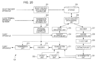
- Fig. 20 is a block diagram schematically illustrating a configuration of the transcoder 104 in this case.
- the transcoder 104 may convert arbitrary block sizes into the block sizes of 8 ⁇ 8 which conform to the JPEG standard.
- the transcoder 104 in the case of the example shown in Fig. 20 includes, in addition to the configuration in the case of the example shown in Fig. 7 , a determination unit 261, a 2D-IDCT unit 262, and a 2D-DCT unit 263.
- An output from the extraction unit 210 is supplied to the determination unit 261, and an output from the determination unit 261 is supplied to the quantization unit 211 or the 2D-IDCT unit 262.
- An output of the 2D-IDCT unit 262 is supplied to the 2D-DCT unit 263.
- An output of the 2D-DCT unit 263 is supplied to the quantization unit 211.
- the determination unit 261 supplies the 2D-DCT coefficient data of the blocks which is supplied from the extraction unit 210 to the quantization unit 211. That is, in this case, conversion of the block sizes which will be described below is omitted, and a quantization process is performed on the 2D-DCT coefficient data of the blocks which is extracted by the extraction unit 210.
- the determination unit 261 supplies the 2D-DCT coefficient data of the blocks which is supplied from the extraction unit 210 to the 2D-IDCT unit 262. That is, in this case, the 2D-DCT coefficient data of the blocks which is extracted by the extraction unit 210 is quantized after the block sizes of the 2D-DCT coefficient data are converted as described below.
- the 2D-IDCT unit 262 performs two-dimensional inverse orthogonal transform (2D-IDCT) on the 2D-DCT coefficient data of the blocks which is supplied from the determination unit 261 so as to obtain baseband image data.
- 2D-IDCT two-dimensional inverse orthogonal transform
- the 2D-DCT unit 263 performs two-dimensional orthogonal transform (2D-DCT) supplied from the 2D-IDCT unit 262 for each matrix of 8 pixels ⁇ 8 pixels which conforms to the JPEG standard. Note that, when block sizes of at least one of the X and Y directions of the 3D-DCT encoded data stored in the storage 103 are smaller than the block sizes of 8 ⁇ 8, the 2D-DCT unit 263 stores the baseband image data supplied from the 2D-IDCT unit 262 until data corresponding to the matrix of 8 pixels ⁇ 8 pixels which conforms to the JPEG standard is obtained. When the data corresponding to the matrix of 8 pixels ⁇ 8 pixels is obtained, the 2D-DCT unit 263 performs two-dimensional orthogonal transform on the data of 8 pixels ⁇ 8 pixels.
- 2D-DCT unit 263 performs two-dimensional orthogonal transform on the data of 8 pixels ⁇ 8 pixels.
- the 2D-DCT unit 263 supplies the 2D-DCT coefficient data (of the blocks) of the matrix of 8 pixels ⁇ 8 pixels (which conforms with the JPEG standard) which has been obtained through the orthogonal transform as described above to the quantization unit 211.
- the quantization unit 211 quantizes the 2D-DCT coefficient data of the blocks supplied from the determination unit 261 or the 2D-DCT unit 263 under control of the encoding parameter controller 203 and supplies the quantized 2D-DCT coefficient data of the blocks to the encoder 212.
- the transcoder 104 may convert the current block sizes into the block sizes of 8 ⁇ 8 which conform with the JPEG standard by returning the 2D-DCT coefficient data to the pixel space. Note that, also in this case, the transcoder 104 may extract data to be used by the extraction unit 210 and perform a block-size conversion process only on the extracted data. That is, unused data which is not supplied to the client terminal apparatus 105 may not be processed (may not be returned to the baseband).
- the transcoder 104 may easily change the block sizes at high speed. Accordingly, even when block sizes in an XY plane direction of 3D-DCT encoded data is not 8 ⁇ 8, the transcoder 104 may easily supply desired JPEG encoded data to the client terminal apparatus 105 at high speed.
- the 2D-IDCT unit 262 performs two-dimensional inverse orthogonal transform (2D-IDCT) on 2D-DCT coefficient data of blocks which is extracted in step S229 so as to obtain baseband image data.
- 2D-IDCT two-dimensional inverse orthogonal transform
- step S263 the 2D-DCT unit 263 performs two-dimensional orthogonal transform (2D-DCT) on the baseband image data obtained through the process in step S262 for each matrix of 8 pixels x 8 pixels (block sizes of 8 ⁇ 8) which conforms to the JPEG standard so as to obtain 2D-DCT coefficient data for each block. That is, the 2D-DCT coefficient data is obtained for each block having the block size of 8 ⁇ 8 through this process.
- the 2D-DCT unit 263 returns the process to step S230 and the processes in step S230 onwards are executed.
- the transcoder 104 appropriately converts only block sizes of data to be used even when block sizes in an XY plane direction of 3D-DCT coefficient data stored in the storage 103 is not 8 ⁇ 8 so as to generate 2D-DCT encoded data having block sizes conforming to the JPEG standard and supply the 2D-DCT encoded data to the client terminal apparatus 105.
- the transcoder 104 may easily supply desired JPEG encoded data at high speed to the client terminal apparatus 105 even when the block sizes in the XY plane direction of the 3D-DCT encoded data is not 8 ⁇ 8.
- block sizes of encoded data which is output by the transcoder 104 (and supplied to the client terminal apparatus 105) may be arbitrary determined. That is, as an encoding method for image data used when the data is supplied to the client terminal apparatus 105, the arbitrary encoding method other than the JPEG method may be used. Examples of the other arbitrary encoding method include MPEG2 (Moving Picture Experts Group 2), AVC (Advanced Video Coding), and HEVC (High Efficiency Video Coding).
- MPEG2 Motion Picture Experts Group 2
- AVC Advanced Video Coding
- HEVC High Efficiency Video Coding
- the transcoder 104 may convert image data into JPEG 2000 encoded data and supply the data to the client terminal apparatus 105.
- JPEG 2000 encoding method arbitrary block sizes are employed. Therefore, the block-size conversion process described above is omitted.
- an order of the inverse orthogonal transform process (an order of the inverse orthogonal transform process performed in the X, Y, and Z directions) does not depend on an order of the orthogonal transform process (an order of the orthogonal transform process performed in the X, Y, and Z directions). That is, the order of the orthogonal transform process (the order of the orthogonal transform process in the X, Y, and Z directions) performed by the 3D-DCT unit 134 included in the 3D-DCT encoder 102 is arbitrarily determined.
- the focus plane corresponds to the XY plane and the direction of the focal length corresponds to the Z direction in the foregoing description
- the X, Y, and Z directions may be arbitrarily determined as long as the X, Y, and Z directions orthogonally intersect with one another.
- the direction of the focal length may correspond to the X or Y direction.
- a direction of the inversion orthogonal conversion process performed by the 1D-IDCT unit 209 included in the transcoder 104 is orthogonal to a desired plane (supplied to the client terminal apparatus 105).
- Fig. 22 is a block diagram schematically illustrating a configuration of an image processing system according to a second embodiment of the present disclosure.
- an image processing system 300 shown in Fig. 22 which is used for cytoscreening, a tissue diagnosis, and the like captures a specimen using a virtual microscope 101, and an image of the specimen is observed using a client terminal apparatus 105.
- a Z-stack image obtained by the virtual microscope 101 is encoded in the JPEG method and is temporarily stored, and resultant JPEG encoded data is appropriately read and decoded for the observation. Then, after the observation, if the image is not to be referred to for a certain period of time, the JPEG encoded data is converted in a 3D-DCT encoding method into 3D-DCT encoded data to be stored in a middle and long term (archived).
- JPEG encoded data is converted into 3D-DCT encoded data in the image processing system 300.
- the image processing system 300 includes the virtual microscope 101, a JPEG encoder 302, a temporal storage 303, a transcoder 304, a long-term storage 305, and the client terminal apparatus 105.
- the JPEG encoder 302 performs JPEG encoding on focus plane images of a Z-stack image generated by the virtual microscope 101 so as to generate a JPEG encoded data group.
- the JPEG encoder 302 supplies the generated JPEG encoded data group to the temporal storage 303 which stores the JPEG encoded data.
- the temporal storage 303 including an arbitrary storage medium temporarily stores the JPEG encoded data obtained by encoding the focus plane images of the Z-stack image in the JPEG method.
- the temporal storage 303 supplies the JPEG encoded data to the client terminal apparatus 105 in response to a request from the client terminal apparatus 105.
- the observation of the specimen is generally performed within a comparatively short period of time after the Z-stack image of the specimen is generated by the virtual microscope 101. Then, while the specimen is observed, in general, the image is frequently requested by the client terminal apparatus 105. Note that the number of specimens which are simultaneously observed is comparatively small.
- the Z-stack image is stored in the temporal storage 303 as the JPEG encoded data which is easily supplied to the client terminal apparatus 105 (that is, which is not subjected to the conversion process and supplied at high speed to the client terminal apparatus 105) even if encoding efficiency (compression rate) is not excellent.
- the temporal storage 303 preferably performs reading and writing at higher speed even if the temporal storage 303 has a comparatively small storage capacity.
- JPEG encoded data is directly supplied from the temporal storage which enables high-speed reading to the client terminal apparatus 105 without being subjected to a conversion process.
- the image of the specimen is not frequently referred to.
- the image data should be stored in a long term such as five years.
- the transcoder 304 reads the JPEG encoded data to be stored in a long term from the temporal storage in order to improve the encoding efficiency and converts the JPEG encoded data into 3D-DCT encoded data.
- the transcoder 304 supplies the generated 3D-DCT encoded data to the long-term storage 305 which stores the 3D-DCT encoded data.
- the long-term storage 305 including an arbitrary storage medium stores the 3D-DCT encoded data supplied from the transcoder 304 in a medium to long term. Reading and writing speed of the long-term storage 305 may be slower than those of the temporal storage 303. However, storage capacity of the long-term storage 305 is preferably larger than that of the temporal storage 303.
- the encoding efficiency (compression rate) of the 3D-DCT encoded data is higher than that of the JPEG encoded data group corresponding to the 3D-DCT encoded data.
- the long-term storage 305 may store a number of images of the specimen larger than those of the temporal storage 303.
- the virtual microscope 101, the JPEG encoder 302, the temporal storage 303, the transcoder 304, and the long-term storage 305 included in a dotted frame 310 shown in Fig. 22 may be arbitrarily combined with one another.
- all the devices included in the dotted frame 310 may be configured as a single device (such as a server which supplies an image to the client terminal apparatus 105).
- Fig. 23 is a block diagram schematically illustrating a configuration of the client terminal apparatus 302 shown in Fig. 22 .
- the JPEG encoder 302 includes a 2D-DCT unit 321, a quantization unit 322, and an encoder 323.
- the 2D-DCT unit 321 performs a two-dimensional discrete cosine transform process on the focus plane images of the Z-stack image so as to generate 2D-DCT coefficient data for each block.
- the quantization unit 322 quantizes the 2D-DCT coefficient data of the blocks which is generated by the 2D-DCT unit 321.
- the encoder 323 performs the run-length Huffman encoding on the 2D-DCT coefficient data of the blocks which is quantized by the quantization unit 322 so as to generate JPEG encoded data for each block.
- the encoder 323 supplies the generated JPEG encoded data of the blocks to the temporal storage 303 which stores the JPEG encoded data.
- Fig. 24 is a block diagram schematically illustrating a configuration of the transcoder 304 shown in Fig. 22 .
- the transcoder 304 includes a decoder 341, an inverse quantization unit 342, an 1D-DCT unit 343, a quantization unit 344, and an encoder 345.
- the decoder 341 reads the JPEG encoded data of the blocks from the temporal storage 303 and performs the run-length Huffman decoding to obtain quantized 2D-DCT coefficient data of the blocks to be supplied to the inverse quantization unit 342.
- the inverse quantization unit 342 performs inverse quantization on the quantized 2D-DCT coefficient data of the blocks which is supplied from the decoder 341 and supplies obtained resultant 2D-DCT coefficient data of the blocks to the 1D-DCT unit 343.
- the 1D-DCT unit 343 performs 1D-DCT in the Z direction on the 2D-DCT coefficient data of the blocks which has been subjected to the inverse quantization performed by the inverse quantization unit 342 and supplies obtained resultant 3D-DCT coefficient of the blocks data to the quantization unit 344.
- the quantization unit 344 quantizes the supplied 3D-DCT coefficient data of the blocks which is to be supplied to the encoder 345.
- the encoder 345 performs the run-length Huffman encoding on the quantized 3D-DCT coefficient data of the blocks so as to generate 3D-DCT encoded data of the blocks.
- the encoder 345 supplies the generated 3D-DCT encoded data of the blocks to the long-term storage 305 which stores the 3D-DCT encoded data.
- the 2D-DCT unit 321 included in the JPEG encoder 302 performs 2D-DCT for individual blocks on the focus plane images of the Z-stack image supplied from the virtual microscope 101 or the like in step S301.
- the quantization unit 322 quantizes the 2D-DCT coefficient data of the blocks.
- the encoder 323 performs the run-length Huffman encoding on the quantized 2D-DCT coefficient data of the blocks.
- the encoder 323 supplies the generated 2D-DCT encoded data of the blocks to the temporal storage 303 which temporarily stores the 2D-DCT encoded data.
- step S304 After the process in step S304 is terminated, the temporal storage process is terminated.
- step S321 the decoder 341 reads the 2D-DCT encoded data of the blocks from the temporal storage 303. In step S322, the decoder 341 decodes the 2D-DCT encoded data of the blocks.
- step S323 the inverse quantization unit 342 performs inverse quantization on the quantized 2D-DCT efficient data of the blocks.
- step S324 the 1D-DCT unit 343 performs 1D-DCT in the Z direction on 2D-DCT efficient data group of the blocks.
- step S325 the quantization unit 344 quantizes 3D-DCT coefficient data of the blocks.
- step S326 the encoder 345 encodes the quantized 3D-DCT coefficient data of the blocks.
- step S327 the encoder 345 supplies the generated 3D-DCT encoded data of the blocks to the long-term storage 305 which stores the 3D-DCT encoded data.
- the transcoder 304 terminates the long-term storage process.
- the image processing system 300 may reduce capacity used for storage of encoded data obtained by encoding an image while usability of an image is prevented from being deteriorated.
- an encoding method of image data to be supplied to the client terminal apparatus 105 is arbitrarily determined, and image data to be stored in the temporal storage 303 may be encoded by an encoding method other than the JPEG method.
- the image data may be subjected to an arbitrary orthogonal transform process such as wavelet transform.
- the temporal storage 303 may store image data encoded in the JPEG 2000 method.
- images of an image used for cytoscreening or a tissue diagnosis is stored as 3D-DCT encoded data or supplied as JPEG encoded data
- content and usage of the image may be arbitrarily determined and an image which is not used as described above may be employed.
- image representing map information may be employed.
- images of an image group which is subjected to 3D-DCT and which corresponds to the Z-stack image described above preferably have the high correlations with one another.
- the image data is generated by the virtual microscope 101
- a method for generating image data is arbitrarily determined, and the image data may be generated by a device such as a digital still camera instead of the virtual microscope 101.
- block sizes in an XY plane (focus plane) of the 3D-DCT encoded data to be stored in the long-term storage 305 may be arbitrarily determined and may not be 8 ⁇ 8.
- An example of a configuration of the transcoder 304 when the block sizes are not determined to be 8 ⁇ 8 will be schematically shown in Fig. 27 .
- the transcoder 304 shown in Fig. 27 includes, in addition to the configuration in the case described with reference to Fig. 24 , a DCT block-size converter 351.
- An output of the inverse quantization unit 342 is supplied to the DCT block-size converter 351.
- an output of the DCT block-size converter 351 is supplied to the 1D-DCT unit 343.
- the DCT block-size converter 351 performs a process the same as those performed by the 2D-IDCT unit 262 and the 2D-DCT unit 263 shown in Fig. 20 and returns the 2D-DCT coefficient data of the blocks to the pixel space so that the block sizes of 8 ⁇ 8 which conform to the JPEG standard are converted into arbitrary block sizes.
- the DCT block-size converter 351 may convert the block sizes of the 2D-DCT coefficient data of the blocks in the frequency space similarly to the DCT block size converter 252.
- the DCT block-size converter 351 supplies the 2D-DCT coefficient data obtained after the block-size conversion to the 1D-DCT unit 343.
- the 1D-DCT unit 343 performs 1D-DCT in the Z direction on the 2D-DCT coefficient data of the blocks and supplies obtained resultant 3D-DCT coefficient data to the quantization unit 344.
- the DCT block-size converter 351 may convert the block sizes of the 2D-DCT coefficient data. Accordingly, the transcoder 304 may generate 3D-DCT encoded data having desired block sizes from JPEG encoded data.
- Fig. 28 is a flowchart illustrating an example of a flow of a long-term storage process in this case. Also in this case, the flow of the long-term storage process is the basically the same as that described with reference to the flowchart shown in Fig. 26 .
- step S323 After the process in step S323 is terminated, the process proceeds to step S351.
- step S351 the DCT block-size converter 351 converts block sizes of 8 ⁇ 8 of 2D-DCT coefficient data of blocks obtained through inverse quantization performed in a process of step S323 into desired block sizes. After the block sizes are converted, the DCT block-size converter 351 returns the process to step S324 and the processes in step S324 onwards are executed.
- the transcoder 304 may generate 3D-DCT encoded data having desired block sizes from JPEG encoded data.
- block sizes of encoded data stored in the temporal storage 303 may be arbitrarily determined and therefore may be other than 8 ⁇ 8. That is, the encoded data stored in the temporal storage 303 may be encoded in an encoding method other than the JPEG method. Examples of the encoding method include MPEG2, AVC, and HEVC.
- a determination as to whether the DCT block-size converter 351 included in the transcoder 304 converts block sizes may be selectively made in accordance with an arbitrary condition where appropriate. Furthermore, the DCT block-size converter 351 may determine block sizes (the DCT block-size converter 351 may arbitrarily set block sizes after conversion).
- the DCT block-size converter 351 may not convert block sizes (block sizes of 8 ⁇ 8 remain as they are, for example) and supply 2D-DCT coefficient data to the 1D-DCT unit 343 whereas when improvement of encoding efficiency has priority, the DCT block-size converter 351 may change the block sizes (to block sizes of 32 ⁇ 32 or 64 ⁇ 64, for example).
- a series of the processes described above may be executed by hardware or software.
- a personal computer shown in Fig. 29 may be configured, for example.
- a CPU Central Processing Unit
- ROM Read Only Memory
- RAM Random Access Memory
- the CPU 401, the ROM 402, and the RAM 403 are connected to one another through a bus 404.
- An input/output interface 410 is also connected to the bus 404.
- an input unit 411 including a keyboard and a mouse
- an output unit 412 including a display such as a CRT (Cathode Ray Tube) or an LCD (Liquid Crystal Display) and a speaker
- the storage unit 413 including a hard disk
- a communication unit 414 including a modem are connected to the input/output interface 410.
- the communication unit 414 performs a communication process through a network including the Internet.
- a drive 415 is also connected to the input/output interface 410, and a removable medium 421 such as a magnetic disk, an optical disc, a magneto-optical disc, or a semiconductor memory is appropriately inserted into the drive 415.
- a removable medium 421 such as a magnetic disk, an optical disc, a magneto-optical disc, or a semiconductor memory is appropriately inserted into the drive 415.
- Computer programs read from the removable medium 421 are installed in the storage unit 413 where appropriate.
- a program constituting the software is installed through the network or from a recording medium.
- the recording medium includes the removable medium 421 such as a magnetic disk (including a flexible disk), an optical disc (including a CD-ROM (Compact Disc-Read Only Memory) and a DVD (Digital Versatile Disc)), a magneto-optical disc (including MD (Mini Disc)) and a semiconductor memory which include programs to be distributed to deriver the programs to users and which are provided separately from the apparatus body as shown in Fig. 29 and the ROM 402 and a hard disk included in the storage unit 413 which include programs recorded therein which are delivered to the users in a state in which the ROM 402 and the hard disk are incorporated in the apparatus body in advance.
- a magnetic disk including a flexible disk
- an optical disc including a CD-ROM (Compact Disc-Read Only Memory) and a DVD (Digital Versatile Disc)
- MD Magneto-optical disc
- semiconductor memory which include programs to be distributed to deriver the programs to users and which are provided separately from the apparatus body as shown in Fig. 29 and the
- programs may be executed by the computer in a time-series manner in an order described herein, may be executed in parallel, or may be executed where appropriate when the programs are called, for example.
- a step of describing a program recorded in the recording medium includes processes performed in the time-series manner in the order described herein, processes performed in parallel, and processes executed separately from one another.
- system represents an entire apparatus including a plurality of devices (units).
- a configuration described as a single device (or processing unit) in the foregoing description may be divided into a plurality of devices (or processing units).
- a configuration including a plurality of devices (or processing units) in the foregoing description may be collectively configured as a single device (or processing unit).
- other configurations may be added to the configurations of the devices (or processing units).
- part of the configuration of one of the devices (or one of the processing units) may be included in a configuration of one of the other devices (or one of the other processing units) as long as the configuration and operation of the entire system are substantially not changed. That is, the embodiments of the present disclosure are not limited to the foregoing embodiments and various modifications may be made without departing from the scope of the present disclosure.
Landscapes
- Engineering & Computer Science (AREA)
- Multimedia (AREA)
- Signal Processing (AREA)
- Physics & Mathematics (AREA)
- Discrete Mathematics (AREA)
- General Physics & Mathematics (AREA)
- Compression Or Coding Systems Of Tv Signals (AREA)
- Compression Of Band Width Or Redundancy In Fax (AREA)
- Image Processing (AREA)
- Investigating Or Analysing Materials By Optical Means (AREA)
- Image Analysis (AREA)
Description
- The present disclosure relates to image processing apparatuses and image processing methods, and particularly relates to an image processing apparatus and an image processing method which are capable of reducing a capacity for storing encoded data obtained by encoding images.
- In recent years, in a field of a pathological diagnosis such as so-called cytoscreening and a tissue diagnosis, a digital pathological diagnosis has been performed using a virtual microscope.
- The virtual microscope is an apparatus including a microscope device capable of obtaining image data and a computer which processes the image data. The virtual microscope captures an entire slide glass on which a sample (specimen) is placed and stores a microscopic image of the sample as a digital image.
- By this, higher-level microscopic observation may be performed by appropriately performing image processing on the microscopic image of the sample and displaying the processed image on a display of a personal computer, for example, when compared with a case where a normal microscope is used for the observation of the specimen. For example, the image processing may be performed on the microscopic image so that the specimen is clearly viewed. Furthermore, a portion of the microscopic image may be enlarged for display, for example. Moreover, microscopic observation through the Internet may be performed.
- In general, specimens used in a pathological diagnosis such as cytoscreening and a tissue diagnosis have thicknesses of themselves. Therefore, data of an image (Z-stack image) obtained by capturing such a specimen from a plurality of focus planes should be obtained to obtain a 3D structure of the specimen.
- Note that, since a large capacity is used for uncompressed image data, it is difficult to store and manage the uncompressed image data. Therefore, in the Digital Imaging and Communication in Medicine (DICOM) standard, the JPEG (Joint Photographic Experts Group) is employed as a codec format for such digital microscopic image data.
- However, also in this case, since a plurality of JPEG data should be obtained for a single specimen, a large capacity is used for storing and managing the data. Accordingly, an amount of data should be reduced.
- For example, a compression method for a plurality of focus plane images using interframe encoding in which differences between adjacent frames are obtained has been proposed. Furthermore, a method for determining a focus plane serving as a reference and performing compression using blur compensating prediction utilizing a blur change obtained in accordance with an optical parameter and a Z coordinate displacement from the reference focus plane has been proposed (refer to Japanese Unexamined Patent Application Publication No.
2007-11977 - Here, in a system using the virtual microscope described above, a portion of microscopic image data which has been stored is displayed as an observation image. In this case, a quick response (display) should be performed in response to specifying of a position and a size of the portion to be displayed.
- However, in the method disclosed in Japanese Unexamined Patent Application Publication No.
2007-11977 2007-11977 - Furthermore, for example, when the encoded data is decoded by the server and thereafter an image is transmitted to the terminal apparatus, an amount of data to be transmitted is increased. Therefore, response may become slow due to transmission delay and the like.
- Accordingly, it is desirable to reduce capacity used for storing encoded data obtained by encoding an image while deterioration of usability of the image is suppressed.
- BASKURT A ET ALL: "3-DIMENSIONAL IMAGE COMPRESSION BY DISCRETE COSINE TRANSFORM", SIGNAL PROCESSING: THEORIES AND APPLICATIONS. GRENOBLE, SEPT. 5 - 8, 1988; [PROCEEDINGS OF THE EUROPEAN SIGNAL PROCESSING CONFERENCE (EUSIPCO)], AMSTERDAM, NORTH HOLLAND, NL, discloses an adaptive coding method using a three-dimensional transform 3-D discrete Cosine Transform (3-D DCT) is performed on NxNxN blocks. Positions of transform coefficients are coded using an Octree representation. This method is applied on a set of human heart slices corresponding to a same instant of the ECG (3-D image application) and on an image sequence corresponding to the same slice recorded at various instants of the ECG (2-D moving image sequence application).
- CHAN K K ET AL: "Three-dimensional transform compression of images from dynamic studies", PROCEEDINGS OF SPIE, SPIE, vol. 1232, 1 January 1990 (1990-01-01), pages 322-326, discloses transform based compression methods that achieve their effect by taking advantage of the correlations between adjacent pixels in an image. The increasing use of three-dimensional imaging studies in radiology requires new techniques for image compression. For time-sequenced studies such as digital subtraction angiography, pixels are correlated between images, as well as within an image. By using three-dimensional cosine transforms, correlations in time as well as space can be exploited for image compression. Sequences of up to eight 512 x 512 x 8-bit images are compressed using a single full-volume three-dimensional cosine transform, followed by quantization and bit-allocation. The quantization process is a uniform thresholding type and an adaptive three-dimensional bit-allocation table is used. The resultant image fidelity vs. compression ratio is shown to be superior to that achieved by compressing each image individually.
- LUIS URBANO ET ALL: "3-Dimensional medical image compression: A first approach to the application of the ADCT-ISO", ENGINEERING IN MEDICINE AND BIOLOGY SOCIETY, 1988.
- PROCEEDINGS OF THE ANNUAL INTERNATIONAL CONFERENCE OF THE IEEE, IEEE, NEW YORK, NY, USA, 29 October 1992 (1992-10-29), pages 1219-1220 discloses an application of the ADCT-ISO method using a three-dimensional transform. In this first approach, a block size 8x8x8 was chosen. The multidimensional DCT was developed from the 1D DCT fast algorithm. Quantized coefficient values are obtained using a linear transformed quantization step dependent on the spectral position of the coefficient. These steps are given by the 3D quantization matrix which has been derived empirically from the 2D matrix. Information on the value and position of the coefficients are transmitted performing entropy coding (Huffman's Code). Performance was evaluated on a MRI and
CT 3D isotropic image data base. Five compression ratios were defined: 0.20, 0.30, 0.40, 0.50, and 0.80 bits/pixel. The preliminary image fidelity results (SNRmse) obtained suggest that it is possible to obtain higher compression ratios in 3D than in 2D. - RAMASWAMY A ET AL: "A Mixed Transform Approach for Efficient Compression of Medical Images", IEEE TRANSACTIONS ON MEDICAL IMAGING, IEEE SERVICE CENTER, PISCATAWAY, NJ, US, vol. 15, no. 3, 1 June 1996 (1996-06-01), discloses a technique to compress medical data employing two or more mutually nonorthogonal transforms. Both lossy and lossless compression implementations are considered. The signal is first resolved into subsignals such that each subsignal is compactly represented in a particular transform domain. An efficient lossy representation of the signal is achieved bu superimposing the dominant coefficients corresponding to each subsignal. The residual error, which is the difference between the original signal and the reconstructed signal is properly formulated. Adaptive algorithms in conjunction with an optimization strategy are developed to minimize this error. Both two-dimensional (2-D) and three-dimensional (3-D) approaches for the technique are developed. It is shown that for a given number of retained coefficients, the discrete cosine transform (DCT)-Walsh mixed transform representation yields a more compact representation than using DCT or Walsh alone. This lossy technique is further extended for the lossless case. The coefficients are quantized and the signal is reconstructed. The resulting reconstructed signal samples are rounded to the nearest integer and the modified residual error is computed. This error is transmitted employing a lossless technique such as the Huffman coding. It is shown that for a given number of retained coefficients, the mixed transforms again produces the smaller rms-modified residual error. The first-order entropy of the error is also smaller for the mixed-transforms technique than for the DCT, thus resulting in smaller length Huffman codes.
ROESE J A ET AL: "INTERFRAME COSINE TRANSFORM IMAGE CODING", IEEE TRANSACTIONS ON COMMUNICATIONS, IEEE SERVICE CENTER, PISCATAWAY, NJ, USA, vol. 25, no. 11, 1 November 1977 (1977-11-01), pages 1329-1339, discloses two-dimensional transform coding and hybrid transform/DPCM coding techniques for image coding. This paper presents a theoretical and experimental extension of these techniques to the coding of sequences of correlated image frames. Two coding methods are analyzed: three-dimensional cosine transform coding, and two-dimensional cosine transform coding within an image frame combined with DPCM coding between frames. Theoretical performance estimates are developed for the coding of Mazkovian image sources. Simulation results are presented for transmission over error-free and binary symmetric channels. -
US-A-5,289,289 disclose an image data coding apparatus that has an image pickup system for generating at least dynamic images. The apparatus further comprises a data processing section, two transforming sections, a quantizing section, and a coding section. The data processing section three-dimensionally arranges image data for several adjoining frames among the dynamic image data as three-dimensional image data, divides the three-dimensional image data into several three-dimensional blocks with a specified size, and outputs each three-dimensional block data. The first transforming section applies three-dimensional block data and outputs three-dimensional transform coefficient data. The second transforming section transforms the three-dimensional transform coefficient data. The quantizing section quantizes the one-dimensionally-arranged transform coefficient data with a specified quantization width and generates quantization output. The coding section codes the quantization output and generates coding output. - The transform unit may include a decoder configured to decode the three-dimensional orthogonal transform encoded data by a decoding method corresponding to an encoding method for the three-dimensional orthogonal transform coefficient data encoder, an one-dimensional inverse orthogonal transform unit configured to perform one-dimensional inverse orthogonal transform in a direction in which the images are arranged on the three-dimensional orthogonal transform coefficient data obtained by decoding the three-dimensional orthogonal transform encoded data using the encoder, and a two-dimensional orthogonal transform coefficient data encoder configured to encode the two-dimensional orthogonal transform coefficient data obtained by performing the inverse orthogonal transform on the three-dimensional orthogonal transform coefficient data using the one-dimensional inverse orthogonal transform unit.
- The transform unit may further include an extraction unit configured to extract two-dimensional orthogonal transform coefficient data including a desired image from among a plurality of the two-dimensional orthogonal transform coefficient data obtained by performing the inverse orthogonal transform on the three-dimensional orthogonal transform coefficient data using the one-dimensional inverse orthogonal transform unit, and the two-dimensional orthogonal transform coefficient data encoder encodes the two-dimensional orthogonal transform coefficient data extracted by the extraction unit.
- The image processing apparatus may further include a block-size conversion unit configured to convert block sizes, each of which serves as a unit of the two-dimensional orthogonal transform process, of the two-dimensional orthogonal transform coefficient data extracted by the extraction unit. The two-dimensional orthogonal transform coefficient data encoder may encode the two-dimensional orthogonal transform coefficient data obtained through the block-size conversion performed by the block-size conversion unit.
- The block-size conversion unit obtains the two-dimensional orthogonal transform coefficient data which has been subjected to the block size conversion by converting the block sizes in a frequency space.
- The block-size conversion unit may convert sizes of the blocks after the two-dimensional orthogonal transform coefficient data is subjected to two-dimensional orthogonal transform so that baseband image data is obtained, and obtain the two-dimensional orthogonal transform coefficient data which has been subjected to the block size conversion by performing two-dimensional orthogonal transform on the obtained baseband image data which has been subjected to the block size conversion.
- Accordingly, images are processed. Especially, capacity used to store encoded data obtained by encoding an image may be reduced while usability of the image is prevented from being deteriorated.
- Further particular and preferred aspects of the present invention are set out in the accompanying independent and dependent claims. Features of the dependent claims may be combined with features of the independent claims as appropriate, and in combinations other than those explicitly set out in the claims.
- Embodiments of the disclosure will now be described, by way of example only, with reference to the accompanying drawings in which:
-
Fig. 1 is a block diagram schematically illustrating a configuration of an image processing system according to a first embodiment of the present disclosure; -
Fig. 2 is a diagram illustrating an operation of a virtual microscope; -
Fig. 3 is a block diagram schematically illustrating a configuration of a 3D-DCT encoding apparatus; -
Fig. 4 is a diagram illustrating 3D-DCT; -
Figs. 5A and 5B are diagrams illustrating distribution of DCT coefficients of 3D-DCT; -
Fig. 6 is a diagram illustrating a state of z-correlation; -
Fig. 7 is a block diagram schematically illustrating a configuration of a transcoder; -
Fig. 8 is a diagram illustrating a configuration of stored data; -
Fig. 9 is a block diagram schematically illustrating a configuration of a client terminal apparatus; -
Fig. 10 is a diagram illustrating 3D-DCT encoding process; -
Fig. 11 is a flowchart illustrating an encoding parameter setting process; -
Fig. 12 is a flowchart illustrating a correlation process; -
Fig. 13 is a flowchart illustrating a focus flag setting process; -
Fig. 14 is a flowchart illustrating a 3D-DCT-encoded-data storing process; -
Fig. 15 is a flowchart illustrating an image supplying/displaying process; -
Fig. 16 is a flowchart illustrating an image process; -
Fig. 17 is a block diagram schematically illustrating another configuration of the transcoder; -
Fig. 18 is a diagram illustrating a state of block-size conversion; -
Fig. 19 is a flowchart illustrating another image supplying/displaying process; -
Fig. 20 is a block diagram schematically illustrating a further configuration of the transcoder; -
Fig. 21 is a flowchart illustrating a further image supplying/displaying process; -
Fig. 22 is a block diagram schematically illustrating a configuration of an image processing system according to a second example embodiment of the present disclosure; -
Fig. 23 is a block diagram schematically illustrating a configuration of a JPEG encoder; -
Fig. 24 is a block diagram schematically illustrating a configuration of a transcoder; -
Fig. 25 is a flowchart illustrating a temporal storage process; -
Fig. 26 is a flowchart illustrating a long-term storage process; -
Fig. 27 is a block diagram schematically illustrating another configuration of the transcoder; -
Fig. 28 is a flowchart illustrating another long-term storage process; and -
Fig. 29 is a block diagram schematically illustrating a configuration of a personal computer according to a third example embodiment of the present disclosure. - Modes for carrying out the present disclosure (hereinafter referred to as "embodiments") will be described hereinafter. Note that a description will be made in the following order.
- 1. First Embodiment (Image Processing System)
- 2. Second Embodiment (Image Processing System)
- 3. Third Embodiment (Personal Computer)
- 1. First Embodiment
-
Fig. 1 is a block diagram schematically illustrating a configuration of an image processing system according to a first embodiment of the present disclosure. - An
image processing system 100 shown inFig. 1 which is used for cytoscreening and a tissue diagnosis, for example, captures a specimen, encodes digital image data to be stored and managed, decodes a portion of the digital image data where appropriate, and displays an image of the specimen corresponding to the portion of the digital image data. - As shown in
Fig. 1 , theimage processing system 100 includes avirtual microscope 101, a 3D-DCT (3 Dimensional-Discrete Cosine Transform)encoder 102, astorage 103, atranscoder 104, and aclient terminal apparatus 105. - In general, specimens used in pathological diagnoses such as cytoscreening and tissue diagnoses have thicknesses of themselves.
- The
virtual microscope 101 captures such a specimen from a plurality of focus positions (by changing a Z coordinate of a focus position) so as to obtain a plurality of images (several tens of images, for example) (hereinafter also referred to as "focus plane images"). That is, a plurality of captured images (focus plane images) are generated from a single specimen (a cell group sandwiched by a pair of slid glasses, for example). Then, the plurality of captured images correspond to the different focus positions. Hereinafter, such a group of the captured images (focus plane images) is referred to as a "Z-stack image". - Referring back to
Fig. 1 , thevirtual microscope 101 captures a specimen so as to generate a Z-stack image and supplies the Z-stack image to the 3D-DCT encoder 102. - The 3D-
DCT encoder 102 performs encoding including 3-dimensional discrete cosine transform so as to generate 3D-DCT encoded data. The 3-dimensional discrete cosine transform will be described hereinafter. - The 3D-
DCT encoder 102 supplies the generated 3D-DCT encoded data through thetranscoder 104 to thestorage 103 which stores (holds) the 3D-DCT encoded data. Note that the 3D-DCT encoder 102 may supply the 3D-DCT encoded data to thestorage 103 which stores (holds) the 3D-DCT encoded data without using thetranscoder 104. - A user who performs a diagnosis of the specimen operates the
client terminal apparatus 105 so that theclient terminal apparatus 105 displays an image of the specimen captured by thevirtual microscope 101 as an observation image. Theclient terminal apparatus 105 requests thetranscoder 104 to transmit an image to be displayed in accordance with the user's operation or the like. For example, theclient terminal apparatus 105 specifies a position of a portion to be displayed as the observation image, a focus position, a resolution, and the like. - The
transcoder 104 obtains the 3D-DCT encoded data including the image requested by theclient terminal apparatus 105 from thestorage 103, performs a conversion process so as to generate JPEG encoded data representing the image requested by theclient terminal apparatus 105, and supplies the JPEG encoded data to theclient terminal apparatus 105. - When receiving the JPEG encoded data, the
client terminal apparatus 105 decodes the JPEG encoded data and displays the JPEG encoded data as the observation image. As described above, theimage processing system 100 may display the arbitrary portion of the Z-stack image (part of or the entire image) stored in thestorage 103 as the observation image in a monitor of theclient terminal apparatus 105. - As described above, the
image processing system 100 causes the 3D-DCT encoder 102 to encode the Z-stack image and causes thestorage 103 to store the 3D-DCT encoded data. Specifically, since compression utilizing the correlations among the focus plane images is performed also in a focus direction (Z direction), an amount of information is reduced. That is, theimage processing system 100 may reduce capacity used to store the Z-stack image (3D-DCT encoded data) in thestorage 103, and accordingly, reduce a load applied to thestorage 103. - Furthermore, 2-dimensional discrete cosine transform coefficient data (2D-DCT coefficient data) may be generated from the 3D-DCT encoded data without decoding the entire 3D-DCT encoded data to the baseband. Specifically, the
transcoder 104 may easily generate JPEG image data requested by theclient terminal apparatus 105 from the 3D-DCT encoded data stored in thestorage 103. Accordingly, theimage processing system 100 may reduce a load caused by the conversion process. - Furthermore, the conversion process may be performed by the
transcoder 104 which supplies an image (on a server side), theimage processing system 100 may reduce a load applied to theclient terminal apparatus 105. - Moreover, in the
image processing system 100, an image is transmitted from thetranscoder 104 to theclient terminal apparatus 105 as JPEG encoded data. Accordingly, theimage processing system 100 reduces an amount of data to be transmitted and reduces a load applied at the time of the transmission. Furthermore, since JPEG encoded data is transmitted, even a generalclient terminal apparatus 105 may receive the data from thetranscoder 104 and display an image. That is, theclient terminal apparatus 105 is not necessary to newly support a special encoding method, and therefore, general versatility is improved. - As described above, since 3D-DCT encoded data is easily decoded and transmitted, when the 3D-DCT encoded data is stored in the
storage 103, speed of a response of theimage processing system 100 to a request from theclient terminal apparatus 105 may be improved. - Note that the devices included in a
dotted frame 110 shown inFig. 1 may be arbitrarily combined with one another. For example, the 3D-DCT encoder 102 to thetranscoder 104 may be configured as a server (single device) which supplies an image to theclient terminal apparatus 105. Alternatively, thevirtual microscope 101 may be included in the server. It is apparent that other combinations may be employed. -
Fig. 3 is a block diagram schematically illustrating a configuration of the 3D-DCT encoder 102 shown inFig. 1 . As shown inFig. 3 , the 3D-DCT encoder 102 includes an encodingparameter setting unit 131, acorrelation processor 132, an encodingparameter setting unit 133, a 3D-DCT unit 134, aquantization unit 135, and anencoder 136. - The encoding
parameter setting unit 131 sets encoding parameters such as block sizes and quantization parameters in accordance with the Z-stack image supplied from thevirtual microscope 101. Thecorrelation processor 132 checks the correlation of the Z-stack image (the correlation among the focus plane images) in a Z direction supplied from thevirtual microscope 101 and deletes focus plane images which have low correlations between the others. The encodingparameter setting unit 133 determines whether the specimen included in the focus plane images of the Z-stack image supplied from thevirtual microscope 101 is focused and generates focus flags representing whether the specimen is focused. - The 3D-
DCT unit 134 performs 3-dimensional discrete cosine transform (3D-DCT) on the Z-stack image supplied from thevirtual microscope 101. -
Fig. 4 briefly illustrates the 3-dimensional discrete cosine transform (3D-DCT). Assuming that the focus plane images included in the Z-stack image are constituted in an XY plane and focus positions of the focus plane images are located on a Z axis, as shown in a right portion inFig. 4 , the images included in the Z-stack image are arranged in an XYZ space. - Also in a case of 3-dimensional discrete cosine transform, a process is performed for individual predetermined blocks. However, in the case of 3-dimensional discrete cosine transform, as shown in
Fig. 4 , the process is performed for individual 3-dimensional pixel blocks. InFig. 4 , "DCT_SIZE_X" denotes sizes of the 3-dimensional pixel blocks in an X direction (that is, processing units in the X direction), "DCT_SIZE_Y" denotes sizes of the 3-dimensional pixel blocks in a Y direction (that is, processing units in the Y direction), and "DCT_SIZE_Z" denotes sizes of the 3-dimensional pixel blocks in a Z direction (that is, processing units in the Z direction). - The
quantization unit 135 quantizes coefficient data (3D-DCT coefficient data) generated by the 3D-DCT unit 134. For example, thequantization unit 135 quantizes 3D-DCT coefficient data using the quantization parameters set by a quantizationparameter setting unit 143 included in the encodingparameter setting unit 131. - The
encoder 136 performs run-length Huffman encoding on the quantized 3D-DCT coefficient data so as to generate 3D-DCT encoded data. Theencoder 136 supplies the generated 3D-DCT encoded data to the transcoder 104 (shown inFig. 1 ). - Instead of use of a unit of a 2-dimensional XY pixel block employed in the JPEG, aggregative redundancy is eliminated using a unit of a 3-dimensional XYZ pixel block, and accordingly, the 3D-
DCT encoder 102 may improve encoding efficiency (compression rate). - The 3-dimensional discrete cosine transform (3D-DCT) is merely used in general moving-image codec. When general moving images are captured, since an object moves or is changed with time, the correlation in a time direction represented by the third axis (Z direction in this case) is low. It is difficult to improve the encoding efficiency (compression rate) even when the 3-dimensional discrete cosine transform is performed on such an image. However, in a case of the Z-stack image, since the focus plane images are obtained by only changing a focus plane viewed from the same observing point, the high correlation is obtained among the focus plane images. Accordingly, by removing the redundancy in the Z direction using the 3D-DCT as described above, the 3D-
DCT encoder 102 may improve the encoding efficiency (compression rate). - Returning back to
Fig. 3 , the encodingparameter setting unit 131 includes animage analysis unit 141, a block-size determination unit 142, and the quantizationparameter setting unit 143. - The
image analysis unit 141 analyzes the focus plane images of the Z-stack image supplied from thevirtual microscope 101. The block-size determination unit 142 determines sizes of 3D pixel blocks (sizes in X, Y, and Z directions) in accordance with a result of the analysis. The quantizationparameter setting unit 143 sets quantization parameters in accordance with the analysis result. - Note that, after the block-
size determination unit 142 determines the sizes of the 3D pixel blocks, processes are performed for individual 3D pixel blocks. Specifically, the setting of the quantization parameters using the quantizationparameter setting unit 143 is performed for individual blocks. Processes of thecorrelation processor 132, the encodingparameter setting unit 133, the 3D-DCT unit 134, thequantization unit 135, and theencoder 136 which are arranged in the latter stage are similarly performed. Note that the quantizationparameter setting unit 143 may set the quantization parameters in a unit of a Z-stack image, in a unit of a sequence, or the like, which is larger than a unit of a block. - For example, in general, an image used for cytoscreening is divided into a cell portion to be observed and the other portion. The cell portion mainly includes high frequency components whereas the other portion which may not include anything mainly includes low frequency components. Furthermore, due to its object, the cell portion to be observed has a high degree of importance and preferably has high image quality even though a coding amount is increased. On the other hand, the other portion is not to be observed and has a low degree of importance. Accordingly, a small coding amount is preferably attained even though image quality is low.
- Therefore, the block-
size determination unit 142 sets sizes of blocks included in a region which includes an object to be observed such as a cell (region of interest) to be small so as to suppress deterioration of image quality due to encoding. Furthermore, the block-size determination unit 142 sets sizes of blocks included in a region which does not include the object to be observed such as a cell (region of uninterest) to be large so as to reduce the encoding amount and improve the encoding efficiency (compression rate). - Although depending on a captured image (an object to be observed), in general, when a block size becomes large, encoding efficiency is improved. However, when a size of a block is too large, it is highly possible that the block includes a high-frequency component such as an edge. Accordingly, deviation in the vicinity of a direct current (DC) component of orthogonal transform coefficient data becomes small, and as a result, the encoding efficiency may be deteriorated. Furthermore, since the high frequency components are cut at a time of quantization, an undesired blur may be generated in the vicinity of the edge of a decoded image.
- In terms of the compression efficiency and subjective image-quality evaluation, in general, block sizes (DCT_SIZE_X and DCT_SIZE_Y) on a focus plane image plane are preferably approximately 32 pixels or approximately 64 pixels. The block sizes may be appropriately changed in the focus planes in accordance with edge information or the like included in the blocks. Note that, when transcoding is performed at high speed to obtain JPEG data, an expression "DCT_SIZE_X=DCT_SIZE_Y=8" is preferably satisfied. Furthermore, a unit of orthogonal transform processing (DCT_SIZE_Z) on a focus axis may be set in accordance with a capturing duration (pitch) and a depth of field at a time of image capturing.
- Furthermore, in general, when the correlation in the Z direction (focus axis direction) is high, data which has been subjected to the 3-dimensional discrete cosine transform (3D-DCT(DATA)) has a distribution characteristic in which a large DCT coefficient value is generated in a DC (direct current) component (3D block origin) and a coefficient value of an AC (alternate current) component becomes smaller as a position becomes far from the 3D block origin. Here, coefficient values in a high-frequency region in the Z direction are small and large coefficient values are mainly distributed in the vicinity of positions represented by (X, Y, Z) = (0, 0, Z).
- In this case, when high frequencies in the Z direction are removed in addition to high frequencies in the X and Y directions, the encoding efficiency (compression rate) can be improved while visible deterioration is suppressed. Accordingly, when correlation in the Z direction is high, a 3D quantization matrix has a distribution characteristic in which the values shown in
Fig. 5A are inversed. That is, small quantization values are assigned to portions in the vicinity of the 3D block origin having the large coefficient value whereas large quantization values are assigned to high frequency regions having small coefficient values. By this, when the matrix which cuts high frequency components is employed, the encoding efficiency (compression rate) may be improved while the visual deterioration is suppressed. - On the other hand, when the correlation in the Z direction is low, as shown in
Fig. 5B , DCT coefficients are less concentrated in the vicinity of the 3D block origin and comparatively large DCT coefficients are generated also in the high frequency regions in the Z direction. - In this case, when the 3D matrix for the high correlation in the Z direction described above is employed, it is possible that the visual deterioration is increased. Therefore, when the correlation in the Z direction is low, a matrix in which small quantization values are assigned to high frequency components in the X, Y, and Z directions is preferably used, instead of the 3D matrix used when the correlation in the Z direction is high as described above, so that the high frequency components remain to some extent. That is, a matrix having a distribution characteristic in which values of distribution shown in
Fig. 5B are inversed is preferably used. - Accordingly, the quantization
parameter setting unit 143 selectively uses one of a plurality of types (two types, for example) of quantization matrix depending on the regions for each block as shown inFig. 6 , for example. - In general, blocks which include the specimen (sample) have complicated texture, and therefore, it is likely that the low correlation in the Z direction is obtained. Furthermore, blocks which include large portions which have been focused have a high resolution of an image of the specimen (sharp contour), and accordingly, it is likely that the low correlation is obtained. In this condition (shown as a region A in
Fig. 6 , for example), the quantization matrix for the low correlation in the Z direction described above is preferably employed (to improve the encoding efficiency). - On the other hand, it is likely that regions which includes small portions of the specimen or which does not include the specimen (represented by a region B in
Fig. 6 , for example) have the high correlation in the Z direction. Furthermore, blocks which include large portions of images which include the specimen which is out of focus and which is blurred (represented by a region C included in the region A inFig. 6 , for example) have the high correlation due to the low resolution of the specimen (blur of contours). In this case, the quantization matrix for the high correlation in the Z direction described above is preferably used (to improve the encoding efficiency). - Note that the selective use of the two types of quantization matrix is performed in an arbitrary unit, and a unit of sequence may be employed, for example.
- Specifically, the quantization
parameter setting unit 143 determines a state of an object to be processed (image) among the cases described above in accordance with the result of the analysis performed by theimage analysis unit 141 and sets appropriate quantization parameters in accordance with a result of the determination. - Note that the
image analysis unit 141 may check degrees of the correlations among the focus plane images and the quantizationparameter setting unit 143 may set appropriate quantization parameters in accordance with the degrees. - Referring back to
Fig. 3 , thecorrelation processor 132 includes a Z-correlation analysis unit 151 and a low-correlationimage deletion unit 152. - The Z-
correlation analysis unit 151 checks degrees of the correlations among the focus plane images for individual blocks. The low-correlationimage deletion unit 152 deletes, when one of the focus plane images has low correlations with the others in blocks to be processed (for example, the correlation with the adjacent focus plane images in the Z direction), the focus plane image from the Z-stack image. - For example, a focus plane image which is considerably different from the other focus plane images may be obtained for some reasons including a case where a position of the specimen is shifted, a case where a condition of light (brightness or the like) is considerably changed, a case where a dust or dirt is mixed in, or the like while image capturing is repeatedly performed to generate a Z-stack image.
- In the 3-dimensional cosine transform process described above, the encoding efficiency (compression rate) is improved making use of a degree of the correlations in the Z direction. Therefore, in a case where a focus plane image which has the considerably low correlation in the Z direction is included in the 3D pixel block to be encoded, the encoding efficiency (compression rate) may be considerably degraded due to the presence of the image.
- Furthermore, for example, a focus plane image which has the low correlation with the other focus plane images to the degree that differences between the focus plane image and the other focus plane images are visibly recognized may disturb the observation of the specimen. An image including dust, an image which is too dark, and the like may be unnecessary images for the diagnosis (it is highly likely that such images have low degrees of importance).
- Therefore, the low-correlation
image deletion unit 152 deletes focus plane images which have the low correlations and which have low degrees of importance in the individual blocks to suppress undesired deterioration of the encoding efficiency. - A criterion (threshold value) for determining the degrees of the correlations is arbitrarily set, and is preferably a low level to the degree that differences between an image and other images are visually detectable (for example, a level lower than levels of the portions which have the low correlations in the normal focus plane image such as the region A shown in
Fig. 6 ). - Note that the "deletion" of the focus plane images which have the low correlations among the blocks performed by the low-correlation
image deletion unit 152 means deletion from the Z-stack image, that is, removal (separation) from the Z-stack image. Data of the removed focus plane images having the low correlations may be actually deleted (discarded) or may be stored in thestorage 103, for example, as data (a file) separately from the Z-stack image from which the focus plane images having the low correlations have been removed (extracted). The data of the focus plane images having the low correlations may be stored after being encoded in an arbitrary method (the JPEG or other encoding methods). - Note that the stored focus plane image data having the low correlation may be reused for an arbitrary purpose. For example, when a user who uses the
client terminal apparatus 105 performs detailed (precise) observation, the stored focus plane image data having the low correlation may be read along with the Z-stack image to be used. Accordingly, the focus plane image data having the low correlation may be associated with the Z-stack image from which the data is extracted before being stored in thestorage 103. - In
Fig. 3 , the encodingparameter setting unit 133 includes afocus determination unit 161 and a focusflag insertion unit 162. - The
focus determination unit 161 checks whether the specimen included in the focus plane images are focused in the individual blocks. The focusflag insertion unit 162 generates focus flags representing whether the specimen is focused in the individual blocks of the focus plane images in accordance with a result of the checking and inserts the focus flags into the image data (a header of the image data, for example). - The focus flags representing whether the specimen is focused are stored in the
storage 103 along with the image data and used in a process of reproducing an image corresponding to the image data, for example. By this, when the image is reproduced, a focus point is easily recognized, and appropriate image processing such as a filter process may be performed in accordance with a determination regarding the determination as to whether the specimen is focused. - In this way, the 3D-
DCT encoder 102 may efficiently perform encoding without deteriorating image quality at most in accordance with content of the image. - In
Fig. 3 , the 3D-DCT unit 134 includes a 2D-DCT unit 171 and an 1D-DCT unit 172. - The 2D-
DCT unit 171 performs 2-dimensional discrete cosine transform on the focus plane images of the individual blocks (on the XY plane) so as to generate 2D-DCT coefficient data. The 1D-DCT unit 172 performs 1-dimensional discrete cosine transform on 2D-DCT coefficient data groups of the individual blocks in the Z direction (a direction in which the plurality of images which constitute the Z-stack image are arranged). - Specifically, the 1D-
DCT unit 172 performs discrete cosine transform on coefficient data in the same positions (corresponding to pixels in the same positions) in the 2D-DCT coefficient data. - The 1D-
DCT unit 172 supplies 3D-DCT coefficient data generated for individual blocks by performing the discrete cosine transform on the coefficient data in various positions in the Z direction to thequantization unit 135. The 3D-DCT coefficient data obtained for individual blocks are quantized, encoded, and stored in thestorage 103 as described above. -
Fig. 7 is a block diagram schematically illustrating a configuration of thetranscoder 104 shown inFig. 1 . - As shown in
Fig. 7 , thetranscoder 104 includes a 3D-DCT encodeddata storage controller 201, a transmissioninformation obtaining unit 202, anencoding parameter controller 203, arequest reception unit 204, adata specifying unit 205, and a 3D-DCT encodeddata reading unit 206. Thetranscoder 104 further includes adecoder 207, aninverse quantization unit 208, an 1D-IDCT unit 209, anextraction unit 210, aquantization unit 211, anencoder 212, and atransmission unit 213. - The 3D-DCT encoded
data storage controller 201 supplies the 3D-DCT encoded data supplied from the 3D-DCT encoder 102 to thestorage 103 which stores the 3D-DCT encoded data. -
Fig. 8 is a diagram illustrating pyramid structures of the focus plane images stored in thestorage 103. InFig. 8 , an axis of abscissa denotes a focus direction axis (Z axis) and an axis of ordinate denotes a magnification (resolution) direction axis (M axis). As shown inFig. 8 ,image pyramid structures 223a to 223g are generated forfocus plane images 221a to 221g, respectively. Theimage pyramid structures 223a to 223g are image groups generated for thefocus plane images 221a to 221g by different resolutions. - The
focus plane images 221a to 221g of the largest sizes are arranged in lowermost layers (M = 0) of theimage pyramid structures 223a to 223g whereasfocus plane images 222a to 222g of the smallest sizes are arranged in the uppermost layers (M = 3) of theimage pyramid structures 223a to 223g. A resolution for thefocus plane images 221a to 221g having the largest sizes is 50 x 50 Kpixel (kilo pixel) or 40 × 60 Kpixel. A resolution for thefocus plane images 222a to 222g having the smallest sizes is 256 × 256 pixel or 256 × 512 pixel. - Focus plane images corresponding to low magnifications (M = 1, 2, and 3) are generated by reducing sizes of the
focus plane images 221a to 221g corresponding to a high magnification (M = 0) using a filter such as a Lanczos filter. A reduction rate of 1/2, 1/4, 1/8, or smaller is selected, for example. Theimage pyramid structures 223a to 223g enable realization of an operation the same as an operation of changing a magnification of an image obtained by an optical microscope. - As described above, the focus plane images of various magnifications are individually stored in the
storage 103. Note that, hereinafter, a description will be made while it is assumed that block sizes of the XY plane of the encoded data stored in thestorage 103 are 8 × 8 (DCT_SIZE_X = DCT_SIZE_Y = 8). - Referring back to
Fig. 7 , the transmissioninformation obtaining unit 202 collects, as transmission information, information on capability (processing ability) of theclient terminal apparatus 105 and information on a transmission path such as a usable band width of a network serving as the transmission path extending from thetranscoder 104 to theclient terminal apparatus 105. When obtaining the transmission information from theclient terminal apparatus 105 and the network, the transmissioninformation obtaining unit 202 supplies the transmission information to theencoding parameter controller 203. - The
encoding parameter controller 203 sets encoding parameters such as quantization parameters, a target encoding rate, and a transmission rate in accordance with the supplied transmission information so as to enable appropriate data transmission and controls thequantization unit 211, theencoder 212, and thetransmission unit 213 using the encoding parameters. The encoding parameters are arbitrarily determined and any parameter may be the encoding parameter. - The
request reception unit 204 receives an image request supplied from theclient terminal apparatus 105. The image requested by theclient terminal apparatus 105 is included in the 3D-DCT encoded data stored in thestorage 103. In this request, a position, a focus position, a resolution, and the like of the requested image in the Z-stack image are specified, for example. Therequest reception unit 204 supplies the received request to thedata specifying unit 205. - The
data specifying unit 205 obtains information on the 3D-DCT encoded data stored in thestorage 103 through the 3D-DCT encodeddata reading unit 206 and specifies the 3D-DCT encoded data including the requested image (which is specified by the position, the focus position, the resolution, and the like in accordance with the request) in a unit of a block. - The 3D-DCT encoded
data reading unit 206 reads the 3D-DCT encoded data specified by thedata specifying unit 205 for individual blocks from thestorage 103 and supplies the 3D-DCT encoded data to thedecoder 207. - The
decoder 207 decodes the 3D-DCT encoded data for individual blocks which is supplied from the 3D-DCT encodeddata reading unit 206 using a method which is compatible with the encoder 136 (shown inFig. 3 ) so as to generate quantized 3D-DCT coefficient data for individual blocks, and supplies the generated data to theinverse quantization unit 208. - The
inverse quantization unit 208 performs inverse quantization on the quantized 3D-DCT coefficient data supplied from thedecoder 207 for individual blocks so as to generate 3D-DCT coefficient data for individual blocks, and supplies the generated data to the 1D-IDCT unit 209. - The 1D-
IDCT unit 209 performs 1-dimensional inverse discrete cosine transform (IDCT) in the Z direction on the 3D-DCT coefficient data of the individual blocks supplied from theinverse quantization unit 208 so as to generate 2D-DCT coefficient data for individual blocks. - By performing the inverse discrete cosine transform process, the 2D-DCT coefficient data (coefficient data obtained through the discrete cosine transform in the XY plane direction) corresponding to the focus plane images of the blocks to be processed is generated. The 1D-
IDCT unit 209 supplies the generated 2D-DCT coefficient data of the individual blocks included in the focus plane images to theextraction unit 210. - The
extraction unit 210 extracts 2D-DCT coefficient data of blocks corresponding to focus plane images which include the image specified in accordance with the request supplied from theclient terminal apparatus 105 from among the supplied 2D-DCT coefficient data of the blocks corresponding to the focus plane images, and supplies the extracted 2D-DCT coefficient data to thequantization unit 211. - The
quantization unit 211 quantizes the supplied 2D-DCT coefficient data of the blocks under control of theencoding parameter controller 203 and supplies the quantized 2D-DCT coefficient data of the blocks to theencoder 212. Theencoder 212 performs the run-length Huffman encoding on the quantized 2D-DCT coefficient data of the blocks under control of theencoding parameter controller 203 so as to generate JPEG encoded data which conforms to the JPEG standard. Theencoder 212 supplies the generated JPEG encoded data to thetransmission unit 213. - The
transmission unit 213 supplies the supplied JPEG encoded data to theclient terminal apparatus 105 which is a source of the request under control of theencoding parameter controller 203. - As described above, the
transcoder 104 converts all the 3D-DCT encoded data into the JPEG encoded data without decoding the 3D-DCT encoded data to the baseband. Especially, when a block size of a focus plane (XY plane) is 8 × 8 (DCT_SIZE_X = DCT_SIZE_Y = 8) as described above, 2D-DCT coefficient data used to generate JPEG encoded data may be obtained from 3D-DCT coefficient data by only performing an inverse discrete cosine transform process (IDCT) in the Z direction using the 1D-IDCT unit 209. - That is, since a load of the transform process is reduced, the
transcoder 104 performs the transform process at higher speed. Therefore, thetranscoder 104 responds to the request supplied from theclient terminal apparatus 105 at high speed (the response speed is improved). - Furthermore, the
transcoder 104 may supply, to theclient terminal apparatus 105, only the JPEG encoded data of the focus plane images which include the image requested by theclient terminal apparatus 105 and which are included in the blocks including the image. Accordingly, thetranscoder 104 may reduce an amount of data to be transmitted and further reduce loads applied to thetranscoder 104, theclient terminal apparatus 105, and the network serving as the transmission path. - Furthermore, since the
transcoder 104 supplies the requested image as the JPEG encoded data, theclient terminal apparatus 105 only performs decoding of the JPEG encoded data. Accordingly, a load applied to theclient terminal apparatus 105 is reduced and general versatility is improved. - Moreover, since the
transcoder 104 collects information such as information on capability of theclient terminal apparatus 105 and information on bands in the network as transmission information and controls the encoding parameters in accordance with the transmission information, thetranscoder 104 may appropriately control quality of the image to be supplied to theclient terminal apparatus 105 and data size of the image depending on a situation. -
Fig. 9 is a block diagram schematically illustrating a configuration of theclient terminal apparatus 105 shown inFig. 1 . - As shown in
Fig. 9 , theclient terminal apparatus 105 includes a clientinformation supplying unit 241, aninput unit 242, a requestingunit 243, atransmission unit 244, areception unit 245, adecoder 246, animage processor 247, and adisplay unit 248. - The client
information supplying unit 241 supplies client information representing processing capability of theclient terminal apparatus 105 through thetransmission unit 244 to thetranscoder 104 which supplies an image. - The
input unit 242 includes arbitrary input devices such as a keyboard, a mouse, and a touch panel, an external input terminal, and the like. Theinput unit 242 accepts a user's instruction input by the user who operates the input devices, control information supplied from other apparatuses, and the like, and supplies the instruction, the control information, and the like to the requestingunit 243. - The requesting
unit 243 generates request information used to request an image to be displayed in thedisplay unit 248 in accordance with the instruction supplied from theinput unit 242 and supplies the request information through thetransmission unit 244 to thetranscoder 104. - The
transmission unit 244 communicates with thetranscoder 104 and transmits the client information and the image request information to thetranscoder 104. - The
reception unit 245 communicates with thetranscoder 104, receives the JPEG encoded data supplied from thetranscoder 104, and supplies the JPEG encoded data to thedecoder 246. - The
decoder 246 decodes the JPEG encoded data supplied through thereception unit 245 in the JPEG method so as to generate baseband image data. Thedecoder 246 supplies the generated image data to theimage processor 247. - The
image processor 247 performs image processing such as a filter process on the supplied image data in accordance with values of focus flags so as to generate an image to be displayed. Thedisplay unit 248 includes an arbitrary monitor such as a CRT display or an LCD and displays the image in the monitor. - The user who uses the
client terminal apparatus 105 observes the image displayed in thedisplay unit 248 and performs a diagnosis. - As described above, the
client terminal apparatus 105 obtains the requested image as the JPEG encoded data. Accordingly, theclient terminal apparatus 105 may easily receive and decode the encoded data supplied from thetranscoder 104 and displays the decoded image. - Furthermore, the
client terminal apparatus 105 may more easily request an image to be displayed using a position, a focus position, and a resolution. - Note that, when a band of the transmission path and the processing capability of the
client terminal apparatus 105 have margins, thetranscoder 104 may supply, in addition to the JPEG encoded data including the requested image, another JPEG encoded data (which is adjacent to the JPEG encoded data in the Z direction, for example) to theclient terminal apparatus 105. - For example, it is assumed that the user who uses the
client terminal apparatus 105 performs a diagnosis while viewing an observation image of a specimen displayed in thedisplay unit 248. Thedisplay unit 248 may display the entire image of the specimen. However, when the user desires to observe the image in detail, the image of the specimen may be enlarged and a portion of the image may be displayed. - The user causes the
display unit 248 to display various images by moving a position of a portion of the image of the specimen to be displayed in thedisplay unit 248, by changing a focus position, and by changing a size of the image, for example, so as to observe the specimen. - For example, when different portions in a different focus plane image are to be observed, the user shifts a portion of the focus plane image to be displayed in the
display unit 248 in the X and Y directions. Furthermore, when the focus position is to be changed, the user shifts the image to be displayed in thedisplay unit 248 in the Z direction (the focus plane image is changed to another). For example, when a size of the display image is to be changed, that is, scaling of the display image is performed, the user changes a resolution of the image to be displayed in the display unit 248 (to another resolution). - The user may perform such an instruction in any method, but a GUI operation such as scrolling is generally performed. Accordingly, when the user controls the image to be displayed in the
display unit 248 as described above, it is highly likely that an image positioned nearest an image which has been currently displayed is displayed next. - For example, it is likely that an image which is located in a region which is adjacent to an image which has been currently displayed and which is included in a focus plane image which also includes the image which has been currently displayed (the same XY plane), an image which is located in a position the same as that of the image which has been currently displayed and which is included in a focus plane image which is adjacent in the Z direction to the focus plane image of the image which has been currently displayed, or an image which has a resolution which is different from that of the image which has been currently displayed and which corresponds to the image which has been currently displayed is displayed next.
- The
transcoder 104 may supply, in addition to the requested image, JPEG encoded data of an image located near (around) the requested image to theclient terminal apparatus 105 in advance. - By this, the
client terminal apparatus 105 obtains a next image to be requested before a request is issued, and may perform image display without waiting a response to the request. That is, response speed (image display) to the request may be improved. - In this case, the
extraction unit 210 extracts, in addition to 2D-DCT coefficient data including the requested image, another 2D-DCT coefficient data located near the 2D-DCT coefficient data (which is adjacent 2D-DCT coefficient data in the Z direction) and supplies the 2D-DCT coefficient data to thequantization unit 211. Thequantization unit 211 to thetransmission unit 213 process all the supplied 2D-DCT coefficient data and supply the 2D-DCT coefficient data to theclient terminal apparatus 105 as JPEG encoded data. - Various processes executed by the
image processing system 100 will now be described. First, referring toFig. 10 , an example of a flow of a 3D-DCT encoding process executed by the 3D-DCT encoder 102 will be described. - When a Z-stack image is supplied from the
virtual microscope 101, the 3D-DCT encoder 102 starts the 3D-DCT encoding process. When the 3D-DCT encoding process is started, the encodingparameter setting unit 131 sets encoding parameters in step S101. - In step S102, the
correlation processor 132 deletes low-correlation images. In step S103, the encodingparameter setting unit 133 sets focus flags. - In step S104, the 2D-
DCT unit 171 performs 2D-DCT on focus plane images included in blocks. In step S105, the 1D-DCT unit 172 performs 1D-DCT in the Z direction on 2D-DCT coefficient data of the blocks generated in step S104. - In step S106, the
quantization unit 135 quantizes 3D-DCT coefficient data of the blocks generated in step S105. In step S107, theencoder 136 encodes the 3D-DCT coefficient data of the blocks quantized in step S106. - In step S108, the
encoder 136 outputs the 3D-DCT encoding encoded data of the blocks generated in step S107 to thetranscoder 104 and thestorage 103 stores the 3D-DCT encoded data. - After the process in step S108 is terminated, the 3D-
DCT encoder 102 terminates the 3D-DCT encoding process. - Referring now to a flowchart shown in
Fig. 11 , an example of a flow of the encoding parameter setting process executed in step S101 ofFig. 10 will be described. - When the encoding parameter setting process is started, the
image analysis unit 141 analyzes images of blocks to be processed included in the Z-stack image supplied from thevirtual microscope 101 in step S121. An arbitrary method may be employed in the analysis depending on a type of analysis. - In step S122, the block-
size determination unit 142 determines an appropriate block size in accordance with a result of the analysis performed in step S121. - In step S123, the quantization
parameter setting unit 143 determines quantization parameters for the blocks in accordance with the result of the analysis performed in step S121. - After the process in step S123 is terminated, the encoding
parameter setting unit 131 terminates the encoding parameter setting process, the process returns to step S101, and the processes in step S102 onwards are executed. - Referring now to a flowchart shown in
Fig. 12 , an example of the correlation process executed in step S102 ofFig. 10 will be described. - When the correlation process is started, the Z-
correlation analysis unit 151 analyzes the correlations in the Z direction among the blocks in step S141. An arbitrary method may be employed in this analysis. - In step S142, the low-correlation
image deletion unit 152 deletes focus plane images which have the correlations in the Z direction with the other focus plane images which are lower than a predetermined threshold value (considerably low correlations) in the blocks in accordance with a result of the analysis performed in step S141. As described above, this "deletion" means removal (separation) from the original Z-stack image, and a case where extracted focus plane images are separately stored is also included in the "deletion". - After the process in step S142 is terminated, the
correlation processor 132 terminates the correlation process, the process returns to step S102 inFig. 10 , and processes in step S103 onwards are executed. - Referring now to a flowchart shown in
Fig. 13 , an example of a flow of the focus flag setting process executed in step S103 ofFig. 10 will be described. - When the focus flag setting process is started, the
focus determination unit 161 analyzes degrees of blurs (sharpness of contours (edge components) of the focus plane images in the blocks in step S161. - In step S162, the focus
flag insertion unit 162 sets values of focus flags representing whether the focus plane images in the blocks are focused in accordance with results of the analysis performed in step S161 and inserts the focus flags in certain positions of the image data. The insertion positions of the focus flags are arbitrarily determined. Furthermore, the focus flags may be stored in thestorage 103 as data different from the image data after being associated with the image data, and the focus flags corresponding to the image data (JPEG encoded data) may be supplied to theclient terminal apparatus 105 along with the image data. - After the process in step S162 is terminated, the encoding
parameter setting unit 133 terminates the focus flag setting process, the process returns to step S103 inFig. 10 , and the processes in step S104 onwards are executed. - Referring now to a flowchart in
Fig. 14 , an example of a flow of a 3D-DCT encoded data storing process of storing the 3D-DCT encoded data generated in the 3D-DCT encoding process shown inFig. 10 in thestorage 103 which is executed by thetranscoder 104 will be described. - When the 3D-DCT encoded data storing process is started, the 3D-DCT encoded
data storage controller 201 included in the transcoder 104 (shown inFig. 7 ) obtains the 3D-DCT encoded data from the 3D-DCT encoder 102 in step S181. - In step S182, the 3D-DCT encoded
data storage controller 201 supplies the 3D-DCT encoded data obtained in step S181 to thestorage 103 which stores the 3D-DEC encoded data. - In step S183, the 3D-DCT encoded
data storage controller 201 updates management information of thestorage 103 so that a fact that the 3D-DCT encoded data is newly stored in step S182 is reflected in the management information. - When the process in step S183 is terminated, the 3D-DCT encoded
data storage controller 201 terminates the 3D-DCT encoded data storing process. - Referring now to a flowchart shown in
Fig. 15 , an example of a flow of an image supplying/displaying process which is executed by thetranscoder 104 and theclient terminal apparatus 105 which are communicated with each other so that an image stored in thestorage 103 is supplied to theclient terminal apparatus 105 which displays the image will be described. - When the image supplying/displaying process is started, the client
information supplying unit 241 included in the client terminal apparatus 105 (shown inFig. 9 ) supplies client information through thetransmission unit 244 to thetranscoder 104 in step S201. - In response to this process, the transmission
information obtaining unit 202 included in the transcoder 104 (shown inFig. 7 ) obtains transmission information including the client information in step S221. - In step S222, the
encoding parameter controller 203 controls encoding parameters in accordance with the transmission information obtained in step S221 so that the encoding parameters become appropriate values. - In step S202, the
input unit 242 included in theclient terminal apparatus 105 accepts an instruction for displaying an image input by the user. When the instruction is input, the requestingunit 243 specifies a position, a layer (focus position), a size (resolution), and the like of the image to be requested in accordance with the instruction, and requests data corresponding to the image to thetranscoder 104 through thetransmission unit 244 in step S203. - The
request reception unit 204 of thetranscoder 104 receives the request in step S223. - In step S224, the
data specifying unit 205 specifies data to be transmitted to theclient terminal apparatus 105 in a unit of a block in accordance with the request obtained in step S223. Note that it is assumed that a block size of a focus plane (XY plane) of the 3D-DCT encoded data is 8 × 8 (DCT_SIZE_X = DCT_SIZE_Y = 8) in the following description. - In step S225, the 3D-DCT encoded
data reading unit 206 reads the 3D-DCT encoded data for individual blocks which include the data to be transmitted from thestorage 103. - In step S226, the
decoder 207 decodes the 3D-DCT encoded data of the blocks which are read in step S225. In step S227, theinverse quantization unit 208 performs inverse quantization on the quantized 3D-DCT efficient data of the blocks which are generated by the process in step S226. In step S228, the 1D-IDCT unit 209 performs 1D-IDCT on the 3D-DCT coefficient data of the blocks obtained through the process in step S227. - In step S229, the
extraction unit 210 extracts 2D-DCT coefficient data to be transmitted from among 2D-DCT coefficient data generated through the process in step S228. - In step S230, the
quantization unit 211 quantizes the extracted 2D-DCT coefficient data of the blocks which is extracted in step S229 using the quantization parameters set by theencoding parameter controller 203. In step S231, theencoder 212 encodes the 2D-DCT coefficient data of the blocks which is quantized through the process in step S230 using the encoding parameters set by theencoding parameter controller 203. In step S232, thetransmission unit 213 transmits JPEG encoded data generated in step S231 to theclient terminal apparatus 105 under control of theencoding parameter controller 203. - The
reception unit 245 included in theclient terminal apparatus 105 receives the JPEG encoded data in step S204. In step S205, thedecoder 246 decodes the JPEG encoded data received in step S204 so as to generate baseband image data. - In step S206, the
image processor 247 performs image processing on image data obtained by decoding the JPEG encoded data in step S205. In step S207, thedisplay unit 248 displays an image obtained through the image processing. - Referring now to a flowchart shown in
Fig. 16 , an example of a flow of the image processing performed in step S206 ofFig. 15 will be described. - When the image processing is started, the
image processor 247 checks the values of the focus flags in step S241. In step S242, theimage processor 247 determines whether the decoded image is focused in accordance with the values of the flags and sets filter coefficients in accordance with the determination as to whether the decoded image is focused. - In step S243, the
image processor 247 performs a filter process on the decoded image using the filter coefficients set in step S242. - When the process in step S243 is terminated, the
image processor 247 terminates the image processing, the process returns to step S206 inFig. 15 , and the processes in step S207 onwards are executed. - Note that the image processing performed in accordance with the values of the focus flags may be arbitrarily determined and a process other than the filter process may be employed.
- As described above, since the various devices included in the
image processing system 100 perform the various processes described above, capacity used for storing encoded data obtained by encoding an image may be reduced while usability of the image is prevented from being deteriorated. - In the foregoing description, the case where the block sizes of the XY plane of the 3D-DCT encoded data (sizes in a unit of 2D orthogonal transform process (2D-DCT) performed on the XY plane) are 8 × 8 has been described. However, the block sizes are arbitrarily determined and block sizes other than the block sizes of 8 × 8 may be employed.
-
Fig. 17 is a block diagram schematically illustrating a configuration of thetranscoder 104 in this case. In the case of an example shown inFig. 17 , thetranscoder 104 may convert arbitrary block sizes which are larger than block sizes of 8 × 8 into the block sizes of 8 × 8 which conform to the JPEG standard. - In this case, the
transcoder 104 includes, in addition to the configuration of the example shown inFig. 7 , adetermination unit 251 and a DCTblock size converter 252. An output of theextraction unit 210 is supplied to thedetermination unit 251, and an output from thedetermination unit 251 is supplied to thequantization unit 211 or the DCTblock size converter 252. An output from the DCTblock size converter 252 is supplied to thequantization unit 211. - The
determination unit 251 determines whether block sizes of the 2D-DCT coefficient data of the blocks which is extracted by theextraction unit 210 is 8 × 8 (DCT_SIZE_X = DCT_SIZE_Y = 8) which conforms to the JPEG standard. - When it is determined that the block sizes is 8 × 8 (DCT_SIZE_X = DCT_SIZE_Y = 8), the
determination unit 251 supplies the 2D-DCT coefficient data of the blocks which is supplied from theextraction unit 210 to thequantization unit 211. That is, in this case, conversion of the block sizes which will be described below is omitted, and a quantization process is performed on the 2D-DCT coefficient data of the blocks which is extracted by theextraction unit 210. - On the other hand, when it is determined that the block sizes are not 8 × 8 (at least one of DCT_SIZE_X and DCT_SIZE_Y is larger than 8), the
determination unit 251 supplies the 2D-DCT coefficient data of the blocks which is supplied from theextraction unit 210 to the DCTblock size converter 252. That is, in this case, the 2D-DCT coefficient data of the blocks which is extracted by theextraction unit 210 is quantized after the block sizes of the 2D-DCT coefficient data are converted as described below. - The DCT
block size converter 252 changes the current block sizes to the block sizes of 8 × 8 by multiplying the 2D-DCT coefficient data of the blocks by a certain coefficient matrix corresponding to the block sizes. - As shown in an upper portion in
Fig. 18 , when an image (image matrix X) of 16 pixels × 16 pixels is multiplied by a coefficient matrix A1 from the left side and a coefficient matrix B1 from the right side in a pixel space, the matrices A1 and B1 being shown in an upper right portion inFig. 18 , a pixel matrix Y of 8 pixels × 8 pixels (a portion represented by a number "1") in an upper left portion of the original pixel matrix X is extracted. - Therefore, as shown in a lower portion in
Fig. 18 , by similarly performing the calculation in a frequency space, a coefficient matrix of 16 × 16 may be converted into a coefficient matrix of 8 × 8. Specifically, when a coefficient matrix X' of 16 × 16 (= DCT16 × 16 (X)) obtained by performing 2D-DCT on the pixel matrix X of 16 pixels × 16 pixels shown in the upper portion inFig. 18 is multiplied by a coefficient matrix A1' (= DCT16 × 8 (A1)) obtained by performing the 2D-DCT on the coefficient matrix A1 from the left side and a coefficient matrix B1' (= DCT8 × 16 (B1)) obtained by performing the 2D-DCT on the coefficient matrix B1 from the right side, a coefficient matrix Y' (= DUCT8 × 8 (Y)) obtained by performing the 2D-DCT on the pixel matrix Y of 8 pixels × 8 pixels located in the upper left portion in the original pixel matrix X (the portion represented by the number "1") is obtained. - Note that coefficient matrices to multiply the 2D-DCT coefficient data of the blocks in order to change the block sizes are different depending on the block sizes. The DCT
block size converter 252 may easily convert the current block sizes into the block sizes of 8 × 8 by multiplying the 2D-DCT coefficient data of the blocks by coefficient matrices employed depending on the block sizes. - The DCT
block size converter 252 supplies the 2D-DCT coefficient data in which the block sizes have been converted to thequantization unit 211. - The
quantization unit 211 quantizes the 2D-DCT coefficient data of the blocks supplied from thedetermination unit 251 or the DCTblock size converter 252 under control of theencoding parameter controller 203 and supplies the quantized 2D-DCT coefficient data of the blocks to theencoder 212. - Processes of the other units are the same as those described with reference to
Fig. 7 , and therefore, descriptions thereof are omitted. - As described above, the
transcoder 104 may convert the current block sizes of the 2D-DCT coefficient data into the block sizes of 8 × 8 which conform to the JPEG standard in the frequency space. Specifically, thetranscoder 104 may change the block sizes without returning the 2D-DCT coefficient data to the baseband. That is, thetranscoder 104 may easily change the block sizes at high speed. Accordingly, even when block sizes in the XY plane direction of 3D-DCT encoded data is not 8 × 8, thetranscoder 104 may easily supply desired JPEG encoded data to theclient terminal apparatus 105 at high speed. - Referring to
Fig. 19 , an example of a flow of the image supplying/displaying process in this case will be described. Also in this case, processes in the image supplying/displaying process are basically performed similarly to the case described with reference to the flowchart shown inFig. 15 . However, in the case of the example shown inFig. 19 , after a process in step S229 is terminated, the process proceeds to step S251. - In step S251, the
determination unit 251 determines whether block sizes of 2D-DCT coefficient data of blocks which is extracted in step S229 are 8 × 8 (that is, whether DCT_SIZE_X = 8 and DCT_SIZE_Y = 8 are satisfied). When it is determined that at least one of DCT_SIZE_X and DCT_SIZE_Y is larger than "8", thedetermination unit 251 proceeds to step S252. - In step S252, the DCT
block size converter 252 converts the block sizes of the 2D-DCT coefficient data of the blocks which is extracted in step S229 into block sizes of 8 × 8 which conform to the JPEG standard. After the process in step S252 is terminated, the DCTblock size converter 252 returns to step S230 and the processes in step S230 onwards are executed. - Furthermore, when it is determined that the expression "DCT_SIZE_X = DCT_SIZE_Y = 8" is satisfied in step S251, the block size conversion process in step S252 is omitted. That is, in this case, the
determination unit 251 returns the process to step S230 and the processes in step S230 onwards are executed. - As described above, in this case, the
transcoder 104 may convert block sizes where appropriate in the frequency space even when block sizes in an XY plane direction of 3D-DCT coefficient data stored in thestorage 103 is not 8 × 8 so as to generate 2D-DCT encoded data having block sizes conforming to the JPEG standard and supply the 2D-DCT encoded data to theclient terminal apparatus 105. Specifically, thetranscoder 104 may easily supply desired JPEG encoded data at high speed to theclient terminal apparatus 105 even when the block sizes in the XY plane direction of the 3D-DCT encoded data is not 8 × 8. - Note that the conversion of the block sizes may not be performed in the frequency space. For example, in order to convert the block sizes, the
transcoder 104 may change the 3D-DCT encoded data to the baseband. -
Fig. 20 is a block diagram schematically illustrating a configuration of thetranscoder 104 in this case. In the case of the example shown inFig. 20 , as with the example shown inFig. 17 , thetranscoder 104 may convert arbitrary block sizes into the block sizes of 8 × 8 which conform to the JPEG standard. - The
transcoder 104 in the case of the example shown inFig. 20 includes, in addition to the configuration in the case of the example shown inFig. 7 , adetermination unit 261, a 2D-IDCT unit 262, and a 2D-DCT unit 263. An output from theextraction unit 210 is supplied to thedetermination unit 261, and an output from thedetermination unit 261 is supplied to thequantization unit 211 or the 2D-IDCT unit 262. An output of the 2D-IDCT unit 262 is supplied to the 2D-DCT unit 263. An output of the 2D-DCT unit 263 is supplied to thequantization unit 211. - As with the
determination unit 251, thedetermination unit 261 determines whether block sizes of 2D-DCT coefficient data of blocks which is extracted by theextraction unit 210 are block sizes of 8 × 8 (DCT_SIZE_X = DCT_SIZE_Y = 8) which conform to the JPEG standard. - When it is determined that the block sizes is 8 × 8 (DCT_SIZE_X = DCT_SIZE_Y = 8), the
determination unit 261 supplies the 2D-DCT coefficient data of the blocks which is supplied from theextraction unit 210 to thequantization unit 211. That is, in this case, conversion of the block sizes which will be described below is omitted, and a quantization process is performed on the 2D-DCT coefficient data of the blocks which is extracted by theextraction unit 210. - On the other hand, when it is determined that the block sizes are not 8 × 8 (at least one of DCT_SIZE_X and DCT_SIZE_Y is not 8), the
determination unit 261 supplies the 2D-DCT coefficient data of the blocks which is supplied from theextraction unit 210 to the 2D-IDCT unit 262. That is, in this case, the 2D-DCT coefficient data of the blocks which is extracted by theextraction unit 210 is quantized after the block sizes of the 2D-DCT coefficient data are converted as described below. - The 2D-
IDCT unit 262 performs two-dimensional inverse orthogonal transform (2D-IDCT) on the 2D-DCT coefficient data of the blocks which is supplied from thedetermination unit 261 so as to obtain baseband image data. - The 2D-
DCT unit 263 performs two-dimensional orthogonal transform (2D-DCT) supplied from the 2D-IDCT unit 262 for each matrix of 8 pixels × 8 pixels which conforms to the JPEG standard. Note that, when block sizes of at least one of the X and Y directions of the 3D-DCT encoded data stored in thestorage 103 are smaller than the block sizes of 8 × 8, the 2D-DCT unit 263 stores the baseband image data supplied from the 2D-IDCT unit 262 until data corresponding to the matrix of 8 pixels × 8 pixels which conforms to the JPEG standard is obtained. When the data corresponding to the matrix of 8 pixels × 8 pixels is obtained, the 2D-DCT unit 263 performs two-dimensional orthogonal transform on the data of 8 pixels × 8 pixels. - The 2D-
DCT unit 263 supplies the 2D-DCT coefficient data (of the blocks) of the matrix of 8 pixels × 8 pixels (which conforms with the JPEG standard) which has been obtained through the orthogonal transform as described above to thequantization unit 211. - The
quantization unit 211 quantizes the 2D-DCT coefficient data of the blocks supplied from thedetermination unit 261 or the 2D-DCT unit 263 under control of theencoding parameter controller 203 and supplies the quantized 2D-DCT coefficient data of the blocks to theencoder 212. - Processes performed by the other units are the same as those described with reference to
Fig. 7 , and therefore, descriptions thereof are omitted. - As described above, the
transcoder 104 may convert the current block sizes into the block sizes of 8 × 8 which conform with the JPEG standard by returning the 2D-DCT coefficient data to the pixel space. Note that, also in this case, thetranscoder 104 may extract data to be used by theextraction unit 210 and perform a block-size conversion process only on the extracted data. That is, unused data which is not supplied to theclient terminal apparatus 105 may not be processed (may not be returned to the baseband). - Therefore, the
transcoder 104 may easily change the block sizes at high speed. Accordingly, even when block sizes in an XY plane direction of 3D-DCT encoded data is not 8 × 8, thetranscoder 104 may easily supply desired JPEG encoded data to theclient terminal apparatus 105 at high speed. - Referring to a flowchart shown in
Fig. 21 , an example of a flow of the image supplying/displaying process in this case will be described. Also in this case, processes in the image supplying/displaying process are basically performed similarly to the case described with reference to the flowchart shown inFig. 15 . However, in the case of the example shown inFig. 21 , after a process in step S229 is terminated, the process proceeds to step S261. - In step S261, the
determination unit 261 determines whether block sizes of 2D-DCT coefficient data of blocks which is extracted in step S229 are 8 × 8 (that is, whether DCT_SIZE_X = 8 and DCT_SIZE_Y = 8 are satisfied). When it is determined that at least one of DCT_SIZE_X and DCT_SIZE_Y is not "8", thedetermination unit 261 proceeds to step S262. - The 2D-
IDCT unit 262 performs two-dimensional inverse orthogonal transform (2D-IDCT) on 2D-DCT coefficient data of blocks which is extracted in step S229 so as to obtain baseband image data. - In step S263, the 2D-
DCT unit 263 performs two-dimensional orthogonal transform (2D-DCT) on the baseband image data obtained through the process in step S262 for each matrix of 8 pixels x 8 pixels (block sizes of 8 × 8) which conforms to the JPEG standard so as to obtain 2D-DCT coefficient data for each block. That is, the 2D-DCT coefficient data is obtained for each block having the block size of 8 × 8 through this process. After the process in step S263 is terminated, the 2D-DCT unit 263 returns the process to step S230 and the processes in step S230 onwards are executed. - Furthermore, in step S261, it is determined that the expression "DCT_SIZE_X = DCT_SIZE_Y = 8" is satisfied, the block size conversion process in step S262 and step S263 is omitted. That is, in this case, the
determination unit 261 returns the process to step S230 and processes in step S230 onwards are executed. - As described above, in this case, the
transcoder 104 appropriately converts only block sizes of data to be used even when block sizes in an XY plane direction of 3D-DCT coefficient data stored in thestorage 103 is not 8 × 8 so as to generate 2D-DCT encoded data having block sizes conforming to the JPEG standard and supply the 2D-DCT encoded data to theclient terminal apparatus 105. Specifically, thetranscoder 104 may easily supply desired JPEG encoded data at high speed to theclient terminal apparatus 105 even when the block sizes in the XY plane direction of the 3D-DCT encoded data is not 8 × 8. - Note that block sizes of encoded data which is output by the transcoder 104 (and supplied to the client terminal apparatus 105) may be arbitrary determined. That is, as an encoding method for image data used when the data is supplied to the
client terminal apparatus 105, the arbitrary encoding method other than the JPEG method may be used. Examples of the other arbitrary encoding method include MPEG2 (Moving Picture Experts Group 2), AVC (Advanced Video Coding), and HEVC (High Efficiency Video Coding). - Furthermore, although the case where the discrete cosine transform process is performed on the image data has been described in the foregoing description, the present disclosure is not limited to this and other arbitrary orthogonal transform process including wavelet transform may be performed.
- For example, the
transcoder 104 may convert image data into JPEG 2000 encoded data and supply the data to theclient terminal apparatus 105. When the JPEG 2000 encoding method is used, arbitrary block sizes are employed. Therefore, the block-size conversion process described above is omitted. - Furthermore, an order of the inverse orthogonal transform process (an order of the inverse orthogonal transform process performed in the X, Y, and Z directions) does not depend on an order of the orthogonal transform process (an order of the orthogonal transform process performed in the X, Y, and Z directions). That is, the order of the orthogonal transform process (the order of the orthogonal transform process in the X, Y, and Z directions) performed by the 3D-
DCT unit 134 included in the 3D-DCT encoder 102 is arbitrarily determined. - Furthermore, although the focus plane corresponds to the XY plane and the direction of the focal length corresponds to the Z direction in the foregoing description, the X, Y, and Z directions may be arbitrarily determined as long as the X, Y, and Z directions orthogonally intersect with one another. For example, the direction of the focal length may correspond to the X or Y direction.
- However, a direction of the inversion orthogonal conversion process performed by the 1D-
IDCT unit 209 included in thetranscoder 104 is orthogonal to a desired plane (supplied to the client terminal apparatus 105). -
Fig. 22 is a block diagram schematically illustrating a configuration of an image processing system according to a second embodiment of the present disclosure. As with theimage processing system 100 shown inFig. 1 , animage processing system 300 shown inFig. 22 which is used for cytoscreening, a tissue diagnosis, and the like captures a specimen using avirtual microscope 101, and an image of the specimen is observed using aclient terminal apparatus 105. - Note that, in the
image processing system 300, a Z-stack image obtained by thevirtual microscope 101 is encoded in the JPEG method and is temporarily stored, and resultant JPEG encoded data is appropriately read and decoded for the observation. Then, after the observation, if the image is not to be referred to for a certain period of time, the JPEG encoded data is converted in a 3D-DCT encoding method into 3D-DCT encoded data to be stored in a middle and long term (archived). - Specifically, although 3D-DCT encoded data is converted into JPEG encoded data in the
image processing system 100, conversely, JPEG encoded data is converted into 3D-DCT encoded data in theimage processing system 300. - As shown in
Fig. 22 , theimage processing system 300 includes thevirtual microscope 101, aJPEG encoder 302, atemporal storage 303, atranscoder 304, a long-term storage 305, and theclient terminal apparatus 105. - The
JPEG encoder 302 performs JPEG encoding on focus plane images of a Z-stack image generated by thevirtual microscope 101 so as to generate a JPEG encoded data group. TheJPEG encoder 302 supplies the generated JPEG encoded data group to thetemporal storage 303 which stores the JPEG encoded data. - The
temporal storage 303 including an arbitrary storage medium temporarily stores the JPEG encoded data obtained by encoding the focus plane images of the Z-stack image in the JPEG method. Thetemporal storage 303 supplies the JPEG encoded data to theclient terminal apparatus 105 in response to a request from theclient terminal apparatus 105. - The observation of the specimen is generally performed within a comparatively short period of time after the Z-stack image of the specimen is generated by the
virtual microscope 101. Then, while the specimen is observed, in general, the image is frequently requested by theclient terminal apparatus 105. Note that the number of specimens which are simultaneously observed is comparatively small. - Accordingly, the Z-stack image is stored in the
temporal storage 303 as the JPEG encoded data which is easily supplied to the client terminal apparatus 105 (that is, which is not subjected to the conversion process and supplied at high speed to the client terminal apparatus 105) even if encoding efficiency (compression rate) is not excellent. - Note that the
temporal storage 303 preferably performs reading and writing at higher speed even if thetemporal storage 303 has a comparatively small storage capacity. - Specifically, when the observation is performed in the
image processing system 300, JPEG encoded data is directly supplied from the temporal storage which enables high-speed reading to theclient terminal apparatus 105 without being subjected to a conversion process. - After the observation of the specimen is terminated, the image of the specimen is not frequently referred to. However, the image data should be stored in a long term such as five years.
- When the long-term storage is performed, the image of the specimen is merely read. However, many images of the specimen should be stored. Therefore, encoding efficiency (compression rate) and capacity of a storage region become more important than the speed of the reading and writing.
- The
transcoder 304 reads the JPEG encoded data to be stored in a long term from the temporal storage in order to improve the encoding efficiency and converts the JPEG encoded data into 3D-DCT encoded data. - The
transcoder 304 supplies the generated 3D-DCT encoded data to the long-term storage 305 which stores the 3D-DCT encoded data. - The long-
term storage 305 including an arbitrary storage medium stores the 3D-DCT encoded data supplied from thetranscoder 304 in a medium to long term. Reading and writing speed of the long-term storage 305 may be slower than those of thetemporal storage 303. However, storage capacity of the long-term storage 305 is preferably larger than that of thetemporal storage 303. - Furthermore, the encoding efficiency (compression rate) of the 3D-DCT encoded data is higher than that of the JPEG encoded data group corresponding to the 3D-DCT encoded data.
- Accordingly, the long-
term storage 305 may store a number of images of the specimen larger than those of thetemporal storage 303. - Note that, the
virtual microscope 101, theJPEG encoder 302, thetemporal storage 303, thetranscoder 304, and the long-term storage 305 included in adotted frame 310 shown inFig. 22 may be arbitrarily combined with one another. For example, all the devices included in thedotted frame 310 may be configured as a single device (such as a server which supplies an image to the client terminal apparatus 105). Configuration of JPEG Encoder -
Fig. 23 is a block diagram schematically illustrating a configuration of theclient terminal apparatus 302 shown inFig. 22 . As shown inFig. 23 , theJPEG encoder 302 includes a 2D-DCT unit 321, aquantization unit 322, and anencoder 323. - The 2D-
DCT unit 321 performs a two-dimensional discrete cosine transform process on the focus plane images of the Z-stack image so as to generate 2D-DCT coefficient data for each block. Thequantization unit 322 quantizes the 2D-DCT coefficient data of the blocks which is generated by the 2D-DCT unit 321. Theencoder 323 performs the run-length Huffman encoding on the 2D-DCT coefficient data of the blocks which is quantized by thequantization unit 322 so as to generate JPEG encoded data for each block. Theencoder 323 supplies the generated JPEG encoded data of the blocks to thetemporal storage 303 which stores the JPEG encoded data. -
Fig. 24 is a block diagram schematically illustrating a configuration of thetranscoder 304 shown inFig. 22 . - In
Fig. 24 , thetranscoder 304 includes adecoder 341, aninverse quantization unit 342, an 1D-DCT unit 343, aquantization unit 344, and anencoder 345. - The
decoder 341 reads the JPEG encoded data of the blocks from thetemporal storage 303 and performs the run-length Huffman decoding to obtain quantized 2D-DCT coefficient data of the blocks to be supplied to theinverse quantization unit 342. - The
inverse quantization unit 342 performs inverse quantization on the quantized 2D-DCT coefficient data of the blocks which is supplied from thedecoder 341 and supplies obtained resultant 2D-DCT coefficient data of the blocks to the 1D-DCT unit 343. - The 1D-
DCT unit 343 performs 1D-DCT in the Z direction on the 2D-DCT coefficient data of the blocks which has been subjected to the inverse quantization performed by theinverse quantization unit 342 and supplies obtained resultant 3D-DCT coefficient of the blocks data to thequantization unit 344. Thequantization unit 344 quantizes the supplied 3D-DCT coefficient data of the blocks which is to be supplied to theencoder 345. - The
encoder 345 performs the run-length Huffman encoding on the quantized 3D-DCT coefficient data of the blocks so as to generate 3D-DCT encoded data of the blocks. Theencoder 345 supplies the generated 3D-DCT encoded data of the blocks to the long-term storage 305 which stores the 3D-DCT encoded data. - Next, processes executed by the devices will be described. First, referring to a flowchart in
Fig. 25 , an example of a flow of a temporal storage process executed by theJPEG encoder 302 shown inFig. 23 will be described. - The 2D-
DCT unit 321 included in theJPEG encoder 302 performs 2D-DCT for individual blocks on the focus plane images of the Z-stack image supplied from thevirtual microscope 101 or the like in step S301. In step S302, thequantization unit 322 quantizes the 2D-DCT coefficient data of the blocks. In step S303, theencoder 323 performs the run-length Huffman encoding on the quantized 2D-DCT coefficient data of the blocks. In step S304, theencoder 323 supplies the generated 2D-DCT encoded data of the blocks to thetemporal storage 303 which temporarily stores the 2D-DCT encoded data. - After the process in step S304 is terminated, the temporal storage process is terminated.
- Referring now to a flowchart shown in
Fig. 26 , an example of a flow of a long-term storage process executed by thetranscoder 304 will be described. - In step S321, the
decoder 341 reads the 2D-DCT encoded data of the blocks from thetemporal storage 303. In step S322, thedecoder 341 decodes the 2D-DCT encoded data of the blocks. - In step S323, the
inverse quantization unit 342 performs inverse quantization on the quantized 2D-DCT efficient data of the blocks. - In step S324, the 1D-
DCT unit 343 performs 1D-DCT in the Z direction on 2D-DCT efficient data group of the blocks. In step S325, thequantization unit 344 quantizes 3D-DCT coefficient data of the blocks. In step S326, theencoder 345 encodes the quantized 3D-DCT coefficient data of the blocks. - In step S327, the
encoder 345 supplies the generated 3D-DCT encoded data of the blocks to the long-term storage 305 which stores the 3D-DCT encoded data. - After the process in step S327 is terminated, the
transcoder 304 terminates the long-term storage process. - By performing the various processes as described above, as with the
image processing system 100, theimage processing system 300 may reduce capacity used for storage of encoded data obtained by encoding an image while usability of an image is prevented from being deteriorated. - Note that, as with the first embodiment, also in the second embodiment, an encoding method of image data to be supplied to the
client terminal apparatus 105 is arbitrarily determined, and image data to be stored in thetemporal storage 303 may be encoded by an encoding method other than the JPEG method. - Furthermore, as with the first embodiment, also in the second embodiment, the image data may be subjected to an arbitrary orthogonal transform process such as wavelet transform.
- For example, the
temporal storage 303 may store image data encoded in the JPEG 2000 method. - Although the case where an image used for cytoscreening or a tissue diagnosis is stored as 3D-DCT encoded data or supplied as JPEG encoded data has been described in the first and second embodiments, content and usage of the image may be arbitrarily determined and an image which is not used as described above may be employed. For example, image representing map information may be employed. Note that images of an image group which is subjected to 3D-DCT and which corresponds to the Z-stack image described above preferably have the high correlations with one another.
- Furthermore, although the case where the image data is generated by the
virtual microscope 101 has been described, a method for generating image data is arbitrarily determined, and the image data may be generated by a device such as a digital still camera instead of thevirtual microscope 101. - Furthermore, in the foregoing embodiments, when quantization is not to be performed, the quantization process and the inverse quantization process described above may be omitted.
- Note that, as with the first embodiment, block sizes in an XY plane (focus plane) of the 3D-DCT encoded data to be stored in the long-
term storage 305 may be arbitrarily determined and may not be 8 × 8. An example of a configuration of thetranscoder 304 when the block sizes are not determined to be 8 × 8 will be schematically shown inFig. 27 . - The
transcoder 304 shown inFig. 27 includes, in addition to the configuration in the case described with reference toFig. 24 , a DCT block-size converter 351. An output of theinverse quantization unit 342 is supplied to the DCT block-size converter 351. Furthermore, an output of the DCT block-size converter 351 is supplied to the 1D-DCT unit 343. - The DCT block-
size converter 351 performs a process the same as those performed by the 2D-IDCT unit 262 and the 2D-DCT unit 263 shown inFig. 20 and returns the 2D-DCT coefficient data of the blocks to the pixel space so that the block sizes of 8 × 8 which conform to the JPEG standard are converted into arbitrary block sizes. - Note that, when the converted block sizes are smaller than the block sizes of 8 × 8, the DCT block-
size converter 351 may convert the block sizes of the 2D-DCT coefficient data of the blocks in the frequency space similarly to the DCTblock size converter 252. - The DCT block-
size converter 351 supplies the 2D-DCT coefficient data obtained after the block-size conversion to the 1D-DCT unit 343. The 1D-DCT unit 343 performs 1D-DCT in the Z direction on the 2D-DCT coefficient data of the blocks and supplies obtained resultant 3D-DCT coefficient data to thequantization unit 344. - Processes performed by the other units are the same as those described with reference to
Fig. 24 , and therefore, descriptions thereof are omitted. - As described above, the DCT block-
size converter 351 may convert the block sizes of the 2D-DCT coefficient data. Accordingly, thetranscoder 304 may generate 3D-DCT encoded data having desired block sizes from JPEG encoded data. -
Fig. 28 is a flowchart illustrating an example of a flow of a long-term storage process in this case. Also in this case, the flow of the long-term storage process is the basically the same as that described with reference to the flowchart shown inFig. 26 . - Note that, after the process in step S323 is terminated, the process proceeds to step S351.
- In step S351, the DCT block-
size converter 351 converts block sizes of 8 × 8 of 2D-DCT coefficient data of blocks obtained through inverse quantization performed in a process of step S323 into desired block sizes. After the block sizes are converted, the DCT block-size converter 351 returns the process to step S324 and the processes in step S324 onwards are executed. - By performing the processes as described above, the
transcoder 304 may generate 3D-DCT encoded data having desired block sizes from JPEG encoded data. - It is apparent that block sizes of encoded data stored in the
temporal storage 303 may be arbitrarily determined and therefore may be other than 8 × 8. That is, the encoded data stored in thetemporal storage 303 may be encoded in an encoding method other than the JPEG method. Examples of the encoding method include MPEG2, AVC, and HEVC. - Furthermore, a determination as to whether the DCT block-
size converter 351 included in thetranscoder 304 converts block sizes may be selectively made in accordance with an arbitrary condition where appropriate. Furthermore, the DCT block-size converter 351 may determine block sizes (the DCT block-size converter 351 may arbitrarily set block sizes after conversion). - For example, when high speed of processing has priority, the DCT block-
size converter 351 may not convert block sizes (block sizes of 8 × 8 remain as they are, for example) andsupply 2D-DCT coefficient data to the 1D-DCT unit 343 whereas when improvement of encoding efficiency has priority, the DCT block-size converter 351 may change the block sizes (to block sizes of 32 × 32 or 64 × 64, for example). - A series of the processes described above may be executed by hardware or software. In this case, a personal computer shown in
Fig. 29 may be configured, for example. - In
Fig. 29 , in apersonal computer 400, a CPU (Central Processing Unit) 401 executes various processes in accordance with programs stored in a ROM (Read Only Memory) 402 or programs loaded from astorage unit 413 to a RAM (Random Access Memory) 403. TheRAM 403 also appropriately stores data to be used when theCPU 401 execute the various processes. - The
CPU 401, theROM 402, and theRAM 403 are connected to one another through abus 404. An input/output interface 410 is also connected to thebus 404. - To the input/
output interface 410, aninput unit 411 including a keyboard and a mouse, anoutput unit 412 including a display such as a CRT (Cathode Ray Tube) or an LCD (Liquid Crystal Display) and a speaker, thestorage unit 413 including a hard disk, and acommunication unit 414 including a modem are connected. Thecommunication unit 414 performs a communication process through a network including the Internet. - A
drive 415 is also connected to the input/output interface 410, and aremovable medium 421 such as a magnetic disk, an optical disc, a magneto-optical disc, or a semiconductor memory is appropriately inserted into thedrive 415. Computer programs read from theremovable medium 421 are installed in thestorage unit 413 where appropriate. - When a series of the processes is to be executed by software, a program constituting the software is installed through the network or from a recording medium.
- The recording medium includes the
removable medium 421 such as a magnetic disk (including a flexible disk), an optical disc (including a CD-ROM (Compact Disc-Read Only Memory) and a DVD (Digital Versatile Disc)), a magneto-optical disc (including MD (Mini Disc)) and a semiconductor memory which include programs to be distributed to deriver the programs to users and which are provided separately from the apparatus body as shown inFig. 29 and theROM 402 and a hard disk included in thestorage unit 413 which include programs recorded therein which are delivered to the users in a state in which theROM 402 and the hard disk are incorporated in the apparatus body in advance. - Note that programs may be executed by the computer in a time-series manner in an order described herein, may be executed in parallel, or may be executed where appropriate when the programs are called, for example.
- Furthermore, in this specification, a step of describing a program recorded in the recording medium includes processes performed in the time-series manner in the order described herein, processes performed in parallel, and processes executed separately from one another.
- Furthermore, in this specification, the term "system" represents an entire apparatus including a plurality of devices (units).
- Furthermore, a configuration described as a single device (or processing unit) in the foregoing description may be divided into a plurality of devices (or processing units). Conversely, a configuration including a plurality of devices (or processing units) in the foregoing description may be collectively configured as a single device (or processing unit). Furthermore, other configurations may be added to the configurations of the devices (or processing units). Furthermore, part of the configuration of one of the devices (or one of the processing units) may be included in a configuration of one of the other devices (or one of the other processing units) as long as the configuration and operation of the entire system are substantially not changed. That is, the embodiments of the present disclosure are not limited to the foregoing embodiments and various modifications may be made without departing from the scope of the present disclosure.
- Although particular embodiments have been described herein, it will be appreciated that the invention is not limited thereto and that many modifications and additions thereto may be made within the scope of the invention. For example, various combinations of the features of the following dependent claims can be made with the features of the independent claims without departing from the scope of the present invention.
- The present disclosure contains subject matter related to that disclosed in Japanese Priority Patent Application
JP 2010-198118 JP 2011-014940 -
- 1. The image processing apparatus comprising:
- a storage unit configured to store three-dimensional orthogonal transform encoded data obtained by encoding the three-dimensional orthogonal transform coefficient data using the three-dimensional orthogonal transform coefficient data encoder;
- a reading unit configured to read the three-dimensional orthogonal transform encoded data stored in the storage unit; and
- a transform unit configured to transform the three-dimensional orthogonal transform encoded data read from the storage unit using the reading unit into two-dimensional orthogonal transform encoded data which is obtained by encoding the two-dimensional orthogonal transform coefficient data;
- wherein the transform unit includes
- a decoder configured to decode the three-dimensional orthogonal transform encoded data by a decoding method corresponding to an encoding method for the three-dimensional orthogonal transform coefficient data encoder,
- an one-dimensional inverse orthogonal transform unit configured to perform one-dimensional inverse orthogonal transform in a direction in which the images are arranged on the three-dimensional orthogonal transform coefficient data obtained by decoding the three-dimensional orthogonal transform encoded data using the encoder, and
- a two-dimensional orthogonal transform coefficient data encoder configured to encode the two-dimensional orthogonal transform coefficient data obtained by performing the inverse orthogonal transform on the three-dimensional orthogonal transform coefficient data using the one-dimensional inverse orthogonal transform unit.
- 2. The image processing apparatus according to
Clause 1,
wherein the transform unit further includes an extraction unit configured to extract two-dimensional orthogonal transform coefficient data including a desired image from among a plurality of the two-dimensional orthogonal transform coefficient data obtained by performing the inverse orthogonal transform on the three-dimensional orthogonal transform coefficient data using the one-dimensional inverse orthogonal transform unit, and
the two-dimensional orthogonal transform coefficient data encoder encodes the two-dimensional orthogonal transform coefficient data extracted by the extraction unit. - 3. The image processing apparatus according to
Clause 2, further comprising:- a block-size conversion unit configured to convert block sizes, each of which serves as a unit of the two-dimensional orthogonal transform process, of the two-dimensional orthogonal transform coefficient data extracted by the extraction unit,
- wherein the two-dimensional orthogonal transform coefficient data encoder encodes the two-dimensional orthogonal transform coefficient data obtained through the block-size conversion performed by the block-size conversion unit.
- 12. The image processing apparatus according to
Clause 3, wherein the block-size conversion unit obtains the two-dimensional orthogonal transform coefficient data which has been subjected to the block size conversion by converting the block sizes in a frequency space. - 13. The image processing apparatus according to
Clause 3,
wherein the block-size conversion unit converts sizes of the blocks after the two-dimensional orthogonal transform coefficient data is subjected to two-dimensional orthogonal transform so that baseband image data is obtained, and obtains the two-dimensional orthogonal transform coefficient data which has been subjected to the block size conversion by performing two-dimensional orthogonal transform on the obtained baseband image data which has been subjected to the block size conversion.
Claims (13)
- An image processing apparatus comprising:a correlation analysis unit (151) configured to analyze the correlations in a Z direction among a plurality of images stacked in the Z direction;a low-correlation image deletion unit (152) configured to delete images which have a low correlation in the Z direction, being a correlation below a threshold value, with the other images among the plurality of images in accordance with a result of the analysis performed by the correlation analysis unit;a two-dimensional orthogonal transform unit (171) configured to perform two-dimensional orthogonal transform on the images;an one-dimensional orthogonal transform unit (172) configured to perform one-dimensional orthogonal transform in a direction in which the images are arranged on two-dimensional orthogonal transform coefficient data obtained by performing the two-dimensional orthogonal transform on the images using the two-dimensional orthogonal transform unit; anda three-dimensional orthogonal transform coefficient data encoder (136) configured to encode three-dimensional orthogonal transform coefficient data obtained by performing the one-dimensional orthogonal transform on the two-dimensional orthogonal transform coefficient data using the one-dimensional orthogonal transform unit.
- The image processing apparatus according to Claim 1, further comprising:an image analysis unit (141) configured to analyze the images;
anda block-size determination unit (142) configured to determine block sizes, each of which serves as a unit of a process performed by the two-dimensional orthogonal transform unit, in accordance with a result of the analysis performed by the image analysis unit. - The image processing apparatus according to Claim 1, further comprising:an image analysis unit configured to analyze the images;a quantization parameter setting unit (143) configured to set quantization parameters used to quantize the three-dimensional orthogonal transform coefficient data in accordance with a result of the analysis performed by the image analysis unit; anda quantization unit (135) configured to quantize the three-dimensional orthogonal transform coefficient data using the quantization parameters set by the quantization parameter setting unit,wherein the three-dimensional orthogonal transform coefficient data encoder encodes the three-dimensional orthogonal transform coefficient data which has been quantized by the quantization unit.
- The image processing apparatus according to Claim 1, further comprising:a focus determination unit (161) configured to determine whether the individual images are focused; anda focus flag setting unit (162) configured to set focus flags representing whether the individual images are focused in accordance with a result of the determination performed by the focus determination unit.
- The image processing apparatus according to Claim 1, further comprising:a storage unit (103) configured to store three-dimensional orthogonal transform encoded data obtained by encoding the three-dimensional orthogonal transform coefficient data using the three-dimensional orthogonal transform coefficient data encoder.
- The image processing apparatus according to Claim 5, further comprising:a reading unit (206) configured to read the three-dimensional orthogonal transform encoded data stored in the storage unit; anda transform unit (209, 210) configured to transform the three-dimensional orthogonal transform encoded data read from the storage unit using the reading unit into two-dimensional orthogonal transform encoded data which is obtained by encoding the two-dimensional orthogonal transform coefficient data.
- The image processing apparatus according to Claim 7 further comprising:a request reception unit (204) configured to receive a request for a desired image; anda supplying unit (213) configured to supply two-dimensional orthogonal transform encoded data which includes the image specified by the request received by the request reception unit and which is obtained through the transform performed by the transform unit to a source of the request of the image,wherein the reading unit reads three-dimensional orthogonal transform encoded data including the image specified by the request received by the request reception unit from the storage unit, andthe transform unit transforms the three-dimensional orthogonal transform encoded data read from the storage unit using the reading unit into the two-dimensional orthogonal transform encoded data including the image specified by the request received by the request reception unit.
- The image processing apparatus according to Claim 7, further comprising:a transmission information obtaining unit (202) configured to obtain transmission information regarding transmission of the two-dimensional orthogonal transform encoded data from the supplying unit; andan encoding parameter controller (203) configured to control encoding parameters of the transform unit in accordance with the transmission information obtained by the transmission information obtaining unit.
- An image processing method of an image processing apparatus comprising:analyzing the correlations in a Z direction among a plurality of images stacked in the Z direction;deleting images which have a low correlation in the Z direction, being a correlation below a threshold value, with the other images among the plurality of images in accordance with a result of the analysisperforming two-dimensional orthogonal transform on the images;performing one-dimensional orthogonal transform in a direction in which the images are arranged on two-dimensional orthogonal transform coefficient data obtained by performing the two-dimensional orthogonal transform on the images; andencoding three-dimensional orthogonal transform coefficient data obtained by performing the one-dimensional orthogonal transform on the two-dimensional orthogonal transform coefficient data.
- An image processing apparatus comprising:a decoder configured to individually decode a plurality of two-dimensional orthogonal transform encoded data obtained by performing two-dimensional orthogonal transform on a plurality of images stacked in a Z direction;a correlation analysis unit configured to analyze the correlations in the Z direction among the plurality of images;a low-correlation image deletion unit configured to delete images which have a low correlation in the Z direction, being a correlation below a threshold value, with the other images among the plurality of images in accordance with a result of the analysis performed by the correlation analysis unit;a one-dimensional orthogonal transform unit configured to perform one-dimensional orthogonal transform in a direction in which the images are arranged on a plurality of two-dimensional orthogonal transform coefficient data obtained by decoding the plurality of two-dimensional orthogonal transform encoded data using the decoder; anda three-dimensional orthogonal transform coefficient data encoder configured to encode three-dimensional orthogonal transform coefficient data obtained by performing one-dimensional orthogonal transform on the two-dimensional orthogonal transform coefficient data using the one-dimensional orthogonal transform unit.
- The image processing apparatus according to Claim 10, further comprising:a temporal storage unit configured to store the two-dimensional orthogonal transform encoded data for a comparatively short term; anda long-term storage unit configured to store three-dimensional orthogonal transform encoded data obtained by encoding the three-dimensional orthogonal transform coefficient data using the three-dimensional orthogonal transform coefficient data encoder for a comparatively long term,wherein the decoder individually reads and decodes the plurality of two-dimensional orthogonal transform encoded data stored in the temporal storage unit.
- The image processing apparatus according to Claim 11, further comprising::a two-dimensional orthogonal transform unit configured to perform two-dimensional orthogonal transform on a plurality of images; anda two-dimensional orthogonal transform coefficient data encoder configured to encode a plurality of two-dimensional orthogonal transform coefficient data obtained by performing the two-dimensional orthogonal transform on the images using the two-dimensional orthogonal transform unit,wherein the temporal storage unit stores the two-dimensional orthogonal transform encoded data obtained by individually encoding the two-dimensional orthogonal transform coefficient data using the two-dimensional orthogonal transform coefficient data encoder for a comparatively short term.
- An image processing method of an image processing apparatus comprising:individually decoding a plurality of two-dimensional orthogonal transform encoded data obtained by performing two-dimensional orthogonal transform on a plurality of images stack in a Z direction;analyzing the correlations in the Z direction among the plurality of images;deleting images which have a low correlation in the Z direction, being a correlation below a threshold value, with the other images among the plurality of images in accordance with a result of the analysisperforming one-dimensional orthogonal transform in a direction in which the images are arranged on a plurality of two-dimensional orthogonal transform coefficient data obtained by decoding the plurality of two-dimensional orthogonal transform encoded data; andencoding three-dimensional orthogonal transform coefficient data obtained by performing one-dimensional orthogonal transform on the two-dimensional orthogonal transform coefficient data.
Applications Claiming Priority (2)
| Application Number | Priority Date | Filing Date | Title |
|---|---|---|---|
| JP2010198118 | 2010-09-03 | ||
| JP2011014940A JP5703781B2 (en) | 2010-09-03 | 2011-01-27 | Image processing apparatus and method |
Publications (2)
| Publication Number | Publication Date |
|---|---|
| EP2426644A1 EP2426644A1 (en) | 2012-03-07 |
| EP2426644B1 true EP2426644B1 (en) | 2016-10-12 |
Family
ID=44677545
Family Applications (1)
| Application Number | Title | Priority Date | Filing Date |
|---|---|---|---|
| EP11178627.3A Active EP2426644B1 (en) | 2010-09-03 | 2011-08-24 | Image processing apparatus and image processing method |
Country Status (6)
| Country | Link |
|---|---|
| US (1) | US8831369B2 (en) |
| EP (1) | EP2426644B1 (en) |
| JP (1) | JP5703781B2 (en) |
| CN (1) | CN102447899A (en) |
| BR (1) | BRPI1104107A2 (en) |
| RU (1) | RU2011135808A (en) |
Families Citing this family (19)
| Publication number | Priority date | Publication date | Assignee | Title |
|---|---|---|---|---|
| JP5625342B2 (en) * | 2009-12-10 | 2014-11-19 | ソニー株式会社 | Image processing method, image processing apparatus, and program |
| JP5428886B2 (en) * | 2010-01-19 | 2014-02-26 | ソニー株式会社 | Information processing apparatus, information processing method, and program thereof |
| JP5703781B2 (en) | 2010-09-03 | 2015-04-22 | ソニー株式会社 | Image processing apparatus and method |
| GB201105474D0 (en) * | 2011-03-31 | 2011-05-18 | Albagaia Ltd | Testing apparatus |
| FR2991457B1 (en) * | 2012-06-01 | 2014-07-18 | Commissariat Energie Atomique | METHOD AND SYSTEM FOR CHARACTERIZING THE SPEED OF DISPLACEMENT OF PARTICLES CONTAINED IN A LIQUID, SUCH AS BLOOD PARTICULATES |
| JP6106967B2 (en) * | 2012-06-04 | 2017-04-05 | ソニー株式会社 | Information processing apparatus, information processing method, program, and image display apparatus |
| JP5895763B2 (en) * | 2012-07-31 | 2016-03-30 | 株式会社島津製作所 | Analytical instrument controller |
| WO2014053519A1 (en) * | 2012-10-01 | 2014-04-10 | Fraunhofer-Gesellschaft zur Förderung der angewandten Forschung e.V. | Scalable video coding using inter-layer prediction of spatial intra prediction parameters |
| WO2014084656A1 (en) * | 2012-11-29 | 2014-06-05 | 엘지전자 주식회사 | Method and device for encoding/ decoding image supporting plurality of layers |
| JP2014238344A (en) * | 2013-06-07 | 2014-12-18 | 富士ゼロックス株式会社 | Image processing system, image processor and program |
| KR20150039425A (en) * | 2013-10-02 | 2015-04-10 | 삼성전자주식회사 | Video/image data processing system and method of processing video/image data |
| CN103761915B (en) * | 2014-01-17 | 2016-04-27 | 桂林医学院 | Set up the method for three-dimensional demonstration system of medical digital specimen |
| KR101578998B1 (en) * | 2014-03-17 | 2015-12-22 | 재단법인 다차원 스마트 아이티 융합시스템 연구단 | Method and system for detecting event using discrete cosine transform coefficient in surveilance camera |
| JP6365102B2 (en) * | 2014-08-14 | 2018-08-01 | 富士ゼロックス株式会社 | Data processing apparatus and program |
| US10244241B2 (en) * | 2015-03-22 | 2019-03-26 | Innova Plex, Inc. | Pyramidal file structure and method of use thereof |
| CN108369751B (en) * | 2015-12-14 | 2023-09-08 | 松下电器(美国)知识产权公司 | Three-dimensional data encoding method, decoding method, encoding device, and decoding device |
| EP3203742A1 (en) * | 2016-02-02 | 2017-08-09 | Thomson Licensing | System and method for encoding and decoding information representative of a focalization distance associated to an image belonging to a focal stack representative of a light field content |
| JP2017168003A (en) * | 2016-03-18 | 2017-09-21 | オリンパス株式会社 | Microscopic image browsing system |
| CN108198238B (en) * | 2018-01-30 | 2021-06-22 | 北京小米移动软件有限公司 | Holographic projection apparatus, method, device and computer readable storage medium |
Family Cites Families (51)
| Publication number | Priority date | Publication date | Assignee | Title |
|---|---|---|---|---|
| JPS63292769A (en) | 1987-05-25 | 1988-11-30 | Canon Inc | Compressing method for picture data |
| JPH0380676A (en) | 1989-08-23 | 1991-04-05 | Ricoh Co Ltd | Electronic pan focus device |
| JP3071205B2 (en) * | 1990-01-23 | 2000-07-31 | オリンパス光学工業株式会社 | Image data encoding apparatus and encoding method |
| DE69125315T2 (en) | 1990-06-13 | 1997-09-25 | Mitsubishi Electric Corp | Coding method and coding device |
| KR950000830B1 (en) | 1990-06-25 | 1995-02-02 | 미쯔비시덴끼 가부시끼가이샤 | Method and apparatus for coding digital video signal |
| US5126962A (en) * | 1990-07-11 | 1992-06-30 | Massachusetts Institute Of Technology | Discrete cosine transform processing system |
| JP2839339B2 (en) | 1990-08-06 | 1998-12-16 | 松下電器産業株式会社 | Orthogonal transform coding apparatus and orthogonal transform coding method |
| DE69225859T2 (en) | 1991-10-02 | 1998-12-03 | Matsushita Electric Ind Co Ltd | Orthogonal transform encoder |
| US5327242A (en) * | 1993-03-18 | 1994-07-05 | Matsushita Electric Corporation Of America | Video noise reduction apparatus and method using three dimensional discrete cosine transforms and noise measurement |
| JPH08266481A (en) * | 1995-03-29 | 1996-10-15 | Hitachi Ltd | Diagnosis system using moving image |
| US5959672A (en) | 1995-09-29 | 1999-09-28 | Nippondenso Co., Ltd. | Picture signal encoding system, picture signal decoding system and picture recognition system |
| TW364107B (en) * | 1996-03-25 | 1999-07-11 | Trw Inc | Method and system for three-dimensional compression of digital video signals |
| JPH09284760A (en) | 1996-04-12 | 1997-10-31 | Toshiba Corp | Coding and decoding device |
| US6185312B1 (en) | 1997-01-28 | 2001-02-06 | Nippon Telegraph And Telephone Corporation | Method for embedding and reading watermark-information in digital form, and apparatus thereof |
| JP3243476B2 (en) * | 1997-03-18 | 2002-01-07 | 独立行政法人産業技術総合研究所 | Coding method based on structuring of multi-dimensional data |
| JPH1146361A (en) | 1997-07-25 | 1999-02-16 | Mitsubishi Electric Corp | Image compression method and device, digital camera, portable information terminal, image expansion device and image transmission system |
| JP3961729B2 (en) | 1999-03-03 | 2007-08-22 | 株式会社デンソー | All-focus imaging device |
| CN1166207C (en) | 1999-05-27 | 2004-09-08 | 皇家菲利浦电子有限公司 | Encoding a video signal |
| JP2002135721A (en) * | 2000-10-19 | 2002-05-10 | Susumu Tsunoda | Monitoring device for recording video signals |
| GB0216641D0 (en) | 2002-07-18 | 2002-08-28 | Univ Nottingham | Image analysis method, apparatus and software |
| JP4079315B2 (en) * | 2002-09-26 | 2008-04-23 | Kddi株式会社 | Volume data encoding device |
| US7929605B2 (en) | 2003-07-24 | 2011-04-19 | Nippon Telegraph And Telephone Corporation | Image decoding device, image decoding method, image decoding program, recording medium recording image decoding program |
| EP1533751B1 (en) | 2003-11-10 | 2008-02-13 | Leica Microsystems CMS GmbH | A method for correcting distortions in multi-focus image stacks |
| EP1578108A3 (en) | 2004-03-19 | 2007-05-30 | Ricoh Company, Ltd. | Apparatus and method for generating scanned data in a standard format |
| US20060062308A1 (en) * | 2004-09-22 | 2006-03-23 | Carl Staelin | Processing video frames |
| US20090252425A1 (en) | 2004-12-13 | 2009-10-08 | Koninklijke Philips Electronics, N.V. | Scalable picture encoding |
| JP2006197074A (en) | 2005-01-12 | 2006-07-27 | Fuji Xerox Co Ltd | Image processor, image processing method, and its program |
| EP1851726B1 (en) * | 2005-01-27 | 2018-11-28 | Leica Biosystems Imaging, Inc. | Systems and methods for viewing three dimensional virtual slides |
| JP2007011977A (en) | 2005-07-04 | 2007-01-18 | Nikon Corp | Image processing method, computer executable program and microscope system |
| WO2007008286A1 (en) | 2005-07-11 | 2007-01-18 | Thomson Licensing | Method and apparatus for macroblock adaptive inter-layer intra texture prediction |
| AU2006277007B2 (en) | 2005-07-21 | 2011-10-27 | Interdigital Vc Holdings, Inc. | Method and apparatus for weighted prediction for scalable video coding |
| JP5017825B2 (en) | 2005-09-15 | 2012-09-05 | ソニー株式会社 | Decoding device and decoding method |
| KR100712550B1 (en) | 2006-02-03 | 2007-05-02 | 삼성전자주식회사 | High-density recording method of hard disk drive |
| KR20090008418A (en) | 2006-04-28 | 2009-01-21 | 가부시키가이샤 엔티티 도코모 | Image predictive coding device, image predictive coding method, image predictive coding program, image predictive decoding device, image predictive decoding method and image predictive decoding program |
| US7864219B2 (en) | 2006-06-15 | 2011-01-04 | Victor Company Of Japan, Ltd. | Video-signal layered coding and decoding methods, apparatuses, and programs with spatial-resolution enhancement |
| US7760960B2 (en) | 2006-09-15 | 2010-07-20 | Freescale Semiconductor, Inc. | Localized content adaptive filter for low power scalable image processing |
| FR2907630A1 (en) | 2006-10-19 | 2008-04-25 | Thomson Licensing Sas | DEVICE AND METHOD FOR SCALABLE FORMAT CODING OF IMAGE SEQUENCE AND CORRESPONDING DECODING DEVICE AND METHOD |
| US8199812B2 (en) | 2007-01-09 | 2012-06-12 | Qualcomm Incorporated | Adaptive upsampling for scalable video coding |
| JP4877090B2 (en) | 2007-06-18 | 2012-02-15 | ソニー株式会社 | Image processing apparatus, image processing method, and program |
| JP4826546B2 (en) | 2007-06-18 | 2011-11-30 | ソニー株式会社 | Image processing apparatus, image processing method, and program |
| JP4356777B2 (en) | 2007-06-18 | 2009-11-04 | ソニー株式会社 | Image processing apparatus, image processing method, program, and recording medium |
| CN101232625A (en) * | 2008-02-26 | 2008-07-30 | 吉林大学 | High efficient multidimensional video stream encoding and decoding method |
| JP5446313B2 (en) | 2009-02-23 | 2014-03-19 | 日産自動車株式会社 | Vehicle information providing apparatus and vehicle information providing method |
| US8310531B2 (en) | 2009-08-03 | 2012-11-13 | Genetix Corporation | Methods and apparatuses for processing fluorescence images |
| JP5625342B2 (en) | 2009-12-10 | 2014-11-19 | ソニー株式会社 | Image processing method, image processing apparatus, and program |
| JP5428886B2 (en) | 2010-01-19 | 2014-02-26 | ソニー株式会社 | Information processing apparatus, information processing method, and program thereof |
| JP5703781B2 (en) | 2010-09-03 | 2015-04-22 | ソニー株式会社 | Image processing apparatus and method |
| JP4941585B2 (en) | 2010-10-19 | 2012-05-30 | Tdk株式会社 | Ceramic electronic component, method for manufacturing ceramic electronic component, and method for packing ceramic electronic component |
| JP2012209673A (en) | 2011-03-29 | 2012-10-25 | Sony Corp | Information processing apparatus, information processing method, image provision system, image provision method, and program |
| TWI467226B (en) | 2011-11-15 | 2015-01-01 | Ind Tech Res Inst | Microscope system for phase object |
| KR102022566B1 (en) | 2012-03-15 | 2019-09-19 | 삼성디스플레이 주식회사 | Liquid crystal display |
-
2011
- 2011-01-27 JP JP2011014940A patent/JP5703781B2/en active Active
- 2011-08-24 EP EP11178627.3A patent/EP2426644B1/en active Active
- 2011-08-26 RU RU2011135808/08A patent/RU2011135808A/en not_active Application Discontinuation
- 2011-08-26 CN CN2011102531497A patent/CN102447899A/en active Pending
- 2011-08-29 US US13/219,849 patent/US8831369B2/en active Active
- 2011-08-29 BR BRPI1104107-2A patent/BRPI1104107A2/en not_active IP Right Cessation
Also Published As
| Publication number | Publication date |
|---|---|
| US20120057777A1 (en) | 2012-03-08 |
| JP5703781B2 (en) | 2015-04-22 |
| BRPI1104107A2 (en) | 2013-01-08 |
| US8831369B2 (en) | 2014-09-09 |
| RU2011135808A (en) | 2013-03-10 |
| EP2426644A1 (en) | 2012-03-07 |
| CN102447899A (en) | 2012-05-09 |
| JP2012073994A (en) | 2012-04-12 |
Similar Documents
| Publication | Publication Date | Title |
|---|---|---|
| EP2426644B1 (en) | Image processing apparatus and image processing method | |
| US8908025B2 (en) | Image processing apparatus and image processing method | |
| US6144772A (en) | Variable compression encoding of digitized images | |
| AU749635B2 (en) | Apparatus and method for optimized compression of interlaced motion images | |
| EP2458841A1 (en) | Image processing device and method | |
| EP2903282A1 (en) | Method for sao compensation for encoding inter-layer prediction error and apparatus therefor | |
| US8929670B2 (en) | Image processing method and image processing apparatus | |
| TWI390984B (en) | Apparatus and method for sub-sampling images in a transform domain | |
| Agarwal et al. | Multiple image compression in medical imaging techniques using wavelets for speedy transmission and optimal storage | |
| US8588538B2 (en) | Image processing apparatus and method | |
| US20120251014A1 (en) | Information processing apparatus and method, image providing system and image providing method, and program | |
| Minewaki et al. | Near lossless coding of sparse histogram images based on zero-skip quantization | |
| US20050111746A1 (en) | Progressive medical image volume navigation | |
| JP2012191603A (en) | Image processing apparatus and method | |
| Funmilola et al. | Comparative analysis between discrete cosine transform and wavelet transform techniques for medical image compression | |
| JP5061306B2 (en) | Client device, server device, and volume data transmission system | |
| Aguirre et al. | Compression of three-dimensional medical image data based on JPEG 2000 | |
| WO2011049074A1 (en) | Image encoding device, and image decoding device | |
| Nandyal | DCT BASED AN EFFICIENT VIDEO COMPRESSION TECHNIQUE FOR ENDOSCOPIC IMAGE ANALYSIS | |
| JP2005245922A (en) | Method, apparatus, and program for image data compression | |
| JP3869303B2 (en) | Image decoding method and apparatus | |
| Basit et al. | Performance evaluation of emerging JPEGXR compression standard for medical images | |
| Amri et al. | Discrete Wavelet Transforms for PET Image Reduction/Expansion (wavREPro) | |
| Oliveira et al. | Method for compressing DICOM images with bit-normalization and video CODECs | |
| Singh et al. | COMPARATIVE STUDIES OF VARIOUS TECHNIQUES FOR IMAGE COMPRESSION ALGORITHM |
Legal Events
| Date | Code | Title | Description |
|---|---|---|---|
| 17P | Request for examination filed |
Effective date: 20110909 |
|
| AK | Designated contracting states |
Kind code of ref document: A1 Designated state(s): AL AT BE BG CH CY CZ DE DK EE ES FI FR GB GR HR HU IE IS IT LI LT LU LV MC MK MT NL NO PL PT RO RS SE SI SK SM TR |
|
| AX | Request for extension of the european patent |
Extension state: BA ME |
|
| PUAI | Public reference made under article 153(3) epc to a published international application that has entered the european phase |
Free format text: ORIGINAL CODE: 0009012 |
|
| 17Q | First examination report despatched |
Effective date: 20120426 |
|
| GRAP | Despatch of communication of intention to grant a patent |
Free format text: ORIGINAL CODE: EPIDOSNIGR1 |
|
| RIC1 | Information provided on ipc code assigned before grant |
Ipc: H04N 19/625 20140101ALI20160504BHEP Ipc: H04N 19/33 20140101ALI20160504BHEP Ipc: H04N 19/124 20140101ALI20160504BHEP Ipc: H04N 19/164 20140101ALI20160504BHEP Ipc: H04N 19/176 20140101ALI20160504BHEP Ipc: H04N 19/46 20140101ALI20160504BHEP Ipc: H04N 19/132 20140101ALI20160504BHEP Ipc: H04N 19/134 20140101ALI20160504BHEP Ipc: G06T 11/00 20060101AFI20160504BHEP Ipc: H04N 19/62 20140101ALI20160504BHEP Ipc: H04N 19/172 20140101ALI20160504BHEP Ipc: H04N 19/137 20140101ALI20160504BHEP Ipc: H04N 19/40 20140101ALI20160504BHEP |
|
| INTG | Intention to grant announced |
Effective date: 20160523 |
|
| GRAS | Grant fee paid |
Free format text: ORIGINAL CODE: EPIDOSNIGR3 |
|
| GRAA | (expected) grant |
Free format text: ORIGINAL CODE: 0009210 |
|
| AK | Designated contracting states |
Kind code of ref document: B1 Designated state(s): AL AT BE BG CH CY CZ DE DK EE ES FI FR GB GR HR HU IE IS IT LI LT LU LV MC MK MT NL NO PL PT RO RS SE SI SK SM TR |
|
| REG | Reference to a national code |
Ref country code: GB Ref legal event code: FG4D |
|
| REG | Reference to a national code |
Ref country code: CH Ref legal event code: EP |
|
| REG | Reference to a national code |
Ref country code: AT Ref legal event code: REF Ref document number: 837119 Country of ref document: AT Kind code of ref document: T Effective date: 20161015 |
|
| REG | Reference to a national code |
Ref country code: IE Ref legal event code: FG4D |
|
| REG | Reference to a national code |
Ref country code: DE Ref legal event code: R096 Ref document number: 602011031141 Country of ref document: DE |
|
| REG | Reference to a national code |
Ref country code: LT Ref legal event code: MG4D |
|
| REG | Reference to a national code |
Ref country code: NL Ref legal event code: MP Effective date: 20161012 |
|
| PG25 | Lapsed in a contracting state [announced via postgrant information from national office to epo] |
Ref country code: LV Free format text: LAPSE BECAUSE OF FAILURE TO SUBMIT A TRANSLATION OF THE DESCRIPTION OR TO PAY THE FEE WITHIN THE PRESCRIBED TIME-LIMIT Effective date: 20161012 |
|
| REG | Reference to a national code |
Ref country code: AT Ref legal event code: MK05 Ref document number: 837119 Country of ref document: AT Kind code of ref document: T Effective date: 20161012 |
|
| PG25 | Lapsed in a contracting state [announced via postgrant information from national office to epo] |
Ref country code: SE Free format text: LAPSE BECAUSE OF FAILURE TO SUBMIT A TRANSLATION OF THE DESCRIPTION OR TO PAY THE FEE WITHIN THE PRESCRIBED TIME-LIMIT Effective date: 20161012 Ref country code: NO Free format text: LAPSE BECAUSE OF FAILURE TO SUBMIT A TRANSLATION OF THE DESCRIPTION OR TO PAY THE FEE WITHIN THE PRESCRIBED TIME-LIMIT Effective date: 20170112 Ref country code: GR Free format text: LAPSE BECAUSE OF FAILURE TO SUBMIT A TRANSLATION OF THE DESCRIPTION OR TO PAY THE FEE WITHIN THE PRESCRIBED TIME-LIMIT Effective date: 20170113 Ref country code: LT Free format text: LAPSE BECAUSE OF FAILURE TO SUBMIT A TRANSLATION OF THE DESCRIPTION OR TO PAY THE FEE WITHIN THE PRESCRIBED TIME-LIMIT Effective date: 20161012 |
|
| PG25 | Lapsed in a contracting state [announced via postgrant information from national office to epo] |
Ref country code: AT Free format text: LAPSE BECAUSE OF FAILURE TO SUBMIT A TRANSLATION OF THE DESCRIPTION OR TO PAY THE FEE WITHIN THE PRESCRIBED TIME-LIMIT Effective date: 20161012 Ref country code: PL Free format text: LAPSE BECAUSE OF FAILURE TO SUBMIT A TRANSLATION OF THE DESCRIPTION OR TO PAY THE FEE WITHIN THE PRESCRIBED TIME-LIMIT Effective date: 20161012 Ref country code: IS Free format text: LAPSE BECAUSE OF FAILURE TO SUBMIT A TRANSLATION OF THE DESCRIPTION OR TO PAY THE FEE WITHIN THE PRESCRIBED TIME-LIMIT Effective date: 20170212 Ref country code: HR Free format text: LAPSE BECAUSE OF FAILURE TO SUBMIT A TRANSLATION OF THE DESCRIPTION OR TO PAY THE FEE WITHIN THE PRESCRIBED TIME-LIMIT Effective date: 20161012 Ref country code: ES Free format text: LAPSE BECAUSE OF FAILURE TO SUBMIT A TRANSLATION OF THE DESCRIPTION OR TO PAY THE FEE WITHIN THE PRESCRIBED TIME-LIMIT Effective date: 20161012 Ref country code: BE Free format text: LAPSE BECAUSE OF FAILURE TO SUBMIT A TRANSLATION OF THE DESCRIPTION OR TO PAY THE FEE WITHIN THE PRESCRIBED TIME-LIMIT Effective date: 20161012 Ref country code: NL Free format text: LAPSE BECAUSE OF FAILURE TO SUBMIT A TRANSLATION OF THE DESCRIPTION OR TO PAY THE FEE WITHIN THE PRESCRIBED TIME-LIMIT Effective date: 20161012 Ref country code: PT Free format text: LAPSE BECAUSE OF FAILURE TO SUBMIT A TRANSLATION OF THE DESCRIPTION OR TO PAY THE FEE WITHIN THE PRESCRIBED TIME-LIMIT Effective date: 20170213 Ref country code: FI Free format text: LAPSE BECAUSE OF FAILURE TO SUBMIT A TRANSLATION OF THE DESCRIPTION OR TO PAY THE FEE WITHIN THE PRESCRIBED TIME-LIMIT Effective date: 20161012 Ref country code: RS Free format text: LAPSE BECAUSE OF FAILURE TO SUBMIT A TRANSLATION OF THE DESCRIPTION OR TO PAY THE FEE WITHIN THE PRESCRIBED TIME-LIMIT Effective date: 20161012 |
|
| REG | Reference to a national code |
Ref country code: DE Ref legal event code: R097 Ref document number: 602011031141 Country of ref document: DE |
|
| PG25 | Lapsed in a contracting state [announced via postgrant information from national office to epo] |
Ref country code: SK Free format text: LAPSE BECAUSE OF FAILURE TO SUBMIT A TRANSLATION OF THE DESCRIPTION OR TO PAY THE FEE WITHIN THE PRESCRIBED TIME-LIMIT Effective date: 20161012 Ref country code: CZ Free format text: LAPSE BECAUSE OF FAILURE TO SUBMIT A TRANSLATION OF THE DESCRIPTION OR TO PAY THE FEE WITHIN THE PRESCRIBED TIME-LIMIT Effective date: 20161012 Ref country code: EE Free format text: LAPSE BECAUSE OF FAILURE TO SUBMIT A TRANSLATION OF THE DESCRIPTION OR TO PAY THE FEE WITHIN THE PRESCRIBED TIME-LIMIT Effective date: 20161012 Ref country code: DK Free format text: LAPSE BECAUSE OF FAILURE TO SUBMIT A TRANSLATION OF THE DESCRIPTION OR TO PAY THE FEE WITHIN THE PRESCRIBED TIME-LIMIT Effective date: 20161012 Ref country code: RO Free format text: LAPSE BECAUSE OF FAILURE TO SUBMIT A TRANSLATION OF THE DESCRIPTION OR TO PAY THE FEE WITHIN THE PRESCRIBED TIME-LIMIT Effective date: 20161012 |
|
| PLBE | No opposition filed within time limit |
Free format text: ORIGINAL CODE: 0009261 |
|
| STAA | Information on the status of an ep patent application or granted ep patent |
Free format text: STATUS: NO OPPOSITION FILED WITHIN TIME LIMIT |
|
| REG | Reference to a national code |
Ref country code: FR Ref legal event code: PLFP Year of fee payment: 7 |
|
| PG25 | Lapsed in a contracting state [announced via postgrant information from national office to epo] |
Ref country code: BG Free format text: LAPSE BECAUSE OF FAILURE TO SUBMIT A TRANSLATION OF THE DESCRIPTION OR TO PAY THE FEE WITHIN THE PRESCRIBED TIME-LIMIT Effective date: 20170112 Ref country code: IT Free format text: LAPSE BECAUSE OF FAILURE TO SUBMIT A TRANSLATION OF THE DESCRIPTION OR TO PAY THE FEE WITHIN THE PRESCRIBED TIME-LIMIT Effective date: 20161012 Ref country code: SM Free format text: LAPSE BECAUSE OF FAILURE TO SUBMIT A TRANSLATION OF THE DESCRIPTION OR TO PAY THE FEE WITHIN THE PRESCRIBED TIME-LIMIT Effective date: 20161012 |
|
| 26N | No opposition filed |
Effective date: 20170713 |
|
| PG25 | Lapsed in a contracting state [announced via postgrant information from national office to epo] |
Ref country code: SI Free format text: LAPSE BECAUSE OF FAILURE TO SUBMIT A TRANSLATION OF THE DESCRIPTION OR TO PAY THE FEE WITHIN THE PRESCRIBED TIME-LIMIT Effective date: 20161012 |
|
| REG | Reference to a national code |
Ref country code: CH Ref legal event code: PL |
|
| PG25 | Lapsed in a contracting state [announced via postgrant information from national office to epo] |
Ref country code: MC Free format text: LAPSE BECAUSE OF FAILURE TO SUBMIT A TRANSLATION OF THE DESCRIPTION OR TO PAY THE FEE WITHIN THE PRESCRIBED TIME-LIMIT Effective date: 20161012 |
|
| PG25 | Lapsed in a contracting state [announced via postgrant information from national office to epo] |
Ref country code: CH Free format text: LAPSE BECAUSE OF NON-PAYMENT OF DUE FEES Effective date: 20170831 Ref country code: LI Free format text: LAPSE BECAUSE OF NON-PAYMENT OF DUE FEES Effective date: 20170831 |
|
| REG | Reference to a national code |
Ref country code: IE Ref legal event code: MM4A |
|
| PG25 | Lapsed in a contracting state [announced via postgrant information from national office to epo] |
Ref country code: LU Free format text: LAPSE BECAUSE OF NON-PAYMENT OF DUE FEES Effective date: 20170824 |
|
| PG25 | Lapsed in a contracting state [announced via postgrant information from national office to epo] |
Ref country code: IE Free format text: LAPSE BECAUSE OF NON-PAYMENT OF DUE FEES Effective date: 20170824 |
|
| REG | Reference to a national code |
Ref country code: FR Ref legal event code: PLFP Year of fee payment: 8 |
|
| PG25 | Lapsed in a contracting state [announced via postgrant information from national office to epo] |
Ref country code: MT Free format text: LAPSE BECAUSE OF NON-PAYMENT OF DUE FEES Effective date: 20170824 |
|
| PG25 | Lapsed in a contracting state [announced via postgrant information from national office to epo] |
Ref country code: HU Free format text: LAPSE BECAUSE OF FAILURE TO SUBMIT A TRANSLATION OF THE DESCRIPTION OR TO PAY THE FEE WITHIN THE PRESCRIBED TIME-LIMIT; INVALID AB INITIO Effective date: 20110824 |
|
| PG25 | Lapsed in a contracting state [announced via postgrant information from national office to epo] |
Ref country code: CY Free format text: LAPSE BECAUSE OF NON-PAYMENT OF DUE FEES Effective date: 20161012 |
|
| PG25 | Lapsed in a contracting state [announced via postgrant information from national office to epo] |
Ref country code: MK Free format text: LAPSE BECAUSE OF FAILURE TO SUBMIT A TRANSLATION OF THE DESCRIPTION OR TO PAY THE FEE WITHIN THE PRESCRIBED TIME-LIMIT Effective date: 20161012 |
|
| PG25 | Lapsed in a contracting state [announced via postgrant information from national office to epo] |
Ref country code: TR Free format text: LAPSE BECAUSE OF FAILURE TO SUBMIT A TRANSLATION OF THE DESCRIPTION OR TO PAY THE FEE WITHIN THE PRESCRIBED TIME-LIMIT Effective date: 20161012 |
|
| PG25 | Lapsed in a contracting state [announced via postgrant information from national office to epo] |
Ref country code: AL Free format text: LAPSE BECAUSE OF FAILURE TO SUBMIT A TRANSLATION OF THE DESCRIPTION OR TO PAY THE FEE WITHIN THE PRESCRIBED TIME-LIMIT Effective date: 20161012 |
|
| P01 | Opt-out of the competence of the unified patent court (upc) registered |
Effective date: 20230527 |
|
| PGFP | Annual fee paid to national office [announced via postgrant information from national office to epo] |
Ref country code: GB Payment date: 20230720 Year of fee payment: 13 |
|
| PGFP | Annual fee paid to national office [announced via postgrant information from national office to epo] |
Ref country code: FR Payment date: 20230720 Year of fee payment: 13 Ref country code: DE Payment date: 20230720 Year of fee payment: 13 |