EP2426569B2 - Thermoelektrische Vorrichtung zum Erzeugen von elektrischer Energie - Google Patents
Thermoelektrische Vorrichtung zum Erzeugen von elektrischer Energie Download PDFInfo
- Publication number
- EP2426569B2 EP2426569B2 EP11179732.0A EP11179732A EP2426569B2 EP 2426569 B2 EP2426569 B2 EP 2426569B2 EP 11179732 A EP11179732 A EP 11179732A EP 2426569 B2 EP2426569 B2 EP 2426569B2
- Authority
- EP
- European Patent Office
- Prior art keywords
- valve
- thermoelectric device
- connection element
- thermogenerator
- connection
- Prior art date
- Legal status (The legal status is an assumption and is not a legal conclusion. Google has not performed a legal analysis and makes no representation as to the accuracy of the status listed.)
- Active
Links
Images

Classifications
-
- H—ELECTRICITY
- H10—SEMICONDUCTOR DEVICES; ELECTRIC SOLID-STATE DEVICES NOT OTHERWISE PROVIDED FOR
- H10N—ELECTRIC SOLID-STATE DEVICES NOT OTHERWISE PROVIDED FOR
- H10N10/00—Thermoelectric devices comprising a junction of dissimilar materials, i.e. devices exhibiting Seebeck or Peltier effects
- H10N10/10—Thermoelectric devices comprising a junction of dissimilar materials, i.e. devices exhibiting Seebeck or Peltier effects operating with only the Peltier or Seebeck effects
- H10N10/13—Thermoelectric devices comprising a junction of dissimilar materials, i.e. devices exhibiting Seebeck or Peltier effects operating with only the Peltier or Seebeck effects characterised by the heat-exchanging means at the junction
-
- F—MECHANICAL ENGINEERING; LIGHTING; HEATING; WEAPONS; BLASTING
- F24—HEATING; RANGES; VENTILATING
- F24D—DOMESTIC- OR SPACE-HEATING SYSTEMS, e.g. CENTRAL HEATING SYSTEMS; DOMESTIC HOT-WATER SUPPLY SYSTEMS; ELEMENTS OR COMPONENTS THEREFOR
- F24D18/00—Small-scale combined heat and power [CHP] generation systems specially adapted for domestic heating, space heating or domestic hot-water supply
-
- F—MECHANICAL ENGINEERING; LIGHTING; HEATING; WEAPONS; BLASTING
- F24—HEATING; RANGES; VENTILATING
- F24D—DOMESTIC- OR SPACE-HEATING SYSTEMS, e.g. CENTRAL HEATING SYSTEMS; DOMESTIC HOT-WATER SUPPLY SYSTEMS; ELEMENTS OR COMPONENTS THEREFOR
- F24D2101/00—Electric generators of small-scale CHP systems
- F24D2101/60—Thermoelectric generators, e.g. Peltier or Seebeck elements
-
- F—MECHANICAL ENGINEERING; LIGHTING; HEATING; WEAPONS; BLASTING
- F24—HEATING; RANGES; VENTILATING
- F24D—DOMESTIC- OR SPACE-HEATING SYSTEMS, e.g. CENTRAL HEATING SYSTEMS; DOMESTIC HOT-WATER SUPPLY SYSTEMS; ELEMENTS OR COMPONENTS THEREFOR
- F24D2220/00—Components of central heating installations excluding heat sources
- F24D2220/20—Heat consumers
- F24D2220/2009—Radiators
Definitions
- the invention relates to a thermoelectric device for generating electrical energy according to claim 1.
- Thermoelectric devices for converting thermal energy into electrical energy are known in the prior art.
- such devices have thermal generators which generate an electrical voltage under the action of a temperature gradient according to the Seebeck effect.
- thermoelectric generator which is designed as a unit with a collector for a solar thermal system.
- thermoelectric device having a thermoelectric layered substrate and delivery means which directs a medium to opposite sides of the substrate.
- EP 1 729 195 A1 a radiator valve thermostatic attachment with an actuating device which cooperates with a valve element, an electrical load and an electrical power supply device in the form of a thermoelectric generator.
- valve controller which comprises a rechargeable electric power source.
- the problem underlying the present invention is to provide a thermoelectric device with which thermal energy of a medium can easily be converted into electrical energy.
- thermoelectric device having the features according to claim 1. Further developments of the invention are specified in the dependent claims.
- the medium is a tempered medium (gas or liquid), e.g. to a heating medium, which flows into a radiator.
- the medium is a cooling medium (e.g., an industrial plant) whose flow is adjusted via the valve and which produces a temperature gradient at the location of the thermal generator.
- thermoelectric device according to the invention can be easily attached by means of the connection element, e.g. in an existing heating system (especially in the form of a space heating system) or cooling system integrated.
- connection element e.g. in an existing heating system (especially in the form of a space heating system) or cooling system integrated.
- the arrangement of the connecting element between the two valve elements of the valve, the thermogenerator (or a plurality of thermal generators) is also close to the medium, so that a sufficiently efficient conversion of the thermal energy of the medium into electrical energy is possible.
- the valve to which the connection element can be connected, has a first valve element in the form of a valve top part and a second valve element in the form of a valve body (valve bottom part), the valve body in particular with a conduit through which the medium passes, e.g. a radiator, is connected, and has a channel through which the medium, e.g. to the radiator, flows.
- the valve top has a movable valve stem which cooperates with a shut-off body (e.g., in the form of a "valve disc") of the valve body, the shut-off body varying the flow area of the passage of the valve body depending on the position of the valve stem. In particular, when the valve stem is moved toward the valve body, the flow through the valve body is reduced or blocked.
- the movement of the valve lifter may e.g. be generated in that the valve bonnet has a co-operating with the valve lifter expansion element, which expands more or less depending on the ambient temperature and thus pushes the valve stem more or less strongly in the direction of the valve body.
- the valve top may also be manually operable, e.g. a rotation of the valve top causes movement of the valve stem.
- the valve tappet may be moved via an electric motor, the electric motor e.g. is operated (in particular by radio) via a central (i.e., separately arranged to the valve) temperature control.
- the first connecting means for connecting the connecting element to the first valve element has a thread, via which the first valve element can be screwed to the connecting element.
- the second connecting means may also have a thread, via which the connecting element can be coupled to the second valve element.
- the thread of the first connecting means is an internal thread and the thread of the second connecting means is an external thread.
- the connecting means need not necessarily be designed in the form of threads, but other types of connection means are also conceivable, for example latching elements or other structures which permit a positive and / or non-positive connection to the valve elements.
- the connection element can thus be easily coupled with an existing valve and thus integrated into an existing system ("retro-fit").
- thermoelectric device on a transmission element which can cooperate with a valve stem of the second valve element (the “valve top”) so that it is set in motion by a movement of the valve stem and thus the movement of the valve stem to a Shut-off of the first valve element (the "valve base”) transmits.
- valve lower part has an external thread, which can be screwed into an internal thread of the first connection means and thus connected to the connection element.
- the valve upper part may have an internal thread or a cap nut with an internal thread, via which it can be screwed onto an external thread of the second connecting means.
- the connection element is thus arranged between the first and the second valve element, but the functionality of the valve is fully retained by means of the transmission element.
- connection element has a channel in which the transmission element is guided at least in sections so that it can be moved relative to the connection element in the installed state of the thermoelectric device (that is to say in particular if the connection element is connected to the first and the second valve element).
- the transmission element is elongate (e.g., cylindrical), and is also translatable into linear motion by linear movement of the valve stem.
- connection element has at least one connection region for connection to the thermogenerator, on which the thermogenerator rests with one side.
- the side of the thermogenerator which adjoins the connection region is the hot side thereof, via which heat conducted via the connection element to the thermogenerator passes to the cold side of the thermogenerator (which faces away from the hot side).
- the connection region is formed, for example, in the form of a projection of an outer side of the connection element.
- a heat sink can be provided on the cold side of the thermal generator; for example in the form of a passive or active heat sink.
- a finned cooling body of a metal passive cooling
- active cooling e.g. the colder return of the heating water
- a body having a high thermal mass i.e., having a high heat capacity, for example, a hollow body filled with water
- a body having a high thermal mass i.e., having a high heat capacity, for example, a hollow body filled with water
- the briefly increased thermal generator voltage could be sufficient to cause a DC booster circuit (s.u.) to oscillate.
- the connecting element itself is formed in particular from a metal (that is to say from a good heat-conducting material), for example from aluminum.
- the material and the structure of the connecting element are in particular such that heat from the medium can be conducted to the thermogenerator as efficiently as possible.
- thermoelectric device can have a connection via which the electrical energy generated by the thermal generator can be supplied to a consumer.
- the connection eg a plug
- the connection is z.
- the electrical line has a coupling element, via which it can be connected to a corresponding coupling element of the valve (in particular a valve top part).
- the electrical wire coupling element is a standard plug that can be plugged into a standard receptacle (for example, used to connect a power supply) to the valve.
- the coupling element has a battery compartment adapter (or consists of the battery compartment adapter), which instead of a battery in a battery compartment of the valve can be used.
- a battery compartment adapter or consists of the battery compartment adapter
- Such a connected to a thermal generator battery compartment adapter is in the German patent application DE 10 2010 029 090.4 from 18.05.2010, to the extent hereby expressly reference is taken.
- connection element is connected to the valve via a special coupling, i. the connection element has a proprietary coupling element which can be connected to a corresponding proportional coupling element of the valve.
- the propritwest coupling elements are designed so that with the mechanical connection of the connecting element with the valve also takes a compound of the coupling elements. It is conceivable, e.g. also that the coupling, i. the thermo-generator side and the valve-side coupling element, after mounting the connection element on the valve is not visible from the outside.
- connection element and the second valve part are accommodated in a common housing.
- the common housing may e.g. be realized in that the connection element has a first housing and the second valve part has a second housing, wherein the first and the second housing are connected to each other in the assembly of the connection element to the second valve part, e.g. via corresponding latching structures.
- the electrical contact between the thermal generator of the connection element and the second valve part is e.g. made over the mentioned propritrow coupling elements.
- both the first and the second valve member, between which the connection element is to be used are each a component of a valve top part, wherein, for example, the first valve part has means for connecting to a valve body.
- the first valve part has a first housing part and the second valve part has a second housing part, wherein the first and the second housing part can be connected to one another (for example releasably) in order to realize a common housing of the valve top part.
- the connection element can be integrated into the housing part of the first or second valve part, so that it is located after connecting the two housing parts in the interior of the formed common housing.
- the connecting element also has a housing part, which is connectable to the respective housing part of the first and the second valve member, e.g. by snap connection.
- the consumer which is connected via the connection of the connection element with the thermogenerator, z.
- One component of the valve coupled to the connector i.e., in particular a component of one of the two valve members
- the second valve element has an electric motor, which is supplied with the electrical energy of the thermal generator.
- the valve is radio-controlled and radio components of the valve or a valve control are fed with the thermal generator energy. It is also possible that, in addition to or as an alternative to the valve, other components of a heating system are supplied via the thermogenerator voltage.
- thermo cost allocator a device for determining the energy consumption
- thermoelectric device a device for determining the energy consumption
- thermo-generator voltage the thermo-generator voltage
- connection element in particular in combination with a heat sink
- the thermal generator arranged on the connection element is used as a heat cost allocator.
- the temperatures at the hot and cold sides of the thermogenerator are determined for this purpose and the energy consumption is determined as a function of these temperatures and the thermal resistance of the heat sink and of the thermogenerator and of the heating type (for example, its dimensions).
- the connection element may have control electronics or be connected to one that controls the valve in dependence on the determined instantaneous consumption; e.g. in a thermostatic head whose actuator is operated by an electric motor, transmits a control signal to the electric motor.
- thermoelectric device may also comprise means for storing the electrical energy generated by the thermal generator, for. B. in the form of an electrical circuit and / or a capacitor.
- the means for storing the electrical energy are integrated into the connection element or arranged on the connection element.
- thermoelectric device comprises means for converting the electrical voltage generated by the thermal generator
- the z. B. can also be arranged on the connection element.
- the means for converting the thermal generator voltage include, for. B. a DC booster circuit (DC voltage booster circuit) for increasing the voltage generated by the thermal generator voltage.
- the DC booster circuit is z. B. realized in the form of an electronic circuit, which is in particular also arranged on the connection element or integrated into the connection element.
- the DC booster circuit is arranged together with the mentioned means for storing the thermal energy on a circuit board.
- the invention also relates to a heating or cooling system with the thermoelectric device according to the invention.
- the Figures 1A and 1B show the thermoelectric device 1 in side view ( Figure 1 A) or in front view ( FIG. 1 B) ,
- the illustrated thermoelectric device 1 comprises a connection element 2, which can be connected in the manner of an adapter with a valve which serves for setting a flow of a heating medium in a radiator (not shown).
- the valve has a first displacement element in the form of a valve bottom part 31 and a second valve element in the form of a valve top part (not shown).
- connection element 2 comprises an at least approximately parallelepiped base body 21 which has on a front side 2100 a bore 2101 with an internal thread 211 (for example an M30 thread) into which the valve base 31 is screwed.
- an internal thread 211 for example an M30 thread
- connecting portion 216, 217 On two opposite and perpendicular to the end faces 2100 and 2200 oriented side surfaces 214, 215 of the base body 21 each as a survey (with a rectangular contour) of the side surfaces 214, 215 formed connecting portion 216, 217 is provided, via which a thermal generator (in Figures 1A and 1B not shown) can be connected to the main body 21 of the connection element 2.
- the connecting regions 216, 217 furthermore have bores 2161 with an internal thread, via which a heat sink (cf. FIGS. 2A, 2B ) can be connected to the main body 21 of the connecting element 2.
- connection element 2 has a channel in the form of a through-bore 4, which extends parallel to the side surfaces 214, 215 and between the end faces 2100 and 2200. Over the end face 2100 protrudes a pin-like portion 311 of a shut-off body for adjusting the cross-section of a formed in the valve lower part channel through which the heating medium flows in the through hole 4 into it.
- a transmission element in the form of a transmission pin. 5
- the transmission pin 5 cooperates with a valve stem (not shown) of a coupled via the thread 214 with the connecting element 2 valve shell that presses on a movement of the valve stem on the valve body 31 to this against the pin 311, whereby the shut-off of the valve body 31 the Flow cross-section of the valve base reduced or completely closed.
- the pin 311 is held in tension (in particular by a spring), so that movement of the valve stem away from the valve body 31 causes the transmission pin 5 and the pin 311 to follow, thus causing an enlargement or complete opening of the flow cross-section of the valve body.
- a movement of the valve stem is no longer transmitted directly to the shut-off of the valve body at the interposition of the connecting element 5 between the valve and the valve upper part, but via a movement of the transfer pin fifth
- FIGS. 2A and 2B show the arrangement of Figures 1A and 1B , wherein in each case a thermogenerator 6a, 6b is arranged at the connection regions 216, 217.
- the thermogenerators 6a, 6b are microtechnologically produced thermogenerators which are each connected with their hot side to an outer side of the main body 21 (ie, to an outer side of the connecting regions 216, 217) of the connecting element 2.
- the cold side of the thermal generators 6a, 6b is in each case connected to a heat sink in the form of a large-surface fin cooling body 7a, 7b in order to produce the best possible heat removal from the cold side of the thermal generators 6a, 6b and thus the largest possible temperature gradient across the respective thermal generator 6a, 6b ,
- the heat sinks 7a, 7b are connected via (in particular hollow cylindrical) spacer elements 71 to the connection element (in particular via the in the Fig. 1A and 1B shown holes 2161).
- thermoelectric generators 6a, 6b are pressed by screwing the respective heat sink 7a, 7b with the connection element 2 against the connection region 216, 217 and thereby connected on the one hand with the heat sinks 7a, 7b and on the other hand with the connection region 216, 217 of the connection element 2 and thermally coupled.
- a good heat-conducting interface material for example in the form of a good heat-conducting film, in particular a graphite foil, arranged to one as possible to provide good heat transfer from the thermal generators to the heat sink or to the connection element 2.
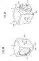
- connection element 2 of the preceding figures in a perspective view (without valve elements and thermal generators).
- connection element has a cuboid base body 21.
- the invention is of course not limited to a specific geometry of the connection element, but the shape of the connection element can in principle be chosen arbitrarily, for example, also cylindrical.
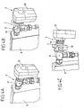
- FIGS. 4A to 4C refer to the mounting of the thermoelectric device to a radiator, wherein FIG. 4A represents a radiator 8, on which only a valve 3 is arranged for adjusting the supply amount of the heating medium in the radiator, but not a thermoelectric device according to the invention.
- the valve 3 consists of a valve top 32 which is screwed by means of a union nut 911 on a valve body 31.
- thermoelectric device 1 is now mounted so that its connection element 2 is connected both to the valve lower part 31 and to the valve upper part 32, ie the connection element 2 is arranged between these valve elements.
- connection element 2 is connected both to the valve lower part 31 and to the valve upper part 32, ie the connection element 2 is arranged between these valve elements.
- FIGS. 4B, 4C is the valve body 31 in the internal thread 211 ( Fig. 3A ) of the connecting element 2 is screwed.
- the valve upper part 32 is coupled by means of the union nut 911, which is screwed onto the external thread 213 of the connecting element 2, with the connecting element.
- FIGS. 4B, 4C On the side surfaces of the connecting element 2, which have the connecting portions 216, 217 for the thermal generators, is according to the FIGS. 4B, 4C each pre-assembled a printed circuit board 10, while the thermal generators are not yet mounted.
- the printed circuit boards 10 each have a recess in the region of the connecting regions 216, 217, so that the connecting regions, including the bores for fastening a heat sink (cf. FIG. 2B ) are accessible from the outside.
- the printed circuit boards 10 have structures which can serve as spacers between the heat sink and the connection element 2; see. FIG. 2B .
- means for processing the electrical voltage generated by the thermal generator in particular a DC booster circuit are arranged on the circuit boards.
- an electrical connection is provided, via which the conditioned voltage can be supplied to an electrical consumer.
- the upper valve part 32 has an electric motor for moving the valve tappet, which can be operated at least partially by means of the electrical energy generated by the thermal generators.
- the (prepared) thermoelectric generator voltage can be fed to the electric motor or an operating circuit for operating the electric motor via a connection on the printed circuit board 10.
- thermoelectric generator voltage is supplied via a battery compartment adapter.
- a battery compartment adapter has a matched to the dimensions of a battery compartment contact, which can be used instead of batteries (or at least one battery) in the battery compartment of the valve top to feed the electrical voltage generated by the thermal generator.
- a candidate battery compartment adapter is, as already mentioned above, in the German patent application DE 10 2010 029 090.4 described.
Landscapes
- Temperature-Responsive Valves (AREA)
- Electrically Driven Valve-Operating Means (AREA)
- Details Of Valves (AREA)
- Measuring Volume Flow (AREA)
Description
- Die Erfindung betrifft eine thermoelektrische Vorrichtung zum Erzeugen von elektrischer Energie gemäß Anspruch 1.
- Aus dem Stand der Technik sind thermoelektrische Vorrichtungen zur Umwandlung von Wärmeenergie in elektrische Energie bekannt. Beispielsweise weisen derartige Vorrichtungen Thermogeneratoren auf, die unter Einwirkung eines Temperaturgradienten gemäß dem Seebeck-Effekt eine elektrische Spannung erzeugen.
- Beispielsweise ist aus der
WO 2009/106431 A2 ein Thermogenerator bekannt, der als Baueinheit mit einem Kollektor für eine thermische Solaranlage ausgebildet ist. - Die
US 6 105 373 A offenbart eine thermoelektrische Vorrichtung mit einem thermoelektrische Schichten aufweisenden Substrat sowie Zuführmitteln, die ein Medium gegen einander gegenüberliegende Seiten des Substrats leitet. - Darüber hinaus offenbart die
EP 1 729 195 A1 einen Heizkörperventil-Thermostataufsatz mit einer Betätigungseinrichtung, die mit einem Ventilelement zusammenwirkt, einem elektrischen Verbraucher sowie einer elektrischen Energieversorgungseinrichtung in Form eines thermoelektrischen Generators. - Zudem ist aus der
GB 2 216 293 A - Das der vorliegenden Erfindung zugrunde liegende Problem besteht darin, eine thermoelektrische Vorrichtung zu schaffen, mit der auf einfache Weise thermische Energie eines Mediums in elektrische Energie umgewandelt werden kann.
- Dieses Problem wird durch die thermoelektrische Vorrichtung mit den Merkmalen gemäß Anspruch 1 gelöst. Weiterbildungen der Erfindung sind in den abhängigen Ansprüchen angegeben.
- Danach wird eine thermoelektrische Vorrichtung zum Erzeugen von elektrischer Energie bereitgestellt, mit
- einem Anschlusselement, das mit einem Ventil, welches zum Einstellen des Flusses eines Mediums dient und aus einem Ventilunterteil und einem Ventiloberteil besteht, verbindbar ist; und
- mindestens einem an dem Anschlusselement angeordneten Thermogenerator zum Umwandeln von thermischer Energie des Mediums in elektrische Energie, wobei
- das Anschlusselement erste Verbindungsmittel aufweist, über die es mit einem ersten Ventilelement in Form eines Ventilunterteils des Ventils verbindbar ist, sowie zweite Verbindungsmittel, über die es mit einem zweiten Ventilelement in Form eines Ventiloberteils des Ventils verbindbar ist, oder
- das Anschlusselement erste Verbindungsmittel aufweist, über die es mit einem ersten Ventilelement in Form eines ersten Bestandteils des Ventiloberteils verbindbar ist, sowie zweite Verbindungsmittel, über die es mit einem zweiten Ventilelement in Form eines zweiten Bestandteils des Ventiloberteils verbindbar ist.
- Bei dem Medium handelt es sich insbesondere um ein temperiertes Medium (Gas oder Flüssigkeit), z.B. um ein Heizmedium, das in einen Heizkörper einströmt. Es ist jedoch auch denkbar, dass das Medium ein Kühlmedium (z.B. einer industriellen Produktionsanlage) ist, dessen Fluss über das Ventil eingestellt wird, und das einen Temperaturgradienten am Ort des Thermogenerators erzeugt.
- Die erfindungsgemäße thermoelektrische Vorrichtung ist mittels des Anschlusselementes auf einfache Weise z.B. in ein bestehendes Heizungssystem (insbesondere in Form eines Raumheizungssystems) oder Kühlsystem integrierbar. Durch die Anordnung des Anschlusselementes zwischen den beiden Ventilelementen des Ventils befindet sich der Thermogenerator (bzw. eine Mehrzahl von Thermogeneratoren) zudem nah an dem Medium, so dass eine ausreichend effiziente Wandlung der thermischen Energie des Mediums in elektrische Energie möglich ist.
- Das Ventil, mit dem das Anschlusselement verbunden werden kann, weist ein erstes Ventilelement in Form eines Ventiloberteils sowie ein zweites Ventilelement in Form eines Ventilkörpers (Ventilunterteils) auf, wobei der Ventilkörper insbesondere mit einer Leitung, über die das Medium geleitet, z.B. einem Heizkörper zugeführt, wird, verbunden ist und einen Kanal aufweist, über den das Medium, z.B. zum Heizkörper, fließt. Das Ventiloberteil weist einen bewegbaren Ventilstößel auf, der mit einem Absperrkörper (z.B. in Form eines "Ventiltellers") des Ventilunterteils zusammenwirkt, wobei der Absperrkörper in Abhängigkeit von der Stellung des Ventilstößels den Durchströmquerschnitt des Kanals des Ventilunterteils verändert. Insbesondere wird bei einem Bewegen des Ventilstößels auf den Ventilkörper zu der Durchfluss durch den Ventilkörper reduziert oder versperrt.
- Die Bewegung des Ventilstößels kann z.B. dadurch erzeugt werden, dass das Ventiloberteil ein mit dem Ventilstößel zusammenwirkendes Ausdehnelement aufweist, das sich je nach Umgebungstemperatur mehr oder weniger stark ausdehnt und somit den Ventilstößel mehr oder weniger stark in Richtung auf das Ventilunterteil drückt. Das Ventiloberteil kann jedoch auch manuell bedienbar sein, wobei z.B. eine Drehung des Ventiloberteils eine Bewegung des Ventilstößels hervorruft. Es ist insbesondere auch möglich, dass der Ventilstößel über einen Elektromotor bewegt wird, wobei der Elektromotor z.B. über eine zentrale (d.h. separat zu dem Ventil angeordnete) Temperatursteuerung betrieben wird (insbesondere per Funk).
- Gemäß einer Ausgestaltung der Erfindung weisen die ersten Verbindungsmittel zum Verbinden des Anschlusselementes mit dem ersten Ventilelement ein Gewinde auf, über das das erste Ventilelement mit dem Anschlusselement verschraubt werden kann. Des Weiteren können auch die zweiten Verbindungsmittel ein Gewinde aufweisen, über das das Anschlusselement mit dem zweiten Ventilelement koppelbar ist. Beispielsweise handelt es sich bei dem Gewinde der ersten Verbindungsmittel um ein Innengewinde und bei dem Gewinde der zweiten Verbindungsmittel um ein Außengewinde. Allerdings müssen die Verbindungsmittel nicht zwingend in Form von Gewinden ausgebildet sein, sondern es sind auch andere Arten von Verbindungsmitteln denkbar, z.B. Rastelemente oder sonstige Strukturen, die eine form- und/oder kraftschlüssige Verbindung zu den Ventilelementen zulassen. Das Anschlusselement kann somit auf einfache Weise mit einem vorhandenen Ventil gekoppelt und somit in ein bestehendes System integriert werden ("Retro-Fit").
- Gemäß einer anderen Ausgestaltung der Erfindung weist die thermoelektrische Vorrichtung ein Übertragungselement auf, das mit einem Ventilstößel des zweiten Ventilelementes (des "Ventiloberteils") so zusammenwirken kann, dass es durch eine Bewegung des Ventilstößels in Bewegung versetzt wird und somit die Bewegung des Ventilstößels auf einen Absperrkörper des ersten Ventilelementes (des "Ventilunterteils") überträgt.
- Insbesondere weist das Ventilunterteil ein Außengewinde auf, das in ein Innengewinde der ersten Verbindungsmittel eingeschraubt und somit mit dem Anschlusselement verbunden werden kann. Das Ventiloberteil kann ein Innengewinde oder eine Überwurfmutter mit einem Innengewinde aufweisen, über das es auf ein Außengewinde der zweiten Verbindungsmittel aufgeschraubt werden kann. Das Anschlusselement wird somit zwischen dem ersten und dem zweiten Ventilelement angeordnet, wobei jedoch mittels des Übertragungselementes die Funktionalität des Ventils voll erhalten bleibt.
- Das Anschlusselement weist insbesondere einen Kanal auf, in der das Übertragungselement zumindest abschnittsweise geführt ist, so dass es im montierten Zustand der thermoelektrischen Vorrichtung (d.h. insbesondere, wenn das Anschlusselement mit dem ersten und dem zweiten Ventilelement verbunden ist) relativ zu dem Anschlusselement bewegbar ist. Insbesondere ist das Übertragungselement länglich (z.B. zylindrisch) ausgebildet, wobei es durch eine lineare Bewegung des Ventilstößels ebenfalls in eine lineare Bewegung versetzbar ist.
- Gemäß der Erfindung weist das Anschlusselement mindestens einen Verbindungsbereich zum Verbinden mit dem Thermogenerator auf, an dem der Thermogenerator mit einer Seite anliegt. Die an dem Verbindungsbereich anliegende Seite des Thermogenerators ist dessen Heißseite, über die über das Anschlusselement zum Thermogenerator geleitete Wärme zur Kaltseite des Thermogenerators (die der Heißseite abgewandt ist) gelangt. Der Verbindungsbereich ist beispielsweise in Form einer Erhebung einer Außenseite des Anschlusselementes ausgeformt.
- Um einen möglichst großen Temperaturgradienten zwischen Heiß- und Kaltseite des Thermogenerators zu erzeugen, kann an der Kaltseite des Thermogenerators eine Wärmesenke vorgesehen sein; beispielsweise in Form eines passiven oder aktiven Kühlkörpers. Insbesondere kann an der Kaltseite des Thermogenerators ein Rippenkühlkörper aus einem Metall (passive Kühlung) oder z.B. der kältere Rücklauf des Heizwassers (aktive Kühlung) angeordnet sein.
- Als Kühlkörper kann insbesondere ein Körper mit einer hohen thermischen Masse (d.h. mit einer hohen Wärmekapazität, z.B. auch ein mit Wasser befüllter Hohlkörper) vorgesehen sein. Mit einem solchen Körper könnte für einen gewissen Zeitraum ab Einwirkung der Wärmeenergie des Mediums ein erhöhter Temperaturgradient über den Thermogenerator und damit eine erhöhte Thermogeneratorspannung erzeugt werden. Insbesondere könnte die kurzzeitig erhöhte Thermogeneratorspannung ausreichen, um eine DC-Booster-Schaltung (s.u.) zum Anschwingen zu bringen.
- Das Anschlusselement selber ist insbesondere aus einem Metall (d. h. aus einem gut wärmeleitenden Material) gebildet, beispielsweise aus Aluminium. Das Material und die Struktur des Anschlusselementes sind insbesondere so beschaffen, dass Wärme von dem Medium möglichst effizient an den Thermogenerator geleitet werden kann.
- Des Weiteren kann die erfindungsgemäße thermoelektrische Vorrichtung einen Anschluss aufweisen, über den die vom Thermogenerator erzeugte elektrische Energie einem Verbraucher zugeführt werden kann. Der Anschluss (z. B. ein Stecker) ist z. B. eine in das Anschlusselement integrierte Steckkupplung oder eine von dem Thermogenerator oder einer elektronischen Schaltung zum Betrieb des Thermogenerators weg führende elektrische Leitung. Insbesondere weist die elektrische Leitung ein Kupplungselement auf, über das sie mit einem entsprechenden Kupplungselement des Ventils (insbesondere eines Ventiloberteils) verbindbar ist. Beispielsweise handelt es sich bei dem Kupplungselement der elektrischen Leitung um einen Standardstecker, der in eine Standardanschlussbuchse (die z.B. zum Anschließen eines Netzteils dient) des Ventils eingesteckt werden kann.
- Um ein Ventil, das konventionell über eine Batterie versorgt wird, mit elektrischer Energie des Thermogenerators der erfindungsgemäßen Vorrichtung versorgen zu können, ist es darüber hinaus denkbar, dass das Kupplungselement einen Batteriefachadapter aufweist (bzw. aus dem Batteriefachadapter besteht), der anstelle einer Batterie in ein Batteriefach des Ventils einsetzbar ist. Ein derartiger mit einem Thermogenerator verbundener Batteriefachadapter ist in der deutschen Patentanmeldung
DE 10 2010 029 090.4 vom 18.05.2010 beschrieben, auf die insofern hiermit ausdrücklich Bezug genommen wird. - Möglich ist natürlich auch, dass das Anschlusselement über eine spezielle Kupplung mit dem Ventil verbunden wird, d.h. das Anschlusselement weist ein proprietäres Kupplungselement auf, das mit einem entsprechenden propritären Kupplungselement des Ventils verbunden werden kann. Beispielsweise sind die propritären Kupplungselemente so gestaltet, dass mit dem mechanischen Verbinden des Anschlusselementes mit dem Ventil auch eine Verbindung der Kupplungselemente erfolgt. Denkbar ist z.B. auch, dass die Kupplung, d.h. das thermogeneratorseitige und das ventilseitige Kupplungselement, nach Montage des Anschlusselementes an dem Ventil von außen nicht sichtbar ist.
- Gemäß der Erfindung sind das Anschlusselement und das zweite Ventilteil (bei dem es sich um ein Ventiloberteil handelt) in einem gemeinsamen Gehäuse untergebracht. Das gemeinsame Gehäuse kann z.B. dadurch realisiert werden, dass das Anschlusselement ein erstes Gehäuse und das zweite Ventilteil ein zweites Gehäuse besitzen, wobei das erste und das zweite Gehäuse bei der Montage des Anschlusselementes an dem zweiten Ventilteil miteinander verbunden werden, z.B. über entsprechende Raststrukturen. Der elektrische Kontakt zwischen dem Thermogenerator des Anschlusselementes und dem zweiten Ventilteil wird z.B. über die erwähnten propritären Kupplungselemente hergestellt.
- Denkbar ist auch, dass sowohl das erste als auch das zweite Ventilteil, zwischen denen das Anschlusselement eingesetzt werden soll, jeweils ein Bestandteil eines Ventiloberteils sind, wobei beispielsweise das erste Ventilteil Mittel zum Verbinden mit einem Ventilunterteil aufweist. Beispielsweise weist das erste Ventilteil ein erstes Gehäuseteil und das zweite Ventilteil ein zweites Gehäuseteil auf, wobei das erste und das zweite Gehäuseteil miteinander (z.B. lösbar) verbunden werden können, um ein gemeinsames Gehäuse des Ventiloberteils zu realisieren. Möglich ist, dass das Anschlusselement in das Gehäuseteil des ersten oder zweiten Ventilteils integrierbar ist, so dass es sich nach einem Verbinden der beiden Gehäuseteile im Innern des gebildeten gemeinsamen Gehäuses befindet. Denkbar ist auch, dass das Anschlusselement ebenfalls ein Gehäuseteil aufweist, das mit dem jeweiligen Gehäuseteil des ersten und des zweiten Ventilteils verbindbar ist, z.B. per Rastverbindung.
- Der Verbraucher, der über den Anschluss des Anschlusselementes mit dem Thermogenerator verbunden ist, ist z. B. eine Komponente des mit dem Anschlusselement gekoppelten Ventils (d.h. insbesondere eine Komponente eines der beiden Ventilelemente) selber. Beispielsweise weist das zweite Ventilelement einen Elektromotor auf, der mit der elektrischen Energie des Thermogenerators versorgt wird. Des Weiteren ist denkbar, dass das Ventil funkgesteuert ist und Funkkomponenten des Ventils oder einer Ventilsteuerung mit der Thermogeneratorenergie gespeist werden. Möglich ist auch, dass zusätzlich oder alternativ zu dem Ventil andere Komponenten eines Heizungssystems über die Thermogeneratorspannung versorgt werden.
- Beispielsweise könnte eine Vorrichtung zur Ermittlung des Energieverbrauchs ("Heizkostenverteiler") in der Nähe der thermoelektrischen Vorrichtung angebracht werden, um sie mit der Thermogeneratorspannung versorgen zu können. Hier ist denkbar, dass das Modell, über das aus den Messdaten des Heizkostenverteilers (i.a. die verdunstete Menge einer Flüssigkeit) auf den Verbrauch geschlossen wird, an diese Position des Heizkostenverteilers angepasst wird.
- Es ist auch denkbar, dass der an dem Anschlusselement angeordnete Thermogenerator (insbesondere in Kombination mit einem Kühlkörper) als Heizkostenverteiler genutzt wird. Hierzu werden insbesondere die Temperaturen an der Heiß- und der Kaltseite des Thermogenerators ermittelt und in Abhängigkeit von diesen Temperaturen und dem thermischen Widerstand des Kühlkörpers und des Thermogenerators sowie des Heizungstyps (z.B. dessen Abmessungen) der Energieverbrauch bestimmt. Darüber hinaus kann das Anschlusselement eine Regelungselektronik aufweisen oder mit einer solchen verbunden sein, die in Abhängigkeit von dem ermittelten Momentanverbrauch das Ventil steuert; z.B. bei einem Thermostatkopf, dessen Stellelement per Elektromotor betrieben wird, ein Steuersignal an den Elektromotor übermittelt.
- Darüber hinaus kann die thermoelektrische Vorrichtung auch Mittel zum Speichern der vom Thermogenerator erzeugten elektrischen Energie aufweisen, z. B. in Form einer elektrischen Schaltung und/oder eines Kondensators. Beispielsweise sind die Mittel zum Speichern der elektrischen Energie in das Anschlusselement integriert oder an dem Anschlusselement angeordnet.
- Es ist auch denkbar, dass die thermoelektrische Vorrichtung Mittel zum Konvertieren der vom Thermogenerator erzeugten elektrischen Spannung aufweist, die z. B. ebenfalls an dem Anschlusselement angeordnet sein können. Die Mittel zum Konvertieren der Thermogeneratorspannung umfassen z. B. eine DC-Booster-Schaltung (Gleichspannungserhöhungsschaltung) zum Erhöhen der vom Thermogenerator erzeugten Spannung. Die DC-Booster-Schaltung ist z. B. in Form eines elektronischen Schaltkreises realisiert, der insbesondere ebenfalls an dem Anschlusselement angeordnet oder in das Anschlusselement integriert ist. Beispielsweise ist die DC-Booster-Schaltung zusammen mit den erwähnten Mitteln zum Speichern der Thermogeneratorenergie auf einer Leiterplatte angeordnet.
- Die Erfindung betrifft auch ein Heiz- oder Kühlsystem mit der erfindungsgemäßen thermoelektrischen Vorrichtung.
- Die Erfindung wird im Folgenden anhand von Ausführungsbeispielen unter Bezugnahme auf die Figuren näher erläutert. Es zeigen:
- Fig. 1A und 1B
- Ansichten einer thermoelektrischen Vorrichtung gemäß einem Ausführungsbeispiel der Erfindung vor Montage der Thermogeneratoren an dem Anschlusselement;
- Fig. 2A und 2B
- die thermoelektrische Vorrichtung aus den
Figuren 1A und 1B nach Montage der Thermogeneratoren; - Fig. 3A und 3B
- das Anschlusselement der thermoelektrischen Vorrichtung aus den
Figuren 1A und 1B in perspektivischer Darstellung; und - Fig. 4A bis 4C
- Ansichten der an einem Heizungsventil montierten thermoelektrischen Vorrichtung aus den
Figuren 2A und 2B . - Die
Figuren 1A und 1B zeigen die thermoelektrische Vorrichtung 1 in Seitenansicht (Figur 1 A) bzw. in Vorderansicht (Figur 1 B) . Die dargestellte thermoelektrische Vorrichtung 1 umfasst ein Anschlusselement 2, das nach Art eines Adapters mit einem Ventil, das zum Einstellen eines Flusses eines Heizmediums in einen Heizkörper (nicht dargestellt) dient, verbunden werden kann. Das Ventil weist ein erstes Vertilelement in Form eines Ventilunterteils 31 sowie ein zweites Ventilelement in Form eines Ventiloberteils (nicht dargestellt) auf. - Das Anschlusselement 2 umfasst einen zumindest näherungsweise quaderförmigen Grundkörper 21, der an einer Stirnseite 2100 eine Bohrung 2101 mit einem Innengewinde 211 (beispielsweise ein M30-Gewinde) aufweist, in das das Ventilunterteil 31 eingeschraubt ist. An einer der Stirnseite 2100 gegenüberliegenden Stirnseite 2200 des Grundkörpers 21 befindet sich ein zylindrischer Ansatz 212 mit einem Außengewinde 213 (z.B. ebenfalls ein M30-Gewinde), das zur Kopplung des Anschlusselementes 2 mit dem Ventiloberteil dient; vgl. die
Figuren 4B und 4C . - An zwei einander gegenüberliegenden und senkrecht zu den Stirnseiten 2100 und 2200 orientierten Seitenflächen 214, 215 des Grundkörpers 21 ist jeweils ein als Erhebung (mit rechteckiger Kontur) der Seitenflächen 214, 215 ausgeformter Verbindungsbereich 216, 217 vorgesehen, über den ein Thermogenerator (in Figuren 1A und 1B nicht dargestellt) mit dem Grundkörper 21 des Anschlusselementes 2 verbunden werden kann. Die Verbindungsbereiche 216, 217 weisen darüber hinaus Bohrungen 2161 mit einem Innengewinde auf, über die eine Wärmesenke (vgl.
Figuren 2A, 2B ) mit dem Grundkörper 21 des Anschlusselementes 2 verbunden werden kann. - Des Weiteren weist das Anschlusselement 2 einen Kanal in Form einer Durchgangsbohrung 4 auf, die sich parallel zu den Seitenflächen 214, 215 und zwischen den Stirnseiten 2100 und 2200 erstreckt. Über die Stirnseite 2100 ragt ein stiftartiges Teilstück 311 eines Absperrkörpers zum Einstellen des Querschnitts eines in dem Ventilunterteil ausgebildeten Kanals, durch den das Heizmedium strömt, in die Durchgangsbohrung 4 hinein. Im Inneren der Durchgangsbohrung 4 befindet sich ein Übertragungselement in Form eines Übertragungsstiftes 5.
- Der Übertragungsstift 5 wirkt so mit einem Ventilstößel (nicht dargestellt) eines über das Gewinde 214 mit dem Anschlusselement 2 gekoppelten Ventiloberteils zusammen, dass bei einer Bewegung des Ventilstößels auf das Ventilunterteil 31 zu dieses gegen den Stift 311 drückt, wodurch der Absperrkörper des Ventilunterteils 31 den Durchströmquerschnitt des Ventilunterteils reduziert oder ganz verschließt. Umgekehrt wird der Stift 311 (insbesondere über eine Feder) unter Vorspannung gehalten, so dass eine Bewegung des Ventilstößels von dem Ventilunterteil 31 weg ein Nachfolgen des Übertragungsstiftes 5 und des Stiftes 311 und somit eine Vergrößerung oder vollständige Öffnung des Durchströmquerschnitt des Ventilunterteils bewirkt. Somit wird eine Bewegung des Ventilstößels bei Zwischenschalten des Anschlusselementes 5 zwischen das Ventilunter- und das Ventiloberteil nicht mehr unmittelbar auf den Absperrkörper des Ventilkörpers übertragen, sondern über eine Bewegung des Übertragungsstiftes 5.
- Die
Figuren 2A und 2B zeigen die Anordnung derFiguren 1A und 1B , wobei an den Verbindungsbereichen 216, 217 jeweils ein Thermogenerator 6a, 6b angeordnet ist. Bei den Thermogeneratoren 6a, 6b handelt es sich um mikrotechnologisch hergestellte Thermogeneratoren, die jeweils mit ihrer Heißseite mit einer Außenseite des Grundkörpers 21 (d.h. mit einer Außenseite der Verbindungsbereiche 216, 217) des Anschlusselementes 2 verbunden sind. Die Kaltseite der Thermogeneratoren 6a, 6b ist jeweils mit einer Wärmesenke in Form eines großflächigen Rippenkühlkörpers 7a, 7b verbunden, um eine möglichst gute Wärmeabfuhr von der Kaltseite der Thermogeneratoren 6a, 6b und damit einen möglichst großen Temperaturgradienten über den jeweiligen Thermogenerator 6a, 6b zu erzeugen. Die Kühlkörper 7a, 7b sind über (insbesondere hohlzylindrische) Abstandselemente 71 mit dem Anschlusselement verbunden (insbesondere über die in denFig. 1A und 1B gezeigten Bohrungen 2161). - Die Thermogeneratoren 6a, 6b werden durch Verschrauben des jeweiligen Kühlkörpers 7a, 7b mit dem Anschlusselement 2 gegen den Verbindungsbereich 216, 217 gepresst und dadurch einerseits mit den Kühlkörpern 7a, 7b und andererseits mit dem Verbindungsbereich 216, 217 des Anschlusselementes 2 verbunden und thermisch gekoppelt. Zwischen der Kaltseite der Thermogeneratoren 6a, 6b und dem Kühlkörper 7a, 7b sowie zwischen der Heißseite der Thermogeneratoren und dem Verbindungsbereich 216, 217 ist jeweils ein gut wärmeleitendes Interface-Material (Grenzschichtmaterial), z.B. in Form einer gut wärmeleitenden Folie, insbesondere einer Graphitfolie, angeordnet, um einen möglichst guten Wärmeübergang von den Thermogeneratoren zum Kühlkörper bzw. zum Anschlusselement 2 zu schaffen.
- Die
Figuren 3A und 3B zeigen das aus einem Stück hergestellte Anschlusselement 2 der vorhergehenden Figuren in perspektivischer Darstellung (ohne Ventilelemente und Thermogeneratoren). Es wird darauf hingewiesen, dass das Anschlusselement zwar einen quaderförmigen Grundkörper 21 aufweist. Die Erfindung ist jedoch selbstverständlich nicht auf eine bestimmte Geometrie des Anschlusselementes limitiert, sondern die Form des Anschlusselementes kann im Prinzip beliebig gewählt werden, z.B. auch zylindrisch. - Die
Figuren 4A bis 4C beziehen sich auf die Montage der thermoelektrischen Vorrichtung an einem Heizkörper, wobeiFigur 4A einen Heizkörper 8 darstellt, an dem lediglich ein Ventil 3 zum Einstellen der Zulaufmenge des Heizmediums in den Heizkörpers angeordnet ist, jedoch noch keine thermoelektrische Vorrichtung gemäß der Erfindung. Das Ventil 3 besteht aus einem Ventiloberteil 32, das mit Hilfe einer Überwurfmutter 911 auf ein Ventilunterteil 31 aufgeschraubt ist. - Die erfindungsgemäße thermoelektrische Vorrichtung 1 wird nun so montiert, dass ihr Anschlusselement 2 sowohl mit dem Ventilunterteil 31 als auch mit dem Ventiloberteil 32 verbunden wird, d.h. das Anschlusselement 2 wird zwischen diesen Ventilelementen angeordnet. Gemäß den
Figuren 4B, 4C ist das Ventilunterteil 31 in das Innengewinde 211 (Fig. 3A ) des Anschlusselementes 2 eingeschraubt. Auf der dem Innengewinde 211 abgewandten Seite des Anschlusselementes 2 ist das Ventiloberteil 32 mittels der Überwurfmutter 911, die auf das Außengewinde 213 des Anschlusselementes 2 aufgeschraubt ist, mit dem Anschlusselement gekoppelt. - An den Seitenflächen des Anschlusselementes 2, die die Verbindungsbereiche 216, 217 für die Thermogeneratoren aufweisen, ist gemäß den
Figuren 4B, 4C jeweils eine Leiterplatte 10 vormontiert, während die Thermogeneratoren noch nicht montiert sind. Die Leiterplatten 10 weisen jeweils eine Aussparung im Bereich der Verbindungsbereiche 216, 217 auf, so dass die Verbindungsbereiche einschließlich der Bohrungen zum Befestigen eines Kühlkörpers (vergleicheFigur 2B ) von außen zugänglich sind. - Die Leiterplatten 10 weisen insbesondere Strukturen auf, die als Abstandshalter zwischen dem Kühlkörper und dem Anschlusselement 2 dienen können; vgl.
Figur 2B . Darüber hinaus sind auf den Leiterplatten jeweils z.B. Mittel zur Aufbereitung der vom Thermogenerator jeweils erzeugten elektrischen Spannung, insbesondere einer DC-Booster-Schaltung angeordnet. Des Weiteren ist ein elektrischer Anschluss vorgesehen, über den die aufbereitete Spannung einem elektrischen Verbraucher zugeführt werden kann. - Vorliegend weist das Ventiloberteil 32 einen Elektromotor zum Bewegen des Ventilstößels auf, der zumindest teilweise mittels der von den Thermogeneratoren erzeugten elektrischen Energie betrieben werden kann. Hierzu kann über einen Anschluss auf der Leiterplatte 10 die (aufbereitete) Thermogeneratorspannung dem Elektromotor bzw. einer Betriebschaltung zum Betreiben des Elektromotors zugeführt werden.
- Für den Fall, dass der Elektromotor des Ventiloberteils über eine oder mehrere in dem Ventiloberteil angeordnete Batterie(n) betrieben wird, ist auch denkbar, dass die Thermogeneratorspannung über einen Batteriefachadapter zugeführt wird. Ein derartiger Batteriefachadapter weist einen an die Abmessungen eines Batteriefachs angepassten Kontakt auf, der anstelle von Batterien (bzw. zumindest einer Batterie) in das Batteriefach des Ventiloberteils eingesetzt werden kann, um die vom Thermogenerator erzeugte elektrische Spannung einzuspeisen. Ein in Frage kommender Batteriefachadapter ist, wie bereits oben erwähnt, in der deutschen Patentanmeldung
DE 10 2010 029 090.4 beschrieben. -
- 1
- thermoelektrische Vorrichtung
- 2
- Anschlusselement
- 3
- Ventil
- 4
- Durchgangsbohrung
- 5
- Übertragungsstift
- 6a, 6b
- Thermoelement
- 7a, 7b
- Kühlkörper
- 8
- Heizkörper
- 10
- Leiterplatte
- 21
- Grundkörper
- 31
- Ventilunterteil
- 32
- Ventiloberteil
- 71
- Abstandselement
- 211
- Innengewinde
- 212
- Ansatz
- 213
- Außengewinde
- 214, 215
- Seitenfläche
- 216, 217
- Verbindungsbereich
- 311
- Stift
- 911
- Überwurfmutter
- 2100,2200
- Stirnseite
- 2101
- Bohrung
Claims (13)
- Thermoelektrische Vorrichtung zum Erzeugen von elektrischer Energie, mit- einem Anschlusselement (2), das mit einem Ventil (3), welches zum Einstellen des Flusses eines Mediums dient und aus einem Ventilunterteil (31) und einem Ventiloberteil (32) besteht, verbindbar ist; und- mindestens einem an dem Anschlusselement (2) angeordneten Thermogenerator (6a, 6b) zum Umwandeln von thermischer Energie des Mediums in elektrische Energie, wobei das Anschlusselement (2) mindestens einen Verbindungsbereich (216, 217) aufweist, an dem der Thermogenerator (6a, 6b) mit einer Seite anliegt,dadurch gekennzeichnet, dass
das Anschlusselement (2) erste Verbindungsmittel (211) aufweist, über die es mit einem ersten Ventilelement (31) in Form des Ventilunterteils des Ventils (3) verbindbar ist, sowie zweite Verbindungsmittel (213), über die es mit einem zweiten Ventilelement (32) in Form des Ventiloberteils des Ventils (3) verbindbar ist, wobei das Anschlusselement (2) ein erstes Gehäuse und das Ventiloberteil ein zweites Gehäuse besitzen, wobei das erste und das zweite Gehäuse zur Realisierung eines gemeinsamen Gehäuses bei der Montage des Anschlusselements (2) an dem Ventiloberteil miteinander verbunden werden, oder
das Anschlusselement (2) erste Verbindungsmittel (211) aufweist, über die es mit einem ersten Ventilelement (31) in Form eines ersten Bestandteils des Ventiloberteils verbindbar ist, sowie zweite Verbindungsmittel (213), über die es mit einem zweiten Ventilelement (32) in Form eines zweiten Bestandteils des Ventiloberteils verbindbar ist. - Thermoelektrische Vorrichtung nach Anspruch 1, dadurch gekennzeichnet, dass die ersten Verbindungsmittel (211) ein erstes Gewinde aufweisen, über das das erste Ventilelement (31) mit dem Anschlusselement (2) gekoppelt werden kann, und die zweiten Verbindungsmittel (213) ein zweites Gewinde, über das das Anschlusselement (2) mit dem zweiten Ventilelement (32) gekoppelt werden kann.
- Thermoelektrische Vorrichtung nach einem der vorhergehenden Ansprüche, gekennzeichnet durch ein Übertragungselement (5), das mit einem Ventilstößel des zweiten Ventilelements (32) so zusammenwirken kann, dass es durch eine Bewegung des Ventilstößels in Bewegung versetzt wird und die Bewegung des Ventilstößels auf einen Absperrkörper des ersten Ventilelementes (31) überträgt.
- Thermoelektrische Vorrichtung nach Anspruch 3, dadurch gekennzeichnet, dass das Übertragungselement (5) in einem Kanal (4) des Anschlusselementes (2) zumindest abschnittsweise so geführt ist, dass es nach Kopplung des Anschlusselementes (2) mit dem zweiten Ventilelement (32) relativ zu dem Anschlusselement (2) bewegbar ist.
- Thermoelektrische Vorrichtung nach einem der vorhergehenden Ansprüche, dadurch gekennzeichnet, dass der Verbindungsbereich (216, 217) als Erhebung einer Außenseite des Anschlusselementes (2) ausgebildet ist
- Thermoelektrische Vorrichtung nach einem der vorhergehenden Ansprüche, gekennzeichnet durch eine Wärmesenke (7a, 7b), die mit einer dem Anschlusselement (2) abgewandten Seite des Thermogenerators (6a, 6b) in thermischem Kontakt steht.
- Thermoelektrische Vorrichtung nach Anspruch 6, dadurch gekennzeichnet, dass die Wärmesenke (7a, 7b) an dem Anschlusselement (2) festgelegt ist.
- Thermoelektrische Vorrichtung nach einem der vorhergehenden Ansprüche, dadurch gekennzeichnet, dass das Anschlusselement (2) aus einem Metall, insbesondere aus Aluminium, einer Legierung und/oder einem Composite-Material gebildet ist.
- Thermoelektrische Vorrichtung nach einem der vorhergehenden Ansprüche, gekennzeichnet durch einen Anschluss, über den die von dem Thermogenerator (6a, 6b) erzeugte elektrische Energie einem Verbraucher zugeführt werden kann.
- Thermoelektrische Vorrichtung nach einem der vorhergehenden Ansprüche, gekennzeichnet durch eine mit dem Thermogenerator (6a, 6b) elektrisch verbundene elektrische Leitung, die ein Kupplungselement aufweist, über das sie mit einem entsprechenden Kupplungselement des Ventils (3) verbindbar ist.
- Thermoelektrische Vorrichtung nach Anspruch 10, dadurch gekennzeichnet, dass das Kupplungselement einen Batteriefachadapter aufweist, der anstelle einer Batterie in ein Batteriefach des Ventils (3) einsetzbar ist.
- Thermoelektrische Vorrichtung nach einem der vorhergehenden Ansprüche, gekennzeichnet durch Mittel zum Speichern der von dem Thermogenerator (6a, 6b) erzeugten elektrischen Energie.
- Thermoelektrische Vorrichtung nach einem der vorhergehenden Ansprüche, gekennzeichnet durch Mittel zum Konvertieren der vom Thermogenerator (6a, 6b) erzeugten elektrischen Spannung, insbesondere in Form einer DC-Booster-Schaltung zum Erhöhen der vom Thermogenerator (6a, 6b) erzeugten Spannung.
Applications Claiming Priority (1)
| Application Number | Priority Date | Filing Date | Title |
|---|---|---|---|
| DE102010040107A DE102010040107B4 (de) | 2010-09-01 | 2010-09-01 | Thermoelektrische Vorrichtung zum Erzeugen von elektrischer Energie |
Publications (4)
| Publication Number | Publication Date |
|---|---|
| EP2426569A2 EP2426569A2 (de) | 2012-03-07 |
| EP2426569A3 EP2426569A3 (de) | 2013-02-20 |
| EP2426569B1 EP2426569B1 (de) | 2015-03-18 |
| EP2426569B2 true EP2426569B2 (de) | 2019-03-13 |
Family
ID=44772743
Family Applications (1)
| Application Number | Title | Priority Date | Filing Date |
|---|---|---|---|
| EP11179732.0A Active EP2426569B2 (de) | 2010-09-01 | 2011-09-01 | Thermoelektrische Vorrichtung zum Erzeugen von elektrischer Energie |
Country Status (3)
| Country | Link |
|---|---|
| EP (1) | EP2426569B2 (de) |
| DE (1) | DE102010040107B4 (de) |
| DK (1) | DK2426569T3 (de) |
Families Citing this family (3)
| Publication number | Priority date | Publication date | Assignee | Title |
|---|---|---|---|---|
| DE102012102613A1 (de) * | 2012-03-27 | 2013-10-02 | Minebea Co., Ltd. | Thermoelektrischer Energiewandler |
| DE102015205638A1 (de) * | 2014-08-28 | 2016-03-03 | Micropatent B. V. | Stellantriebsanordnungen für Ventile und Verfahren zum Betreiben von Stellan- triebsanordnungen |
| DE102017113149A1 (de) * | 2017-06-14 | 2018-12-20 | Minebea Mitsumi Inc. | Aktorsystem mit einem Energiewandler und einem Aktuator |
Citations (4)
| Publication number | Priority date | Publication date | Assignee | Title |
|---|---|---|---|---|
| DE3020835C2 (de) † | 1980-06-02 | 1986-08-07 | Dieter Gräßlin Feinwerktechnik, 7742 St Georgen | Schaltuhrgesteuertes Thermostatventil |
| DE3153654C2 (en) † | 1981-09-10 | 1990-09-06 | Theodor Heimeier Metallwerk Kg, 4782 Erwitte, De | Central heating system with individually controlled radiators |
| DE10065098B4 (de) † | 2000-12-28 | 2004-01-22 | F.W. Oventrop Gmbh & Co. Kg | Einstellvorrichtung für Ventile |
| DE102006006999B3 (de) † | 2006-02-15 | 2007-02-08 | Theodor Heimeier Metallwerk Gmbh | Thermostatventil für Heiz- und/oder Kühlkörper |
Family Cites Families (7)
| Publication number | Priority date | Publication date | Assignee | Title |
|---|---|---|---|---|
| DE3405774A1 (de) * | 1984-02-17 | 1985-08-22 | Heinz Buchs Lampert | Vorrichtung zum gemeinsamen steuern eines fluidstromes und messen eines dem fluidstrom und einer zweiten groesse proportionalen wertes |
| DE3414481A1 (de) * | 1984-04-17 | 1985-10-24 | Hans Grohe Gmbh & Co Kg, 7622 Schiltach | Vorrichtung zur steuerung des durchflusses einer fluessigkeit |
| GB2216293B (en) * | 1988-03-01 | 1992-02-19 | David Philip Reynolds | Valves |
| JPH1084139A (ja) * | 1996-09-09 | 1998-03-31 | Technova:Kk | 熱電変換装置 |
| DE102005025501C5 (de) * | 2005-06-03 | 2010-10-21 | Danfoss A/S | Wärmetauscherventil-Steueraufsatz, insbesondere Heizkörperventil-Thermostataufsatz |
| DE102008011984B4 (de) * | 2008-02-29 | 2010-03-18 | O-Flexx Technologies Gmbh | Thermogenerator und thermische Solaranlage mit Thermogenerator |
| DE102010029090A1 (de) | 2010-05-18 | 2011-11-24 | Micropelt Gmbh | Thermogeneratoranordnung und Verfahren zum Herstellen einer Thermogeneratoranordnung |
-
2010
- 2010-09-01 DE DE102010040107A patent/DE102010040107B4/de active Active
-
2011
- 2011-09-01 DK DK11179732.0T patent/DK2426569T3/da active
- 2011-09-01 EP EP11179732.0A patent/EP2426569B2/de active Active
Patent Citations (4)
| Publication number | Priority date | Publication date | Assignee | Title |
|---|---|---|---|---|
| DE3020835C2 (de) † | 1980-06-02 | 1986-08-07 | Dieter Gräßlin Feinwerktechnik, 7742 St Georgen | Schaltuhrgesteuertes Thermostatventil |
| DE3153654C2 (en) † | 1981-09-10 | 1990-09-06 | Theodor Heimeier Metallwerk Kg, 4782 Erwitte, De | Central heating system with individually controlled radiators |
| DE10065098B4 (de) † | 2000-12-28 | 2004-01-22 | F.W. Oventrop Gmbh & Co. Kg | Einstellvorrichtung für Ventile |
| DE102006006999B3 (de) † | 2006-02-15 | 2007-02-08 | Theodor Heimeier Metallwerk Gmbh | Thermostatventil für Heiz- und/oder Kühlkörper |
Also Published As
| Publication number | Publication date |
|---|---|
| EP2426569A3 (de) | 2013-02-20 |
| DE102010040107B4 (de) | 2013-05-16 |
| EP2426569B1 (de) | 2015-03-18 |
| DE102010040107A8 (de) | 2012-05-10 |
| DE102010040107A1 (de) | 2012-03-01 |
| DK2426569T3 (da) | 2014-09-01 |
| EP2426569A2 (de) | 2012-03-07 |
Similar Documents
| Publication | Publication Date | Title |
|---|---|---|
| EP1729195B2 (de) | Wärmetauscherventil-Steueraufsatz, insbesondere Heizkörperventil-Thermostataufsatz, mit thermoelektrischem Generator | |
| DE102011112290B4 (de) | Aktor mit wenigstens einem, thermisches Wandlermaterial aufweisenden Stellelement | |
| DE69811739T2 (de) | Thermoelektrische kühlvorrichtung mit dynamischem schalten für die isolierung von wärmetransport | |
| DE102007017461A1 (de) | Modul zur Energieversorgung | |
| EP2426569B1 (de) | Thermoelektrische Vorrichtung zum Erzeugen von elektrischer Energie | |
| EP1926928B1 (de) | Anordnung zum verstellen eines ventils | |
| WO2012131007A2 (de) | Thermoelektrische anordnung und verfahren zum herstellen einer thermoelektrischen anordnung | |
| DE102012011962B4 (de) | Ventilaufsatz für ein Heizkörperregelventil mit elektronischem Motor und Feder sowie mit oder ohne Ausdehnungskörper | |
| DE202019005451U1 (de) | Thermoelektrisches Modul | |
| EP2222150B1 (de) | Leiterplatte mit Kühlkörper | |
| DE102016206507A1 (de) | Thermoelektrisches Modul | |
| WO2016087250A1 (de) | Kühlvorrichtung zur kühlung eines elektrischen geräts | |
| CH707391A2 (de) | Thermoelektrischer Konverter. | |
| DE102023103238B4 (de) | Vorrichtung und Verfahren zur Thermalkontrolle und Raumfahrtobjekt | |
| WO2007012402A1 (de) | Ventilanordnung und kühlvorrichtung | |
| DE102013204166A1 (de) | Thermoelektrischer Energiewandler | |
| DE102013215929A1 (de) | Batteriemodul und Verfahren zum Betreiben eines Batteriemoduls | |
| EP2690519A2 (de) | Energieautarkes Heizkörperregelventil mit linearem Piezo-Motor | |
| DE102008031584B4 (de) | Anordnung zum Verstellen eines Ventils | |
| EP4204696B1 (de) | Schraube | |
| DE102016206506A1 (de) | Thermoelektrisches Modul | |
| EP2570881A2 (de) | Temperaturregelvorrichtung, insbesondere Thermostatvorrichtung | |
| DE102016208070A1 (de) | Thermoelektrisches Modul | |
| DE102007038300A1 (de) | Aufsatz für ein Ventil | |
| EP1635238B1 (de) | Anordnung zum Verstellen eines Ventils |
Legal Events
| Date | Code | Title | Description |
|---|---|---|---|
| AK | Designated contracting states |
Kind code of ref document: A2 Designated state(s): AL AT BE BG CH CY CZ DE DK EE ES FI FR GB GR HR HU IE IS IT LI LT LU LV MC MK MT NL NO PL PT RO RS SE SI SK SM TR |
|
| AX | Request for extension of the european patent |
Extension state: BA ME |
|
| PUAI | Public reference made under article 153(3) epc to a published international application that has entered the european phase |
Free format text: ORIGINAL CODE: 0009012 |
|
| PUAL | Search report despatched |
Free format text: ORIGINAL CODE: 0009013 |
|
| AK | Designated contracting states |
Kind code of ref document: A3 Designated state(s): AL AT BE BG CH CY CZ DE DK EE ES FI FR GB GR HR HU IE IS IT LI LT LU LV MC MK MT NL NO PL PT RO RS SE SI SK SM TR |
|
| AX | Request for extension of the european patent |
Extension state: BA ME |
|
| RIC1 | Information provided on ipc code assigned before grant |
Ipc: H01L 35/32 20060101ALI20130114BHEP Ipc: G05D 23/19 20060101AFI20130114BHEP Ipc: H01L 35/30 20060101ALI20130114BHEP |
|
| 17P | Request for examination filed |
Effective date: 20130820 |
|
| RBV | Designated contracting states (corrected) |
Designated state(s): AL AT BE BG CH CY CZ DE DK EE ES FI FR GB GR HR HU IE IS IT LI LT LU LV MC MK MT NL NO PL PT RO RS SE SI SK SM TR |
|
| GRAP | Despatch of communication of intention to grant a patent |
Free format text: ORIGINAL CODE: EPIDOSNIGR1 |
|
| INTG | Intention to grant announced |
Effective date: 20131204 |
|
| GRAS | Grant fee paid |
Free format text: ORIGINAL CODE: EPIDOSNIGR3 |
|
| GRAA | (expected) grant |
Free format text: ORIGINAL CODE: 0009210 |
|
| AK | Designated contracting states |
Kind code of ref document: B1 Designated state(s): AL AT BE BG CH CY CZ DE DK EE ES FI FR GB GR HR HU IE IS IT LI LT LU LV MC MK MT NL NO PL PT RO RS SE SI SK SM TR |
|
| REG | Reference to a national code |
Ref country code: GB Ref legal event code: FG4D Free format text: NOT ENGLISH |
|
| REG | Reference to a national code |
Ref country code: CH Ref legal event code: EP |
|
| REG | Reference to a national code |
Ref country code: AT Ref legal event code: REF Ref document number: 669905 Country of ref document: AT Kind code of ref document: T Effective date: 20140615 |
|
| REG | Reference to a national code |
Ref country code: IE Ref legal event code: FG4D Free format text: LANGUAGE OF EP DOCUMENT: GERMAN |
|
| REG | Reference to a national code |
Ref country code: DE Ref legal event code: R096 Ref document number: 502011003183 Country of ref document: DE Effective date: 20140710 |
|
| REG | Reference to a national code |
Ref country code: CH Ref legal event code: PFA Owner name: MICROPELT ABWICKLUNGSGESELLSCHAFT GMBH, DE Free format text: FORMER OWNER: MICROPELT GMBH, DE Ref country code: CH Ref legal event code: PUE Owner name: MICROPATENT B.V., NL Free format text: FORMER OWNER: MICROPELT ABWICKLUNGSGESELLSCHAFT GMBH, DE Ref country code: CH Ref legal event code: NV Representative=s name: SCHMAUDER AND PARTNER AG PATENT- UND MARKENANW, CH |
|
| REG | Reference to a national code |
Ref country code: DK Ref legal event code: T3 Effective date: 20140825 |
|
| REG | Reference to a national code |
Ref country code: NL Ref legal event code: T3 |
|
| PUAC | Information related to the publication of a b1 document modified or deleted |
Free format text: ORIGINAL CODE: 0009299EPPU |
|
| REG | Reference to a national code |
Ref country code: LT Ref legal event code: MG4D |
|
| REG | Reference to a national code |
Ref country code: CH Ref legal event code: PK Free format text: DIE ERTEILUNG WURDE VOM EPA WIDERRUFEN. |
|
| 29U | Proceedings interrupted after grant according to rule 142 epc |
Effective date: 20140401 |
|
| DB1 | Publication of patent cancelled |
Effective date: 20141017 |
|
| 29W | Proceedings resumed after grant [after interruption of proceedings according to rule 142 epc] |
Effective date: 20150202 |
|
| REG | Reference to a national code |
Ref country code: NL Ref legal event code: GRER Effective date: 20141119 |
|
| GRAA | (expected) grant |
Free format text: ORIGINAL CODE: 0009210 |
|
| RAP2 | Party data changed (patent owner data changed or rights of a patent transferred) |
Owner name: MICROPATENT B.V. |
|
| AK | Designated contracting states |
Kind code of ref document: B1 Designated state(s): AL AT BE BG CH CY CZ DE DK EE ES FI FR GB GR HR HU IE IS IT LI LT LU LV MC MK MT NL NO PL PT RO RS SE SI SK SM TR |
|
| REG | Reference to a national code |
Ref country code: CH Ref legal event code: PK Free format text: DIE ERTEILUNG VOM 21.05.2014 WURDE VOM EPA WIDERRUFEN Ref country code: CH Ref legal event code: EP Ref country code: CH Ref legal event code: NV Representative=s name: SCHMAUDER AND PARTNER AG PATENT- UND MARKENANW, CH |
|
| REG | Reference to a national code |
Ref country code: DE Ref legal event code: R082 Ref document number: 502011003183 Country of ref document: DE Representative=s name: MAIKOWSKI & NINNEMANN PATENTANWAELTE, DE Ref country code: DE Ref legal event code: R082 Ref document number: 502011003183 Country of ref document: DE Representative=s name: MAIKOWSKI & NINNEMANN PATENTANWAELTE PARTNERSC, DE |
|
| REG | Reference to a national code |
Ref country code: DE Ref legal event code: R107 Ref document number: 502011003183 Country of ref document: DE Effective date: 20150507 |
|
| REG | Reference to a national code |
Ref country code: NL Ref legal event code: T3 |
|
| REG | Reference to a national code |
Ref country code: GB Ref legal event code: 732E Free format text: REGISTERED BETWEEN 20150423 AND 20150430 |
|
| REG | Reference to a national code |
Ref country code: DE Ref legal event code: R096 Ref document number: 502011003183 Country of ref document: DE Effective date: 20150603 |
|
| REG | Reference to a national code |
Ref country code: AT Ref legal event code: REF Ref document number: 669905 Country of ref document: AT Kind code of ref document: T Effective date: 20150615 |
|
| REG | Reference to a national code |
Ref country code: IE Ref legal event code: MM4A |
|
| REG | Reference to a national code |
Ref country code: LT Ref legal event code: MG4D |
|
| REG | Reference to a national code |
Ref country code: FR Ref legal event code: PLFP Year of fee payment: 5 |
|
| REG | Reference to a national code |
Ref country code: DE Ref legal event code: R026 Ref document number: 502011003183 Country of ref document: DE |
|
| PLBI | Opposition filed |
Free format text: ORIGINAL CODE: 0009260 |
|
| PLAX | Notice of opposition and request to file observation + time limit sent |
Free format text: ORIGINAL CODE: EPIDOSNOBS2 |
|
| 26 | Opposition filed |
Opponent name: KIEBACK & PETER GMBH & CO. KG Effective date: 20151218 |
|
| PLBB | Reply of patent proprietor to notice(s) of opposition received |
Free format text: ORIGINAL CODE: EPIDOSNOBS3 |
|
| REG | Reference to a national code |
Ref country code: FR Ref legal event code: PLFP Year of fee payment: 6 |
|
| REG | Reference to a national code |
Ref country code: FR Ref legal event code: PLFP Year of fee payment: 7 |
|
| REG | Reference to a national code |
Ref country code: DK Ref legal event code: EBP Effective date: 20170930 |
|
| PG25 | Lapsed in a contracting state [announced via postgrant information from national office to epo] |
Ref country code: LV Free format text: LAPSE BECAUSE OF FAILURE TO SUBMIT A TRANSLATION OF THE DESCRIPTION OR TO PAY THE FEE WITHIN THE PRESCRIBED TIME-LIMIT Effective date: 20150318 Ref country code: CY Free format text: LAPSE BECAUSE OF FAILURE TO SUBMIT A TRANSLATION OF THE DESCRIPTION OR TO PAY THE FEE WITHIN THE PRESCRIBED TIME-LIMIT Effective date: 20150318 Ref country code: HU Free format text: LAPSE BECAUSE OF FAILURE TO SUBMIT A TRANSLATION OF THE DESCRIPTION OR TO PAY THE FEE WITHIN THE PRESCRIBED TIME-LIMIT; INVALID AB INITIO Effective date: 20110901 Ref country code: ES Free format text: LAPSE BECAUSE OF NON-PAYMENT OF DUE FEES Effective date: 20160902 Ref country code: SM Free format text: LAPSE BECAUSE OF FAILURE TO SUBMIT A TRANSLATION OF THE DESCRIPTION OR TO PAY THE FEE WITHIN THE PRESCRIBED TIME-LIMIT Effective date: 20150318 |
|
| PG25 | Lapsed in a contracting state [announced via postgrant information from national office to epo] |
Ref country code: IT Free format text: LAPSE BECAUSE OF NON-PAYMENT OF DUE FEES Effective date: 20170901 Ref country code: GR Free format text: LAPSE BECAUSE OF FAILURE TO SUBMIT A TRANSLATION OF THE DESCRIPTION OR TO PAY THE FEE WITHIN THE PRESCRIBED TIME-LIMIT Effective date: 20150318 Ref country code: MT Free format text: LAPSE BECAUSE OF FAILURE TO SUBMIT A TRANSLATION OF THE DESCRIPTION OR TO PAY THE FEE WITHIN THE PRESCRIBED TIME-LIMIT Effective date: 20150318 Ref country code: BE Free format text: LAPSE BECAUSE OF NON-PAYMENT OF DUE FEES Effective date: 20160930 Ref country code: TR Free format text: LAPSE BECAUSE OF FAILURE TO SUBMIT A TRANSLATION OF THE DESCRIPTION OR TO PAY THE FEE WITHIN THE PRESCRIBED TIME-LIMIT Effective date: 20150318 Ref country code: IS Free format text: LAPSE BECAUSE OF FAILURE TO SUBMIT A TRANSLATION OF THE DESCRIPTION OR TO PAY THE FEE WITHIN THE PRESCRIBED TIME-LIMIT Effective date: 20150318 Ref country code: MK Free format text: LAPSE BECAUSE OF FAILURE TO SUBMIT A TRANSLATION OF THE DESCRIPTION OR TO PAY THE FEE WITHIN THE PRESCRIBED TIME-LIMIT Effective date: 20150318 Ref country code: LU Free format text: LAPSE BECAUSE OF NON-PAYMENT OF DUE FEES Effective date: 20150901 Ref country code: PT Free format text: LAPSE BECAUSE OF FAILURE TO SUBMIT A TRANSLATION OF THE DESCRIPTION OR TO PAY THE FEE WITHIN THE PRESCRIBED TIME-LIMIT Effective date: 20150318 Ref country code: FI Free format text: LAPSE BECAUSE OF NON-PAYMENT OF DUE FEES Effective date: 20150318 Ref country code: IE Free format text: LAPSE BECAUSE OF NON-PAYMENT OF DUE FEES Effective date: 20150318 |
|
| PGFP | Annual fee paid to national office [announced via postgrant information from national office to epo] |
Ref country code: IT Payment date: 20150925 Year of fee payment: 5 |
|
| PG25 | Lapsed in a contracting state [announced via postgrant information from national office to epo] |
Ref country code: BG Free format text: LAPSE BECAUSE OF FAILURE TO SUBMIT A TRANSLATION OF THE DESCRIPTION OR TO PAY THE FEE WITHIN THE PRESCRIBED TIME-LIMIT Effective date: 20150318 |
|
| REG | Reference to a national code |
Ref country code: FR Ref legal event code: PLFP Year of fee payment: 8 |
|
| PG25 | Lapsed in a contracting state [announced via postgrant information from national office to epo] |
Ref country code: AL Free format text: LAPSE BECAUSE OF FAILURE TO SUBMIT A TRANSLATION OF THE DESCRIPTION OR TO PAY THE FEE WITHIN THE PRESCRIBED TIME-LIMIT Effective date: 20150318 |
|
| PG25 | Lapsed in a contracting state [announced via postgrant information from national office to epo] |
Ref country code: DK Free format text: LAPSE BECAUSE OF NON-PAYMENT OF DUE FEES Effective date: 20170930 |
|
| PUAH | Patent maintained in amended form |
Free format text: ORIGINAL CODE: 0009272 |
|
| STAA | Information on the status of an ep patent application or granted ep patent |
Free format text: STATUS: PATENT MAINTAINED AS AMENDED |
|
| REG | Reference to a national code |
Ref country code: CH Ref legal event code: AELC |
|
| 27A | Patent maintained in amended form |
Effective date: 20190313 |
|
| AK | Designated contracting states |
Kind code of ref document: B2 Designated state(s): AL AT BE BG CH CY CZ DE DK EE ES FI FR GB GR HR HU IE IS IT LI LT LU LV MC MK MT NL NO PL PT RO RS SE SI SK SM TR |
|
| REG | Reference to a national code |
Ref country code: DE Ref legal event code: R102 Ref document number: 502011003183 Country of ref document: DE Ref country code: NL Ref legal event code: HK Effective date: 20141119 |
|
| REG | Reference to a national code |
Ref country code: NL Ref legal event code: FP |
|
| PG25 | Lapsed in a contracting state [announced via postgrant information from national office to epo] |
Ref country code: MC Free format text: LAPSE BECAUSE OF NON-PAYMENT OF DUE FEES Effective date: 20150318 |
|
| PG25 | Lapsed in a contracting state [announced via postgrant information from national office to epo] |
Ref country code: RS Free format text: LAPSE BECAUSE OF FAILURE TO SUBMIT A TRANSLATION OF THE DESCRIPTION OR TO PAY THE FEE WITHIN THE PRESCRIBED TIME-LIMIT Effective date: 20150318 Ref country code: SE Free format text: LAPSE BECAUSE OF NON-PAYMENT OF DUE FEES Effective date: 20150318 |
|
| PG25 | Lapsed in a contracting state [announced via postgrant information from national office to epo] |
Ref country code: RO Free format text: LAPSE BECAUSE OF FAILURE TO SUBMIT A TRANSLATION OF THE DESCRIPTION OR TO PAY THE FEE WITHIN THE PRESCRIBED TIME-LIMIT Effective date: 20150318 |
|
| PG25 | Lapsed in a contracting state [announced via postgrant information from national office to epo] |
Ref country code: SI Free format text: LAPSE BECAUSE OF FAILURE TO SUBMIT A TRANSLATION OF THE DESCRIPTION OR TO PAY THE FEE WITHIN THE PRESCRIBED TIME-LIMIT Effective date: 20150318 Ref country code: NO Free format text: LAPSE BECAUSE OF FAILURE TO SUBMIT A TRANSLATION OF THE DESCRIPTION OR TO PAY THE FEE WITHIN THE PRESCRIBED TIME-LIMIT Effective date: 20150618 |
|
| PG25 | Lapsed in a contracting state [announced via postgrant information from national office to epo] |
Ref country code: LT Free format text: LAPSE BECAUSE OF FAILURE TO SUBMIT A TRANSLATION OF THE DESCRIPTION OR TO PAY THE FEE WITHIN THE PRESCRIBED TIME-LIMIT Effective date: 20150318 Ref country code: HR Free format text: LAPSE BECAUSE OF FAILURE TO SUBMIT A TRANSLATION OF THE DESCRIPTION OR TO PAY THE FEE WITHIN THE PRESCRIBED TIME-LIMIT Effective date: 20150318 |
|
| PG25 | Lapsed in a contracting state [announced via postgrant information from national office to epo] |
Ref country code: EE Free format text: LAPSE BECAUSE OF FAILURE TO SUBMIT A TRANSLATION OF THE DESCRIPTION OR TO PAY THE FEE WITHIN THE PRESCRIBED TIME-LIMIT Effective date: 20150318 |
|
| PG25 | Lapsed in a contracting state [announced via postgrant information from national office to epo] |
Ref country code: SK Free format text: LAPSE BECAUSE OF NON-PAYMENT OF DUE FEES Effective date: 20180901 |
|
| PG25 | Lapsed in a contracting state [announced via postgrant information from national office to epo] |
Ref country code: PL Free format text: LAPSE BECAUSE OF FAILURE TO SUBMIT A TRANSLATION OF THE DESCRIPTION OR TO PAY THE FEE WITHIN THE PRESCRIBED TIME-LIMIT Effective date: 20150318 Ref country code: CZ Free format text: LAPSE BECAUSE OF FAILURE TO SUBMIT A TRANSLATION OF THE DESCRIPTION OR TO PAY THE FEE WITHIN THE PRESCRIBED TIME-LIMIT Effective date: 20150318 |
|
| PGFP | Annual fee paid to national office [announced via postgrant information from national office to epo] |
Ref country code: NL Payment date: 20250929 Year of fee payment: 15 |
|
| REG | Reference to a national code |
Ref country code: CH Ref legal event code: U11 Free format text: ST27 STATUS EVENT CODE: U-0-0-U10-U11 (AS PROVIDED BY THE NATIONAL OFFICE) Effective date: 20251016 |
|
| PGFP | Annual fee paid to national office [announced via postgrant information from national office to epo] |
Ref country code: FR Payment date: 20250929 Year of fee payment: 15 Ref country code: AT Payment date: 20250930 Year of fee payment: 15 |
|
| PGFP | Annual fee paid to national office [announced via postgrant information from national office to epo] |
Ref country code: DE Payment date: 20250930 Year of fee payment: 15 |
|
| PGFP | Annual fee paid to national office [announced via postgrant information from national office to epo] |
Ref country code: GB Payment date: 20251024 Year of fee payment: 15 |
|
| PGFP | Annual fee paid to national office [announced via postgrant information from national office to epo] |
Ref country code: CH Payment date: 20251016 Year of fee payment: 15 |