EP2426325A1 - Multi-cylinder engine - Google Patents
Multi-cylinder engine Download PDFInfo
- Publication number
- EP2426325A1 EP2426325A1 EP10769565A EP10769565A EP2426325A1 EP 2426325 A1 EP2426325 A1 EP 2426325A1 EP 10769565 A EP10769565 A EP 10769565A EP 10769565 A EP10769565 A EP 10769565A EP 2426325 A1 EP2426325 A1 EP 2426325A1
- Authority
- EP
- European Patent Office
- Prior art keywords
- exhaust gas
- gas
- peripheral wall
- central cylinder
- swirl chamber
- Prior art date
- Legal status (The legal status is an assumption and is not a legal conclusion. Google has not performed a legal analysis and makes no representation as to the accuracy of the status listed.)
- Granted
Links
Images




Classifications
-
- B—PERFORMING OPERATIONS; TRANSPORTING
- B03—SEPARATION OF SOLID MATERIALS USING LIQUIDS OR USING PNEUMATIC TABLES OR JIGS; MAGNETIC OR ELECTROSTATIC SEPARATION OF SOLID MATERIALS FROM SOLID MATERIALS OR FLUIDS; SEPARATION BY HIGH-VOLTAGE ELECTRIC FIELDS
- B03C—MAGNETIC OR ELECTROSTATIC SEPARATION OF SOLID MATERIALS FROM SOLID MATERIALS OR FLUIDS; SEPARATION BY HIGH-VOLTAGE ELECTRIC FIELDS
- B03C3/00—Separating dispersed particles from gases or vapour, e.g. air, by electrostatic effect
- B03C3/02—Plant or installations having external electricity supply
- B03C3/04—Plant or installations having external electricity supply dry type
- B03C3/09—Plant or installations having external electricity supply dry type characterised by presence of stationary flat electrodes arranged with their flat surfaces at right angles to the gas stream
-
- F—MECHANICAL ENGINEERING; LIGHTING; HEATING; WEAPONS; BLASTING
- F01—MACHINES OR ENGINES IN GENERAL; ENGINE PLANTS IN GENERAL; STEAM ENGINES
- F01N—GAS-FLOW SILENCERS OR EXHAUST APPARATUS FOR MACHINES OR ENGINES IN GENERAL; GAS-FLOW SILENCERS OR EXHAUST APPARATUS FOR INTERNAL-COMBUSTION ENGINES
- F01N3/00—Exhaust or silencing apparatus having means for purifying, rendering innocuous, or otherwise treating exhaust
- F01N3/02—Exhaust or silencing apparatus having means for purifying, rendering innocuous, or otherwise treating exhaust for cooling, or for removing solid constituents of, exhaust
-
- B—PERFORMING OPERATIONS; TRANSPORTING
- B03—SEPARATION OF SOLID MATERIALS USING LIQUIDS OR USING PNEUMATIC TABLES OR JIGS; MAGNETIC OR ELECTROSTATIC SEPARATION OF SOLID MATERIALS FROM SOLID MATERIALS OR FLUIDS; SEPARATION BY HIGH-VOLTAGE ELECTRIC FIELDS
- B03C—MAGNETIC OR ELECTROSTATIC SEPARATION OF SOLID MATERIALS FROM SOLID MATERIALS OR FLUIDS; SEPARATION BY HIGH-VOLTAGE ELECTRIC FIELDS
- B03C3/00—Separating dispersed particles from gases or vapour, e.g. air, by electrostatic effect
- B03C3/02—Plant or installations having external electricity supply
-
- B—PERFORMING OPERATIONS; TRANSPORTING
- B03—SEPARATION OF SOLID MATERIALS USING LIQUIDS OR USING PNEUMATIC TABLES OR JIGS; MAGNETIC OR ELECTROSTATIC SEPARATION OF SOLID MATERIALS FROM SOLID MATERIALS OR FLUIDS; SEPARATION BY HIGH-VOLTAGE ELECTRIC FIELDS
- B03C—MAGNETIC OR ELECTROSTATIC SEPARATION OF SOLID MATERIALS FROM SOLID MATERIALS OR FLUIDS; SEPARATION BY HIGH-VOLTAGE ELECTRIC FIELDS
- B03C3/00—Separating dispersed particles from gases or vapour, e.g. air, by electrostatic effect
- B03C3/02—Plant or installations having external electricity supply
- B03C3/04—Plant or installations having external electricity supply dry type
- B03C3/06—Plant or installations having external electricity supply dry type characterised by presence of stationary tube electrodes
-
- B—PERFORMING OPERATIONS; TRANSPORTING
- B03—SEPARATION OF SOLID MATERIALS USING LIQUIDS OR USING PNEUMATIC TABLES OR JIGS; MAGNETIC OR ELECTROSTATIC SEPARATION OF SOLID MATERIALS FROM SOLID MATERIALS OR FLUIDS; SEPARATION BY HIGH-VOLTAGE ELECTRIC FIELDS
- B03C—MAGNETIC OR ELECTROSTATIC SEPARATION OF SOLID MATERIALS FROM SOLID MATERIALS OR FLUIDS; SEPARATION BY HIGH-VOLTAGE ELECTRIC FIELDS
- B03C3/00—Separating dispersed particles from gases or vapour, e.g. air, by electrostatic effect
- B03C3/02—Plant or installations having external electricity supply
- B03C3/04—Plant or installations having external electricity supply dry type
- B03C3/14—Plant or installations having external electricity supply dry type characterised by the additional use of mechanical effects, e.g. gravity
- B03C3/15—Centrifugal forces
-
- B—PERFORMING OPERATIONS; TRANSPORTING
- B03—SEPARATION OF SOLID MATERIALS USING LIQUIDS OR USING PNEUMATIC TABLES OR JIGS; MAGNETIC OR ELECTROSTATIC SEPARATION OF SOLID MATERIALS FROM SOLID MATERIALS OR FLUIDS; SEPARATION BY HIGH-VOLTAGE ELECTRIC FIELDS
- B03C—MAGNETIC OR ELECTROSTATIC SEPARATION OF SOLID MATERIALS FROM SOLID MATERIALS OR FLUIDS; SEPARATION BY HIGH-VOLTAGE ELECTRIC FIELDS
- B03C3/00—Separating dispersed particles from gases or vapour, e.g. air, by electrostatic effect
- B03C3/34—Constructional details or accessories or operation thereof
- B03C3/36—Controlling flow of gases or vapour
- B03C3/361—Controlling flow of gases or vapour by static mechanical means, e.g. deflector
- B03C3/366—Controlling flow of gases or vapour by static mechanical means, e.g. deflector located in the filter, e.g. special shape of the electrodes
-
- B—PERFORMING OPERATIONS; TRANSPORTING
- B03—SEPARATION OF SOLID MATERIALS USING LIQUIDS OR USING PNEUMATIC TABLES OR JIGS; MAGNETIC OR ELECTROSTATIC SEPARATION OF SOLID MATERIALS FROM SOLID MATERIALS OR FLUIDS; SEPARATION BY HIGH-VOLTAGE ELECTRIC FIELDS
- B03C—MAGNETIC OR ELECTROSTATIC SEPARATION OF SOLID MATERIALS FROM SOLID MATERIALS OR FLUIDS; SEPARATION BY HIGH-VOLTAGE ELECTRIC FIELDS
- B03C3/00—Separating dispersed particles from gases or vapour, e.g. air, by electrostatic effect
- B03C3/34—Constructional details or accessories or operation thereof
- B03C3/40—Electrode constructions
-
- B—PERFORMING OPERATIONS; TRANSPORTING
- B03—SEPARATION OF SOLID MATERIALS USING LIQUIDS OR USING PNEUMATIC TABLES OR JIGS; MAGNETIC OR ELECTROSTATIC SEPARATION OF SOLID MATERIALS FROM SOLID MATERIALS OR FLUIDS; SEPARATION BY HIGH-VOLTAGE ELECTRIC FIELDS
- B03C—MAGNETIC OR ELECTROSTATIC SEPARATION OF SOLID MATERIALS FROM SOLID MATERIALS OR FLUIDS; SEPARATION BY HIGH-VOLTAGE ELECTRIC FIELDS
- B03C3/00—Separating dispersed particles from gases or vapour, e.g. air, by electrostatic effect
- B03C3/34—Constructional details or accessories or operation thereof
- B03C3/40—Electrode constructions
- B03C3/41—Ionising-electrodes
-
- B—PERFORMING OPERATIONS; TRANSPORTING
- B03—SEPARATION OF SOLID MATERIALS USING LIQUIDS OR USING PNEUMATIC TABLES OR JIGS; MAGNETIC OR ELECTROSTATIC SEPARATION OF SOLID MATERIALS FROM SOLID MATERIALS OR FLUIDS; SEPARATION BY HIGH-VOLTAGE ELECTRIC FIELDS
- B03C—MAGNETIC OR ELECTROSTATIC SEPARATION OF SOLID MATERIALS FROM SOLID MATERIALS OR FLUIDS; SEPARATION BY HIGH-VOLTAGE ELECTRIC FIELDS
- B03C3/00—Separating dispersed particles from gases or vapour, e.g. air, by electrostatic effect
- B03C3/34—Constructional details or accessories or operation thereof
- B03C3/40—Electrode constructions
- B03C3/45—Collecting-electrodes
- B03C3/49—Collecting-electrodes tubular
-
- B—PERFORMING OPERATIONS; TRANSPORTING
- B04—CENTRIFUGAL APPARATUS OR MACHINES FOR CARRYING-OUT PHYSICAL OR CHEMICAL PROCESSES
- B04C—APPARATUS USING FREE VORTEX FLOW, e.g. CYCLONES
- B04C5/00—Apparatus in which the axial direction of the vortex is reversed
- B04C5/08—Vortex chamber constructions
- B04C5/103—Bodies or members, e.g. bulkheads, guides, in the vortex chamber
-
- B—PERFORMING OPERATIONS; TRANSPORTING
- B04—CENTRIFUGAL APPARATUS OR MACHINES FOR CARRYING-OUT PHYSICAL OR CHEMICAL PROCESSES
- B04C—APPARATUS USING FREE VORTEX FLOW, e.g. CYCLONES
- B04C5/00—Apparatus in which the axial direction of the vortex is reversed
- B04C5/12—Construction of the overflow ducting, e.g. diffusing or spiral exits
- B04C5/13—Construction of the overflow ducting, e.g. diffusing or spiral exits formed as a vortex finder and extending into the vortex chamber; Discharge from vortex finder otherwise than at the top of the cyclone; Devices for controlling the overflow
-
- B—PERFORMING OPERATIONS; TRANSPORTING
- B04—CENTRIFUGAL APPARATUS OR MACHINES FOR CARRYING-OUT PHYSICAL OR CHEMICAL PROCESSES
- B04C—APPARATUS USING FREE VORTEX FLOW, e.g. CYCLONES
- B04C9/00—Combinations with other devices, e.g. fans, expansion chambers, diffusors, water locks
-
- F—MECHANICAL ENGINEERING; LIGHTING; HEATING; WEAPONS; BLASTING
- F01—MACHINES OR ENGINES IN GENERAL; ENGINE PLANTS IN GENERAL; STEAM ENGINES
- F01N—GAS-FLOW SILENCERS OR EXHAUST APPARATUS FOR MACHINES OR ENGINES IN GENERAL; GAS-FLOW SILENCERS OR EXHAUST APPARATUS FOR INTERNAL-COMBUSTION ENGINES
- F01N3/00—Exhaust or silencing apparatus having means for purifying, rendering innocuous, or otherwise treating exhaust
- F01N3/01—Exhaust or silencing apparatus having means for purifying, rendering innocuous, or otherwise treating exhaust by means of electric or electrostatic separators
-
- F—MECHANICAL ENGINEERING; LIGHTING; HEATING; WEAPONS; BLASTING
- F01—MACHINES OR ENGINES IN GENERAL; ENGINE PLANTS IN GENERAL; STEAM ENGINES
- F01N—GAS-FLOW SILENCERS OR EXHAUST APPARATUS FOR MACHINES OR ENGINES IN GENERAL; GAS-FLOW SILENCERS OR EXHAUST APPARATUS FOR INTERNAL-COMBUSTION ENGINES
- F01N3/00—Exhaust or silencing apparatus having means for purifying, rendering innocuous, or otherwise treating exhaust
- F01N3/08—Exhaust or silencing apparatus having means for purifying, rendering innocuous, or otherwise treating exhaust for rendering innocuous
- F01N3/0892—Electric or magnetic treatment, e.g. dissociation of noxious components
-
- F—MECHANICAL ENGINEERING; LIGHTING; HEATING; WEAPONS; BLASTING
- F01—MACHINES OR ENGINES IN GENERAL; ENGINE PLANTS IN GENERAL; STEAM ENGINES
- F01N—GAS-FLOW SILENCERS OR EXHAUST APPARATUS FOR MACHINES OR ENGINES IN GENERAL; GAS-FLOW SILENCERS OR EXHAUST APPARATUS FOR INTERNAL-COMBUSTION ENGINES
- F01N3/00—Exhaust or silencing apparatus having means for purifying, rendering innocuous, or otherwise treating exhaust
- F01N3/08—Exhaust or silencing apparatus having means for purifying, rendering innocuous, or otherwise treating exhaust for rendering innocuous
- F01N3/10—Exhaust or silencing apparatus having means for purifying, rendering innocuous, or otherwise treating exhaust for rendering innocuous by thermal or catalytic conversion of noxious components of exhaust
- F01N3/18—Exhaust or silencing apparatus having means for purifying, rendering innocuous, or otherwise treating exhaust for rendering innocuous by thermal or catalytic conversion of noxious components of exhaust characterised by methods of operation; Control
- F01N3/20—Exhaust or silencing apparatus having means for purifying, rendering innocuous, or otherwise treating exhaust for rendering innocuous by thermal or catalytic conversion of noxious components of exhaust characterised by methods of operation; Control specially adapted for catalytic conversion
- F01N3/2006—Periodically heating or cooling catalytic reactors, e.g. at cold starting or overheating
- F01N3/2013—Periodically heating or cooling catalytic reactors, e.g. at cold starting or overheating using electric or magnetic heating means
-
- F—MECHANICAL ENGINEERING; LIGHTING; HEATING; WEAPONS; BLASTING
- F01—MACHINES OR ENGINES IN GENERAL; ENGINE PLANTS IN GENERAL; STEAM ENGINES
- F01N—GAS-FLOW SILENCERS OR EXHAUST APPARATUS FOR MACHINES OR ENGINES IN GENERAL; GAS-FLOW SILENCERS OR EXHAUST APPARATUS FOR INTERNAL-COMBUSTION ENGINES
- F01N3/00—Exhaust or silencing apparatus having means for purifying, rendering innocuous, or otherwise treating exhaust
- F01N3/08—Exhaust or silencing apparatus having means for purifying, rendering innocuous, or otherwise treating exhaust for rendering innocuous
- F01N3/10—Exhaust or silencing apparatus having means for purifying, rendering innocuous, or otherwise treating exhaust for rendering innocuous by thermal or catalytic conversion of noxious components of exhaust
- F01N3/24—Exhaust or silencing apparatus having means for purifying, rendering innocuous, or otherwise treating exhaust for rendering innocuous by thermal or catalytic conversion of noxious components of exhaust characterised by constructional aspects of converting apparatus
- F01N3/28—Construction of catalytic reactors
- F01N3/2882—Catalytic reactors combined or associated with other devices, e.g. exhaust silencers or other exhaust purification devices
-
- F—MECHANICAL ENGINEERING; LIGHTING; HEATING; WEAPONS; BLASTING
- F02—COMBUSTION ENGINES; HOT-GAS OR COMBUSTION-PRODUCT ENGINE PLANTS
- F02M—SUPPLYING COMBUSTION ENGINES IN GENERAL WITH COMBUSTIBLE MIXTURES OR CONSTITUENTS THEREOF
- F02M26/00—Engine-pertinent apparatus for adding exhaust gases to combustion-air, main fuel or fuel-air mixture, e.g. by exhaust gas recirculation [EGR] systems
- F02M26/13—Arrangement or layout of EGR passages, e.g. in relation to specific engine parts or for incorporation of accessories
- F02M26/35—Arrangement or layout of EGR passages, e.g. in relation to specific engine parts or for incorporation of accessories with means for cleaning or treating the recirculated gases, e.g. catalysts, condensate traps, particle filters or heaters
-
- B—PERFORMING OPERATIONS; TRANSPORTING
- B03—SEPARATION OF SOLID MATERIALS USING LIQUIDS OR USING PNEUMATIC TABLES OR JIGS; MAGNETIC OR ELECTROSTATIC SEPARATION OF SOLID MATERIALS FROM SOLID MATERIALS OR FLUIDS; SEPARATION BY HIGH-VOLTAGE ELECTRIC FIELDS
- B03C—MAGNETIC OR ELECTROSTATIC SEPARATION OF SOLID MATERIALS FROM SOLID MATERIALS OR FLUIDS; SEPARATION BY HIGH-VOLTAGE ELECTRIC FIELDS
- B03C2201/00—Details of magnetic or electrostatic separation
- B03C2201/10—Ionising electrode with two or more serrated ends or sides
-
- B—PERFORMING OPERATIONS; TRANSPORTING
- B03—SEPARATION OF SOLID MATERIALS USING LIQUIDS OR USING PNEUMATIC TABLES OR JIGS; MAGNETIC OR ELECTROSTATIC SEPARATION OF SOLID MATERIALS FROM SOLID MATERIALS OR FLUIDS; SEPARATION BY HIGH-VOLTAGE ELECTRIC FIELDS
- B03C—MAGNETIC OR ELECTROSTATIC SEPARATION OF SOLID MATERIALS FROM SOLID MATERIALS OR FLUIDS; SEPARATION BY HIGH-VOLTAGE ELECTRIC FIELDS
- B03C2201/00—Details of magnetic or electrostatic separation
- B03C2201/30—Details of magnetic or electrostatic separation for use in or with vehicles
-
- B—PERFORMING OPERATIONS; TRANSPORTING
- B04—CENTRIFUGAL APPARATUS OR MACHINES FOR CARRYING-OUT PHYSICAL OR CHEMICAL PROCESSES
- B04C—APPARATUS USING FREE VORTEX FLOW, e.g. CYCLONES
- B04C9/00—Combinations with other devices, e.g. fans, expansion chambers, diffusors, water locks
- B04C2009/001—Combinations with other devices, e.g. fans, expansion chambers, diffusors, water locks with means for electrostatic separation
-
- F—MECHANICAL ENGINEERING; LIGHTING; HEATING; WEAPONS; BLASTING
- F01—MACHINES OR ENGINES IN GENERAL; ENGINE PLANTS IN GENERAL; STEAM ENGINES
- F01N—GAS-FLOW SILENCERS OR EXHAUST APPARATUS FOR MACHINES OR ENGINES IN GENERAL; GAS-FLOW SILENCERS OR EXHAUST APPARATUS FOR INTERNAL-COMBUSTION ENGINES
- F01N2240/00—Combination or association of two or more different exhaust treating devices, or of at least one such device with an auxiliary device, not covered by indexing codes F01N2230/00 or F01N2250/00, one of the devices being
- F01N2240/04—Combination or association of two or more different exhaust treating devices, or of at least one such device with an auxiliary device, not covered by indexing codes F01N2230/00 or F01N2250/00, one of the devices being an electric, e.g. electrostatic, device other than a heater
-
- F—MECHANICAL ENGINEERING; LIGHTING; HEATING; WEAPONS; BLASTING
- F01—MACHINES OR ENGINES IN GENERAL; ENGINE PLANTS IN GENERAL; STEAM ENGINES
- F01N—GAS-FLOW SILENCERS OR EXHAUST APPARATUS FOR MACHINES OR ENGINES IN GENERAL; GAS-FLOW SILENCERS OR EXHAUST APPARATUS FOR INTERNAL-COMBUSTION ENGINES
- F01N2240/00—Combination or association of two or more different exhaust treating devices, or of at least one such device with an auxiliary device, not covered by indexing codes F01N2230/00 or F01N2250/00, one of the devices being
- F01N2240/20—Combination or association of two or more different exhaust treating devices, or of at least one such device with an auxiliary device, not covered by indexing codes F01N2230/00 or F01N2250/00, one of the devices being a flow director or deflector
-
- F—MECHANICAL ENGINEERING; LIGHTING; HEATING; WEAPONS; BLASTING
- F01—MACHINES OR ENGINES IN GENERAL; ENGINE PLANTS IN GENERAL; STEAM ENGINES
- F01N—GAS-FLOW SILENCERS OR EXHAUST APPARATUS FOR MACHINES OR ENGINES IN GENERAL; GAS-FLOW SILENCERS OR EXHAUST APPARATUS FOR INTERNAL-COMBUSTION ENGINES
- F01N2240/00—Combination or association of two or more different exhaust treating devices, or of at least one such device with an auxiliary device, not covered by indexing codes F01N2230/00 or F01N2250/00, one of the devices being
- F01N2240/28—Combination or association of two or more different exhaust treating devices, or of at least one such device with an auxiliary device, not covered by indexing codes F01N2230/00 or F01N2250/00, one of the devices being a plasma reactor
-
- Y—GENERAL TAGGING OF NEW TECHNOLOGICAL DEVELOPMENTS; GENERAL TAGGING OF CROSS-SECTIONAL TECHNOLOGIES SPANNING OVER SEVERAL SECTIONS OF THE IPC; TECHNICAL SUBJECTS COVERED BY FORMER USPC CROSS-REFERENCE ART COLLECTIONS [XRACs] AND DIGESTS
- Y02—TECHNOLOGIES OR APPLICATIONS FOR MITIGATION OR ADAPTATION AGAINST CLIMATE CHANGE
- Y02T—CLIMATE CHANGE MITIGATION TECHNOLOGIES RELATED TO TRANSPORTATION
- Y02T10/00—Road transport of goods or passengers
- Y02T10/10—Internal combustion engine [ICE] based vehicles
- Y02T10/12—Improving ICE efficiencies
Definitions
- the present invention relates to an exhaust gas treatment device of a diesel engine, and more particularly, to an exhaust gas treatment device of a diesel engine that is capable of increasing the concentration of particulate matter (which is referred to as 'PM') in exhaust gas recirculation (which is referred to as 'EGR') gas.
- 'PM' particulate matter
- 'EGR' exhaust gas recirculation
- the PM is an acronym for particulate matter contained in exhaust gas
- EGR is for the exhaust gas recirculation as mentioned above
- DPF is for a diesel particulate filter.
- An exhaust gas treatment device of a diesel engine in a conventional practice is configured to have an exhaust gas separator disposed on an exhaust gas flow passage to allow PM in exhaust gas to be localizedly positioned and thus to separate the exhaust gas into EGR gas containing the localizedly positioned PM and emission gas as the rest of the exhaust gas, thereby recirculating the EGR gas to a combustion chamber and emitting the emission gas to the air (For example, see cited prior art 1).
- the PM contained in the EGR gas is burnt and treated by the combustion heat of the combustion chamber during the operation of the engine, and therefore, there is no need for the installation of the DPF.
- the DPF can be small-sized.
- the size of the exhaust gas separator can be smaller than that of the DPF.
- a small-sized diesel engine can be made. According to the conventional practice, an electrode is disposed at the center of the upstream side of the exhaust gas separator, and an electrode is disposed on the outer peripheral wall of the exhaust gas separator, thereby charging the PM in the exhaust gas by means of corona discharge occurring between the electrodes.
- an inner cylinder is disposed at the center of the downstream side of the exhaust gas separator, and the EGR gas is collected outside the inner cylinder, while the emission gas is being collected inside the inner cylinder. Since an emission gas entry inlet formed on the inner cylinder is opened along the upstream end of the inner cylinder, some problems have occurred.
- Cited prior art 1 Japanese Patent Publication No. 2007-278194 (See FIG.2 )
- One of the problems is that the concentration of the PM in the EGR gas is not sufficiently increased. That is, even though relatively heavy PM passing through the center of the upstream side of the exhaust gas separator is under an electrostatic force, the PM goes straight ahead by an inertial force and enters the inner cylinder through the emission gas entry inlet formed on the upstream end of the inner cylinder, thereby failing to sufficiently improve the concentration of the PM in the EGR gas. As a result, a large amount of PM is emitted to the air.
- the present invention has been made in view of the above-mentioned problems occurring in the prior art, and it is an object of the present invention to provide an exhaust gas treatment device of a diesel engine that is capable of increasing the concentration of PM in EGR gas.
- an exhaust gas treatment device of a diesel engine having an exhaust gas separator disposed on an exhaust gas flow passage to allow PM in exhaust gas to be localizedly positioned and thus to separate the exhaust gas into EGR gas containing the localizedly positioned PM and emission gas as the rest of the exhaust gas, thereby recirculating the EGR gas to a combustion chamber and emitting the emission gas to the air
- the exhaust gas treatment device including: a central cylinder disposed at the center of the exhaust gas separator and having a plurality of emission gas entry holes formed along the periphery wall thereof; and an exhaust gas swirl chamber formed around the central cylinder, wherein the exhaust gas separator has electrodes having different polarities from each other to allow the PM in the exhaust gas to be charged to a given polarity by means of corona discharge between the electrodes and thus to permit a peripheral wall surrounding the exhaust gas swirl chamber to have the electrode having the opposite polarity to the charged PM, and the charged PM in the exhaust gas swirling the exhaust gas swirl chamber
- the concentration of the PM in the EGR gas can be increased.
- the charged PM in the exhaust gas 3 swirling the exhaust gas swirl chamber 9 is localizedly positioned around the peripheral wall 14 of the exhaust gas swirl chamber 9 through a centrifugal force and an electrostatic force to allow the exhaust gas 3 containing the localizedly positioned PM to be separated as the EGR gas 4 and sent to the terminal end portion 15 of the exhaust gas swirl chamber 9, such that the PM is effectively localizedly positioned around the peripheral wall 14 of the exhaust gas swirl chamber 9 to permit the concentration of the PM in the EGR gas 4 to be increased.
- the PM having different weights and particle sizes can be all contained in the EGR gas, without any selection.
- the charged PM in the exhaust gas 3 swirling the exhaust gas swirl chamber 9 is localizedly positioned around the peripheral wall 14 of the exhaust gas swirl chamber 9 through a centrifugal force and an electrostatic force to allow the exhaust gas 3 containing the localizedly positioned PM to be separated as the EGR gas 4 and sent to the terminal end portion 15 of the exhaust gas swirl chamber 9, such that both of the heavy PM to which the centrifugal force is effectively applied and the light PM to which the electrostatic force is effectively applied can be contained evenly in the EGR gas 4. Accordingly, the PM having different weights and particle sizes can be all contained in the EGR gas, without any selection, thereby making it difficult to emit the PM to the air.
- the central cylinder 7 has the electrode 12 having the same polarity as the charged PM, such that the charged PM in the exhaust gas 3 becomes distant from the central cylinder 7 by means of the electrostatic force, thereby making it hard for the PM to enter the central cylinder 7.
- each of the emission gas entry holes 8 has an acute angle portion 8a formed on the opened periphery thereof, such that the charged PM in the exhaust gas 3 is difficult to penetrate the emission gas entry holes 8. This is because a concentrated portion in the electric field is formed around the acute angle portion 8a to cause the entry of the charged PM to be suppressed.
- each of the emission gas entry holes 8 formed toward the interior of the central cylinder 7 from the exhaust gas swirl chamber 9 has the reverse direction to the swirl direction of the exhaust gas 3, so that the PM in the exhaust gas 3 is difficult to enter the emission gas entry holes by means of inertia.
- the PM can be effectively charged in the exhaust gas swirl chamber.
- the central cylinder 7 has the electrode 12 having the same polarity as the charged PM and the plurality of discharge protrusions 6 formed protrudedly from the outer periphery thereof toward the peripheral wall 14 of the exhaust gas swirl chamber 9, so that the corona discharge stably occurs between the discharge protrusions 6 and the peripheral wall 14 of the exhaust gas swirl chamber 9, thereby effectively charging the PM in the exhaust gas swirl chamber 9.
- the charged PM in the EGR gas is difficult to enter the emission gas entry holes by means of electrostatic force.
- the charged PM is moved from the upstream sides of the emission gas entry holes 8 and is brought into contact with the peripheral wall 14 of the exhaust gas swirl chamber 9, thereby losing the charge and entering the central cylinder 7 along the flow of the emission gas sucked into the central cylinder 7.
- the plurality of discharge protrusions 6 are formed between the emission gas entry holes 8 formed serially in the axial direction of the central cylinder 7, so that the PM not penetrated into the upstream side emission gas entry holes 8 is passed through a corona discharge field generated by the downstream side discharge protrusions 6.
- the PM is charged to the same polarity as the central cylinder 7 and is suppressed in the entry into the downstream side emission gas entry holes 8, while being pulled near the peripheral wall 14 of the exhaust gas swirl chamber 9. Therefore the charged PM in the EGR gas 4 is difficult to enter the emission gas entry holes 8 by means of electrostatic force.
- the concentration of PM in the EGR gas can be increased.
- the exhaust gas deflection guide wall 18 is disposed on the upstream side of the discharge protrusions 6, and the exhaust gas 3 moving toward the discharge protrusions 6 is deflected to the peripheral wall 14 of the exhaust gas swirl chamber 9 around the discharge protrusions 6 by means of the exhaust gas deflection guide wall 18, such that the PM in the exhaust gas 3 is easily localizedly positioned to the peripheral wall 14 of the exhaust gas swirl chamber 9 by means of inertia, thereby increasing the concentration of the PM in the EGR gas 4.
- the pollution of the discharge protrusions caused by attachment of PM can be prevented.
- the PM in the exhaust gas 3 is easily localizedly positioned to the peripheral wall 14 of the exhaust gas swirl chamber 9 by means of inertia, thereby preventing the discharge protrusions 6 from being polluted by the attachment of PM thereto.
- the reverse flow of the EGR gas from the EGR gas swirl chamber toward the exhaust gas swirl chamber can be suppressed.
- the gas components 25 of the EGR gas 4 overflowing from the center of the EGR gas swirl chamber 21 move from the gas vent holes 24 to the interior of the central cylinder 7, such that even though the recirculation of the EGR gas 4 stops or even in case where an amount of EGR gas recirculated is small, the reverse flow of the EGR gas 4 from the EGR gas swirl chamber 21 toward the exhaust gas swirl chamber 9 can be suppressed.
- the peripheral wall 22 of the EGR gas swirl chamber 21 has the electrode 13 having the different polarity from the charged PM, such that the charged PM in the EGR gas 4 swirling the EGR gas swirl chamber 21 is close to the peripheral wall 22 of the EGR gas swirl chamber 21 by means of the centrifugal force and the electrostatic force, thereby making it difficult for the charged PM to enter the gas vent holes 24.
- the terminal end wall 20 of the central cylinder 7 has the electrode 12 having the same polarity as the charged PM, such that the charged PM in the EGR gas 4 swirling the EGR gas swirl chamber 21 is distant from the terminal end wall 20 of the central cylinder 7 by means of the electrostatic force, thereby making it difficult for the charged PM to enter the gas vent holes 24.
- each of the gas vent holes 24 has the acute angle portion 24a formed on the opened periphery thereof, such that the charged PM in the EGR gas 4 is difficult to enter the gas vent holes 24. This is because a concentrated portion in the electric field is formed around the acute angle portion 24a to cause the entry of the charged PM to be suppressed.
- claim 12 has the following effect, in addition to the effect obtained by any one of claims 8 to 11:
- the gas vent holes 24 formed toward the interior of the central cylinder 7 from the center of the EGR gas swirl chamber 21 have the reverse directions to the swirl direction of the EGR gas 4, so that the PM in the EGR gas 4 is difficult to enter the gas vent holes 24 by means of inertia.
- the concentration of PM in the EGR gas can be increased.
- the exhaust gas swirl approach passage 26 is formed along a spirally formed approach guide wall 26a on the upstream side of the exhaust gas swirl chamber 9, such that through the rectifying action of the exhaust gas swirl approach passage 26, the swirl speed of the exhaust gas 3 in the exhaust gas swirl chamber 9 can be improved, and the centrifugal force applied to the PM in the exhaust gas 3 becomes larger, thereby increasing the concentration of PM of the EGR gas 4.
- the exhaust gas separator can be made compact. As shown in FIG.2 , the emission gas-emitting passage 27 is formed at the center of the exhaust gas separator 2 surrounded by the exhaust gas swirl approach passage 26, and the inlet 28 of the emission gas-emitting passage 27 is formed to communicate with the outlet 30 formed along the starting end portion 29 of the central cylinder 7, such that the parts of the exhaust gas separator 2 can be disposed in a compact manner.
- claim 15 has the following effect, in addition to the effect obtained by claim 13 or 14:
- the PM can be effectively charged in the exhaust gas swirl approach passage.
- the central cylinder 7 and the peripheral wall 33 surrounding the exhaust gas swirl approach passage 26 have the electrodes 12 and 13 having different polarities from each other, such that the PM can be effectively charged in the exhaust gas swirl approach passage 26 by means of the corona discharge occurring between the electrodes 12 and 13.
- the insulation between electrodes can be achieved by means of a simplified insulator.
- the peripheral wall 35 of the inlet 28 of the emission gas-emitting passage 27 is molded of an electrical insulator so as to electrically insulate the peripheral wall 14 of the exhaust gas swirl chamber 9, the peripheral wall 33 of the exhaust gas swirl approach passage 26 and the downstream side peripheral wall 36 of the emission gas-emitting passage 27, which have the electrodes 13 having different polarities from the central cylinder 7, from the central cylinder 7, thereby achieving the insulation between the electrodes 12 and 13 by means of the simplified insulator.
- the concentration of PM in the EGR gas can be increased.
- the peripheral wall 35 of the inlet 28 of the emission gas-emitting passage 27 is formed of the exhaust gas deflection guide wall 18, and the exhaust gas 3 moving toward the discharge protrusions 6 is deflected to the peripheral wall 14 of the exhaust gas swirl chamber 9 around the discharge protrusions 6 by means of the exhaust gas deflection guide wall 18, such that the PM in the exhaust gas 3 is easily localizedly positioned to the peripheral wall 14 of the exhaust gas swirl chamber 9 by means of the inertia, thereby increasing the concentration of the PM in the EGR gas.
- the pollution of the discharge protrusions caused by attachment of PM can be prevented.
- the PM in the exhaust gas 3 is easily localizedly positioned to the peripheral wall 14 of the exhaust gas swirl chamber 9 by means of the inertia, thereby preventing the discharge protrusions 6 from being polluted by the attachment of PM thereto.
- the assembly process of parts can be shortened. As shown in FIGS.2 , 5 and 6 , the peripheral wall 33 of the exhaust gas swirl approach passage 26 and the downstream side peripheral wall 36 of the emission gas-emitting passage 27 are molded integrally with the exhaust manifold 39, such that there is no need for the assembly of them to the exhaust manifold 39, thereby shortening the assembly process of the parts.
- the concentration of PM in the EGR gas can be increased.
- the exhaust gas separator 2 is disposed upstream of the exhaust turbine 41 of the supercharger 40, such that the exhaust gas 3 is passed through the exhaust gas separator 2 before the loss of the exhaust energy into the exhaust turbine 41, which increases the swirl speed of the exhaust gas 3 in the exhaust gas swirl chamber 9 and improves the centrifugal force applied to the PM in the exhaust gas 3, thereby increasing the concentration of PM of the EGR gas 4.
- the size of the engine can be small. Since the emission gas 5 is emitted to the air without using the DPF that regenerates by burning and removing the PM caught from the exhaust gas 3, the DPF can be eliminated and the size of the engine can be small.
- the manufacturing cost of the engine can be lowered.
- the DPF is removed, and the PM burning device like a burner, a heater and so on required for regeneration of the DPF and post-injection through common rails are not needed, such that the manufacturing cost of the engine can be lowered.
- the cleaning of ash in PM is not required.
- the DPF is removed, and the cleaning of ash (components of lubrication oil) in PM staying on the DPF after the regeneration of the DPF is not required.
- the ash in the PM not burnt even in the combustion chamber 42 is discharged to a crankcase together with blow-by-gas from the combustion chamber 42 and is returned to lubrication oil.
- the exhaust gas treatment device can be configured in a compact manner.
- the circuit-accommodating case 57 is mounted on the end portion of the exhaust gas separator 2 so as to accommodate the boosting circuit 58 therein, and the boosted voltage through the boosting circuit 58 is applied to the electrodes 12 and 13 of the exhaust gas separator 2, such that the exhaust gas separator 2 and the circuit-accommodating case 57 are formed integrally with each other, thereby allowing the exhaust gas treatment device to be configured in a compact manner.
- the wiring of a high voltage cable etc. on the outside of the exhaust gas treatment device is not required.
- the conductor 59 electrically connected to the boosting circuit 58 is passed through the end wall 60 of the exhaust gas separator 2, and by means of the conductor 59, the boosted voltage through the boosting circuit 58 is applied to the electrodes 12 and 13 of the exhaust gas separator 2, such that a high voltage cable etc. for applying high voltage to the electrodes 12 and 13 from the boosting circuit 58 does not need to be wired on the outside of the exhaust gas treatment device.
- FIGS.1 to 6 show an exhaust gas treatment device of a diesel engine according to a first embodiment of the present invention
- FIGS. 7 to 8B show an exhaust gas treatment device of a diesel engine according to a second embodiment of the present invention.
- an explanation on the exhaust gas treatment device of a diesel engine according to the preferred embodiments of the present invention will be given with reference to the attached drawings.
- an exhaust gas separator 2 is disposed on an exhaust gas flow passage 1 to allow PM in exhaust gas 3 to be localizedly positioned and thus to separate the exhaust gas 3 into EGR gas 4 containing the localizedly positioned PM and emission gas 5 as the rest of the exhaust gas 3, thereby recirculating the EGR gas 4 to a combustion chamber 42 and emitting the emission gas 5 to the air.
- the exhaust gas flow passage 1 is formed by sequentially connecting an exhaust port 43, an exhaust manifold 39, the exhaust gas separator 2 and an exhaust turbine 41 of a supercharger 40.
- the EGR gas 4 is recirculated to an intake air flow passage 47 via an EGR cooler 44, an EGR valve chamber 45 and a check valve chamber 46, sequentially.
- the intake air flow passage 47 is formed by sequentially connecting a compressor 48 of the supercharger 40, a supercharging pipe 56, an intake manifold 49, and an intake port 50.
- An EGR valve 45a of the EGR valve chamber 45 is opened and closed by means of a valve actuator 45b in such a manner as to be adjusted in the degree of opening in accordance with the RPM and load of the engine.
- the exhaust gas separator 2 has a central cylinder 7 disposed at the center thereof, and the central cylinder 7 has a plurality of emission gas entry holes 8 formed along the peripheral wall thereof and an exhaust gas swirl chamber 9 formed therearound. Further, electrodes 12 and 13 having different polarities from each other are mounted on the exhaust gas separator 2, and the PM in the exhaust gas 3 becomes charged to a given polarity by means of corona discharge occurring between the electrodes 12 and 13.
- a peripheral wall 14 is formed to surround the exhaust gas swirl chamber 9 and has the electrode 13 having the opposite polarity to the charged PM, such that the charged PM in the exhaust gas 3 swirling the exhaust gas swirl chamber 9 is localizedly positioned around the peripheral wall 14 of the exhaust gas swirl chamber 9 through a centrifugal force and an electrostatic force.
- the exhaust gas 3 containing the localizedly positioned PM is separated as the EGR gas 4 and is sent to a terminal end portion 15 of the exhaust gas swirl chamber 9, and the exhaust gas 3 around the central cylinder 7 is separated as the emission gas 5 and is sent to the interior of the central cylinder 7 through the plurality of emission gas entry holes 8.
- the PM is charged to a negative polarity.
- the central cylinder 7 has the electrode 12 having the same negative polarity as the PM.
- the central cylinder 7 has a tubelike shape and the emission gas entry holes 8 are spaced apart serially from each other by a given distance along the generating line of the central cylinder 7, such that the series of emission gas entry holes 8 are spaced apart from each other by a given distance along the outer peripheral direction of the central cylinder 7.
- each of the emission gas entry holes 8 has an acute angle portion 8a formed on the opened periphery thereof.
- the emission gas entry holes 8 formed toward the interior of the central cylinder 7 from the exhaust gas swirl chamber 9 have the reverse directions to the swirl direction of the exhaust gas 3.
- the acute angle portion 8a is a portion being at an acute angle on the section perpendicular to the central axis of the central cylinder 7. Since the central cylinder 7 has the electrode 12 having the same polarity as the charged PM in the first embodiment of the present invention, the corona discharge occurs between the central cylinder 7 and the peripheral wall 14 of the exhaust gas swirl chamber 9 having the electrode 13 having the different polarity from the charged PM, thereby effectively charging exhaust particles in the exhaust gas swirl chamber 9.
- the central cylinder 7 has the electrode 12 having the same polarity as the charged PM and a plurality of discharge protrusions 6 formed protrudedly from the outer periphery thereof toward the peripheral wall 14 of the exhaust gas swirl chamber 9.
- the discharge protrusions 6 have the electrodes 12 having the same negative polarity as the charged PM, and they are molded integrally with the central cylinder 7.
- the discharge protrusions 6 are formed serially along the outer periphery of the central cylinder 7, such that the series of discharge protrusions 6 are arranged in the axial length of the central cylinder 7.
- each of the series of discharge protrusions 6 formed along the outer periphery of the central cylinder 7 has a shape of a saw tooth.
- the three series of discharge protrusions 6 are formed adjacent to each other along the starting end portion 10 of the exhaust gas swirl chamber 9, that is, on the upstream side of the most upstream positioned emission gas entry holes 8.
- the discharge protrusions 6 are formed between the emission gas entry holes 8 adjacent to each other along the axial length of the central cylinder 7.
- Each of the discharge protrusions 6 is formed between the emission gas entry holes 8 adjacent to each other.
- an exhaust gas deflection guide wall 18 is disposed on the upstream side of the discharge protrusions 6, and the exhaust gas 3 toward the discharge protrusions 6 is deflected to the peripheral wall 14 of the exhaust gas swirl chamber 9 around the discharge protrusions 6 by means of the exhaust gas deflection guide wall 18.
- the outer periphery of the exhaust gas deflection guide wall 18 is a curved shape taken by concavedly forming a peripheral surface shape of a truncated cone having a gradually large diameter as it goes toward the downstream side thereof on the inside thereof.
- a central cylinder terminal end wall 20 is disposed along a central cylinder terminal end portion 19 surrounded by the terminal end portion 15 of the exhaust gas swirl chamber 9, and an EGR gas swirl chamber 21 is disposed adjacent to the terminal end portion 15 of the exhaust gas swirl chamber 9.
- an EGR gas outlet 23 is formed on a peripheral wall 22 surrounding the EGR gas swirl chamber 21, and gas vent holes 24 are formed along the central cylinder terminal end wall 20, such that gas components 25 of the EGR gas 4 overflowing from the center of the EGR gas swirl chamber 21 move from the gas vent holes 24 to the interior of the central cylinder 7, as the emission gas 5.
- the peripheral wall 22 of the EGR gas swirl chamber 21 and an end wall 22a of the EGR gas swirl chamber 21 have the electrodes 13 having the positive polarities different from the charged PM.
- the central cylinder terminal end wall 20 has the electrode 12 having the same negative polarity as the charged PM.
- the central cylinder terminal end wall 20 is molded integrally with the peripheral wall of the central cylinder 7.
- each of the gas vent holes 24 has an acute angle portion 24a formed on the opened periphery thereof.
- the gas vent holes 24 formed toward the interior of the central cylinder 7 from the center of the EGR gas swirl chamber 21 have the reverse directions to the swirl direction of the EGR gas 4.
- the acute angle portion 24a is a portion being at an acute angle on the section in parallel to the central axis of the central cylinder 7 and containing the central axis of each gas vent hole 24.
- the central cylinder 7 is disposed in up and down directions, and the central cylinder terminal end wall 20 is disposed along the bottom end periphery of the central cylinder 7.
- the gas vent holes 24 are formed inclined downwardly toward the EGR gas swirl chamber 21 from the interior of the central cylinder 7, and during the stop of the engine, the PM accumulating in the central cylinder 7 moves from the gas vent holes 24 toward the EGR gas swirl chamber 21 by means of the self gravity thereof.
- an exhaust gas swirl approach passage 26 is formed along a spirally formed approach guide wall 26a on the upstream side of the exhaust gas swirl chamber 9.
- an emission gas-emitting passage 27 is formed at the center of the exhaust gas separator 2 surrounded by the exhaust gas swirl approach passage 26, and an inlet 28 of the emission gas-emitting passage 27 is formed to communicate with an outlet 30 formed along a starting end portion 29 of the central cylinder 7.
- the peripheral wall 14 of the exhaust gas swirl chamber 9 and a peripheral wall 33 of the exhaust gas swirl approach passage 26 are coupled to each other by means of a mounting bolt 61.
- the emission gas-emitting passage 27 has a peripheral wall 27a divided into a peripheral wall 35 of the inlet 28 of the emission gas-emitting passage 27 and a downstream side peripheral wall 36 of the emission gas-emitting passage 27 positioned downstream from the peripheral wall 35, and the peripheral wall 35 is interposed between the downstream side peripheral wall 36 of the emission gas-emitting passage 27 and a peripheral wall 37 of the outlet 30 of the central cylinder 7.
- the peripheral wall 35 of the inlet 28 of the emission gas-emitting passage 27 is molded of an electrical insulator so as to electrically insulate the peripheral wall 14 of the exhaust gas swirl chamber 9, the peripheral wall 33 of the exhaust gas swirl approach passage 26 and the downstream side peripheral wall 36 of the emission gas-emitting passage 27, which have the electrodes 13 having different polarities from the central cylinder 7, from the central cylinder 7.
- the peripheral wall 35 of the inlet 28 of the emission gas-emitting passage 27 is made from aluminum oxide.
- an input terminal 52 toward the discharge protrusions 6 is connected to the discharge protrusions 6 through the central cylinder 7.
- the input terminal 52 and the central cylinder 7 are electrically insulated from the end wall 22a of the EGR gas swirl chamber 21 by means of spacers 53 and 54 as an insulator fitted around the input terminal 52.
- the input terminal 52 toward the negative electrode 12 provided at the central cylinder 7 or the discharge protrusions 6 is connected to a negative output terminal 58a of a boosting circuit 58 by means of a conductive plate 62.
- the positive output of the boosting circuit 58 is connected to earth.
- the peripheral wall 14 of the exhaust gas swirl chamber 9, the peripheral wall 22 of the EGR gas swirl chamber 21, the end wall 22a of the EGR gas swirl chamber 21, the peripheral wall 33 of the exhaust gas swirl approach passage 26, the downstream side peripheral wall 36 of the emission gas-emitting passage 27 and the approach guide wall 26a, which have the positive electrodes 13, are connected to earth (negative pole of battery) through a body of the engine.
- a reference numeral 55 in the drawing denotes a battery
- 58b denotes a positive input terminal of the boosting circuit 58.
- An insulation tube 66 is disposed at the coupled portion between the spacers 53 and 54 in such a manner as to be fitted around the input terminal 52, thereby preventing discharge between the input terminal 52 and the end wall 22a of the EGR gas swirl chamber 21 from occurring.
- the peripheral wall 33 of the exhaust gas swirl approach passage 26, the downstream side peripheral wall 36 of the emission gas-emitting passage 27 and the approach guide wall 26a are molded integrally with the exhaust manifold 39. They are an integral casting product made of cast iron.
- the exhaust gas separator 2 is disposed upstream of the exhaust turbine 41 of the supercharger 40. Also, the emission gas 5 is emitted to the air without using the DPF that regenerates by burning and removing the PM caught from the exhaust gas 3.
- a circuit-accommodating case 57 is mounted on the end portion of the exhaust gas separator 2 so as to accommodate the boosting circuit 58 therein, and the boosted voltage through the boosting circuit 58 is applied to the electrodes 12 and 13 of the exhaust gas separator 2.
- a conductor 59 electrically connected to the boosting circuit 58 is passed through an end wall 60 of the exhaust gas separator 2, and by means of the conductor 59, the boosted voltage through the boosting circuit 58 is applied to the electrodes 12 and 13 of the exhaust gas separator 2.
- the conductor 59 becomes the input terminal 52, and the input terminal 52 is electrically connected to the negative output terminal 58a of the boosting circuit 58 through the conductive plate 62.
- the circuit-accommodating case 57 takes a round-like shape and has the input terminal 52 and the conductive plate 62 posited at the center thereof and the boosting circuit 58 accommodated in a case around the input terminal 52 and the conductive plate 62.
- the conductive plate 62 is fixedly fitted between the insulator spacer 54 fitted around the input terminal 52 and a conductor washer 63, in such a manner as to be electrically connected to the input terminal 52.
- the circuit-accommodating case 57 further has a heat insulating air chamber 64 formed at the upper side of the boosting circuit 58.
- Exhaust gas swirl guide wings 11 are disposed along the starting end portion 10 of the exhaust gas swirl chamber 9 and have the electrode 12 having the same polarity as the charged PM and acute angle portions 16a and 17a formed along both edge portions 16 and 17 thereof.
- the swirl speed of the exhaust gas 3 in the exhaust gas swirl chamber 9 can be improved, and the centrifugal force applied to the PM in the exhaust gas 3 becomes larger, thereby increasing the concentration of PM of the EGR gas 4.
- the corona discharge occurs between the exhaust gas swirl guide wings 11 and the peripheral wall 14 of the exhaust gas swirl chamber 9 having the electrode 13 having the different polarity from the charged PM, thereby effectively charging exhaust particles in the exhaust gas swirl chamber 9.
- the PM in the exhaust gas 3 can be effectively charged because a concentrated portion in the electric field is formed around the acute angle portions 16a and 17a to generate the corona discharge through which charges are effectively applied to the PM.
- the exhaust gas swirl guide wings 11 are disposed along the starting end portion 10 of the exhaust gas swirl chamber 9 and have the electrode 12 with the different polarity from that of the electrode 13 provided on the peripheral wall 33 surrounding the exhaust gas swirl approach passage 26. That is, the exhaust gas swirl guide wings 11 have the negative electrode 12, and the peripheral wall 33 has the positive electrode 13.
- the starting end portion 10 of the exhaust gas swirl chamber 9 is disposed around the peripheral wall 37 of the outlet 30 of the central cylinder 7, and the peripheral wall 14 of the exhaust gas swirl chamber 9 is divided into a peripheral wall 31 surrounding the starting end portion 10 of the exhaust gas swirl chamber 9 and a downstream side peripheral wall 32 of the exhaust gas swirl chamber 9 formed downstream from the peripheral wall 31.
- the peripheral wall 31 surrounding the starting end portion 10 of the exhaust gas swirl chamber 9 is interposed between the peripheral wall 33 of the exhaust gas swirl approach passage 26 and the downstream side peripheral wall 32.
- the peripheral wall 27a of the emission gas-emitting passage 27 is divided into the peripheral wall 35 of the inlet 28 of the emission gas-emitting passage 27 and the downstream side peripheral wall 36 positioned downstream from the peripheral wall 35, and the peripheral wall 35 is interposed between the downstream side peripheral wall 36 and the peripheral wall 37 of the outlet 30 of the central cylinder 7.
- peripheral wall 31 of the starting end portion 10 of the exhaust gas swirl chamber 9, the peripheral wall 35 of the inlet 28 of the emission gas-emitting passage 27, and cross linkers 31a connecting them are molded integrally with one another, as an electrical insulator, which electrically insulate the downstream side peripheral wall 32 of the exhaust gas swirl chamber 9, the peripheral wall 33 of the exhaust gas swirl approach passage 26 and the downstream side peripheral wall 36 of the emission gas-emitting passage 27, which have the electrodes 13 having different polarities from the exhaust gas swirl guide wings 11, from the central cylinder 7 having the electrode 12 having the same polarity as the exhaust gas swirl guide wings 11.
- the electrical insulator electrically insulates the peripheral wall 22 of the EGR gas swirl chamber 21 and the end wall 22a of the EGR gas swirl chamber 21, which have the electrodes 13 having different polarities from the central cylinder 7, from the central cylinder 7.
- the electrical insulator is made from aluminum oxide. The assembly of the insulation parts can be conducted simultaneously.
- the cross-linkers 31a are formed of upstream exhaust gas swirl guide wings 38 positioned upstream of the exhaust gas swirl guide wings 11. Through the rectifying action of the upstream exhaust gas swirl guide wings 38, therefore, the swirl speed of the exhaust gas 3 in the exhaust gas swirl chamber 9 can be improved, and the centrifugal force applied to the PM in the exhaust gas 3 becomes larger, thereby increasing the concentration of PM of the EGR gas 4.
- Other configurations and functions of the second embodiment of the present invention are the same as those of the first embodiment of the present invention, and the same components in FIGS.7 to 8B as in the first embodiments of the present invention are denoted by the same reference numerals as the first embodiment.
- the PM may be charged to the positive polarity
- the central cylinder 7 or the exhaust gas swirl guide wings 11 has the positive electrode having the same polarity as the charged PM
- the downstream side peripheral wall 32 of the exhaust gas swirl chamber 9 the peripheral wall 22 of the EGR gas swirl chamber 21, the end wall 22a of the EGR gas swirl chamber 21, the peripheral wall 33 of the exhaust gas swirl approach passage 26, the downstream side peripheral wall 36 of the emission gas-emitting passage 27, and the approach guide wall 26a have the negative electrode having the different polarity from the charged PM.
Landscapes
- Engineering & Computer Science (AREA)
- Chemical & Material Sciences (AREA)
- Chemical Kinetics & Catalysis (AREA)
- Combustion & Propulsion (AREA)
- Mechanical Engineering (AREA)
- General Engineering & Computer Science (AREA)
- Health & Medical Sciences (AREA)
- Toxicology (AREA)
- Processes For Solid Components From Exhaust (AREA)
- Electrostatic Separation (AREA)
- Separating Particles In Gases By Inertia (AREA)
- Exhaust-Gas Circulating Devices (AREA)
Abstract
Description
- The present invention relates to an exhaust gas treatment device of a diesel engine, and more particularly, to an exhaust gas treatment device of a diesel engine that is capable of increasing the concentration of particulate matter (which is referred to as 'PM') in exhaust gas recirculation (which is referred to as 'EGR') gas.
Among the terms as will be used in the present invention, the PM is an acronym for particulate matter contained in exhaust gas, the EGR is for the exhaust gas recirculation as mentioned above, and DPF is for a diesel particulate filter. - An exhaust gas treatment device of a diesel engine in a conventional practice is configured to have an exhaust gas separator disposed on an exhaust gas flow passage to allow PM in exhaust gas to be localizedly positioned and thus to separate the exhaust gas into EGR gas containing the localizedly positioned PM and emission gas as the rest of the exhaust gas, thereby recirculating the EGR gas to a combustion chamber and emitting the emission gas to the air (For example, see cited prior art 1).
According to the conventional exhaust gas treatment device of the diesel engine, the PM contained in the EGR gas is burnt and treated by the combustion heat of the combustion chamber during the operation of the engine, and therefore, there is no need for the installation of the DPF. Alternatively, through the use of the DPF with the exhaust gas separator, the DPF can be small-sized. Since there is no need to reserve a large amount of PM in the exhaust gas separator, the size of the exhaust gas separator can be smaller than that of the DPF. In case where the exhaust gas separator is used in place of the DPF and in case where the DPF is used with the exhaust gas separator, advantageously, a small-sized diesel engine can be made.
According to the conventional practice, an electrode is disposed at the center of the upstream side of the exhaust gas separator, and an electrode is disposed on the outer peripheral wall of the exhaust gas separator, thereby charging the PM in the exhaust gas by means of corona discharge occurring between the electrodes. Also, an inner cylinder is disposed at the center of the downstream side of the exhaust gas separator, and the EGR gas is collected outside the inner cylinder, while the emission gas is being collected inside the inner cylinder. Since an emission gas entry inlet formed on the inner cylinder is opened along the upstream end of the inner cylinder, some problems have occurred. - Cited prior art 1: Japanese Patent Publication No.
2007-278194 FIG.2 ) - One of the problems is that the concentration of the PM in the EGR gas is not sufficiently increased. That is, even though relatively heavy PM passing through the center of the upstream side of the exhaust gas separator is under an electrostatic force, the PM goes straight ahead by an inertial force and enters the inner cylinder through the emission gas entry inlet formed on the upstream end of the inner cylinder, thereby failing to sufficiently improve the concentration of the PM in the EGR gas. As a result, a large amount of PM is emitted to the air.
- Accordingly, the present invention has been made in view of the above-mentioned problems occurring in the prior art, and it is an object of the present invention to provide an exhaust gas treatment device of a diesel engine that is capable of increasing the concentration of PM in EGR gas.
- To accomplish the above object, according to the present invention, there is provided an exhaust gas treatment device of a diesel engine having an exhaust gas separator disposed on an exhaust gas flow passage to allow PM in exhaust gas to be localizedly positioned and thus to separate the exhaust gas into EGR gas containing the localizedly positioned PM and emission gas as the rest of the exhaust gas, thereby recirculating the EGR gas to a combustion chamber and emitting the emission gas to the air, the exhaust gas treatment device including: a central cylinder disposed at the center of the exhaust gas separator and having a plurality of emission gas entry holes formed along the periphery wall thereof; and an exhaust gas swirl chamber formed around the central cylinder, wherein the exhaust gas separator has electrodes having different polarities from each other to allow the PM in the exhaust gas to be charged to a given polarity by means of corona discharge between the electrodes and thus to permit a peripheral wall surrounding the exhaust gas swirl chamber to have the electrode having the opposite polarity to the charged PM, and the charged PM in the exhaust gas swirling the exhaust gas swirl chamber is localizedly positioned around the peripheral wall of the exhaust gas swirl chamber through a centrifugal force and an electrostatic force to allow the exhaust gas containing the localizedly positioned PM to be separated as the EGR gas and sent to a terminal end portion of the exhaust gas swirl chamber, while the exhaust gas positioned around the central cylinder is being separated as the emission gas and sent to the interior of the central cylinder through the plurality of emission gas entry holes.
- The invention defined by
claim 1 has the following effects: - The concentration of the PM in the EGR gas can be increased.
As shown inFIG.2 , the charged PM in theexhaust gas 3 swirling the exhaustgas swirl chamber 9 is localizedly positioned around theperipheral wall 14 of the exhaustgas swirl chamber 9 through a centrifugal force and an electrostatic force to allow theexhaust gas 3 containing the localizedly positioned PM to be separated as theEGR gas 4 and sent to theterminal end portion 15 of the exhaustgas swirl chamber 9, such that the PM is effectively localizedly positioned around theperipheral wall 14 of the exhaustgas swirl chamber 9 to permit the concentration of the PM in theEGR gas 4 to be increased. - The PM having different weights and particle sizes can be all contained in the EGR gas, without any selection.
As shown inFIG.2 , the charged PM in theexhaust gas 3 swirling the exhaustgas swirl chamber 9 is localizedly positioned around theperipheral wall 14 of the exhaustgas swirl chamber 9 through a centrifugal force and an electrostatic force to allow theexhaust gas 3 containing the localizedly positioned PM to be separated as theEGR gas 4 and sent to theterminal end portion 15 of the exhaustgas swirl chamber 9, such that both of the heavy PM to which the centrifugal force is effectively applied and the light PM to which the electrostatic force is effectively applied can be contained evenly in theEGR gas 4. Accordingly, the PM having different weights and particle sizes can be all contained in the EGR gas, without any selection, thereby making it difficult to emit the PM to the air. - The invention defined by
claim 2 has the following effect, in addition to the effects obtained by claim 1: - The PM in the exhaust gas is difficult to enter the central cylinder.
As shown inFIG.2 , thecentral cylinder 7 has theelectrode 12 having the same polarity as the charged PM, such that the charged PM in theexhaust gas 3 becomes distant from thecentral cylinder 7 by means of the electrostatic force, thereby making it hard for the PM to enter thecentral cylinder 7. - The invention defined by
claim 3 has the following effect, in addition to the effect obtained by claim 2: - The charged PM in the exhaust gas is difficult to enter the emission gas entry holes.
As shown inFIG.4A , each of the emissiongas entry holes 8 has anacute angle portion 8a formed on the opened periphery thereof, such that the charged PM in theexhaust gas 3 is difficult to penetrate the emissiongas entry holes 8. This is because a concentrated portion in the electric field is formed around theacute angle portion 8a to cause the entry of the charged PM to be suppressed. - The invention defined by
claim 4 has the following effect, in addition to the effects obtained by any one ofclaims 1 to 3: - The PM in the exhaust gas is difficult to enter the emission gas entry holes by means of inertia.
As shown inFIG.4A , each of the emissiongas entry holes 8 formed toward the interior of thecentral cylinder 7 from the exhaustgas swirl chamber 9 has the reverse direction to the swirl direction of theexhaust gas 3, so that the PM in theexhaust gas 3 is difficult to enter the emission gas entry holes by means of inertia. - The invention defined by
claim 5 has the following effect, in addition to the effects obtained by any one ofclaims 1 to 4: - The PM can be effectively charged in the exhaust gas swirl chamber.
As shown inFIG.2 , thecentral cylinder 7 has theelectrode 12 having the same polarity as the charged PM and the plurality ofdischarge protrusions 6 formed protrudedly from the outer periphery thereof toward theperipheral wall 14 of the exhaustgas swirl chamber 9, so that the corona discharge stably occurs between thedischarge protrusions 6 and theperipheral wall 14 of the exhaustgas swirl chamber 9, thereby effectively charging the PM in the exhaustgas swirl chamber 9. - The invention defined by
claim 6 has the following effect, in addition to the effect obtained by claim 5: - The charged PM in the EGR gas is difficult to enter the emission gas entry holes by means of electrostatic force.
As shown inFIG.2 , in case where the plurality of emissiongas entry holes 8 are formed in the axial direction of thecentral cylinder 7, the charged PM is moved from the upstream sides of the emissiongas entry holes 8 and is brought into contact with theperipheral wall 14 of the exhaustgas swirl chamber 9, thereby losing the charge and entering thecentral cylinder 7 along the flow of the emission gas sucked into thecentral cylinder 7.
Thus, as shown inFIG.2 , the plurality ofdischarge protrusions 6 are formed between the emissiongas entry holes 8 formed serially in the axial direction of thecentral cylinder 7, so that the PM not penetrated into the upstream side emissiongas entry holes 8 is passed through a corona discharge field generated by the downstreamside discharge protrusions 6. As a result, the PM is charged to the same polarity as thecentral cylinder 7 and is suppressed in the entry into the downstream side emissiongas entry holes 8, while being pulled near theperipheral wall 14 of the exhaustgas swirl chamber 9. Therefore the charged PM in theEGR gas 4 is difficult to enter the emissiongas entry holes 8 by means of electrostatic force. - The invention defined by
claim 7 has the following effects, in addition to the effect obtained byclaim 5 or 6: - The concentration of PM in the EGR gas can be increased.
As shown inFIG.2 , the exhaust gasdeflection guide wall 18 is disposed on the upstream side of thedischarge protrusions 6, and theexhaust gas 3 moving toward thedischarge protrusions 6 is deflected to theperipheral wall 14 of the exhaustgas swirl chamber 9 around thedischarge protrusions 6 by means of the exhaust gasdeflection guide wall 18, such that the PM in theexhaust gas 3 is easily localizedly positioned to theperipheral wall 14 of the exhaustgas swirl chamber 9 by means of inertia, thereby increasing the concentration of the PM in theEGR gas 4. - The pollution of the discharge protrusions caused by attachment of PM can be prevented.
The PM in theexhaust gas 3 is easily localizedly positioned to theperipheral wall 14 of the exhaustgas swirl chamber 9 by means of inertia, thereby preventing thedischarge protrusions 6 from being polluted by the attachment of PM thereto. - The invention defined by
claim 8 has the following effect, in addition to the effects obtained by any one ofclaims 1 to 7: - Even though the recirculation of the EGR gas stops, the reverse flow of the EGR gas from the EGR gas swirl chamber toward the exhaust gas swirl chamber can be suppressed.
As shown inFIG.2 , thegas components 25 of theEGR gas 4 overflowing from the center of the EGRgas swirl chamber 21 move from the gas vent holes 24 to the interior of thecentral cylinder 7, such that even though the recirculation of theEGR gas 4 stops or even in case where an amount of EGR gas recirculated is small, the reverse flow of theEGR gas 4 from the EGRgas swirl chamber 21 toward the exhaustgas swirl chamber 9 can be suppressed. - The invention defined by
claim 9 has the following effect, in addition to the effect obtained by claim 8: - The charged PM in the EGR gas is difficult to enter the gas vent holes.
As shown inFIG.2 , theperipheral wall 22 of the EGRgas swirl chamber 21 has theelectrode 13 having the different polarity from the charged PM, such that the charged PM in theEGR gas 4 swirling the EGRgas swirl chamber 21 is close to theperipheral wall 22 of the EGRgas swirl chamber 21 by means of the centrifugal force and the electrostatic force, thereby making it difficult for the charged PM to enter the gas vent holes 24. - The invention defined by
claim 10 has the following effect, in addition to the effect obtained by claim 9: - The charged PM in the EGR gas is difficult to enter the gas vent holes.
As shown inFIG.2 , theterminal end wall 20 of thecentral cylinder 7 has theelectrode 12 having the same polarity as the charged PM, such that the charged PM in theEGR gas 4 swirling the EGRgas swirl chamber 21 is distant from theterminal end wall 20 of thecentral cylinder 7 by means of the electrostatic force, thereby making it difficult for the charged PM to enter the gas vent holes 24. - The invention defined by
claim 11 has the following effect, in addition to the effect obtained by claim 10: - The charged PM in the EGR gas is difficult to enter the gas vent holes.
As shown inFIG.4B , each of the gas vent holes 24 has the acute angle portion 24a formed on the opened periphery thereof, such that the charged PM in theEGR gas 4 is difficult to enter the gas vent holes 24. This is because a concentrated portion in the electric field is formed around the acute angle portion 24a to cause the entry of the charged PM to be suppressed. - The invention defined by
claim 12 has the following effect, in addition to the effect obtained by any one ofclaims 8 to 11: - The charged PM in the EGR gas is difficult to enter the gas vent holes.
As shown inFIGS.4B and 4C , the gas vent holes 24 formed toward the interior of thecentral cylinder 7 from the center of the EGRgas swirl chamber 21 have the reverse directions to the swirl direction of theEGR gas 4, so that the PM in theEGR gas 4 is difficult to enter the gas vent holes 24 by means of inertia. - The invention defined by
claim 13 has the following effect, in addition to the effect obtained by any one ofclaims 1 to 12: - The concentration of PM in the EGR gas can be increased.
As shown inFIG.2 , the exhaust gasswirl approach passage 26 is formed along a spirally formedapproach guide wall 26a on the upstream side of the exhaustgas swirl chamber 9, such that through the rectifying action of the exhaust gasswirl approach passage 26, the swirl speed of theexhaust gas 3 in the exhaustgas swirl chamber 9 can be improved, and the centrifugal force applied to the PM in theexhaust gas 3 becomes larger, thereby increasing the concentration of PM of theEGR gas 4. - The invention defined by
claim 14 has the following effect, in addition to the effect obtained by claim 13: - The exhaust gas separator can be made compact.
As shown inFIG.2 , the emission gas-emittingpassage 27 is formed at the center of theexhaust gas separator 2 surrounded by the exhaust gasswirl approach passage 26, and theinlet 28 of the emission gas-emittingpassage 27 is formed to communicate with theoutlet 30 formed along the startingend portion 29 of thecentral cylinder 7, such that the parts of theexhaust gas separator 2 can be disposed in a compact manner. - The invention defined by
claim 15 has the following effect, in addition to the effect obtained byclaim 13 or 14: - The PM can be effectively charged in the exhaust gas swirl approach passage.
As shown inFIG.2 , thecentral cylinder 7 and theperipheral wall 33 surrounding the exhaust gasswirl approach passage 26 have theelectrodes swirl approach passage 26 by means of the corona discharge occurring between theelectrodes - The invention defined by
claim 16 has the following effect, in addition to the effect obtained by claim 15: - The insulation between electrodes can be achieved by means of a simplified insulator.
As shown inFIG.2 , theperipheral wall 35 of theinlet 28 of the emission gas-emittingpassage 27 is molded of an electrical insulator so as to electrically insulate theperipheral wall 14 of the exhaustgas swirl chamber 9, theperipheral wall 33 of the exhaust gasswirl approach passage 26 and the downstream sideperipheral wall 36 of the emission gas-emittingpassage 27, which have theelectrodes 13 having different polarities from thecentral cylinder 7, from thecentral cylinder 7, thereby achieving the insulation between theelectrodes - The invention defined by
claim 17 has the following effect, in addition to the effect obtained by claim 16: - The concentration of PM in the EGR gas can be increased.
As shown inFIG.2 , theperipheral wall 35 of theinlet 28 of the emission gas-emittingpassage 27 is formed of the exhaust gasdeflection guide wall 18, and theexhaust gas 3 moving toward thedischarge protrusions 6 is deflected to theperipheral wall 14 of the exhaustgas swirl chamber 9 around thedischarge protrusions 6 by means of the exhaust gasdeflection guide wall 18, such that the PM in theexhaust gas 3 is easily localizedly positioned to theperipheral wall 14 of the exhaustgas swirl chamber 9 by means of the inertia, thereby increasing the concentration of the PM in the EGR gas. - The pollution of the discharge protrusions caused by attachment of PM can be prevented.
The PM in theexhaust gas 3 is easily localizedly positioned to theperipheral wall 14 of the exhaustgas swirl chamber 9 by means of the inertia, thereby preventing thedischarge protrusions 6 from being polluted by the attachment of PM thereto. - The invention defined by
claim 18 has the following effect, in addition to the effects obtained byclaim 16 or 17: - The assembly process of parts can be shortened.
As shown inFIGS.2 ,5 and6 , theperipheral wall 33 of the exhaust gasswirl approach passage 26 and the downstream sideperipheral wall 36 of the emission gas-emittingpassage 27 are molded integrally with theexhaust manifold 39, such that there is no need for the assembly of them to theexhaust manifold 39, thereby shortening the assembly process of the parts. - The invention defined by
claim 19 has the following effect, in addition to the effects obtained by any one ofclaims 1 to 18: - The concentration of PM in the EGR gas can be increased.
As shown inFIG.1 , theexhaust gas separator 2 is disposed upstream of theexhaust turbine 41 of thesupercharger 40, such that theexhaust gas 3 is passed through theexhaust gas separator 2 before the loss of the exhaust energy into theexhaust turbine 41, which increases the swirl speed of theexhaust gas 3 in the exhaustgas swirl chamber 9 and improves the centrifugal force applied to the PM in theexhaust gas 3, thereby increasing the concentration of PM of theEGR gas 4. - The invention defined by
claim 20 has the following effect, in addition to the effects obtained by any one ofclaims 1 to 19: - The size of the engine can be small.
Since theemission gas 5 is emitted to the air without using the DPF that regenerates by burning and removing the PM caught from theexhaust gas 3, the DPF can be eliminated and the size of the engine can be small. - The manufacturing cost of the engine can be lowered.
The DPF is removed, and the PM burning device like a burner, a heater and so on required for regeneration of the DPF and post-injection through common rails are not needed, such that the manufacturing cost of the engine can be lowered. - The cleaning of ash in PM is not required.
The DPF is removed, and the cleaning of ash (components of lubrication oil) in PM staying on the DPF after the regeneration of the DPF is not required.
Also, according to the present invention, the ash in the PM not burnt even in thecombustion chamber 42 is discharged to a crankcase together with blow-by-gas from thecombustion chamber 42 and is returned to lubrication oil. - The invention defined by
claim 21 has the following effect, in addition to the effects obtained by any one ofclaims 1 to 20: - The exhaust gas treatment device can be configured in a compact manner.
As shown inFIG.2 , the circuit-accommodatingcase 57 is mounted on the end portion of theexhaust gas separator 2 so as to accommodate the boostingcircuit 58 therein, and the boosted voltage through the boostingcircuit 58 is applied to theelectrodes exhaust gas separator 2, such that theexhaust gas separator 2 and the circuit-accommodatingcase 57 are formed integrally with each other, thereby allowing the exhaust gas treatment device to be configured in a compact manner. - The invention defined by
claim 22 has the following effect, in addition to the effect obtained by claim 21: - The wiring of a high voltage cable etc. on the outside of the exhaust gas treatment device is not required.
Theconductor 59 electrically connected to the boostingcircuit 58 is passed through theend wall 60 of theexhaust gas separator 2, and by means of theconductor 59, the boosted voltage through the boostingcircuit 58 is applied to theelectrodes exhaust gas separator 2, such that a high voltage cable etc. for applying high voltage to theelectrodes circuit 58 does not need to be wired on the outside of the exhaust gas treatment device. -
-
FIG.1 is a schematic view showing an exhaust gas treatment device of a diesel engine according to a first embodiment of the present invention. -
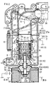
FIG.2 is a longitudinal sectional view showing an exhaust gas separator of the exhaust gas treatment device inFIG.1 . -
FIGS.3A and 3B are views showing the exhaust gas separator inFIG.2 , whereinFIG.3A is a plan view showing a central cylinder and a peripheral wall of an exhaust gas swirl chamber andFIG.3B is a sectional view taken along the line IIIB-IIIB ofFIG.2 . -
FIGS.4A to 4C are views showing the central cylinder used in the exhaust gas separator inFIG.2 , whereinFIG.4A is a cross-sectional plan view showing the central cylinder,FIG.4B is a longitudinal sectional view showing the terminal end portion of the central cylinder, andFIG.4C is a bottom view thereof. -
FIG.5 is a side view showing an exhaust manifold having the exhaust gas separator ofFIG.2 . -
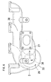
FIG.6 is a plan view showing the exhaust manifold having the exhaust gas separator ofFIG.2 . -
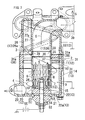
FIG.7 is a longitudinal sectional view showing an exhaust gas separator of an exhaust gas treatment device of a diesel engine according to a second embodiment of the present invention. -
FIGS.8A and 8B are views showing the exhaust gas separator inFIG.7 , whereinFIG.8A is an exploded perspective view showing the exhaust gas separator when seen slantly from the top side thereof andFIG.8B is an exploded perspective view showing the exhaust gas separator when seen slantly from the underside thereof. -
FIGS.1 to 6 show an exhaust gas treatment device of a diesel engine according to a first embodiment of the present invention, andFIGS. 7 to 8B show an exhaust gas treatment device of a diesel engine according to a second embodiment of the present invention. Hereinafter, an explanation on the exhaust gas treatment device of a diesel engine according to the preferred embodiments of the present invention will be given with reference to the attached drawings. - First, the configuration of the exhaust gas treatment device of a diesel engine according to the first embodiment of the present invention will be explained.
As shown inFIG.1 , anexhaust gas separator 2 is disposed on an exhaustgas flow passage 1 to allow PM inexhaust gas 3 to be localizedly positioned and thus to separate theexhaust gas 3 intoEGR gas 4 containing the localizedly positioned PM andemission gas 5 as the rest of theexhaust gas 3, thereby recirculating theEGR gas 4 to acombustion chamber 42 and emitting theemission gas 5 to the air.
The exhaustgas flow passage 1 is formed by sequentially connecting anexhaust port 43, anexhaust manifold 39, theexhaust gas separator 2 and anexhaust turbine 41 of asupercharger 40. TheEGR gas 4 is recirculated to an intakeair flow passage 47 via anEGR cooler 44, anEGR valve chamber 45 and acheck valve chamber 46, sequentially. The intakeair flow passage 47 is formed by sequentially connecting acompressor 48 of thesupercharger 40, a superchargingpipe 56, anintake manifold 49, and anintake port 50. AnEGR valve 45a of theEGR valve chamber 45 is opened and closed by means of avalve actuator 45b in such a manner as to be adjusted in the degree of opening in accordance with the RPM and load of the engine. - Next, the configuration of the
exhaust gas separator 2 will be explained.
As shown inFIG.2 , theexhaust gas separator 2 has acentral cylinder 7 disposed at the center thereof, and thecentral cylinder 7 has a plurality of emission gas entry holes 8 formed along the peripheral wall thereof and an exhaustgas swirl chamber 9 formed therearound. Further,electrodes exhaust gas separator 2, and the PM in theexhaust gas 3 becomes charged to a given polarity by means of corona discharge occurring between theelectrodes
Aperipheral wall 14 is formed to surround the exhaustgas swirl chamber 9 and has theelectrode 13 having the opposite polarity to the charged PM, such that the charged PM in theexhaust gas 3 swirling the exhaustgas swirl chamber 9 is localizedly positioned around theperipheral wall 14 of the exhaustgas swirl chamber 9 through a centrifugal force and an electrostatic force. Next, theexhaust gas 3 containing the localizedly positioned PM is separated as theEGR gas 4 and is sent to aterminal end portion 15 of the exhaustgas swirl chamber 9, and theexhaust gas 3 around thecentral cylinder 7 is separated as theemission gas 5 and is sent to the interior of thecentral cylinder 7 through the plurality of emission gas entry holes 8. - In the first embodiment of the present invention, the PM is charged to a negative polarity. Further, as shown in
FIG.2 , thecentral cylinder 7 has theelectrode 12 having the same negative polarity as the PM.
As shown inFIG. 2 , thecentral cylinder 7 has a tubelike shape and the emission gas entry holes 8 are spaced apart serially from each other by a given distance along the generating line of thecentral cylinder 7, such that the series of emission gas entry holes 8 are spaced apart from each other by a given distance along the outer peripheral direction of thecentral cylinder 7. As shown inFIG.4A , each of the emission gas entry holes 8 has anacute angle portion 8a formed on the opened periphery thereof. Thus, the emission gas entry holes 8 formed toward the interior of thecentral cylinder 7 from the exhaustgas swirl chamber 9 have the reverse directions to the swirl direction of theexhaust gas 3. As shown inFIG.4A , theacute angle portion 8a is a portion being at an acute angle on the section perpendicular to the central axis of thecentral cylinder 7. Since thecentral cylinder 7 has theelectrode 12 having the same polarity as the charged PM in the first embodiment of the present invention, the corona discharge occurs between thecentral cylinder 7 and theperipheral wall 14 of the exhaustgas swirl chamber 9 having theelectrode 13 having the different polarity from the charged PM, thereby effectively charging exhaust particles in the exhaustgas swirl chamber 9. - As shown in
FIGS.2 and3A , thecentral cylinder 7 has theelectrode 12 having the same polarity as the charged PM and a plurality ofdischarge protrusions 6 formed protrudedly from the outer periphery thereof toward theperipheral wall 14 of the exhaustgas swirl chamber 9.
As shown inFIG.2 , thedischarge protrusions 6 have theelectrodes 12 having the same negative polarity as the charged PM, and they are molded integrally with thecentral cylinder 7. - As shown in
FIGS.2 and3A , thedischarge protrusions 6 are formed serially along the outer periphery of thecentral cylinder 7, such that the series ofdischarge protrusions 6 are arranged in the axial length of thecentral cylinder 7.
As shown inFIG.3A , each of the series ofdischarge protrusions 6 formed along the outer periphery of thecentral cylinder 7 has a shape of a saw tooth. As shown inFIG.2 , the three series ofdischarge protrusions 6 are formed adjacent to each other along the startingend portion 10 of the exhaustgas swirl chamber 9, that is, on the upstream side of the most upstream positioned emission gas entry holes 8.
As shown inFIG.2 , in the arrangements of the emission gas entry holes 8 along the axial length of thecentral cylinder 7, thedischarge protrusions 6 are formed between the emission gas entry holes 8 adjacent to each other along the axial length of thecentral cylinder 7. Each of thedischarge protrusions 6 is formed between the emission gas entry holes 8 adjacent to each other.
As shown inFIG.2 , an exhaust gasdeflection guide wall 18 is disposed on the upstream side of thedischarge protrusions 6, and theexhaust gas 3 toward thedischarge protrusions 6 is deflected to theperipheral wall 14 of the exhaustgas swirl chamber 9 around thedischarge protrusions 6 by means of the exhaust gasdeflection guide wall 18. The outer periphery of the exhaust gasdeflection guide wall 18 is a curved shape taken by concavedly forming a peripheral surface shape of a truncated cone having a gradually large diameter as it goes toward the downstream side thereof on the inside thereof. - As shown in
FIG.2 , a central cylinderterminal end wall 20 is disposed along a central cylinderterminal end portion 19 surrounded by theterminal end portion 15 of the exhaustgas swirl chamber 9, and an EGRgas swirl chamber 21 is disposed adjacent to theterminal end portion 15 of the exhaustgas swirl chamber 9. Next, anEGR gas outlet 23 is formed on aperipheral wall 22 surrounding the EGRgas swirl chamber 21, and gas vent holes 24 are formed along the central cylinderterminal end wall 20, such thatgas components 25 of theEGR gas 4 overflowing from the center of the EGRgas swirl chamber 21 move from the gas vent holes 24 to the interior of thecentral cylinder 7, as theemission gas 5. - As shown in
FIG.2 , theperipheral wall 22 of the EGRgas swirl chamber 21 and anend wall 22a of the EGRgas swirl chamber 21 have theelectrodes 13 having the positive polarities different from the charged PM. Also, the central cylinderterminal end wall 20 has theelectrode 12 having the same negative polarity as the charged PM. The central cylinderterminal end wall 20 is molded integrally with the peripheral wall of thecentral cylinder 7. - As shown in
FIG.4B , each of the gas vent holes 24 has an acute angle portion 24a formed on the opened periphery thereof. Thus, as shown inFIGS. 4B and 4C , the gas vent holes 24 formed toward the interior of thecentral cylinder 7 from the center of the EGRgas swirl chamber 21 have the reverse directions to the swirl direction of theEGR gas 4. As shown inFIG.4B , the acute angle portion 24a is a portion being at an acute angle on the section in parallel to the central axis of thecentral cylinder 7 and containing the central axis of eachgas vent hole 24. As shown inFIG. 2 , thecentral cylinder 7 is disposed in up and down directions, and the central cylinderterminal end wall 20 is disposed along the bottom end periphery of thecentral cylinder 7. As shown inFIG.4B , the gas vent holes 24 are formed inclined downwardly toward the EGRgas swirl chamber 21 from the interior of thecentral cylinder 7, and during the stop of the engine, the PM accumulating in thecentral cylinder 7 moves from the gas vent holes 24 toward the EGRgas swirl chamber 21 by means of the self gravity thereof. - As shown in
FIG.2 , an exhaust gasswirl approach passage 26 is formed along a spirally formedapproach guide wall 26a on the upstream side of the exhaustgas swirl chamber 9.
As shown inFIG.2 , an emission gas-emittingpassage 27 is formed at the center of theexhaust gas separator 2 surrounded by the exhaust gasswirl approach passage 26, and aninlet 28 of the emission gas-emittingpassage 27 is formed to communicate with anoutlet 30 formed along a startingend portion 29 of thecentral cylinder 7.
As shown inFIG.2 , theperipheral wall 14 of the exhaustgas swirl chamber 9 and aperipheral wall 33 of the exhaust gasswirl approach passage 26 are coupled to each other by means of a mountingbolt 61.
The emission gas-emittingpassage 27 has aperipheral wall 27a divided into aperipheral wall 35 of theinlet 28 of the emission gas-emittingpassage 27 and a downstream sideperipheral wall 36 of the emission gas-emittingpassage 27 positioned downstream from theperipheral wall 35, and theperipheral wall 35 is interposed between the downstream sideperipheral wall 36 of the emission gas-emittingpassage 27 and aperipheral wall 37 of theoutlet 30 of thecentral cylinder 7. - The
peripheral wall 35 of theinlet 28 of the emission gas-emittingpassage 27 is molded of an electrical insulator so as to electrically insulate theperipheral wall 14 of the exhaustgas swirl chamber 9, theperipheral wall 33 of the exhaust gasswirl approach passage 26 and the downstream sideperipheral wall 36 of the emission gas-emittingpassage 27, which have theelectrodes 13 having different polarities from thecentral cylinder 7, from thecentral cylinder 7.
Theperipheral wall 35 of theinlet 28 of the emission gas-emittingpassage 27 is made from aluminum oxide. - As shown in
FIG.2 , aninput terminal 52 toward thedischarge protrusions 6 is connected to thedischarge protrusions 6 through thecentral cylinder 7. Theinput terminal 52 and thecentral cylinder 7 are electrically insulated from theend wall 22a of the EGRgas swirl chamber 21 by means ofspacers input terminal 52. Theinput terminal 52 toward thenegative electrode 12 provided at thecentral cylinder 7 or thedischarge protrusions 6 is connected to anegative output terminal 58a of a boostingcircuit 58 by means of aconductive plate 62. The positive output of the boostingcircuit 58 is connected to earth.
Theperipheral wall 14 of the exhaustgas swirl chamber 9, theperipheral wall 22 of the EGRgas swirl chamber 21, theend wall 22a of the EGRgas swirl chamber 21, theperipheral wall 33 of the exhaust gasswirl approach passage 26, the downstream sideperipheral wall 36 of the emission gas-emittingpassage 27 and theapproach guide wall 26a, which have thepositive electrodes 13, are connected to earth (negative pole of battery) through a body of the engine. Areference numeral 55 in the drawing denotes a battery, and 58b denotes a positive input terminal of the boostingcircuit 58.
Aninsulation tube 66 is disposed at the coupled portion between thespacers input terminal 52, thereby preventing discharge between theinput terminal 52 and theend wall 22a of the EGRgas swirl chamber 21 from occurring. - As shown in
FIGS.2 ,5 and6 , theperipheral wall 33 of the exhaust gasswirl approach passage 26, the downstream sideperipheral wall 36 of the emission gas-emittingpassage 27 and theapproach guide wall 26a are molded integrally with theexhaust manifold 39. They are an integral casting product made of cast iron. - As shown in
FIG.1 , theexhaust gas separator 2 is disposed upstream of theexhaust turbine 41 of thesupercharger 40. Also, theemission gas 5 is emitted to the air without using the DPF that regenerates by burning and removing the PM caught from theexhaust gas 3. - As shown in
FIGS.2 and3A , a circuit-accommodatingcase 57 is mounted on the end portion of theexhaust gas separator 2 so as to accommodate the boostingcircuit 58 therein, and the boosted voltage through the boostingcircuit 58 is applied to theelectrodes exhaust gas separator 2.
Aconductor 59 electrically connected to the boostingcircuit 58 is passed through anend wall 60 of theexhaust gas separator 2, and by means of theconductor 59, the boosted voltage through the boostingcircuit 58 is applied to theelectrodes exhaust gas separator 2.
Theconductor 59 becomes theinput terminal 52, and theinput terminal 52 is electrically connected to thenegative output terminal 58a of the boostingcircuit 58 through theconductive plate 62.
The circuit-accommodatingcase 57 takes a round-like shape and has theinput terminal 52 and theconductive plate 62 posited at the center thereof and the boostingcircuit 58 accommodated in a case around theinput terminal 52 and theconductive plate 62. Theconductive plate 62 is fixedly fitted between theinsulator spacer 54 fitted around theinput terminal 52 and a conductor washer 63, in such a manner as to be electrically connected to theinput terminal 52. The circuit-accommodatingcase 57 further has a heat insulatingair chamber 64 formed at the upper side of the boostingcircuit 58. - Through the following description, the differences of the second embodiment of the present invention as shown in
FIGS.7 to 8B from the first embodiment of the present invention will be given.
Exhaust gasswirl guide wings 11 are disposed along the startingend portion 10 of the exhaustgas swirl chamber 9 and have theelectrode 12 having the same polarity as the charged PM andacute angle portions edge portions
Through the rectifying action of the exhaust gasswirl guide wings 11, the swirl speed of theexhaust gas 3 in the exhaustgas swirl chamber 9 can be improved, and the centrifugal force applied to the PM in theexhaust gas 3 becomes larger, thereby increasing the concentration of PM of theEGR gas 4.
Further, the corona discharge occurs between the exhaust gasswirl guide wings 11 and theperipheral wall 14 of the exhaustgas swirl chamber 9 having theelectrode 13 having the different polarity from the charged PM, thereby effectively charging exhaust particles in the exhaustgas swirl chamber 9.
Also, the PM in theexhaust gas 3 can be effectively charged because a concentrated portion in the electric field is formed around theacute angle portions - The exhaust gas
swirl guide wings 11 are disposed along the startingend portion 10 of the exhaustgas swirl chamber 9 and have theelectrode 12 with the different polarity from that of theelectrode 13 provided on theperipheral wall 33 surrounding the exhaust gasswirl approach passage 26.
That is, the exhaust gasswirl guide wings 11 have thenegative electrode 12, and theperipheral wall 33 has thepositive electrode 13. - The starting
end portion 10 of the exhaustgas swirl chamber 9 is disposed around theperipheral wall 37 of theoutlet 30 of thecentral cylinder 7, and theperipheral wall 14 of the exhaustgas swirl chamber 9 is divided into aperipheral wall 31 surrounding the startingend portion 10 of the exhaustgas swirl chamber 9 and a downstream sideperipheral wall 32 of the exhaustgas swirl chamber 9 formed downstream from theperipheral wall 31. Theperipheral wall 31 surrounding the startingend portion 10 of the exhaustgas swirl chamber 9 is interposed between theperipheral wall 33 of the exhaust gasswirl approach passage 26 and the downstream sideperipheral wall 32.
Theperipheral wall 27a of the emission gas-emittingpassage 27 is divided into theperipheral wall 35 of theinlet 28 of the emission gas-emittingpassage 27 and the downstream sideperipheral wall 36 positioned downstream from theperipheral wall 35, and theperipheral wall 35 is interposed between the downstream sideperipheral wall 36 and theperipheral wall 37 of theoutlet 30 of thecentral cylinder 7. Theperipheral wall 31 of the startingend portion 10 of the exhaustgas swirl chamber 9, theperipheral wall 35 of theinlet 28 of the emission gas-emittingpassage 27, and crosslinkers 31a connecting them are molded integrally with one another, as an electrical insulator, which electrically insulate the downstream sideperipheral wall 32 of the exhaustgas swirl chamber 9, theperipheral wall 33 of the exhaust gasswirl approach passage 26 and the downstream sideperipheral wall 36 of the emission gas-emittingpassage 27, which have theelectrodes 13 having different polarities from the exhaust gasswirl guide wings 11, from thecentral cylinder 7 having theelectrode 12 having the same polarity as the exhaust gasswirl guide wings 11.
Moreover, the electrical insulator electrically insulates theperipheral wall 22 of the EGRgas swirl chamber 21 and theend wall 22a of the EGRgas swirl chamber 21, which have theelectrodes 13 having different polarities from thecentral cylinder 7, from thecentral cylinder 7. The electrical insulator is made from aluminum oxide.
The assembly of the insulation parts can be conducted simultaneously. - The cross-linkers 31a are formed of upstream exhaust gas
swirl guide wings 38 positioned upstream of the exhaust gasswirl guide wings 11. Through the rectifying action of the upstream exhaust gasswirl guide wings 38, therefore, the swirl speed of theexhaust gas 3 in the exhaustgas swirl chamber 9 can be improved, and the centrifugal force applied to the PM in theexhaust gas 3 becomes larger, thereby increasing the concentration of PM of theEGR gas 4.
Other configurations and functions of the second embodiment of the present invention are the same as those of the first embodiment of the present invention, and the same components inFIGS.7 to 8B as in the first embodiments of the present invention are denoted by the same reference numerals as the first embodiment. - The present invention is conducted with the above-mentioned preferred embodiments, but it is not limited thereto. That is, the PM may be charged to the positive polarity, and in this case, the
central cylinder 7 or the exhaust gasswirl guide wings 11 has the positive electrode having the same polarity as the charged PM, while the downstream sideperipheral wall 32 of the exhaustgas swirl chamber 9, theperipheral wall 22 of the EGRgas swirl chamber 21, theend wall 22a of the EGRgas swirl chamber 21, theperipheral wall 33 of the exhaust gasswirl approach passage 26, the downstream sideperipheral wall 36 of the emission gas-emittingpassage 27, and theapproach guide wall 26a have the negative electrode having the different polarity from the charged PM.
While the present invention has been described with reference to the particular illustrative embodiments, it is not to be restricted by the embodiments but only by the appended claims. It is to be appreciated that those skilled in the art can change or modify the embodiments without departing from the scope and spirit of the present invention. -
- 1:
- exhaust gas flow passage
- 2:
- exhaust gas separator
- 3:
- exhaust gas
- 4:
- EGR gas
- 5:
- emission gas
- 6:
- discharge protrusions
- 7:
- central cylinder
- 8:
- emission gas entry hole
- 8a:
- acute angle portion
- 9:
- exhaust gas swirl chamber
- 12:
- electrode
- 13:
- electrode
- 14:
- peripheral wall of exhaust gas swirl chamber
- 15:
- terminal end portion of exhaust gas swirl chamber
- 18:
- exhaust gas deflection guide wall
- 19:
- central cylinder terminal end portion
- 20:
- terminal end wall of central cylinder
- 21:
- EGR gas swirl chamber
- 22:
- peripheral wall of EGR gas swirl chamber
- 23:
- EGR gas outlet
- 24:
- gas vent holes
- 24a:
- acute angle portion
- 25:
- gas components
- 26:
- exhaust gas swirl approach passage
- 26a:
- approach guide wall
- 27:
- emission gas-emitting passage
- 27a:
- peripheral wall of emission gas-emitting passage
- 28:
- inlet of emission gas-emitting passage
- 29:
- starting end portion of central cylinder
- 30:
- outlet of central cylinder
- 33:
- peripheral wall of exhaust gas swirl approach passage
- 35:
- peripheral wall of inlet of emission gas-emitting passage
- 36:
- downstream side peripheral wall of emission gas-emitting passage
- 37:
- peripheral wall of outlet of central cylinder
- 39:
- exhaust manifold
- 40:
- supercharger
- 41:
- exhaust turbine
- 57:
- circuit-accommodating case
- 58:
- boosting circuit
- 59:
- conductor
- 60:
- end wall
Claims (22)
- An exhaust gas treatment device of a diesel engine having an exhaust gas separator 2 disposed on an exhaust gas flow passage 1 to allow PM in exhaust gas 3 to be localizedly positioned and thus to separate the exhaust gas 3 into EGR gas 4 containing the localizedly positioned PM and emission gas 5 as the rest of the exhaust gas 3, thereby recirculating the EGR gas 4 to a combustion chamber 42 and emitting the emission gas 5 to the air, the exhaust gas treatment device comprising:a central cylinder 7 disposed at the center of the exhaust gas separator 2 and having a plurality of emission gas entry holes 8 formed along the periphery wall thereof; andan exhaust gas swirl chamber 9 formed around the central cylinder 7,wherein the exhaust gas separator 2 has electrodes 12 and 13 having different polarities from each other to allow the PM in the exhaust gas 3 to be charged to a given polarity by means of corona discharge between the electrodes 12 and 13 and thus to permit a peripheral wall 14 surrounding the exhaust gas swirl chamber 9 to have the electrode 13 having the opposite polarity to the charged PM, and the charged PM in the exhaust gas 3 swirling the exhaust gas swirl chamber 9 is localizedly positioned around the peripheral wall 14 of the exhaust gas swirl chamber 9 through a centrifugal force and an electrostatic force to allow the exhaust gas 3 containing the localizedly positioned PM to be separated as the EGR gas 4 and sent to a terminal end portion 15 of the exhaust gas swirl chamber 9, while the exhaust gas 3 around the central cylinder 7 is being separated as the emission gas 5 and sent to the interior of the central cylinder 7 through the plurality of emission gas entry holes 8.
- The exhaust gas treatment device of a diesel engine according to claim 1, wherein the central cylinder 7 has the electrode 12 having the same polarity as the charged PM.
- The exhaust gas treatment device of a diesel engine according to claim 2, wherein each of the emission gas entry holes 8 has an acute angle portion 8a formed on the opened periphery thereof.
- The exhaust gas treatment device of a diesel engine according to any one of claims 1 to 3, wherein the emission gas entry holes 8 formed toward the interior of the central cylinder 7 from the exhaust gas swirl chamber 9 have the reverse direction to the swirl direction of the exhaust gas 3.
- The exhaust gas treatment device of a diesel engine according to any one of claims 1 to 4, wherein the central cylinder 7 has the electrode 12 having the same polarity as the charged PM and a plurality of discharge protrusions 6 formed protrudedly from the outer periphery thereof toward the peripheral wall 14 of the exhaust gas swirl chamber 9.
- The exhaust gas treatment device of a diesel engine according to claim 5, wherein when the plurality of emission gas entry holes 8 are formed in the axial direction of the central cylinder 7, the plurality of discharge protrusions 6 are formed between the emission gas entry holes 8 formed serially in the axial direction of the central cylinder 7.
- The exhaust gas treatment device of a diesel engine according to claim 5 or 6, wherein the discharge protrusions 6 have an exhaust gas deflection guide wall 18 disposed on the upstream side thereof, such that the exhaust gas 3 moving toward the discharge protrusions 6 is deflected to the peripheral wall 14 of the exhaust gas swirl chamber 9 around the discharge protrusions 6 by means of the exhaust gas deflection guide wall 18.
- The exhaust gas treatment device of a diesel engine according to any one of claims 1 to 7, wherein a terminal end wall 20 is disposed along a terminal end portion 19 of the central cylinder 7 surrounded by the terminal end portion 15 of the exhaust gas swirl chamber 9, an EGR gas swirl chamber 21 is disposed adjacent to the terminal end portion 15 of the exhaust gas swirl chamber 9, an EGR gas outlet 23 is formed on a peripheral wall 22 surrounding the EGR gas swirl chamber 21, and gas vent holes 24 are formed along the terminal end wall 20 of the central cylinder 7, such that gas components 25 of the EGR gas 4 overflowing from the center of the EGR gas swirl chamber 21 move from the gas vent holes 24 to the interior of the central cylinder 7, as the emission gas 5.
- The exhaust gas treatment device of a diesel engine according to claim 8, wherein the peripheral wall 22 of the EGR gas swirl chamber 21 has the electrode 13 having the different polarity from the charged PM.
- The exhaust gas treatment device of a diesel engine according to claim 9, wherein the terminal end wall 20 of the central cylinder 7 has the electrode 12 having the same polarity as the charged PM.
- The exhaust gas treatment device of a diesel engine according to claim 10, wherein each of the gas vent holes 24 has the acute angle portion 24a formed on the opened periphery thereof.
- The exhaust gas treatment device of a diesel engine according to any one of claims 8 to 11, wherein the gas vent holes 24 formed toward the interior of the central cylinder 7 from the center of the EGR gas swirl chamber 21 have the reverse direction to the swirl direction of the EGR gas 4.
- The exhaust gas treatment device of a diesel engine according to any one of claims 1 to 12, wherein the exhaust gas swirl chamber 9 has an exhaust gas swirl approach passage 26 formed along a spirally formed approach guide wall 26a on the upstream side thereof.
- The exhaust gas treatment device of a diesel engine according to claim 13, wherein the exhaust gas separator 2 surrounded by the exhaust gas swirl approach passage 26 has an emission gas-emitting passage 27 formed at the center thereof, and the emission gas-emitting passage 27 has an inlet 28 formed to communicate with an outlet 30 formed along a starting end portion 29 of the central cylinder 7.
- The exhaust gas treatment device of a diesel engine according to claim 13 or 14, wherein the central cylinder 7 and the peripheral wall 33 surrounding the exhaust gas swirl approach passage 26 have the electrodes 12 and 13 having different polarities from each other.
- The exhaust gas treatment device of a diesel engine according to claim 15, wherein the emission gas-emitting passage 27 has a peripheral wall 27a divided into a peripheral wall 35 of the inlet 28 thereof and a downstream side peripheral wall 36 positioned downstream from the peripheral wall 35, and the peripheral wall 35 is interposed between the downstream side peripheral wall 36 of the emission gas-emitting passage 27 and a peripheral wall 37 of the outlet 30 of the central cylinder 7 and being molded of an electrical insulator so as to electrically insulate the peripheral wall 14 of the exhaust gas swirl chamber 9, the peripheral wall 33 of the exhaust gas swirl approach passage 26 and the downstream side peripheral wall 36 of the emission gas-emitting passage 27, which have the electrodes 13 having different polarities from the central cylinder 7, from the central cylinder 7.
- The exhaust gas treatment device of a diesel engine according to claim 16, wherein the central cylinder 7 has the electrode 12 having the same polarity as the charged PM and the plurality of discharge protrusions 6 formed protrudedly from the outer periphery thereof toward the peripheral wall 14 of the exhaust gas swirl chamber 9, and the peripheral wall 35 of the inlet 28 of the emission gas-emitting passage 27 is formed of the exhaust gas deflection guide wall 18, such that the exhaust gas 3 moving toward the discharge protrusions 6 is deflected to the peripheral wall 14 of the exhaust gas swirl chamber 9 around the discharge protrusions 6 by means of the exhaust gas deflection guide wall 18.
- The exhaust gas treatment device of a diesel engine according to claim 16 or 17, wherein the peripheral wall 33 of the exhaust gas swirl approach passage 26 and the downstream side peripheral wall 36 of the emission gas-emitting passage 27 are molded integrally with the exhaust manifold 39.
- The exhaust gas treatment device of a diesel engine according to any one of claims 1 to 18, wherein the exhaust gas separator 2 is disposed upstream of an exhaust turbine 41 of a supercharger 40.
- The exhaust gas treatment device of a diesel engine according to any one of claims 1 to 19, wherein the emission gas 5 is emitted to the air without using the DPF that regenerates by burning and removing the PM caught from the exhaust gas 3.
- The exhaust gas treatment device of a diesel engine according to any one of claims 1 to 20, wherein the exhaust gas separator 2 has a circuit-accommodating case 57 mounted on the end portion thereof so as to accommodate a boosting circuit 58 therein, and the boosted voltage through the boosting circuit 58 is applied to the electrodes 12 and 13 of the exhaust gas separator 2.
- The exhaust gas treatment device of a diesel engine according to claim 21, wherein the boosting circuit 58 has a conductor 59 electrically connected thereto, the conductor 59 being passed through an end wall 60 of the exhaust gas separator 2, such that by means of the conductor 59, the boosted voltage through the boosting circuit 58 is applied to the electrodes 12 and 13 of the exhaust gas separator 2.
Applications Claiming Priority (3)
| Application Number | Priority Date | Filing Date | Title |
|---|---|---|---|
| JP2009110495 | 2009-04-30 | ||
| JP2010019932A JP5351791B2 (en) | 2009-04-30 | 2010-02-01 | Diesel engine exhaust treatment equipment |
| PCT/JP2010/054216 WO2010125865A1 (en) | 2009-04-30 | 2010-03-12 | Multi-cylinder engine |
Publications (3)
| Publication Number | Publication Date |
|---|---|
| EP2426325A1 true EP2426325A1 (en) | 2012-03-07 |
| EP2426325A4 EP2426325A4 (en) | 2014-10-15 |
| EP2426325B1 EP2426325B1 (en) | 2017-08-02 |
Family
ID=43032018
Family Applications (1)
| Application Number | Title | Priority Date | Filing Date |
|---|---|---|---|
| EP10769565.2A Not-in-force EP2426325B1 (en) | 2009-04-30 | 2010-03-12 | Exhaust gas treatment device of a diesel engine |
Country Status (6)
| Country | Link |
|---|---|
| US (1) | US8793974B2 (en) |
| EP (1) | EP2426325B1 (en) |
| JP (1) | JP5351791B2 (en) |
| KR (1) | KR101672566B1 (en) |
| CN (1) | CN102362049B (en) |
| WO (1) | WO2010125865A1 (en) |
Families Citing this family (10)
| Publication number | Priority date | Publication date | Assignee | Title |
|---|---|---|---|---|
| US8627805B2 (en) * | 2010-03-27 | 2014-01-14 | Cummins Inc. | System and apparatus for controlling reverse flow in a fluid conduit |
| JP5427739B2 (en) * | 2010-09-17 | 2014-02-26 | 株式会社クボタ | Diesel engine exhaust treatment equipment |
| JP5806967B2 (en) | 2012-03-30 | 2015-11-10 | 株式会社クボタ | Diesel engine exhaust treatment equipment |
| EP3168450A1 (en) * | 2015-11-12 | 2017-05-17 | Winterthur Gas & Diesel Ltd. | Internal combustion engine, method for cleaning exhaust from an internal combustion engine and method for refitting an internal combustion engine |
| CN106499551B (en) * | 2016-10-12 | 2017-07-28 | 同济大学 | A Clean EGR Loop System |
| CN106988935B (en) * | 2016-12-13 | 2019-08-20 | 中国第一汽车股份有限公司 | An integrated device for purifying, cooling and pressurizing EGR exhaust gas |
| CN107486335A (en) * | 2017-02-07 | 2017-12-19 | 安徽鹰龙工业设计有限公司 | A kind of electrostatic precipitator of pressurization cycle absorption |
| WO2018226382A1 (en) * | 2017-06-09 | 2018-12-13 | Achates Power, Inc. | Supercharger protection in an opposed-piston engine with egr |
| CN113117906B (en) * | 2021-04-21 | 2022-01-04 | 西南石油大学 | An electrostatic cyclone composite separation device for shale hammer grinding drill cuttings dust |
| CN116273513B (en) * | 2023-02-28 | 2025-11-18 | 中国石油化工股份有限公司 | A cyclone separator, a separator device, a separator system and a method of use. |
Family Cites Families (16)
| Publication number | Priority date | Publication date | Assignee | Title |
|---|---|---|---|---|
| CA714367A (en) | 1965-07-27 | Mitsubishi Denki Kabushiki Kaisha | Electrostatic dust collector | |
| SE389461B (en) * | 1974-12-11 | 1976-11-08 | Fi Wes Maskinservice Ab | Muffler FOR COMPRESSED AIR TOOL FOR SAME SEPARATION OF LUBRICANT OIL FROM THE COMPRESSED AIR |
| DE3141156A1 (en) * | 1981-10-16 | 1983-04-28 | Robert Bosch Gmbh, 7000 Stuttgart | METHOD AND DEVICE FOR REMOVING SOLID COMPONENTS AND AEROSOLS, ESPECIALLY SOOT COMPONENTS FROM THE EXHAUST GAS FROM COMBUSTION ENGINES |
| DE3424196A1 (en) * | 1984-02-11 | 1985-08-22 | Robert Bosch Gmbh, 7000 Stuttgart | DEVICE FOR THE REMOVAL OF SOLID PARTICULAR PARTS FROM EXHAUST GASES FROM COMBUSTION ENGINES |
| DE3500375A1 (en) * | 1985-01-08 | 1986-07-10 | Robert Bosch Gmbh, 7000 Stuttgart | DEVICE FOR REMOVING SOLID PARTICLES, ESPECIALLY CARBON PARTICLES, FROM THE EXHAUST GAS FROM COMBUSTION ENGINES |
| JPH0611374B2 (en) * | 1988-09-05 | 1994-02-16 | 帝国ピストンリング株式会社 | Particle separator |
| DE3841182A1 (en) * | 1988-12-07 | 1990-06-13 | Bosch Gmbh Robert | DEVICE FOR REMOVING SOLID PARTICLES, ESPECIALLY CARBON PARTICLES, FROM THE EXHAUST WASTE FROM COMBUSTION ENGINES |
| JPH03207463A (en) * | 1990-01-11 | 1991-09-10 | Mitsubishi Heavy Ind Ltd | Dust separator |
| JP3207463B2 (en) * | 1991-09-25 | 2001-09-10 | マツダ株式会社 | Anti-skid brake system for vehicles |
| JPH05222915A (en) * | 1992-02-10 | 1993-08-31 | Nippon Soken Inc | Exhaust emission control device for internal combustion engine |
| JPH05277313A (en) * | 1992-03-31 | 1993-10-26 | Teikoku Piston Ring Co Ltd | Fine particle separating device |
| JPH06141552A (en) * | 1992-10-26 | 1994-05-20 | Kasuga Denki Kk | Power controller for high frequency high voltage power supply |
| KR20010014570A (en) * | 1999-04-23 | 2001-02-26 | 구자홍 | reduction device for the pressure of loss in cyclone dust collector |
| JP2003106137A (en) * | 2001-09-27 | 2003-04-09 | Komatsu Ltd | Exhaust gas purification device for internal combustion engine |
| JP2006346538A (en) * | 2005-06-14 | 2006-12-28 | Pauretsuku:Kk | Cyclone solid-gas separator |
| JP2007278194A (en) * | 2006-04-07 | 2007-10-25 | Hino Motors Ltd | Exhaust treatment device |
-
2010
- 2010-02-01 JP JP2010019932A patent/JP5351791B2/en not_active Expired - Fee Related
- 2010-03-12 WO PCT/JP2010/054216 patent/WO2010125865A1/en not_active Ceased
- 2010-03-12 CN CN201080012932.8A patent/CN102362049B/en not_active Expired - Fee Related
- 2010-03-12 US US13/255,951 patent/US8793974B2/en not_active Expired - Fee Related
- 2010-03-12 EP EP10769565.2A patent/EP2426325B1/en not_active Not-in-force
- 2010-03-12 KR KR1020117018464A patent/KR101672566B1/en not_active Expired - Fee Related
Also Published As
| Publication number | Publication date |
|---|---|
| EP2426325B1 (en) | 2017-08-02 |
| US20120000186A1 (en) | 2012-01-05 |
| EP2426325A4 (en) | 2014-10-15 |
| WO2010125865A1 (en) | 2010-11-04 |
| CN102362049B (en) | 2014-06-04 |
| CN102362049A (en) | 2012-02-22 |
| US8793974B2 (en) | 2014-08-05 |
| KR20120003431A (en) | 2012-01-10 |
| JP2010276012A (en) | 2010-12-09 |
| JP5351791B2 (en) | 2013-11-27 |
| KR101672566B1 (en) | 2016-11-03 |
Similar Documents
| Publication | Publication Date | Title |
|---|---|---|
| US8793974B2 (en) | Exhaust gas treatment device of diesel engine | |
| CN104302880B (en) | Use the big capacity marine diesel engine emission-control equipment of the fuel than heavy oil low-quality | |
| KR101423016B1 (en) | Exhaust gas treatment equipment for diesel engine | |
| JP2010276012A5 (en) | ||
| US4478613A (en) | Apparatus to remove solid particles and aerosols from a gas, especially from the exhaust gas of an internal combustion engine | |
| JP2016151196A (en) | Exhaust gas recirculation system and marine engine mounted with the same | |
| CN105229269A (en) | Use the discharged-gas processing device of the marine diesel engine of heavy oil | |
| JP2005256679A (en) | Intake passage of engine with EGR device | |
| CN103119257B (en) | Device for treating soot particle-containing exhaust gases | |
| CN106955786B (en) | Electrode plates, electrostatic ionization modules and hoods | |
| EP2832961B1 (en) | Exhaust treatment device for diesel engine | |
| ATE188015T1 (en) | DEVICE FOR CLEANING EXHAUST GASES FROM COMBUSTION ENGINE | |
| JP2009114872A (en) | Exhaust emission control device | |
| US20030121251A1 (en) | System for agglomerating exhausted particulate matter | |
| JP5427739B2 (en) | Diesel engine exhaust treatment equipment | |
| RU2714985C1 (en) | Device for cleaning and recycling exhaust gases | |
| US20080118410A1 (en) | Exhaust Gas Cleaner | |
| CN212744120U (en) | Electrostatic adsorption particle catcher | |
| KR101339085B1 (en) | Purifying exhaust gas | |
| US7936117B2 (en) | Structure of spark plug | |
| KR830000822Y1 (en) | Car fume dust collector | |
| RU2555711C2 (en) | Electric field inducing device in exhaust gas system | |
| CN206158822U (en) | Processing apparatus , diesel engine and car behind low temperature plasma | |
| Irzycki et al. | Impact of low-temperature corona discharges on gaseous pollutants level in diesel engine's exhaust gas | |
| Prasad et al. | Rejection Diesel Engine with Cyclonic Separator |
Legal Events
| Date | Code | Title | Description |
|---|---|---|---|
| PUAI | Public reference made under article 153(3) epc to a published international application that has entered the european phase |
Free format text: ORIGINAL CODE: 0009012 |
|
| 17P | Request for examination filed |
Effective date: 20111123 |
|
| AK | Designated contracting states |
Kind code of ref document: A1 Designated state(s): AT BE BG CH CY CZ DE DK EE ES FI FR GB GR HR HU IE IS IT LI LT LU LV MC MK MT NL NO PL PT RO SE SI SK SM TR |
|
| DAX | Request for extension of the european patent (deleted) | ||
| A4 | Supplementary search report drawn up and despatched |
Effective date: 20140911 |
|
| RIC1 | Information provided on ipc code assigned before grant |
Ipc: F01N 3/20 20060101ALN20140905BHEP Ipc: B03C 3/49 20060101ALN20140905BHEP Ipc: B04C 9/00 20060101ALN20140905BHEP Ipc: B03C 3/36 20060101ALN20140905BHEP Ipc: B03C 3/41 20060101ALN20140905BHEP Ipc: B04C 5/103 20060101ALN20140905BHEP Ipc: B03C 3/02 20060101ALN20140905BHEP Ipc: F02M 25/07 20060101ALI20140905BHEP Ipc: B03C 3/09 20060101ALN20140905BHEP Ipc: F01N 3/28 20060101ALN20140905BHEP Ipc: B03C 3/06 20060101ALN20140905BHEP Ipc: F01N 3/01 20060101ALI20140905BHEP Ipc: B03C 3/15 20060101AFI20140905BHEP Ipc: F01N 3/02 20060101ALN20140905BHEP Ipc: F01N 3/08 20060101ALI20140905BHEP Ipc: B03C 3/40 20060101ALN20140905BHEP Ipc: B04C 5/13 20060101ALN20140905BHEP |
|
| GRAP | Despatch of communication of intention to grant a patent |
Free format text: ORIGINAL CODE: EPIDOSNIGR1 |
|
| RIC1 | Information provided on ipc code assigned before grant |
Ipc: F01N 3/28 20060101ALN20161222BHEP Ipc: B04C 9/00 20060101ALN20161222BHEP Ipc: B03C 3/09 20060101ALN20161222BHEP Ipc: B04C 5/103 20060101ALN20161222BHEP Ipc: B03C 3/06 20060101ALN20161222BHEP Ipc: F01N 3/08 20060101ALI20161222BHEP Ipc: F01N 3/20 20060101ALN20161222BHEP Ipc: B03C 3/41 20060101ALN20161222BHEP Ipc: F01N 3/02 20060101ALN20161222BHEP Ipc: B03C 3/49 20060101ALN20161222BHEP Ipc: B03C 3/40 20060101ALN20161222BHEP Ipc: F02M 26/35 20160101ALI20161222BHEP Ipc: B03C 3/02 20060101ALN20161222BHEP Ipc: B03C 3/36 20060101ALN20161222BHEP Ipc: B04C 5/13 20060101ALN20161222BHEP Ipc: B03C 3/15 20060101AFI20161222BHEP Ipc: F01N 3/01 20060101ALI20161222BHEP |
|
| INTG | Intention to grant announced |
Effective date: 20170125 |
|
| GRAS | Grant fee paid |
Free format text: ORIGINAL CODE: EPIDOSNIGR3 |
|
| GRAJ | Information related to disapproval of communication of intention to grant by the applicant or resumption of examination proceedings by the epo deleted |
Free format text: ORIGINAL CODE: EPIDOSDIGR1 |
|
| GRAL | Information related to payment of fee for publishing/printing deleted |
Free format text: ORIGINAL CODE: EPIDOSDIGR3 |
|
| REG | Reference to a national code |
Ref country code: DE Ref legal event code: R079 Ref document number: 602010044091 Country of ref document: DE Free format text: PREVIOUS MAIN CLASS: F01N0003020000 Ipc: B03C0003150000 |
|
| INTC | Intention to grant announced (deleted) | ||
| GRAR | Information related to intention to grant a patent recorded |
Free format text: ORIGINAL CODE: EPIDOSNIGR71 |
|
| GRAA | (expected) grant |
Free format text: ORIGINAL CODE: 0009210 |
|
| RIC1 | Information provided on ipc code assigned before grant |
Ipc: B03C 3/49 20060101ALN20170607BHEP Ipc: B03C 3/41 20060101ALN20170607BHEP Ipc: F02M 26/35 20160101ALI20170607BHEP Ipc: B04C 9/00 20060101ALN20170607BHEP Ipc: F01N 3/08 20060101ALI20170607BHEP Ipc: B04C 5/13 20060101ALN20170607BHEP Ipc: B03C 3/36 20060101ALN20170607BHEP Ipc: B03C 3/15 20060101AFI20170607BHEP Ipc: B04C 5/103 20060101ALN20170607BHEP Ipc: F01N 3/01 20060101ALI20170607BHEP Ipc: F01N 3/02 20060101ALN20170607BHEP Ipc: B03C 3/06 20060101ALN20170607BHEP Ipc: B03C 3/02 20060101ALN20170607BHEP Ipc: F01N 3/20 20060101ALN20170607BHEP Ipc: B03C 3/40 20060101ALN20170607BHEP Ipc: F01N 3/28 20060101ALN20170607BHEP Ipc: B03C 3/09 20060101ALN20170607BHEP |
|
| AK | Designated contracting states |
Kind code of ref document: B1 Designated state(s): AT BE BG CH CY CZ DE DK EE ES FI FR GB GR HR HU IE IS IT LI LT LU LV MC MK MT NL NO PL PT RO SE SI SK SM TR |
|
| INTG | Intention to grant announced |
Effective date: 20170627 |
|
| REG | Reference to a national code |
Ref country code: GB Ref legal event code: FG4D |
|
| REG | Reference to a national code |
Ref country code: CH Ref legal event code: EP Ref country code: AT Ref legal event code: REF Ref document number: 913868 Country of ref document: AT Kind code of ref document: T Effective date: 20170815 |
|
| REG | Reference to a national code |
Ref country code: IE Ref legal event code: FG4D |
|
| REG | Reference to a national code |
Ref country code: DE Ref legal event code: R096 Ref document number: 602010044091 Country of ref document: DE |
|
| REG | Reference to a national code |
Ref country code: NL Ref legal event code: MP Effective date: 20170802 |
|
| REG | Reference to a national code |
Ref country code: AT Ref legal event code: MK05 Ref document number: 913868 Country of ref document: AT Kind code of ref document: T Effective date: 20170802 |
|
| REG | Reference to a national code |
Ref country code: LT Ref legal event code: MG4D |
|
| PG25 | Lapsed in a contracting state [announced via postgrant information from national office to epo] |
Ref country code: SE Free format text: LAPSE BECAUSE OF FAILURE TO SUBMIT A TRANSLATION OF THE DESCRIPTION OR TO PAY THE FEE WITHIN THE PRESCRIBED TIME-LIMIT Effective date: 20170802 Ref country code: FI Free format text: LAPSE BECAUSE OF FAILURE TO SUBMIT A TRANSLATION OF THE DESCRIPTION OR TO PAY THE FEE WITHIN THE PRESCRIBED TIME-LIMIT Effective date: 20170802 Ref country code: AT Free format text: LAPSE BECAUSE OF FAILURE TO SUBMIT A TRANSLATION OF THE DESCRIPTION OR TO PAY THE FEE WITHIN THE PRESCRIBED TIME-LIMIT Effective date: 20170802 Ref country code: NL Free format text: LAPSE BECAUSE OF FAILURE TO SUBMIT A TRANSLATION OF THE DESCRIPTION OR TO PAY THE FEE WITHIN THE PRESCRIBED TIME-LIMIT Effective date: 20170802 Ref country code: HR Free format text: LAPSE BECAUSE OF FAILURE TO SUBMIT A TRANSLATION OF THE DESCRIPTION OR TO PAY THE FEE WITHIN THE PRESCRIBED TIME-LIMIT Effective date: 20170802 Ref country code: LT Free format text: LAPSE BECAUSE OF FAILURE TO SUBMIT A TRANSLATION OF THE DESCRIPTION OR TO PAY THE FEE WITHIN THE PRESCRIBED TIME-LIMIT Effective date: 20170802 Ref country code: NO Free format text: LAPSE BECAUSE OF FAILURE TO SUBMIT A TRANSLATION OF THE DESCRIPTION OR TO PAY THE FEE WITHIN THE PRESCRIBED TIME-LIMIT Effective date: 20171102 |
|
| REG | Reference to a national code |
Ref country code: FR Ref legal event code: PLFP Year of fee payment: 9 |
|
| PG25 | Lapsed in a contracting state [announced via postgrant information from national office to epo] |
Ref country code: ES Free format text: LAPSE BECAUSE OF FAILURE TO SUBMIT A TRANSLATION OF THE DESCRIPTION OR TO PAY THE FEE WITHIN THE PRESCRIBED TIME-LIMIT Effective date: 20170802 Ref country code: IS Free format text: LAPSE BECAUSE OF FAILURE TO SUBMIT A TRANSLATION OF THE DESCRIPTION OR TO PAY THE FEE WITHIN THE PRESCRIBED TIME-LIMIT Effective date: 20171202 Ref country code: BG Free format text: LAPSE BECAUSE OF FAILURE TO SUBMIT A TRANSLATION OF THE DESCRIPTION OR TO PAY THE FEE WITHIN THE PRESCRIBED TIME-LIMIT Effective date: 20171102 Ref country code: PL Free format text: LAPSE BECAUSE OF FAILURE TO SUBMIT A TRANSLATION OF THE DESCRIPTION OR TO PAY THE FEE WITHIN THE PRESCRIBED TIME-LIMIT Effective date: 20170802 Ref country code: GR Free format text: LAPSE BECAUSE OF FAILURE TO SUBMIT A TRANSLATION OF THE DESCRIPTION OR TO PAY THE FEE WITHIN THE PRESCRIBED TIME-LIMIT Effective date: 20171103 Ref country code: LV Free format text: LAPSE BECAUSE OF FAILURE TO SUBMIT A TRANSLATION OF THE DESCRIPTION OR TO PAY THE FEE WITHIN THE PRESCRIBED TIME-LIMIT Effective date: 20170802 |
|
| PG25 | Lapsed in a contracting state [announced via postgrant information from national office to epo] |
Ref country code: DK Free format text: LAPSE BECAUSE OF FAILURE TO SUBMIT A TRANSLATION OF THE DESCRIPTION OR TO PAY THE FEE WITHIN THE PRESCRIBED TIME-LIMIT Effective date: 20170802 Ref country code: RO Free format text: LAPSE BECAUSE OF FAILURE TO SUBMIT A TRANSLATION OF THE DESCRIPTION OR TO PAY THE FEE WITHIN THE PRESCRIBED TIME-LIMIT Effective date: 20170802 Ref country code: CZ Free format text: LAPSE BECAUSE OF FAILURE TO SUBMIT A TRANSLATION OF THE DESCRIPTION OR TO PAY THE FEE WITHIN THE PRESCRIBED TIME-LIMIT Effective date: 20170802 |
|
| REG | Reference to a national code |
Ref country code: DE Ref legal event code: R097 Ref document number: 602010044091 Country of ref document: DE |
|
| PG25 | Lapsed in a contracting state [announced via postgrant information from national office to epo] |
Ref country code: EE Free format text: LAPSE BECAUSE OF FAILURE TO SUBMIT A TRANSLATION OF THE DESCRIPTION OR TO PAY THE FEE WITHIN THE PRESCRIBED TIME-LIMIT Effective date: 20170802 Ref country code: SK Free format text: LAPSE BECAUSE OF FAILURE TO SUBMIT A TRANSLATION OF THE DESCRIPTION OR TO PAY THE FEE WITHIN THE PRESCRIBED TIME-LIMIT Effective date: 20170802 Ref country code: SM Free format text: LAPSE BECAUSE OF FAILURE TO SUBMIT A TRANSLATION OF THE DESCRIPTION OR TO PAY THE FEE WITHIN THE PRESCRIBED TIME-LIMIT Effective date: 20170802 |
|
| PLBE | No opposition filed within time limit |
Free format text: ORIGINAL CODE: 0009261 |
|
| STAA | Information on the status of an ep patent application or granted ep patent |
Free format text: STATUS: NO OPPOSITION FILED WITHIN TIME LIMIT |
|
| 26N | No opposition filed |
Effective date: 20180503 |
|
| PG25 | Lapsed in a contracting state [announced via postgrant information from national office to epo] |
Ref country code: SI Free format text: LAPSE BECAUSE OF FAILURE TO SUBMIT A TRANSLATION OF THE DESCRIPTION OR TO PAY THE FEE WITHIN THE PRESCRIBED TIME-LIMIT Effective date: 20170802 |
|
| REG | Reference to a national code |
Ref country code: CH Ref legal event code: PL |
|
| PG25 | Lapsed in a contracting state [announced via postgrant information from national office to epo] |
Ref country code: MC Free format text: LAPSE BECAUSE OF FAILURE TO SUBMIT A TRANSLATION OF THE DESCRIPTION OR TO PAY THE FEE WITHIN THE PRESCRIBED TIME-LIMIT Effective date: 20170802 |
|
| REG | Reference to a national code |
Ref country code: BE Ref legal event code: MM Effective date: 20180331 |
|
| REG | Reference to a national code |
Ref country code: IE Ref legal event code: MM4A |
|
| PG25 | Lapsed in a contracting state [announced via postgrant information from national office to epo] |
Ref country code: LU Free format text: LAPSE BECAUSE OF NON-PAYMENT OF DUE FEES Effective date: 20180312 |
|
| PG25 | Lapsed in a contracting state [announced via postgrant information from national office to epo] |
Ref country code: IE Free format text: LAPSE BECAUSE OF NON-PAYMENT OF DUE FEES Effective date: 20180312 |
|
| PG25 | Lapsed in a contracting state [announced via postgrant information from national office to epo] |
Ref country code: LI Free format text: LAPSE BECAUSE OF NON-PAYMENT OF DUE FEES Effective date: 20180331 Ref country code: CH Free format text: LAPSE BECAUSE OF NON-PAYMENT OF DUE FEES Effective date: 20180331 Ref country code: BE Free format text: LAPSE BECAUSE OF NON-PAYMENT OF DUE FEES Effective date: 20180331 |
|
| PGFP | Annual fee paid to national office [announced via postgrant information from national office to epo] |
Ref country code: GB Payment date: 20190306 Year of fee payment: 10 Ref country code: IT Payment date: 20190326 Year of fee payment: 10 Ref country code: DE Payment date: 20190226 Year of fee payment: 10 |
|
| PGFP | Annual fee paid to national office [announced via postgrant information from national office to epo] |
Ref country code: FR Payment date: 20190213 Year of fee payment: 10 |
|
| PG25 | Lapsed in a contracting state [announced via postgrant information from national office to epo] |
Ref country code: MT Free format text: LAPSE BECAUSE OF NON-PAYMENT OF DUE FEES Effective date: 20180312 |
|
| PG25 | Lapsed in a contracting state [announced via postgrant information from national office to epo] |
Ref country code: TR Free format text: LAPSE BECAUSE OF FAILURE TO SUBMIT A TRANSLATION OF THE DESCRIPTION OR TO PAY THE FEE WITHIN THE PRESCRIBED TIME-LIMIT Effective date: 20170802 |
|
| PG25 | Lapsed in a contracting state [announced via postgrant information from national office to epo] |
Ref country code: HU Free format text: LAPSE BECAUSE OF FAILURE TO SUBMIT A TRANSLATION OF THE DESCRIPTION OR TO PAY THE FEE WITHIN THE PRESCRIBED TIME-LIMIT; INVALID AB INITIO Effective date: 20100312 Ref country code: PT Free format text: LAPSE BECAUSE OF FAILURE TO SUBMIT A TRANSLATION OF THE DESCRIPTION OR TO PAY THE FEE WITHIN THE PRESCRIBED TIME-LIMIT Effective date: 20170802 |
|
| PG25 | Lapsed in a contracting state [announced via postgrant information from national office to epo] |
Ref country code: CY Free format text: LAPSE BECAUSE OF FAILURE TO SUBMIT A TRANSLATION OF THE DESCRIPTION OR TO PAY THE FEE WITHIN THE PRESCRIBED TIME-LIMIT Effective date: 20170802 Ref country code: MK Free format text: LAPSE BECAUSE OF NON-PAYMENT OF DUE FEES Effective date: 20170802 |
|
| REG | Reference to a national code |
Ref country code: DE Ref legal event code: R119 Ref document number: 602010044091 Country of ref document: DE |
|
| PG25 | Lapsed in a contracting state [announced via postgrant information from national office to epo] |
Ref country code: FR Free format text: LAPSE BECAUSE OF NON-PAYMENT OF DUE FEES Effective date: 20200331 Ref country code: DE Free format text: LAPSE BECAUSE OF NON-PAYMENT OF DUE FEES Effective date: 20201001 |
|
| GBPC | Gb: european patent ceased through non-payment of renewal fee |
Effective date: 20200312 |
|
| PG25 | Lapsed in a contracting state [announced via postgrant information from national office to epo] |
Ref country code: GB Free format text: LAPSE BECAUSE OF NON-PAYMENT OF DUE FEES Effective date: 20200312 |
|
| PG25 | Lapsed in a contracting state [announced via postgrant information from national office to epo] |
Ref country code: IT Free format text: LAPSE BECAUSE OF NON-PAYMENT OF DUE FEES Effective date: 20200312 |