EP2426320A1 - Lubrication driven gas turbine engine actuation system - Google Patents
Lubrication driven gas turbine engine actuation system Download PDFInfo
- Publication number
- EP2426320A1 EP2426320A1 EP11169357A EP11169357A EP2426320A1 EP 2426320 A1 EP2426320 A1 EP 2426320A1 EP 11169357 A EP11169357 A EP 11169357A EP 11169357 A EP11169357 A EP 11169357A EP 2426320 A1 EP2426320 A1 EP 2426320A1
- Authority
- EP
- European Patent Office
- Prior art keywords
- lubricant
- gas turbine
- turbine engine
- recited
- actuator
- Prior art date
- Legal status (The legal status is an assumption and is not a legal conclusion. Google has not performed a legal analysis and makes no representation as to the accuracy of the status listed.)
- Granted
Links
Images

Classifications
-
- F—MECHANICAL ENGINEERING; LIGHTING; HEATING; WEAPONS; BLASTING
- F01—MACHINES OR ENGINES IN GENERAL; ENGINE PLANTS IN GENERAL; STEAM ENGINES
- F01D—NON-POSITIVE DISPLACEMENT MACHINES OR ENGINES, e.g. STEAM TURBINES
- F01D25/00—Component parts, details, or accessories, not provided for in, or of interest apart from, other groups
- F01D25/18—Lubricating arrangements
- F01D25/20—Lubricating arrangements using lubrication pumps
-
- F—MECHANICAL ENGINEERING; LIGHTING; HEATING; WEAPONS; BLASTING
- F01—MACHINES OR ENGINES IN GENERAL; ENGINE PLANTS IN GENERAL; STEAM ENGINES
- F01D—NON-POSITIVE DISPLACEMENT MACHINES OR ENGINES, e.g. STEAM TURBINES
- F01D17/00—Regulating or controlling by varying flow
- F01D17/10—Final actuators
- F01D17/12—Final actuators arranged in stator parts
- F01D17/14—Final actuators arranged in stator parts varying effective cross-sectional area of nozzles or guide conduits
- F01D17/16—Final actuators arranged in stator parts varying effective cross-sectional area of nozzles or guide conduits by means of nozzle vanes
-
- F—MECHANICAL ENGINEERING; LIGHTING; HEATING; WEAPONS; BLASTING
- F01—MACHINES OR ENGINES IN GENERAL; ENGINE PLANTS IN GENERAL; STEAM ENGINES
- F01D—NON-POSITIVE DISPLACEMENT MACHINES OR ENGINES, e.g. STEAM TURBINES
- F01D25/00—Component parts, details, or accessories, not provided for in, or of interest apart from, other groups
- F01D25/18—Lubricating arrangements
-
- F—MECHANICAL ENGINEERING; LIGHTING; HEATING; WEAPONS; BLASTING
- F02—COMBUSTION ENGINES; HOT-GAS OR COMBUSTION-PRODUCT ENGINE PLANTS
- F02C—GAS-TURBINE PLANTS; AIR INTAKES FOR JET-PROPULSION PLANTS; CONTROLLING FUEL SUPPLY IN AIR-BREATHING JET-PROPULSION PLANTS
- F02C7/00—Features, components parts, details or accessories, not provided for in, or of interest apart form groups F02C1/00 - F02C6/00; Air intakes for jet-propulsion plants
- F02C7/06—Arrangements of bearings; Lubricating
-
- Y—GENERAL TAGGING OF NEW TECHNOLOGICAL DEVELOPMENTS; GENERAL TAGGING OF CROSS-SECTIONAL TECHNOLOGIES SPANNING OVER SEVERAL SECTIONS OF THE IPC; TECHNICAL SUBJECTS COVERED BY FORMER USPC CROSS-REFERENCE ART COLLECTIONS [XRACs] AND DIGESTS
- Y02—TECHNOLOGIES OR APPLICATIONS FOR MITIGATION OR ADAPTATION AGAINST CLIMATE CHANGE
- Y02T—CLIMATE CHANGE MITIGATION TECHNOLOGIES RELATED TO TRANSPORTATION
- Y02T50/00—Aeronautics or air transport
- Y02T50/60—Efficient propulsion technologies, e.g. for aircraft
Definitions
- the present disclosure relates to a gas turbine engine, and more particularly to a lubrication driven engine actuation system.
- Gas turbine engines operate with a fuel system that typically supplies fuel for engine fuel burn and engine actuation operations.
- Engine fuel burn is the fuel supplied to the gas turbine engine combustor.
- Fuel for engine actuation is the fuel used as the working fluid to drive variable engine geometries through fuel powered actuators such as stator vane actuators, bleed valves and other hydromechanical systems. Such fuel powered actuation is often referred to as "fueldraulics.”
- a lubrication system for a gas turbine engine includes a variable output lubricant pump operable to supply lubricant to an actuator system.
- a gas turbine engine includes a lubricant system operable to supply lubricant to an actuator system and a lubricant distribution system and a fuel system operable to supply a burn flow to a combustor of the gas turbine engine.
- a method of actuating variable engine geometries within a gas turbine engine includes supplying lubricant to a gas turbine actuator system to provide variable engine geometries; and supplying fuel as a burn flow only.
- Figure 1 schematically illustrates a gas turbine engine system 20 which includes a gas turbine engine 22 in fluid communication with a fuel system 24 and a lubrication system 26. While a gas turbine engine system 20 typically utilized for aircraft propulsion is schematically illustrated in the disclosed non-limiting embodiment, it should be understood that the disclosure is applicable to other gas turbine engine configurations, vehicles and gas turbines for power generation.
- the fuel system 24 generally includes a fuel tank 28, low pressure fuel pump 30, a heat exchanger 32, a filter system 34, a high pressure fuel pump 36 and control 36c which supplies a burn flow of fuel to a combustor 22C of the gas turbine engine 22.
- a fuel tank 28 low pressure fuel pump 30, a heat exchanger 32, a filter system 34, a high pressure fuel pump 36 and control 36c which supplies a burn flow of fuel to a combustor 22C of the gas turbine engine 22.
- the fuel system 24 supplies fuel typically in quantities that are in excess of that required to fuel the gas turbine engine 22 such that excess fuel is recirculated through line 38. Even with recirculation, the fuel system 24 need only provides fuel quantities to accommodate the fuel burn operation, as the lubrication system 26 provides hydraulic power for engine actuation operations.
- the size and minimum pressure of the pumps 30, 36 are thereby readily reduced over fueldraulic systems. Typically, an approximate 20% reduction in fuel pump size may be achieved for mid thrust engines and the minimum fuel pressures may be reduced with the elimination of fueldraulic engine actuation requirements which will save power at cruise.
- the relatively smaller fuel pump sizing at windmill relight also reduces fuel waste.
- the lubrication system 26 generally includes a lubricant tank 40, a variable output lubricant pump 42, the heat exchanger 32, a filter system 44, a scavenge pump 46, a centrifugal air/lubricant separator 48 driven by a motor 50 and an optional scrubber system 52.
- the heat exchanger 32 may be an air or fuel cooled system and may alternatively or additionally include a multiple of heat exchangers in a distributed arrangement. Although particular components are illustrated in the disclosed, non-limiting embodiment it should be understood other lubrication system components may alternatively or additionally be provided.
- the lubrication system 26 supplies lubricant to a lubricant distribution system 54 which communicates lubricant to engine components 56 such as bearing components 56A, 56B, 56C. It should be understood that other components may alternatively or additionally receive lubricant from the lubricant distribution system 54. From the components 56, the lubricant is scavenged within a scavenge system 58 by the scavenge pump 46.
- the centrifugal air/lubricant separator 48 is selectively driven by the motor 50 to remove air from the scavenged lubricant.
- the motor 50 is controlled to drive the centrifugal air/lubricant separator 48 to optimize air separation such that the lubricant tank 40 may be of a relatively small size as compared to conventional lubricant tanks which may be relatively larger to permit increased residence time for the lubricant to settle and allow air to escape from the lubricant.
- the centrifugal air/lubricant separator 48 separates lubricant from the air and returns the lubricant to the lubrication tank 40 and dumps the air overboard.
- the scrubber system 52 may additionally be utilized to scrub the overboard air for any residual lubricant.
- the lubrication system 26 selectively supplies lubricant to an actuator system 60 which includes a multiple of actuators such as a high pressure stator vane actuator 60A, a mid stage bleed actuator 60B, low pressure stator vane actuator 60C and others. It should be understood that other actuators, variable geometry and fluid driven systems may alternatively or additionally be driven by the lubricant system 26.
- variable output lubricant pump 42 utilizes a control 42c to optimize lubricant communication efficiency to assure adequate pressure is provided dependent on, for example, the number or actuators which are in operation. That is, the variable output lubricant pump 42 may operate in response to the control 42c at one speed to supply a desired lubricant output to the lubricant distribution system 54 and may operate at a second higher speed to supply the desired lubricant output to the lubricant distribution system 54 as well as supply the actuator system 60.
- the variable output lubricant pump 42 may alternatively be gearbox driven so speed is a function of engine speed and variable output is set by pump displacement or may be a variable speed electric type.
- the controllers 36c, 42c, 50c control the respective high pressure fuel pump 36, variable output lubricant pump 42 and motor 50.
- the controllers 36c, 42c, 50c may be utilized to assure a minimum output pressure to satisfy both oil lubrication and actuation needs. It should be understood by those skilled in the art with the benefit of this disclosure that these functions may be enacted in either dedicated hardware circuitry or programmed software routines capable of execution in a microprocessor based electronics control embodiment.
- the controllers 36c, 42c, 50c may be a portion of a flight control computer, a portion of a central vehicle control, an interactive vehicle dynamics module, a stand-alone line replaceable unit or other system to include a single higher level controller.
- Actuation return lubricant from the actuator system 60 can be returned through return line 62 upstream of the variable output lubricant pump 42.
- the return lubricant from the actuator system 60 may be returned to the lubricant tank 40.
- Typical fuel supply pressures vary between approximately 200 to 2000 PSIA (1378951 to 13789514 Pa) while typical lubricant supply pressures vary between approximately 100 to 400 PSIA (2757902 to 27579029 Pa) ( Figure 2 ).
- the actuator system 60 When driven by the lubrication system 26, the actuator system 60 need only be designed for the lower pressures and lower range of pressures which advantageously improves actuator force balance, maximum output limits, structural wall size and material combinations.
- the reduction in minimum to maximum pressure range provided by the lubrication system 26 provides a relatively close match between ambient actuator pressure and lubricant sump pressure which facilitates a reduced actuator size, lighter actuator design, or combination thereof.
- the lubrication system 26 driven actuator system 60 further permits relatively lighter weight actuators manufactured from materials such as aluminum and composites, as the actuator system 60 operates at lower pressures and are not subject to significant waste power at maximum pressure operations such as takeoff. That is, the lower pressure of the lubrication system 26 does not require pressure toping features typically required with fueldraulics to prevent high output loads at maximum fuel flow conditions. Also, potential transient shortfalls are more readily absorbed by the lubrication system 26 as compared to the fuel system 24 which facilities transient sizing optimization.
Landscapes
- Engineering & Computer Science (AREA)
- Mechanical Engineering (AREA)
- General Engineering & Computer Science (AREA)
- Chemical & Material Sciences (AREA)
- Combustion & Propulsion (AREA)
- Lubrication Of Internal Combustion Engines (AREA)
- Structures Of Non-Positive Displacement Pumps (AREA)
Abstract
Description
- The present disclosure relates to a gas turbine engine, and more particularly to a lubrication driven engine actuation system.
- Gas turbine engines operate with a fuel system that typically supplies fuel for engine fuel burn and engine actuation operations. Engine fuel burn is the fuel supplied to the gas turbine engine combustor. Fuel for engine actuation is the fuel used as the working fluid to drive variable engine geometries through fuel powered actuators such as stator vane actuators, bleed valves and other hydromechanical systems. Such fuel powered actuation is often referred to as "fueldraulics."
- A lubrication system for a gas turbine engine according to an exemplary aspect of the present disclosure includes a variable output lubricant pump operable to supply lubricant to an actuator system.
- A gas turbine engine according to an exemplary aspect of the present disclosure includes a lubricant system operable to supply lubricant to an actuator system and a lubricant distribution system and a fuel system operable to supply a burn flow to a combustor of the gas turbine engine.
- A method of actuating variable engine geometries within a gas turbine engine according to an exemplary aspect of the present disclosure includes supplying lubricant to a gas turbine actuator system to provide variable engine geometries; and supplying fuel as a burn flow only.
- Various features will become apparent to those skilled in the art from the following detailed description of the disclosed non-limiting embodiment. The drawings that accompany the detailed description can be briefly described as follows:
-
Figure 1 is a general schematic view of gas turbine engine system embodiment for use with the present disclosure; and -
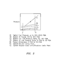
Figure 2 is a graphical representation of actuator pressures for a fuel system and lubrication system driven actuators. -
Figure 1 schematically illustrates a gasturbine engine system 20 which includes agas turbine engine 22 in fluid communication with afuel system 24 and alubrication system 26. While a gasturbine engine system 20 typically utilized for aircraft propulsion is schematically illustrated in the disclosed non-limiting embodiment, it should be understood that the disclosure is applicable to other gas turbine engine configurations, vehicles and gas turbines for power generation. - The
fuel system 24 generally includes afuel tank 28, lowpressure fuel pump 30, aheat exchanger 32, afilter system 34, a highpressure fuel pump 36 andcontrol 36c which supplies a burn flow of fuel to acombustor 22C of thegas turbine engine 22. Although particular components are illustrated in the disclosed, non-limiting embodiment it should be understood other fuel system components may alternatively or additionally be provided. - The
fuel system 24 supplies fuel typically in quantities that are in excess of that required to fuel thegas turbine engine 22 such that excess fuel is recirculated throughline 38. Even with recirculation, thefuel system 24 need only provides fuel quantities to accommodate the fuel burn operation, as thelubrication system 26 provides hydraulic power for engine actuation operations. The size and minimum pressure of thepumps - The
lubrication system 26 generally includes alubricant tank 40, a variableoutput lubricant pump 42, theheat exchanger 32, afilter system 44, ascavenge pump 46, a centrifugal air/lubricant separator 48 driven by amotor 50 and anoptional scrubber system 52. Theheat exchanger 32 may be an air or fuel cooled system and may alternatively or additionally include a multiple of heat exchangers in a distributed arrangement. Although particular components are illustrated in the disclosed, non-limiting embodiment it should be understood other lubrication system components may alternatively or additionally be provided. - The
lubrication system 26 supplies lubricant to alubricant distribution system 54 which communicates lubricant toengine components 56 such asbearing components 56A, 56B, 56C. It should be understood that other components may alternatively or additionally receive lubricant from thelubricant distribution system 54. From thecomponents 56, the lubricant is scavenged within ascavenge system 58 by thescavenge pump 46. - The centrifugal air/
lubricant separator 48 is selectively driven by themotor 50 to remove air from the scavenged lubricant. Themotor 50 is controlled to drive the centrifugal air/lubricant separator 48 to optimize air separation such that thelubricant tank 40 may be of a relatively small size as compared to conventional lubricant tanks which may be relatively larger to permit increased residence time for the lubricant to settle and allow air to escape from the lubricant. - The centrifugal air/
lubricant separator 48 separates lubricant from the air and returns the lubricant to thelubrication tank 40 and dumps the air overboard. Thescrubber system 52 may additionally be utilized to scrub the overboard air for any residual lubricant. - The
lubrication system 26 selectively supplies lubricant to anactuator system 60 which includes a multiple of actuators such as a high pressurestator vane actuator 60A, a mid stage bleedactuator 60B, low pressurestator vane actuator 60C and others. It should be understood that other actuators, variable geometry and fluid driven systems may alternatively or additionally be driven by thelubricant system 26. - The variable
output lubricant pump 42 utilizes acontrol 42c to optimize lubricant communication efficiency to assure adequate pressure is provided dependent on, for example, the number or actuators which are in operation. That is, the variableoutput lubricant pump 42 may operate in response to thecontrol 42c at one speed to supply a desired lubricant output to thelubricant distribution system 54 and may operate at a second higher speed to supply the desired lubricant output to thelubricant distribution system 54 as well as supply theactuator system 60. The variableoutput lubricant pump 42 may alternatively be gearbox driven so speed is a function of engine speed and variable output is set by pump displacement or may be a variable speed electric type. - The
controllers pressure fuel pump 36, variableoutput lubricant pump 42 andmotor 50. Thecontrollers controllers - Actuation return lubricant from the
actuator system 60 can be returned throughreturn line 62 upstream of the variableoutput lubricant pump 42. Alternatively, the return lubricant from theactuator system 60 may be returned to thelubricant tank 40. - Typical fuel supply pressures vary between approximately 200 to 2000 PSIA (1378951 to 13789514 Pa) while typical lubricant supply pressures vary between approximately 100 to 400 PSIA (2757902 to 27579029 Pa) (
Figure 2 ). When driven by thelubrication system 26, theactuator system 60 need only be designed for the lower pressures and lower range of pressures which advantageously improves actuator force balance, maximum output limits, structural wall size and material combinations. The reduction in minimum to maximum pressure range provided by thelubrication system 26 provides a relatively close match between ambient actuator pressure and lubricant sump pressure which facilitates a reduced actuator size, lighter actuator design, or combination thereof. - The
lubrication system 26 drivenactuator system 60 further permits relatively lighter weight actuators manufactured from materials such as aluminum and composites, as theactuator system 60 operates at lower pressures and are not subject to significant waste power at maximum pressure operations such as takeoff. That is, the lower pressure of thelubrication system 26 does not require pressure toping features typically required with fueldraulics to prevent high output loads at maximum fuel flow conditions. Also, potential transient shortfalls are more readily absorbed by thelubrication system 26 as compared to thefuel system 24 which facilities transient sizing optimization. - It should be understood that like reference numerals identify corresponding or similar elements throughout the several drawings. It should also be understood that although a particular component arrangement is disclosed in the illustrated embodiment, other arrangements will benefit herefrom.
- Although particular step sequences are shown, described, and claimed, it should be understood that steps may be performed in any order, separated or combined unless otherwise indicated and will still benefit from the present disclosure.
- The foregoing description is exemplary rather than defined by the limitations within. Various non-limiting embodiments are disclosed herein, however, one of ordinary skill in the art would recognize that various modifications and variations in light of the above teachings will fall within the scope of the appended claims. It is therefore to be understood that within the scope of the appended claims, the disclosure may be practiced other than as specifically described. For that reason the appended claims should be studied to determine true scope and content.
Claims (15)
- A lubrication system (26) for a gas turbine engine (22) comprising:an actuator system (60); anda variable output lubricant pump (42) operable to supply lubricant to said actuator system.
- The lubrication system as recited in claim 1, wherein said actuator system provides variable engine geometries.
- The lubrication system as recited in claim 1 or 2, wherein said actuator system includes a stator vane actuator.
- The lubrication system as recited in claim 1, 2 or 3, wherein said variable output lubricant pump is operable to supply lubricant to a lubricant distribution system (54).
- The lubrication system as recited in claim 4, further comprising a scavenge system (58) in fluid communication with said lubricant distribution system.
- The lubrication system as recited in claim 5, wherein said lubricant distribution system communicates lubricant within said gas turbine engine to a bearing system.
- The lubrication system as recited in claim 5 or 6, wherein said scavenge system includes a centrifugal air/lubricant separator (48) selectively driven by a motor.
- The lubrication system as recited in claim 7, wherein said motor is operated to minimize a residence time within a lubricant tank downstream of said centrifugal air/lubricant separator.
- A gas turbine engine system (20) comprising:a gas turbine engine (22);a lubricant distribution system for said gas turbine engine;a fuel system operable to supply a burn flow to a combustor (22C) of said gas turbine engine; anda lubrication system (26) as recited in claim 1,wherein said actuator system provides variable engine geometries; andwherein said lubrication system is operable to supply lubricant to said actuator system and said lubricant distribution system.
- The gas turbine engine system as recited in claim 9, wherein said lubricant distribution system communicates lubricant within said gas turbine engine to a lubricant distribution system.
- The gas turbine engine system as recited in claim 9 or 10, wherein said fuel system is operable to supply only said burn flow.
- The gas turbine engine system as recited in claim 9, 10 or 11, further comprising a scavenge system in fluid communication with said lubricant distribution system.
- The gas turbine engine system as recited in claim 9, 10, 11 or 12, wherein said actuator system includes an actuation return which communicates lubricant from downstream of said actuation system to upstream of a variable output lubricant pump of said lubricant system; preferably wherein said actuator system comprises a stator vane actuator.
- A method of actuating variable engine geometries within a gas turbine engine (22) comprising:supplying lubricant to a gas turbine engine actuator system (60) to provide variable engine geometries; andsupplying fuel as a burn flow only.
- The method as recited in claim 14, wherein said variable engine geometries are controlled by a stator vane actuator.
Priority Applications (1)
| Application Number | Priority Date | Filing Date | Title |
|---|---|---|---|
| EP15183619.4A EP2980364B1 (en) | 2010-06-15 | 2011-06-09 | Lubrication driven gas turbine engine actuation system |
Applications Claiming Priority (1)
| Application Number | Priority Date | Filing Date | Title |
|---|---|---|---|
| US12/815,456 US9151180B2 (en) | 2010-06-15 | 2010-06-15 | Lubrication driven gas turbine engine actuation system |
Related Child Applications (2)
| Application Number | Title | Priority Date | Filing Date |
|---|---|---|---|
| EP15183619.4A Division-Into EP2980364B1 (en) | 2010-06-15 | 2011-06-09 | Lubrication driven gas turbine engine actuation system |
| EP15183619.4A Division EP2980364B1 (en) | 2010-06-15 | 2011-06-09 | Lubrication driven gas turbine engine actuation system |
Publications (2)
| Publication Number | Publication Date |
|---|---|
| EP2426320A1 true EP2426320A1 (en) | 2012-03-07 |
| EP2426320B1 EP2426320B1 (en) | 2015-11-25 |
Family
ID=44583941
Family Applications (2)
| Application Number | Title | Priority Date | Filing Date |
|---|---|---|---|
| EP15183619.4A Active EP2980364B1 (en) | 2010-06-15 | 2011-06-09 | Lubrication driven gas turbine engine actuation system |
| EP11169357.8A Active EP2426320B1 (en) | 2010-06-15 | 2011-06-09 | Lubrication driven gas turbine engine actuation system |
Family Applications Before (1)
| Application Number | Title | Priority Date | Filing Date |
|---|---|---|---|
| EP15183619.4A Active EP2980364B1 (en) | 2010-06-15 | 2011-06-09 | Lubrication driven gas turbine engine actuation system |
Country Status (2)
| Country | Link |
|---|---|
| US (1) | US9151180B2 (en) |
| EP (2) | EP2980364B1 (en) |
Families Citing this family (14)
| Publication number | Priority date | Publication date | Assignee | Title |
|---|---|---|---|---|
| RU2353787C1 (en) * | 2007-09-06 | 2009-04-27 | Открытое акционерное общество "Российские железные дороги" (ОАО "РЖД") | Gas-turbine plant |
| ITFI20120047A1 (en) * | 2012-03-08 | 2013-09-09 | Nuovo Pignone Srl | "GAS TURBINE WITH PRIMARY AND SECONDARY LUBRICATING OIL COOLER" |
| WO2015147948A2 (en) * | 2014-01-20 | 2015-10-01 | United Technologies Corporation | Geared gas turbine engine with reduced oil tank size |
| US10066507B1 (en) * | 2015-02-10 | 2018-09-04 | United Technologies Corporation | Turbine engine lubrication system with wash flow filter |
| US10436168B2 (en) * | 2015-07-08 | 2019-10-08 | Ge Aviation Systems Llc | Air starter and methods for determining hydrostatic lock |
| US10428816B2 (en) | 2016-10-24 | 2019-10-01 | Hamilton Sundstrand Corporation | Variable speed multi-stage pump |
| US10513985B2 (en) * | 2016-10-25 | 2019-12-24 | Pratt & Whitney Canada Corp. | Fire mitigation system for gas turbine engine |
| US11492970B2 (en) | 2020-12-21 | 2022-11-08 | General Electric Company | Thermal management system with fuel cooling |
| US11560239B2 (en) | 2020-12-21 | 2023-01-24 | General Electric Company | Regenerative thermal management system |
| US11761344B1 (en) | 2022-04-19 | 2023-09-19 | General Electric Company | Thermal management system |
| US11702985B1 (en) | 2022-04-19 | 2023-07-18 | General Electric Company | Thermal management system |
| US11905884B1 (en) | 2022-09-16 | 2024-02-20 | General Electric Company | Hydrogen fuel system for a gas turbine engine |
| US11873768B1 (en) | 2022-09-16 | 2024-01-16 | General Electric Company | Hydrogen fuel system for a gas turbine engine |
| US11898495B1 (en) | 2022-09-16 | 2024-02-13 | General Electric Company | Hydrogen fuel system for a gas turbine engine |
Citations (3)
| Publication number | Priority date | Publication date | Assignee | Title |
|---|---|---|---|---|
| US5159808A (en) * | 1990-07-09 | 1992-11-03 | General Electric Company | Gas turbine engine fuel and hydraulic fluid pumping system |
| EP2071140A2 (en) * | 2007-12-12 | 2009-06-17 | United Technologies Corporation | On-demand lubrication system and method for improved flow management and containment |
| FR2925594A1 (en) * | 2007-12-20 | 2009-06-26 | Hispano Suiza Sa | SYSTEM FOR CONTROLLING A TURBOMACHINE |
Family Cites Families (47)
| Publication number | Priority date | Publication date | Assignee | Title |
|---|---|---|---|---|
| US2761387A (en) | 1950-09-25 | 1956-09-04 | Gen Motors Corp | Fuel system |
| US2780172A (en) | 1952-04-26 | 1957-02-05 | United Aircraft Corp | Dual fuel pump |
| US3026929A (en) | 1954-03-17 | 1962-03-27 | Chandler Evans Corp | Compound centrifugal and gear fuel pump |
| US3011308A (en) | 1956-01-04 | 1961-12-05 | Thompson Ramo Wooldridge Inc | Fuel and afterburner pump system |
| US3357178A (en) * | 1966-05-06 | 1967-12-12 | Bendix Corp | Actuator for turbine stator blades |
| GB1508212A (en) * | 1975-02-10 | 1978-04-19 | Rolls Royce | Apparatus for separating suspension of liquids in gas |
| US4171611A (en) * | 1975-08-07 | 1979-10-23 | Motoren- Und Turbinen-Union Munchen Gmbh | Vehicular gas turbine system |
| US4708030A (en) | 1985-03-18 | 1987-11-24 | Sundstrand Corporation | Multi-range starter-generator drive |
| US5028803A (en) | 1989-03-22 | 1991-07-02 | Sundstrand Corporation | Integrated drive generator system with direct motor drive prime mover starting |
| US5241814A (en) | 1989-04-06 | 1993-09-07 | Rolls-Royce Plc | Management of heat generated by aircraft gas turbine installations |
| US5121599A (en) * | 1991-02-21 | 1992-06-16 | United Technologies Corporation | Oil filtration system and method |
| DE4131913A1 (en) | 1991-09-25 | 1993-04-08 | Mtu Muenchen Gmbh | COOLING DEVICE FOR HYPERSONIC AIR JET ENGINES |
| US5220793A (en) * | 1992-06-29 | 1993-06-22 | United Technologies Corporation | Centrifugal pump fuel system |
| US5349811A (en) * | 1992-12-16 | 1994-09-27 | Avco Corporation | Pulsed fuel injection system for reducing NOx emissions |
| DE69427384T2 (en) | 1993-03-16 | 2002-05-23 | Allied Signal Inc | Torque control for a gas turbine starter |
| US5365732A (en) * | 1993-04-19 | 1994-11-22 | General Electric Company | Retrofittable trim system for fuel-air optimization in cannular gas turbine combustors |
| US5414992A (en) | 1993-08-06 | 1995-05-16 | United Technologies Corporation | Aircraft cooling method |
| US5575159A (en) | 1995-06-02 | 1996-11-19 | Dittell; Edward W. | Heat energy transfer system |
| US5694764A (en) * | 1995-09-18 | 1997-12-09 | Sundstrand Corporation | Fuel pump assist for engine starting |
| US6182435B1 (en) | 1997-06-05 | 2001-02-06 | Hamilton Sundstrand Corporation | Thermal and energy management method and apparatus for an aircraft |
| GB9727157D0 (en) | 1997-12-24 | 1998-02-25 | Lucas Ind Plc | Fuel system for a gas turbine engine |
| US6286299B1 (en) * | 1999-04-26 | 2001-09-11 | General Electric Co. | Gas turbine combined lift/hydraulic system |
| US6263864B1 (en) | 2000-06-19 | 2001-07-24 | The United States Of America As Represented By The Secretary Of The Air Force | Alternate fuel system for internal combustion engines |
| FR2842564B1 (en) * | 2002-07-17 | 2006-01-21 | Snecma Moteurs | ASSISTANCE AND RELIEF FOR THE ELECTRICAL DRIVING OF ACCESSORIES IN A TURBOMOTEUR |
| GB0218849D0 (en) * | 2002-08-14 | 2002-09-25 | Rolls Royce Plc | Lubrication system for gas turbine engine |
| US7007452B1 (en) | 2003-06-13 | 2006-03-07 | Woodward Governor Company | Fuel system for a gas turbine engine |
| US7342763B2 (en) | 2003-06-13 | 2008-03-11 | Tdg Aerospace, Inc. | Fuel system safety device for run-dry conditions |
| US20050084388A1 (en) * | 2003-07-17 | 2005-04-21 | Hayes Alan E. | Positive displacement liquid pump |
| US7350372B2 (en) * | 2003-10-27 | 2008-04-01 | Wells David N | System and method for selective heating and cooling |
| US7118336B2 (en) * | 2003-12-19 | 2006-10-10 | Pratt & Whitney Canada Corp. | Pressurized oil supply for propeller engine system |
| US7260926B2 (en) | 2004-01-20 | 2007-08-28 | United Technologies Corporation | Thermal management system for an aircraft |
| US7063734B2 (en) * | 2004-03-23 | 2006-06-20 | Pratt & Whitney Canada Corp. | Air/oil separation system and method |
| US7610760B2 (en) | 2004-03-29 | 2009-11-03 | Argo-Tech Corporation | Two-displacement setting variable displacement pump used as engine over-thrust protection with fuel system thermal benefit |
| US7377110B2 (en) * | 2004-03-31 | 2008-05-27 | United Technologies Corporation | Deoiler for a lubrication system |
| US7185496B2 (en) | 2004-07-12 | 2007-03-06 | Honeywell International, Inc. | Synchronizing stationary clutch of compression braking with a two spool gas turbine engine |
| US7484522B2 (en) | 2004-10-19 | 2009-02-03 | Honeywell International Inc. | Method to control starter/generator cooling fuel flow during engine starting |
| JP4509742B2 (en) * | 2004-11-04 | 2010-07-21 | 株式会社日立製作所 | Gas turbine power generation equipment |
| GB0425785D0 (en) | 2004-11-24 | 2004-12-22 | Goodrich Control Sys Ltd | Fuel supply system |
| GB0508126D0 (en) | 2005-04-22 | 2005-06-01 | Goodrich Control Sys Ltd | Fuel system |
| US7434406B2 (en) | 2005-05-10 | 2008-10-14 | Honeywell International Inc. | Drive for using a direct driven generator to start a counter-rotating multi-spool gas turbine engine |
| US7401461B2 (en) | 2005-05-27 | 2008-07-22 | Honeywell International Inc. | Reduced-weight fuel system for gas turbine engine, gas turbine engine having a reduced-weight fuel system, and method of providing fuel to a gas turbine engine using a reduced-weight fuel system |
| US7537646B2 (en) | 2005-10-11 | 2009-05-26 | United Technologies Corporation | Fuel system and method of reducing emission |
| US7908840B2 (en) * | 2006-11-29 | 2011-03-22 | United Technologies Corporation | Turbine engine with integrated generator having shared lubrication system |
| US20090313999A1 (en) * | 2008-05-13 | 2009-12-24 | Scott Hunter | Method and apparatus for controlling fuel in a gas turbine engine |
| US7984606B2 (en) * | 2008-11-03 | 2011-07-26 | Propulsion, Gas Turbine, And Energy Evaluations, Llc | Systems and methods for thermal management in a gas turbine powerplant |
| US8572974B2 (en) * | 2009-07-31 | 2013-11-05 | Hamilton Sundstrand Corporation | Variable speed and displacement electric fluid delivery system for a gas turbine engine |
| US8196408B2 (en) * | 2009-10-09 | 2012-06-12 | General Electric Company | System and method for distributing fuel in a turbomachine |
-
2010
- 2010-06-15 US US12/815,456 patent/US9151180B2/en active Active
-
2011
- 2011-06-09 EP EP15183619.4A patent/EP2980364B1/en active Active
- 2011-06-09 EP EP11169357.8A patent/EP2426320B1/en active Active
Patent Citations (3)
| Publication number | Priority date | Publication date | Assignee | Title |
|---|---|---|---|---|
| US5159808A (en) * | 1990-07-09 | 1992-11-03 | General Electric Company | Gas turbine engine fuel and hydraulic fluid pumping system |
| EP2071140A2 (en) * | 2007-12-12 | 2009-06-17 | United Technologies Corporation | On-demand lubrication system and method for improved flow management and containment |
| FR2925594A1 (en) * | 2007-12-20 | 2009-06-26 | Hispano Suiza Sa | SYSTEM FOR CONTROLLING A TURBOMACHINE |
Also Published As
| Publication number | Publication date |
|---|---|
| US9151180B2 (en) | 2015-10-06 |
| EP2426320B1 (en) | 2015-11-25 |
| EP2980364B1 (en) | 2018-08-08 |
| EP2980364A1 (en) | 2016-02-03 |
| US20110302903A1 (en) | 2011-12-15 |
Similar Documents
| Publication | Publication Date | Title |
|---|---|---|
| EP2426320B1 (en) | Lubrication driven gas turbine engine actuation system | |
| EP3421760B1 (en) | Hybrid-electricpropulsion system for an aircraft | |
| EP2584174B1 (en) | Windmill operation of a gas turbine engine | |
| EP2784270B1 (en) | Fuel and actuation system for gas turbine engine and a corresponding method. | |
| US7118336B2 (en) | Pressurized oil supply for propeller engine system | |
| RU2352800C2 (en) | Method and system to generate power to drive engine auxiliary components | |
| EP2584173B1 (en) | Gas Turbine Engine | |
| EP2584172B1 (en) | Constant speed transmission for gas turbine engine | |
| EP1726879B1 (en) | Reduced-weight fuel system for a gas turbine engine, gas turbine engine including such a system, and method of providing fuel to such a gas turbine engine | |
| EP2065585B1 (en) | Gas turbine engine with pylon mounted accessory drive | |
| US20110023444A1 (en) | Variable speed and displacement electric fluid delivery system for a gas turbine engine | |
| EP2584175B2 (en) | Operation of a gas turbine | |
| EP2584168A2 (en) | Integrated thermal system for a gas turbine engine | |
| EP2584169A2 (en) | Integrated thermal management system and environment control system for a gas turbine engine | |
| EP3260688A1 (en) | Compartment cooling for a gas turbine engine | |
| EP2407660B1 (en) | Auxiliary hydraulic power generation system | |
| GB2455901A (en) | An auxiliary circuit operating actuators and having a dedicated pump suitable for turbomachinery | |
| EP2929164B1 (en) | Gas turbine engine with a low speed spool driven pump arrangement | |
| EP3851654A1 (en) | Dual pump unit with boost pump | |
| EP3744636A1 (en) | Air system of multi-engine aircraft | |
| EP4151842A1 (en) | Aircraft power plant | |
| US20220316361A1 (en) | Oil tank for aircraft engine | |
| CN115991285A (en) | Hydrogen fuel system |
Legal Events
| Date | Code | Title | Description |
|---|---|---|---|
| AK | Designated contracting states |
Kind code of ref document: A1 Designated state(s): AL AT BE BG CH CY CZ DE DK EE ES FI FR GB GR HR HU IE IS IT LI LT LU LV MC MK MT NL NO PL PT RO RS SE SI SK SM TR |
|
| AX | Request for extension of the european patent |
Extension state: BA ME |
|
| PUAI | Public reference made under article 153(3) epc to a published international application that has entered the european phase |
Free format text: ORIGINAL CODE: 0009012 |
|
| 17P | Request for examination filed |
Effective date: 20120907 |
|
| 17Q | First examination report despatched |
Effective date: 20150109 |
|
| REG | Reference to a national code |
Ref country code: DE Ref legal event code: R079 Ref document number: 602011021574 Country of ref document: DE Free format text: PREVIOUS MAIN CLASS: F01D0017120000 Ipc: F01D0025200000 |
|
| GRAP | Despatch of communication of intention to grant a patent |
Free format text: ORIGINAL CODE: EPIDOSNIGR1 |
|
| RIC1 | Information provided on ipc code assigned before grant |
Ipc: F01D 17/16 20060101ALI20150529BHEP Ipc: F02C 7/06 20060101ALI20150529BHEP Ipc: F01D 25/20 20060101AFI20150529BHEP Ipc: F01D 25/18 20060101ALI20150529BHEP |
|
| INTG | Intention to grant announced |
Effective date: 20150707 |
|
| GRAS | Grant fee paid |
Free format text: ORIGINAL CODE: EPIDOSNIGR3 |
|
| GRAA | (expected) grant |
Free format text: ORIGINAL CODE: 0009210 |
|
| AK | Designated contracting states |
Kind code of ref document: B1 Designated state(s): AL AT BE BG CH CY CZ DE DK EE ES FI FR GB GR HR HU IE IS IT LI LT LU LV MC MK MT NL NO PL PT RO RS SE SI SK SM TR |
|
| REG | Reference to a national code |
Ref country code: GB Ref legal event code: FG4D |
|
| REG | Reference to a national code |
Ref country code: CH Ref legal event code: EP |
|
| REG | Reference to a national code |
Ref country code: AT Ref legal event code: REF Ref document number: 762729 Country of ref document: AT Kind code of ref document: T Effective date: 20151215 |
|
| REG | Reference to a national code |
Ref country code: IE Ref legal event code: FG4D |
|
| REG | Reference to a national code |
Ref country code: DE Ref legal event code: R096 Ref document number: 602011021574 Country of ref document: DE |
|
| REG | Reference to a national code |
Ref country code: LT Ref legal event code: MG4D |
|
| REG | Reference to a national code |
Ref country code: NL Ref legal event code: MP Effective date: 20160225 |
|
| REG | Reference to a national code |
Ref country code: AT Ref legal event code: MK05 Ref document number: 762729 Country of ref document: AT Kind code of ref document: T Effective date: 20151125 |
|
| PG25 | Lapsed in a contracting state [announced via postgrant information from national office to epo] |
Ref country code: NO Free format text: LAPSE BECAUSE OF FAILURE TO SUBMIT A TRANSLATION OF THE DESCRIPTION OR TO PAY THE FEE WITHIN THE PRESCRIBED TIME-LIMIT Effective date: 20160225 Ref country code: HR Free format text: LAPSE BECAUSE OF FAILURE TO SUBMIT A TRANSLATION OF THE DESCRIPTION OR TO PAY THE FEE WITHIN THE PRESCRIBED TIME-LIMIT Effective date: 20151125 Ref country code: LT Free format text: LAPSE BECAUSE OF FAILURE TO SUBMIT A TRANSLATION OF THE DESCRIPTION OR TO PAY THE FEE WITHIN THE PRESCRIBED TIME-LIMIT Effective date: 20151125 Ref country code: IS Free format text: LAPSE BECAUSE OF FAILURE TO SUBMIT A TRANSLATION OF THE DESCRIPTION OR TO PAY THE FEE WITHIN THE PRESCRIBED TIME-LIMIT Effective date: 20160325 Ref country code: NL Free format text: LAPSE BECAUSE OF FAILURE TO SUBMIT A TRANSLATION OF THE DESCRIPTION OR TO PAY THE FEE WITHIN THE PRESCRIBED TIME-LIMIT Effective date: 20151125 Ref country code: ES Free format text: LAPSE BECAUSE OF FAILURE TO SUBMIT A TRANSLATION OF THE DESCRIPTION OR TO PAY THE FEE WITHIN THE PRESCRIBED TIME-LIMIT Effective date: 20151125 |
|
| REG | Reference to a national code |
Ref country code: FR Ref legal event code: PLFP Year of fee payment: 6 |
|
| PG25 | Lapsed in a contracting state [announced via postgrant information from national office to epo] |
Ref country code: LV Free format text: LAPSE BECAUSE OF FAILURE TO SUBMIT A TRANSLATION OF THE DESCRIPTION OR TO PAY THE FEE WITHIN THE PRESCRIBED TIME-LIMIT Effective date: 20151125 Ref country code: PT Free format text: LAPSE BECAUSE OF FAILURE TO SUBMIT A TRANSLATION OF THE DESCRIPTION OR TO PAY THE FEE WITHIN THE PRESCRIBED TIME-LIMIT Effective date: 20160325 Ref country code: PL Free format text: LAPSE BECAUSE OF FAILURE TO SUBMIT A TRANSLATION OF THE DESCRIPTION OR TO PAY THE FEE WITHIN THE PRESCRIBED TIME-LIMIT Effective date: 20151125 Ref country code: SE Free format text: LAPSE BECAUSE OF FAILURE TO SUBMIT A TRANSLATION OF THE DESCRIPTION OR TO PAY THE FEE WITHIN THE PRESCRIBED TIME-LIMIT Effective date: 20151125 Ref country code: GR Free format text: LAPSE BECAUSE OF FAILURE TO SUBMIT A TRANSLATION OF THE DESCRIPTION OR TO PAY THE FEE WITHIN THE PRESCRIBED TIME-LIMIT Effective date: 20160226 Ref country code: RS Free format text: LAPSE BECAUSE OF FAILURE TO SUBMIT A TRANSLATION OF THE DESCRIPTION OR TO PAY THE FEE WITHIN THE PRESCRIBED TIME-LIMIT Effective date: 20151125 Ref country code: AT Free format text: LAPSE BECAUSE OF FAILURE TO SUBMIT A TRANSLATION OF THE DESCRIPTION OR TO PAY THE FEE WITHIN THE PRESCRIBED TIME-LIMIT Effective date: 20151125 Ref country code: FI Free format text: LAPSE BECAUSE OF FAILURE TO SUBMIT A TRANSLATION OF THE DESCRIPTION OR TO PAY THE FEE WITHIN THE PRESCRIBED TIME-LIMIT Effective date: 20151125 |
|
| PG25 | Lapsed in a contracting state [announced via postgrant information from national office to epo] |
Ref country code: CZ Free format text: LAPSE BECAUSE OF FAILURE TO SUBMIT A TRANSLATION OF THE DESCRIPTION OR TO PAY THE FEE WITHIN THE PRESCRIBED TIME-LIMIT Effective date: 20151125 Ref country code: IT Free format text: LAPSE BECAUSE OF FAILURE TO SUBMIT A TRANSLATION OF THE DESCRIPTION OR TO PAY THE FEE WITHIN THE PRESCRIBED TIME-LIMIT Effective date: 20151125 |
|
| REG | Reference to a national code |
Ref country code: DE Ref legal event code: R097 Ref document number: 602011021574 Country of ref document: DE |
|
| PG25 | Lapsed in a contracting state [announced via postgrant information from national office to epo] |
Ref country code: DK Free format text: LAPSE BECAUSE OF FAILURE TO SUBMIT A TRANSLATION OF THE DESCRIPTION OR TO PAY THE FEE WITHIN THE PRESCRIBED TIME-LIMIT Effective date: 20151125 Ref country code: SK Free format text: LAPSE BECAUSE OF FAILURE TO SUBMIT A TRANSLATION OF THE DESCRIPTION OR TO PAY THE FEE WITHIN THE PRESCRIBED TIME-LIMIT Effective date: 20151125 Ref country code: EE Free format text: LAPSE BECAUSE OF FAILURE TO SUBMIT A TRANSLATION OF THE DESCRIPTION OR TO PAY THE FEE WITHIN THE PRESCRIBED TIME-LIMIT Effective date: 20151125 Ref country code: SM Free format text: LAPSE BECAUSE OF FAILURE TO SUBMIT A TRANSLATION OF THE DESCRIPTION OR TO PAY THE FEE WITHIN THE PRESCRIBED TIME-LIMIT Effective date: 20151125 Ref country code: RO Free format text: LAPSE BECAUSE OF FAILURE TO SUBMIT A TRANSLATION OF THE DESCRIPTION OR TO PAY THE FEE WITHIN THE PRESCRIBED TIME-LIMIT Effective date: 20151125 |
|
| PLBE | No opposition filed within time limit |
Free format text: ORIGINAL CODE: 0009261 |
|
| STAA | Information on the status of an ep patent application or granted ep patent |
Free format text: STATUS: NO OPPOSITION FILED WITHIN TIME LIMIT |
|
| 26N | No opposition filed |
Effective date: 20160826 |
|
| PG25 | Lapsed in a contracting state [announced via postgrant information from national office to epo] |
Ref country code: SI Free format text: LAPSE BECAUSE OF FAILURE TO SUBMIT A TRANSLATION OF THE DESCRIPTION OR TO PAY THE FEE WITHIN THE PRESCRIBED TIME-LIMIT Effective date: 20151125 |
|
| PG25 | Lapsed in a contracting state [announced via postgrant information from national office to epo] |
Ref country code: BE Free format text: LAPSE BECAUSE OF FAILURE TO SUBMIT A TRANSLATION OF THE DESCRIPTION OR TO PAY THE FEE WITHIN THE PRESCRIBED TIME-LIMIT Effective date: 20151125 |
|
| PG25 | Lapsed in a contracting state [announced via postgrant information from national office to epo] |
Ref country code: MC Free format text: LAPSE BECAUSE OF FAILURE TO SUBMIT A TRANSLATION OF THE DESCRIPTION OR TO PAY THE FEE WITHIN THE PRESCRIBED TIME-LIMIT Effective date: 20151125 |
|
| REG | Reference to a national code |
Ref country code: CH Ref legal event code: PL |
|
| REG | Reference to a national code |
Ref country code: IE Ref legal event code: MM4A |
|
| PG25 | Lapsed in a contracting state [announced via postgrant information from national office to epo] |
Ref country code: LI Free format text: LAPSE BECAUSE OF NON-PAYMENT OF DUE FEES Effective date: 20160630 Ref country code: CH Free format text: LAPSE BECAUSE OF NON-PAYMENT OF DUE FEES Effective date: 20160630 |
|
| REG | Reference to a national code |
Ref country code: FR Ref legal event code: PLFP Year of fee payment: 7 |
|
| PG25 | Lapsed in a contracting state [announced via postgrant information from national office to epo] |
Ref country code: IE Free format text: LAPSE BECAUSE OF NON-PAYMENT OF DUE FEES Effective date: 20160609 |
|
| REG | Reference to a national code |
Ref country code: FR Ref legal event code: PLFP Year of fee payment: 8 |
|
| PG25 | Lapsed in a contracting state [announced via postgrant information from national office to epo] |
Ref country code: CY Free format text: LAPSE BECAUSE OF FAILURE TO SUBMIT A TRANSLATION OF THE DESCRIPTION OR TO PAY THE FEE WITHIN THE PRESCRIBED TIME-LIMIT Effective date: 20151125 Ref country code: HU Free format text: LAPSE BECAUSE OF FAILURE TO SUBMIT A TRANSLATION OF THE DESCRIPTION OR TO PAY THE FEE WITHIN THE PRESCRIBED TIME-LIMIT; INVALID AB INITIO Effective date: 20110609 |
|
| PG25 | Lapsed in a contracting state [announced via postgrant information from national office to epo] |
Ref country code: LU Free format text: LAPSE BECAUSE OF NON-PAYMENT OF DUE FEES Effective date: 20160609 Ref country code: MK Free format text: LAPSE BECAUSE OF FAILURE TO SUBMIT A TRANSLATION OF THE DESCRIPTION OR TO PAY THE FEE WITHIN THE PRESCRIBED TIME-LIMIT Effective date: 20151125 Ref country code: TR Free format text: LAPSE BECAUSE OF FAILURE TO SUBMIT A TRANSLATION OF THE DESCRIPTION OR TO PAY THE FEE WITHIN THE PRESCRIBED TIME-LIMIT Effective date: 20151125 Ref country code: MT Free format text: LAPSE BECAUSE OF NON-PAYMENT OF DUE FEES Effective date: 20160630 |
|
| PG25 | Lapsed in a contracting state [announced via postgrant information from national office to epo] |
Ref country code: BG Free format text: LAPSE BECAUSE OF FAILURE TO SUBMIT A TRANSLATION OF THE DESCRIPTION OR TO PAY THE FEE WITHIN THE PRESCRIBED TIME-LIMIT Effective date: 20151125 |
|
| PG25 | Lapsed in a contracting state [announced via postgrant information from national office to epo] |
Ref country code: AL Free format text: LAPSE BECAUSE OF FAILURE TO SUBMIT A TRANSLATION OF THE DESCRIPTION OR TO PAY THE FEE WITHIN THE PRESCRIBED TIME-LIMIT Effective date: 20151125 |
|
| REG | Reference to a national code |
Ref country code: DE Ref legal event code: R082 Ref document number: 602011021574 Country of ref document: DE |
|
| P01 | Opt-out of the competence of the unified patent court (upc) registered |
Effective date: 20230522 |
|
| PGFP | Annual fee paid to national office [announced via postgrant information from national office to epo] |
Ref country code: FR Payment date: 20230523 Year of fee payment: 13 Ref country code: DE Payment date: 20230523 Year of fee payment: 13 |
|
| PGFP | Annual fee paid to national office [announced via postgrant information from national office to epo] |
Ref country code: GB Payment date: 20230523 Year of fee payment: 13 |