EP2425985B1 - Thermal imagable waterless lithographic member - Google Patents
Thermal imagable waterless lithographic member Download PDFInfo
- Publication number
- EP2425985B1 EP2425985B1 EP11180254.2A EP11180254A EP2425985B1 EP 2425985 B1 EP2425985 B1 EP 2425985B1 EP 11180254 A EP11180254 A EP 11180254A EP 2425985 B1 EP2425985 B1 EP 2425985B1
- Authority
- EP
- European Patent Office
- Prior art keywords
- layer
- printing
- imaging layer
- printing member
- substrate
- Prior art date
- Legal status (The legal status is an assumption and is not a legal conclusion. Google has not performed a legal analysis and makes no representation as to the accuracy of the status listed.)
- Not-in-force
Links
Images


Classifications
-
- B—PERFORMING OPERATIONS; TRANSPORTING
- B41—PRINTING; LINING MACHINES; TYPEWRITERS; STAMPS
- B41N—PRINTING PLATES OR FOILS; MATERIALS FOR SURFACES USED IN PRINTING MACHINES FOR PRINTING, INKING, DAMPING, OR THE LIKE; PREPARING SUCH SURFACES FOR USE AND CONSERVING THEM
- B41N1/00—Printing plates or foils; Materials therefor
- B41N1/003—Printing plates or foils; Materials therefor with ink abhesive means or abhesive forming means, such as abhesive siloxane or fluoro compounds, e.g. for dry lithographic printing
-
- B—PERFORMING OPERATIONS; TRANSPORTING
- B41—PRINTING; LINING MACHINES; TYPEWRITERS; STAMPS
- B41C—PROCESSES FOR THE MANUFACTURE OR REPRODUCTION OF PRINTING SURFACES
- B41C1/00—Forme preparation
- B41C1/10—Forme preparation for lithographic printing; Master sheets for transferring a lithographic image to the forme
- B41C1/1008—Forme preparation for lithographic printing; Master sheets for transferring a lithographic image to the forme by removal or destruction of lithographic material on the lithographic support, e.g. by laser or spark ablation; by the use of materials rendered soluble or insoluble by heat exposure, e.g. by heat produced from a light to heat transforming system; by on-the-press exposure or on-the-press development, e.g. by the fountain of photolithographic materials
- B41C1/1033—Forme preparation for lithographic printing; Master sheets for transferring a lithographic image to the forme by removal or destruction of lithographic material on the lithographic support, e.g. by laser or spark ablation; by the use of materials rendered soluble or insoluble by heat exposure, e.g. by heat produced from a light to heat transforming system; by on-the-press exposure or on-the-press development, e.g. by the fountain of photolithographic materials by laser or spark ablation
-
- B—PERFORMING OPERATIONS; TRANSPORTING
- B41—PRINTING; LINING MACHINES; TYPEWRITERS; STAMPS
- B41C—PROCESSES FOR THE MANUFACTURE OR REPRODUCTION OF PRINTING SURFACES
- B41C2210/00—Preparation or type or constituents of the imaging layers, in relation to lithographic printing forme preparation
- B41C2210/16—Waterless working, i.e. ink repelling exposed (imaged) or non-exposed (non-imaged) areas, not requiring fountain solution or water, e.g. dry lithography or driography
Definitions
- the present disclosure is related to the field of lithographic printing, and more particularly, to the manufacturing of a lithographic printing member that is used in waterless offset printing systems.
- a lithographic printing member such as a printing plate or a printing cylinder
- the imaged area has a pattern of ink-accepting (oleophilic and/or hydrophobic) and ink-repellent (oleophobic and/or hydrophilic) surface areas.
- ink-accepting oleophilic and/or hydrophobic
- ink-repellent oleophobic and/or hydrophilic
- the wet method which is the traditional method, uses a fluid that is dampened (or "fountain") to the printing member prior to the ink.
- the fluid such as water, covers the ink-repellent surface areas and repels the ink that is applied later to the printing plate, but does not affect the oleophilic character of the image areas. Therefore, traditionally, the non-image areas are called hydrophilic areas while the ink-accepting areas are called hydrophobic areas.
- the typical dry or waterless lithographic printing member has at least two layers with at least two layers having a different affinity for printing ink.
- one layer is made of or includes an oleophobic material that rejects ink, such as silicone rubber.
- Another layer is made of or includes an oleophilic material such as polyester. Therefore, in dry printing systems, the plate is simply inked and the ink is carried by the oleophilic areas that were exposed imagewise.
- the image is patterned over the plate creating ink-accepting (oleophilic) and ink-rejecting (oleophobic) surface areas.
- Ink that is applied to the lithographic printing member is carried by the oleophilic areas and is transferred to a recording medium in the image-wise pattern.
- the inked printing member first makes contact with an intermediate surface called a blanket cylinder, which, in turn, applies the image ink to the paper or other recording medium.
- Imaging methods of a printing member exposes the printing member image-wise by a computer control laser radiation, usually using infrared (IR) or near IR radiation.
- IR infrared
- near IR radiation The image-wise IR radiation elevates the temperature of the IR absorber and deanchoring the top oleophobic layer.
- Great Britain patent 1489308 (Eames) describes a dry planographic printing plate comprising an ink receptive substrate, an overlying silicone rubber layer, and an interposed layer comprised of laser energy absorbing particles (such as carbon particles) in a self-oxidizing binder (such as nitrocellulose).
- the described planographic plates are exposed to focused near IR radiation with a YAG laser.
- the absorbing layer converts the infrared energy to heat thus partially loosening, vaporizing or ablating the absorber layer and the overlying portions of the silicone rubber layer.
- Similar plates are described in Research Disclosure 19201, 1980 as having vacuum-evaporated metal layers to absorb laser radiation in order to facilitate the removal of a silicone rubber overcoated layer.
- ablatable printing plates designed to absorb laser energy include an IR absorbing substance, such as a pigment and/or dye, and self-oxidizing polymer binders such as nitrocellulose and a crosslinking agent like melamine.
- the cleaning process can include the application of solvents and can be a wet or dry process.
- Solvent cleaning processes are not user friendly or ecologically friendly. Water based or dry cleaning of the plate is a more suitable ecological means of cleaning the plate, but it requires effort and time to release all residue of silicone from the image, especially in the case of high resolution imaging such as 300 lpi or more.
- IR ablative waterless printing plates utilize a silicone top layer, a second layer or imaging layer including IR sensitive laser absorbing material and a substrate.
- the top layer is silicone, like polydimethylsiloxane rubber, with a thickness of about 2 microns.
- the second layer is made of a polymer and/or a cross-linkable resin, IR absorbing pigment or dye, and a cross-linking agent.
- the polymer or resin layer can be made up of nitrocellulose, which operates as the ablating agent layer as it is self-oxidized by thermal irradiation.
- the thickness of such layers is in the range of 0.5-1 microns.
- the second layer can be constructed of metal, metal oxide or a combination thereof, usually applied in vacuum.
- the substrates described in the prior art is made from aluminum or polyester film and is either clear or white.
- an insulating layer is applied between the substrate and the imaging IR sensitive layer. This insulating layer serves to prevent the imaging layer from dissipating the thermal energy provided by the laser to the metal or substrate.
- This insulating layer typically has oleophilic ink receptive properties.
- Embodiments of lithographic printing members disclosed throughout the present disclosure solve the above-described needs in the art.
- One or more of the disclosed embodiments provide a lithographic printing member, having a layer structure, with improved imaging and ablating debris cleaning abilities. It will be appreciated that the disclosed embodiments, and features and/or aspects thereof present novel printing members that allow for obtaining high quality images with fine and precision dots in printing resolution of 350 lpi or more.
- an exemplary IR ablation layer which comprises IR absorbing dye and amine resin as the basic organic matter of the ablation layer, can provide fine and accurate imaging and easy cleaning of debris after the imaging.
- the amine resin can be in the amount of approximately 15% or more of the composition of the imaging layer, by weight.
- a preferable range of the amount, by weight, of the amine resin can be approximately 30-70% of the composition of the imaging layer.
- the utilization of amine resin as the basic organic matter is not a common practice in the printing plate art. The reason for this is that in common printing plates the amine resin, similar to melamine based oligomers, are used as a crosslinker and not as the basic organic material. In an exemplary novel printing plate, the amine resin replaces the traditional polymer that is used as a basic organic matter of the imaging layer.
- adding colloidal silica to the composition of the imaging layer improves the cleanout properties, thereby allowing the printing of clean and accurate images at resolution 350 lpi or higher.
- Black or non-reflective substrate operates to prevent dot extension or image distortion near the edges of the imaging area and delivers sharp dots.
- novel and unobvious approach of the present disclosure delivers a sharper image and enables an increased printing resolution.
- the present disclosure presents various embodiments, as well as features and aspects that can be incorporated into one or more embodiments, of techniques for fabricating and structures of a layered printing plate that attains a high degree of clarity and improved clean out.
- the various embodiments of the layered printing plate utilize an amine resin rather than a traditional polymer as the basic organic matter of the imaging layer, the addition of colloidal silica into the imaging layer to improve the cleanout properties, and utilizing a substrate that absorbs IR radiation rather than reflects it.
- Fig.1 is cross-sectional view of an exemplary three-layer structure of a printing plate utilizing black PET or other non-metal substrate that absorbs IR radiation.
- the illustrated embodiment is shown as including an oleophilic substrate layer 11, a laser absorbing imaging layer 12, and an olcophobic layer 13.
- the laser absorbing imaging layer 12 can be made of a composition including an infrared absorptive substance, such as a pigment and/or dye and is positioned above the substrate layer 11. It should be appreciated that the term "positioned above” can indicated that the layer is formed on the surface of the underlying layer or, the layer may have one or more additional layers between it and the underlying layer to which it is above.
- the oleophobic layer 13 is positioned abovethe imaging layer 12.
- Fig.2 is cross-sectional view of an exemplary four-layer structure of plate with aluminum substrate or other metal substrate.
- the embodiment illustrated in Fig. 2 illustrates an alternative embodiment that may have a primer or insulation layer 14 in between the imaging layer 12 and the oleophobic layer 13.
- the primer layer may be added for improving adhesion of the imaging layer 12 to the substrate 11.
- the insulating layer 14 is beneficial when the substrate 11 is aluminum or other metal.
- layer 14 functions to prevent the metal from dissipating the thermal energy provided by the laser.
- Layer 14 has oleophilic, or ink receptive properties.
- Many types of polymeric coatings or inorganic coatings can be used for preparing this layer.
- Illustrative examples of ink receptive resins for layer 14 comprise phenol-, cresol- and melamine-formaldehyde resins, vinyl resins, polyester resins, acrylate resins, polyvinyl chloride, polyvinyl acetate, polystyrene, etc.
- the substrate 11 serves two major functions. First of all, the substrate 11 may provide the mechanical support for the printing member. Furthermore, the substrate 11 may have a different affinity characteristics for ink than the top layer 13.
- An exemplary printing member may have a substrate 11 made of polymer, such as but not limited to polyester.
- the substrate 11 has an oleophilic surface.
- the surface of the oleophilic substrate 11 is exposed by imaging radiation that imagewise ablates layer 12 and 13.
- the thickness of the substrate 11 may be in the range of 0.003 to 0.02 inches (about 0.08 mm to 0.5 mm).
- materials may be used for fabricating the substrate 11 such as, but not limited to, polymers, paper, metal etc.
- the substrate may be made of polyvinylchlorides (PVC) polyesters, polycarbonates, polyolefins, etc.
- PVC polyvinylchlorides
- Such substrates may be made of polyethylene terephthalate film, such as but not limited to the polyester films available under the trademarks of MYLARTM and MELINEXTM polyester films from DuPont TeijinTM Films, polyester films of SKC.
- the substrate 11 may be laminated over a metal substrate, such as but not limited to aluminum. The lamination may be done for improving the mechanical features of the printing member.
- Black polyester when is used as the material for substrate 11, improves plate performance by providing sharper images with well defined elements and dots and allows printing at high imaging resolutions - 3501pi and higher.
- Such polyester contains carbon black which is an IR absorptive pigment. Further, black polyster may have insignificant reflectivity from the substrate surface.
- the measured reflected portion of incident IR radiation from the exemplary blacked substrate is typically below approximately 10%. In most of the substrate, the refelected energy was about 7%-8% of the incident energy. Because such polyester film at the above-mentioned thickness has practically zero transparency, it absorbs more than approximately 92% of the IR radiation that ispassed through the imaging layer. The black and non-reflective substrate prevents any reflection back to the imaging layer of IR radiation.
- a black substrate reduces the dots gain or image distortion near the edges. Reducing the dot extension improves the sharpness of the image and enables printing in a higher resolution. This is accomplished because the printed dots with reduced dot extension can fit the size of a dot in high resolution.
- Suitable types of black polyester films for the substrate 11 are SB00 of SKC, Seocho-gu Seoul, South Korea, Lumirror X30 of Toray Plastics, North Kingstown, LTI GB of Lee Tat Industrial, Kowloon, Hong Kong.
- exemplary embodiment may use other substrates with low reflectivity.
- an additional non-ablative coating layer with low reflectivity can be applied on the substrate 11.
- Exemplary imaging layer 12 can comprise IR absorptive pigments like carbon black and/or IR absorptive dyes like phthalocyanine, merocyanine, polymethine, indoaniline, oxonol, pyrilium, squarilium, dithiolene dyes or thin metal, metal oxide or metal/metal oxide layer, like titanium, titanium oxide, aluminum/aluminum oxide.
- IR absorptive pigments like carbon black and/or IR absorptive dyes like phthalocyanine, merocyanine, polymethine, indoaniline, oxonol, pyrilium, squarilium, dithiolene dyes or thin metal, metal oxide or metal/metal oxide layer, like titanium, titanium oxide, aluminum/aluminum oxide.
- the plate member includes a laser absorbing imaging layer 12 that further includes a dispersion of inorganic nano-particles.
- inorganic nano-particles include colloidal silica and colloidal alumina.
- the placement of the colloidal or nano-particles in imaging layer improves post-imaging cleaning and allows for the complete removal of silicone residues even from very dense screen with resolutions of 350 lpi and higher.
- the concentration of colloidal or nano-particles in the imaging layer may be in the range, of 5 to 60% in solid by weight.
- the imaging layer or the IR absorbing layer may comprise self-condensation oligomeric amine resin as the basic organic matter of the imaging layer.
- the amine resin can be in the amount, by weight, of 15% or more of the composition of the imaging layer.
- a preferable range of the amount of the amine resin can be from approximately 30-70% of the composition of the imaging layer.
- Employing amine resin as the basic organic matter is unusual in the printing plate art because in common printing plates, amine resin like melamine based oligomers are used as crosslinker and not as the basic organic material.
- the amine resin replaces the traditional polymer that is used as a basic organic matter of the imaging layer.
- amine resin as the basic organic matter improves the sharpness of the image and allows for a higher resolution in the image.
- a non-limiting example of an oligomeric amines includes methylated melamines, known under trade mark CymelTM from Cytex. Amine resins like methylated and alkylated melamines usually are used as crosslinking additives for hydroxyl and carboxyl containing polymers.
- the amine resin is used as the main binder and film-forming material of the imaging layer and provides non-predicted improvements in imaging results.
- Different types of amine resins may be used such as, methylated melamines, alkilated melamines, imino mixed ether melamines, buthylated melamines, urea oligomers and other.
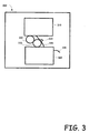
- Fig. 3 is a block diagram of a waterless lithographic printing system incorporating an embodiment of the multi-layer printing plate.
- the illustrated printing system 300 includes an image processing system 310 and a media finishing section 320.
- the details of various printing systems can vary greatly and so, the particular are not provided as they are well known to those skilled in the relevant art.
- a multi-layered printing plate 330 is incorporated into the system for receiving ink from the image processing system 310 and depositing the ink onto roller 332, which in turn, in cooperation with pressure roller 334, transfers the image to media 336.
- the media 336 is then fed through the media finishing section 320.
- the various embodiments of the printing plate can be embodied in a variety of printing systems.
- Fig. 4 is a flow diagram illustrating an exemplary process for utilizing various embodiments of the layered printing member.
- the printing member is created such that it includes an oleophilic solid substrate; a laser absorbing imaging layer and an oleophobic silicone layer.
- the laser absorbing imaging layer is positioned above the substrate and comprises an infrared absorbing substance of approximately 15-70% by weight of a self-condensation oligomeric amine.
- the oleophobic silicone layer is positioned above the laser absorbing imaging layer.
- the printing member is installed in IR imaging system to burn the image 412.
- the printing member is installed onto a waterless lithographic printing machine 420.
- the waterless lithographic printing machine is operated to generate impressions 430.
- the solid substrate is created such that it absorbs approximately 90% of the infrared radiation that is incident on the surface of the solid substrate.
- the action of creating the printing member further comprises creating a printing member in which the laser absorbing imaging layer comprises an oligomeric amine concentration that is approximately between 30 to 70% by weight.
- the action of creating a printer member further comprises creating a printer member in which the laser absorbing imaging layer further comprises a dispersion of inorganic nano-particles in a concentration of 5-60% by weight.
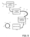
- Fig. 5 is a process flow diagram showing the steps involved in creating various embodiments of the printing member.
- a substrate 11 is fed into the laser absorbing imaging layer applicator 510.
- the laser absorbing imaging layer 12 is thus positioned above the substrate 11.
- the laser absorbing imaging layer 12 may be directly on top of the substrate 11 or may be separated by one or more additional layers, such as an insulating layer, an IR trapping layer, an IR filtering layer etc.
- the material is then fed through the oleophobic layer applicator 520 which operates to place an oleophobic layer 13, such as silicone, positioned above the laser absorbing imagine layer 12.
- the printing member is ready for imaging and as such, is fed to the plate imager and clean out processor 530 where the plate is exposed to an image via IR radiation and then the ablated areas are removed by the clean out procedure leaving an image on the printing member in which the substrate 11 is exposed for receiving ink, and non-ablated oleophobic areas 13 remain for repelling ink - thus creating an image.
- the plate is then fed through a drum installer 540 where the imaged plate is placed on a drum and ready to be installed in a printing system.
- a process block may include a processor, memory, control signals to operate mechanical devices, sensors for detecting operations by mechanical devices, etc.
- compositions for the laser absorbing layer of an exemplary printing plate Following are few examples of suitable compositions for the laser absorbing layer of an exemplary printing plate and techniques of constructing and utilizing the plates.
- a laser absorbing imaging layer (which would correspond to element 12 in Figs. 1 and 2 ) of the following composition was applied to a substrate (which would correspond to element 11 in Figs. 1 and 2 ) comprised of clear 175 micron polyester film SH-92 of SKC Co.
- the coating composition was applied to the substrate using a No 5 mayer rod and dried for 2 minutes at 140°C.
- the weight of the dry coating was 0.4 g/ m 2 .
- the following silicone layer composition was applied: Ingredients of silicone layer Weight % Vinyl terminated polydemethyl siloxane VM& P Naphtha solution, sold under the trade name SS4331 by GE BAYER SILICONES. GMBH & CO. KG, Bergen op Zoom, Netherlands 50 Platinum catalyst sold by the trade name SS8010 by GE BAYER SILICONES. GMBH & CO.
- the silicone coating was applied using a No 8 mayer rod and dried for a period of 2 minutes at 140°C.
- the weight of the dry coating was 2 g/ m2.
- the plate was imaged by KodakTM Quantum Trendsetter 800 thermal CTP system, laser wave length 830 nm. Silicone debris was cleaned by wiping with soapy water.
- the plate was installed on a GTO-46 printing press, and during a printing run, good quality impressions were obtained.
- a laser absorbing imaging layer of the following composition was applied to a clear 175 micron polyester film SH-92 of SKC Co. Ltd, Seocho-gu Seoul, South Korea: Ingredients of laser absorbing layer Weight % Methylethyl ketone dispersion of colloidal silica, sold under the trade name of MEK-ST by Nissan Chemical America Corporation, Houston, TX, USA 1.6 Infra red Dye, sold under trade name IR-9807 by Adam Gates & Company LLC , Flemington, NJ, USA 1.6 Methylated Imino Melamine crosslinking agent, sold under the trade name of CymelTM 327 by Cytec Industries Inc, West Paterson, NJ, USA 3.1 Phosphoric acid 85% 0.1 Methyl ethyl Ketone 46.8 Isopropyl Alcohol 46.8
- the coating composition was applied to the substrate using a No 5 mayer rod and dried for 2 minutes at 140°C.
- the weight of dry coating was 0.5 g/ m2.
- the plate was imaged by a KodakTM Quantum Trendsetter 800 thermal CTP system, laser wave length 830 nm. Silicone debris was cleaned by wiping with soapy water.
- the plate was installed on GTO-46 printing press, and during a printing run, good quality impressions were obtained.
- composition for a thermal insulating layer was applied to a 150 micron aluminum sheet 1050 H18 of Alcoa European Mill Products, Geneve Switzerland: Ingredients of isolation formula Weight % UCARTM VMCH Vinyl Resin, Texas, USA 10 Methylethyl Ketone 70 Isopropyl Alcohol 20
- the thermal insulating layer was applied to the substrate using a No 8 mayer rod and dried for a period of 2 minutes at 120°C.
- the weight of dry coating was 3 g/ m2.
- Example 2 On top of the insulating layer, the laser absorbing imaging layer and the silicone layer as described in Example 2 was applied.
- the plate was then imaged by KodakTM Quantum Trendsetter 800 thermal CTP system, laser wave length 830 nm.
- the silicone debris was cleaned by wiping with soapy water.
- the plate was installed on GTO-46 printing press, and during a printing run, good quality impressions were obtained.
- the laser absorbing imaging layer and the silicone layer as described in example 2 were applied to a black 188 micron polyester film SB00 of SKC Co. Ltd, Seocho-gu Seoul, South Korea.
- the plate in this example 4 was then imaged by a KodakTM Quantum Trendsetter 800 thermal CTP system, laser wave length 830 nm.
- the silicone debris was cleaned by wiping with soapy water.
- the plate was installed on GTO-46 printing press and after a printing run, good quality 350 lpi resolution impressions were obtained.
- a 0.15 micron thick aluminum/aluminumoxide MMO layer was applied by vacuum vapor deposition to a black 188 ⁇ polyester SB00 of SKC film.
- the aluminum/aluminumoxide MMO layer was applied by Hanita Coatings Ltd., Hanita, Israel using the same processemployed when it manufactures the B05012P, B03612P products.
- the silicone layer as described in example 1 was then applied onto the aluminum/aluminum oxide layer.
- the plate of example 5 was then imaged using a KodakTM Quantum Trendsetter 800 thermal CTP system, laser wave length 830 nm.
- the silicone debris was cleaned by wiping with soapy water.
- the plate was then installed onto a GTO-46 printing press and after a printing run, good quality resolution impressions were obtained.
- each of the verbs, "comprise”, “include” and “have”, and conjugates thereof, are used to indicate that the object or objects of the verb are not necessarily a complete listing of members, components, elements, or parts of the subject or subjects of the verb.
Landscapes
- Physics & Mathematics (AREA)
- Optics & Photonics (AREA)
- Thermal Sciences (AREA)
- Engineering & Computer Science (AREA)
- Manufacturing & Machinery (AREA)
- Printing Plates And Materials Therefor (AREA)
- Manufacture Or Reproduction Of Printing Formes (AREA)
Description
- The present disclosure is related to the field of lithographic printing, and more particularly, to the manufacturing of a lithographic printing member that is used in waterless offset printing systems.
- In offset lithography printing, an image is presented on a lithographic printing member, such as a printing plate or a printing cylinder, wherein the imaged area has a pattern of ink-accepting (oleophilic and/or hydrophobic) and ink-repellent (oleophobic and/or hydrophilic) surface areas. There are two general offset printing methods, a wet method and a dry method (waterless). The wet method, which is the traditional method, uses a fluid that is dampened (or "fountain") to the printing member prior to the ink. The fluid, such as water, covers the ink-repellent surface areas and repels the ink that is applied later to the printing plate, but does not affect the oleophilic character of the image areas. Therefore, traditionally, the non-image areas are called hydrophilic areas while the ink-accepting areas are called hydrophobic areas.
- The typical dry or waterless lithographic printing member has at least two layers with at least two layers having a different affinity for printing ink. For instance, one layer is made of or includes an oleophobic material that rejects ink, such as silicone rubber. Another layer is made of or includes an oleophilic material such as polyester. Therefore, in dry printing systems, the plate is simply inked and the ink is carried by the oleophilic areas that were exposed imagewise.
- It should be noted that the terms "printing member", "printing plate", "lithographic printing member" and "plate" are used interchangeably herein. It also should be noted that the terms "ink-accepting" and "oleophilic" are used interchangeably herein and it should be noted that the terms "ink-repellent" and "oleophobic" are used interchangeably herein.
- In waterless printing methods, the image is patterned over the plate creating ink-accepting (oleophilic) and ink-rejecting (oleophobic) surface areas. Ink that is applied to the lithographic printing member is carried by the oleophilic areas and is transferred to a recording medium in the image-wise pattern. Typically, the inked printing member first makes contact with an intermediate surface called a blanket cylinder, which, in turn, applies the image ink to the paper or other recording medium.
- There are several ways to expose the image over a printing member. Some of those methods involve direct computer to plate (CTP) equipment. Common imaging methods of a printing member exposes the printing member image-wise by a computer control laser radiation, usually using infrared (IR) or near IR radiation. The image-wise IR radiation elevates the temperature of the IR absorber and deanchoring the top oleophobic layer.
- For example, Great Britain patent
1489308 U.S. Pat. No. 5,339,737 (Lewis et al. ),U.S. Pat. No. 5,353,705 (Lewis et al. ),U.S. Pat. No. 5,378,580 (Leenders ). - Many of the currently available ablatable printing plates designed to absorb laser energy include an IR absorbing substance, such as a pigment and/or dye, and self-oxidizing polymer binders such as nitrocellulose and a crosslinking agent like melamine.
- All ablative plates, after imaging, undergoing a cleaning process to remove residue of the ablated silicone from the plate. The cleaning process can include the application of solvents and can be a wet or dry process. Solvent cleaning processes are not user friendly or ecologically friendly. Water based or dry cleaning of the plate is a more suitable ecological means of cleaning the plate, but it requires effort and time to release all residue of silicone from the image, especially in the case of high resolution imaging such as 300 lpi or more.
- A few examples of existing printing members and methods for manufacturing them are now presented as further background of the related technology. One example of prior art IR ablative waterless printing plates utilize a silicone top layer, a second layer or imaging layer including IR sensitive laser absorbing material and a substrate. The top layer is silicone, like polydimethylsiloxane rubber, with a thickness of about 2 microns. The second layer is made of a polymer and/or a cross-linkable resin, IR absorbing pigment or dye, and a cross-linking agent. In many existing plates, the polymer or resin layer can be made up of nitrocellulose, which operates as the ablating agent layer as it is self-oxidized by thermal irradiation. Other polymers are also described for such applications, such as derivatives of vinyl terpolymer, polyvinylidenchloride, cyanoacrylate polymer binder etc. Usually, the thickness of such layers is in the range of 0.5-1 microns. In other prior art printing member, the second layer can be constructed of metal, metal oxide or a combination thereof, usually applied in vacuum.
- Typically, the substrates described in the prior art is made from aluminum or polyester film and is either clear or white. In case of aluminum substrates, an insulating layer is applied between the substrate and the imaging IR sensitive layer. This insulating layer serves to prevent the imaging layer from dissipating the thermal energy provided by the laser to the metal or substrate. This insulating layer typically has oleophilic ink receptive properties.
- In the high-end offset printing field, there is need for printing high-quality images with resolution higher than 300 lpi. In high resolution printing, the sharpness of the dot edges is very important to achieve high-quality images, and the clean out of the printing member after exposure is equally important. However, achieving sharp dot edges and high-degrees of cleanout in existing waterless lithographic plates that are thermally ablated can be significantly difficult. The creation of sharp dot edges and the complete removal of silicone residues from small dense dot areas is a difficult task in preparing common waterless thermal ablative printing members.
- Embodiments of lithographic printing members disclosed throughout the present disclosure solve the above-described needs in the art. One or more of the disclosed embodiments provide a lithographic printing member, having a layer structure, with improved imaging and ablating debris cleaning abilities. It will be appreciated that the disclosed embodiments, and features and/or aspects thereof present novel printing members that allow for obtaining high quality images with fine and precision dots in printing resolution of 350 lpi or more.
- In some embodiments, an exemplary IR ablation layer, which comprises IR absorbing dye and amine resin as the basic organic matter of the ablation layer, can provide fine and accurate imaging and easy cleaning of debris after the imaging. In some embodiments, the amine resin can be in the amount of approximately 15% or more of the composition of the imaging layer, by weight. A preferable range of the amount, by weight, of the amine resin can be approximately 30-70% of the composition of the imaging layer. The utilization of amine resin as the basic organic matter is not a common practice in the printing plate art. The reason for this is that in common printing plates the amine resin, similar to melamine based oligomers, are used as a crosslinker and not as the basic organic material. In an exemplary novel printing plate, the amine resin replaces the traditional polymer that is used as a basic organic matter of the imaging layer.
- In addition, adding colloidal silica to the composition of the imaging layer improves the cleanout properties, thereby allowing the printing of clean and accurate images at resolution 350 lpi or higher.
- Furthermore, using a substrate that absorbs IR radiation, such as a black substrate in contrast to existing printing plates having reflective substrates, an unexpected high quality of exposed dot is obtained. Black or non-reflective substrate operates to prevent dot extension or image distortion near the edges of the imaging area and delivers sharp dots.
- Advantageously, the novel and unobvious approach of the present disclosure delivers a sharper image and enables an increased printing resolution.
-
-
Fig.1 is cross-sectional view of an exemplary three-layer structure of printing plate utilizing black PET or other non-metal substrate that absorbs IR radiation. -
Fig.2 is cross-sectional view of an exemplary four-layer structure of plate with aluminum substrate or other metal substrate. -
Fig. 3 is a block diagram of a waterless lithographic printing system incorporating an embodiment of the multi-layer printing plate. -
Fig. 4 is a flowchart with relevant actions of a waterless lithographic printing method incorporating an embodiment of the multi-layer printing plate. -
Fig. 5 is a process flow diagram showing the steps involved in creating various embodiments of the printing member. - The present disclosure presents various embodiments, as well as features and aspects that can be incorporated into one or more embodiments, of techniques for fabricating and structures of a layered printing plate that attains a high degree of clarity and improved clean out. The various embodiments of the layered printing plate utilize an amine resin rather than a traditional polymer as the basic organic matter of the imaging layer, the addition of colloidal silica into the imaging layer to improve the cleanout properties, and utilizing a substrate that absorbs IR radiation rather than reflects it.
- Turning now to the figures in which like numerals represent like elements throughout the several views, exemplary embodiments of the layered printing plate are described. The purpose of the drawings is to describe exemplary embodiments and not for production. Therefore, dimensions of components and features shown in the figures are chosen for convenience and clarity of presentation and are not necessarily shown to scale.
-
Fig.1 is cross-sectional view of an exemplary three-layer structure of a printing plate utilizing black PET or other non-metal substrate that absorbs IR radiation. The illustrated embodiment is shown as including anoleophilic substrate layer 11, a laser absorbingimaging layer 12, and anolcophobic layer 13. The laser absorbingimaging layer 12 can be made of a composition including an infrared absorptive substance, such as a pigment and/or dye and is positioned above thesubstrate layer 11. It should be appreciated that the term "positioned above" can indicated that the layer is formed on the surface of the underlying layer or, the layer may have one or more additional layers between it and the underlying layer to which it is above. Theoleophobic layer 13 is positionedabovethe imaging layer 12. -
Fig.2 is cross-sectional view of an exemplary four-layer structure of plate with aluminum substrate or other metal substrate. The embodiment illustrated inFig. 2 illustrates an alternative embodiment that may have a primer orinsulation layer 14 in between theimaging layer 12 and theoleophobic layer 13. The primer layer may be added for improving adhesion of theimaging layer 12 to thesubstrate 11. The insulatinglayer 14 is beneficial when thesubstrate 11 is aluminum or other metal. - Among other things, layer 14 functions to prevent the metal from dissipating the thermal energy provided by the laser.
Layer 14 has oleophilic, or ink receptive properties. Many types of polymeric coatings or inorganic coatings can be used for preparing this layer. Illustrative examples of ink receptive resins forlayer 14 comprise phenol-, cresol- and melamine-formaldehyde resins, vinyl resins, polyester resins, acrylate resins, polyvinyl chloride, polyvinyl acetate, polystyrene, etc. - The
substrate 11 serves two major functions. First of all, thesubstrate 11 may provide the mechanical support for the printing member. Furthermore, thesubstrate 11 may have a different affinity characteristics for ink than thetop layer 13. - An exemplary printing member may have a
substrate 11 made of polymer, such as but not limited to polyester. Thesubstrate 11 has an oleophilic surface. The surface of theoleophilic substrate 11 is exposed by imaging radiation that imagewise ablateslayer substrate 11 may be in the range of 0.003 to 0.02 inches (about 0.08 mm to 0.5 mm). A wide variety of materials may be used for fabricating thesubstrate 11 such as, but not limited to, polymers, paper, metal etc. In particular, the substrate may be made of polyvinylchlorides (PVC) polyesters, polycarbonates, polyolefins, etc. Such substrates may be made of polyethylene terephthalate film, such as but not limited to the polyester films available under the trademarks of MYLAR™ and MELINEX™ polyester films from DuPont Teijin™ Films, polyester films of SKC. At the end of the fabrication of the printing member, thesubstrate 11 may be laminated over a metal substrate, such as but not limited to aluminum. The lamination may be done for improving the mechanical features of the printing member. - Black polyester, when is used as the material for
substrate 11, improves plate performance by providing sharper images with well defined elements and dots and allows printing at high imaging resolutions - 3501pi and higher. Such polyester contains carbon black which is an IR absorptive pigment. Further, black polyster may have insignificant reflectivity from the substrate surface. The measured reflected portion of incident IR radiation from the exemplary blacked substrate is typically below approximately 10%. In most of the substrate, the refelected energy was about 7%-8% of the incident energy. Because such polyester film at the above-mentioned thickness has practically zero transparency, it absorbs more than approximately 92% of the IR radiation that ispassed through the imaging layer. The black and non-reflective substrate prevents any reflection back to the imaging layer of IR radiation. Advantageously, using a black substrate reduces the dots gain or image distortion near the edges. Reducing the dot extension improves the sharpness of the image and enables printing in a higher resolution. This is accomplished because the printed dots with reduced dot extension can fit the size of a dot in high resolution. Suitable types of black polyester films for thesubstrate 11 are SB00 of SKC, Seocho-gu Seoul, South Korea, Lumirror X30 of Toray Plastics, North Kingstown, LTI GB of Lee Tat Industrial, Kowloon, Hong Kong. - Other exemplary embodiment may use other substrates with low reflectivity. As an alternative embodiment, an additional non-ablative coating layer with low reflectivity can be applied on the
substrate 11. -
Exemplary imaging layer 12 can comprise IR absorptive pigments like carbon black and/or IR absorptive dyes like phthalocyanine, merocyanine, polymethine, indoaniline, oxonol, pyrilium, squarilium, dithiolene dyes or thin metal, metal oxide or metal/metal oxide layer, like titanium, titanium oxide, aluminum/aluminum oxide. - Another exemplary embodiment of the plate member includes a laser absorbing
imaging layer 12 that further includes a dispersion of inorganic nano-particles. A few non-limiting examples of such inorganic nano-particles include colloidal silica and colloidal alumina. The placement of the colloidal or nano-particles in imaging layer improves post-imaging cleaning and allows for the complete removal of silicone residues even from very dense screen with resolutions of 350 lpi and higher. In various embodiments, the concentration of colloidal or nano-particles in the imaging layer may be in the range, of 5 to 60% in solid by weight. - In some exemplary embodiments of the printing members, the imaging layer or the IR absorbing layer, may comprise self-condensation oligomeric amine resin as the basic organic matter of the imaging layer. In some embodiments, the amine resin can be in the amount, by weight, of 15% or more of the composition of the imaging layer. A preferable range of the amount of the amine resin can be from approximately 30-70% of the composition of the imaging layer. Employing amine resin as the basic organic matter is unusual in the printing plate art because in common printing plates, amine resin like melamine based oligomers are used as crosslinker and not as the basic organic material. In the exemplary embodiments, the amine resin replaces the traditional polymer that is used as a basic organic matter of the imaging layer. Using the amine resin as the basic organic matter improves the sharpness of the image and allows for a higher resolution in the image. A non-limiting example of an oligomeric amines includes methylated melamines, known under trade mark Cymel™ from Cytex. Amine resins like methylated and alkylated melamines usually are used as crosslinking additives for hydroxyl and carboxyl containing polymers.
- The amine resin is used as the main binder and film-forming material of the imaging layer and provides non-predicted improvements in imaging results. Different types of amine resins may be used such as, methylated melamines, alkilated melamines, imino mixed ether melamines, buthylated melamines, urea oligomers and other.
-
Fig. 3 is a block diagram of a waterless lithographic printing system incorporating an embodiment of the multi-layer printing plate. The illustratedprinting system 300 includes animage processing system 310 and amedia finishing section 320. The details of various printing systems can vary greatly and so, the particular are not provided as they are well known to those skilled in the relevant art. However, as can be seen from the illustrated environment, amulti-layered printing plate 330 is incorporated into the system for receiving ink from theimage processing system 310 and depositing the ink ontoroller 332, which in turn, in cooperation withpressure roller 334, transfers the image tomedia 336. Themedia 336 is then fed through themedia finishing section 320. Thus, it can be appreciated that the various embodiments of the printing plate can be embodied in a variety of printing systems. -
Fig. 4 is a flow diagram illustrating an exemplary process for utilizing various embodiments of the layered printing member. Initially the process of creating prints using a waterlesslithographic printing machine 400 begins by creating theprinting member 410 as described in more detail in conjunction withFigs. 1 and 2 . The printing member is created such that it includes an oleophilic solid substrate; a laser absorbing imaging layer and an oleophobic silicone layer. The laser absorbing imaging layer is positioned above the substrate and comprises an infrared absorbing substance of approximately 15-70% by weight of a self-condensation oligomeric amine. The oleophobic silicone layer is positioned above the laser absorbing imaging layer. Next the printing member is installed in IR imaging system to burn theimage 412. Next procedure is cleaning ofdebris 415. Next, the printing member is installed onto a waterlesslithographic printing machine 420. Finally, the waterless lithographic printing machine is operated to generateimpressions 430. In some embodiments, the solid substrate is created such that it absorbs approximately 90% of the infrared radiation that is incident on the surface of the solid substrate. In other embodiments, the action of creating the printing member further comprises creating a printing member in which the laser absorbing imaging layer comprises an oligomeric amine concentration that is approximately between 30 to 70% by weight. In yet other embodiments, the action of creating a printer member further comprises creating a printer member in which the laser absorbing imaging layer further comprises a dispersion of inorganic nano-particles in a concentration of 5-60% by weight. -
Fig. 5 is a process flow diagram showing the steps involved in creating various embodiments of the printing member. Initially, asubstrate 11 is fed into the laser absorbingimaging layer applicator 510. As a result, the laser absorbingimaging layer 12 is thus positioned above thesubstrate 11. As previously mentioned, the laser absorbingimaging layer 12 may be directly on top of thesubstrate 11 or may be separated by one or more additional layers, such as an insulating layer, an IR trapping layer, an IR filtering layer etc. The material is then fed through theoleophobic layer applicator 520 which operates to place anoleophobic layer 13, such as silicone, positioned above the laser absorbing imaginelayer 12. At this point the printing member is ready for imaging and as such, is fed to the plate imager and clean outprocessor 530 where the plate is exposed to an image via IR radiation and then the ablated areas are removed by the clean out procedure leaving an image on the printing member in which thesubstrate 11 is exposed for receiving ink, and non-ablatedoleophobic areas 13 remain for repelling ink - thus creating an image. Finally, in a particular embodiment, the plate is then fed through adrum installer 540 where the imaged plate is placed on a drum and ready to be installed in a printing system. - It should be understood that the various stages or processes illustrated in
Fig. 5 can be performed by a machine, a micro-controller, an electro-mechanical system, a computer system, manual controls, or any variety or combination of these and other techniques. As such, a process block may include a processor, memory, control signals to operate mechanical devices, sensors for detecting operations by mechanical devices, etc. - Following are few examples of suitable compositions for the laser absorbing layer of an exemplary printing plate and techniques of constructing and utilizing the plates.
- In example 1, a laser absorbing imaging layer (which would correspond to
element 12 inFigs. 1 and 2 ) of the following composition was applied to a substrate (which would correspond toelement 11 inFigs. 1 and 2 ) comprised of clear 175 micron polyester film SH-92 of SKC Co. Ltd, Seocho-gu Seoul, South Korea:Ingredients of laser absorbing layer Weight, % Infra red dye, sold under trade name IR-9807 by Adam Gates & Company LLC , Flemington, NJ, USA 1.6 Methylated Imino Melamine crosslinking agent, sold under the trade name of Cymel™ 327 by Cytec Industries Inc, West Paterson, NJ, USA 3.2 Phosphoric acid 85% 0.1 Methyl ethyl Ketone 47.6 Isopropyl Alcohol 47.6 - The coating composition was applied to the substrate using a No 5 mayer rod and dried for 2 minutes at 140°C. The weight of the dry coating was 0.4 g/ m2. Further for example 1, on top of the laser absorbing imaging layer, the following silicone layer composition was applied:
Ingredients of silicone layer Weight % Vinyl terminated polydemethyl siloxane VM& P Naphtha solution, sold under the trade name SS4331 by GE BAYER SILICONES. GMBH & CO. KG, Bergen op Zoom, Netherlands 50 Platinum catalyst sold by the trade name SS8010 by GE BAYER SILICONES. GMBH & CO. KG, Bergen op Zoom, Netherlands 0.7 Reactive polysiloxane copolymer crosslinker agent sold under the trade name SL6020 by GE BAYER SILICONES. GMBH & CO. KG, Bergen op Zoom, Netherlands. 0.7 Heptane 48.6 - The silicone coating was applied using a No 8 mayer rod and dried for a period of 2 minutes at 140°C. The weight of the dry coating was 2 g/ m2.
- The plate was imaged by Kodak™ Quantum Trendsetter 800 thermal CTP system, laser wave length 830 nm. Silicone debris was cleaned by wiping with soapy water.
- The plate was installed on a GTO-46 printing press, and during a printing run, good quality impressions were obtained.
- In example 2, a laser absorbing imaging layer of the following composition was applied to a clear 175 micron polyester film SH-92 of SKC Co. Ltd, Seocho-gu Seoul, South Korea:
Ingredients of laser absorbing layer Weight % Methylethyl ketone dispersion of colloidal silica, sold under the trade name of MEK-ST by Nissan Chemical America Corporation, Houston, TX, USA 1.6 Infra red Dye, sold under trade name IR-9807 by Adam Gates & Company LLC , Flemington, NJ, USA 1.6 Methylated Imino Melamine crosslinking agent, sold under the trade name of Cymel™ 327 by Cytec Industries Inc, West Paterson, NJ, USA 3.1 Phosphoric acid 85% 0.1 Methyl ethyl Ketone 46.8 Isopropyl Alcohol 46.8 - The coating composition was applied to the substrate using a No 5 mayer rod and dried for 2 minutes at 140°C. The weight of dry coating was 0.5 g/ m2.
- Further, for example 2, on top of this laser absorbing layer the above-described silicone layer composition for example 1 was applied.
- The plate was imaged by a Kodak™ Quantum Trendsetter 800 thermal CTP system, laser wave length 830 nm. Silicone debris was cleaned by wiping with soapy water.
- The plate was installed on GTO-46 printing press, and during a printing run, good quality impressions were obtained.
- In example 3, the following composition for a thermal insulating layer was applied to a 150 micron aluminum sheet 1050 H18 of Alcoa European Mill Products, Geneve Switzerland:
Ingredients of isolation formula Weight % UCAR™ VMCH Vinyl Resin, Texas, USA 10 Methylethyl Ketone 70 Isopropyl Alcohol 20 - The thermal insulating layer was applied to the substrate using a No 8 mayer rod and dried for a period of 2 minutes at 120°C. The weight of dry coating was 3 g/ m2.
- On top of the insulating layer, the laser absorbing imaging layer and the silicone layer as described in Example 2 was applied.
- The plate was then imaged by Kodak™ Quantum Trendsetter 800 thermal CTP system, laser wave length 830 nm. The silicone debris was cleaned by wiping with soapy water.
- The plate was installed on GTO-46 printing press, and during a printing run, good quality impressions were obtained.
- In example 4, the laser absorbing imaging layer and the silicone layer as described in example 2 were applied to a black 188 micron polyester film SB00 of SKC Co. Ltd, Seocho-gu Seoul, South Korea.
- Reflectivity of the polyester film SB00 at wave length 830, as measured on a Cary UV-VIS-IR Photospectrometer, Model 500 was between 7 and 7.5 %. Taking this measurement into account along with the characteristic that this substrate has zero transmission, then it is clear that the substrate absorbs 93-93.5% of incident radiation.
- The plate in this example 4 was then imaged by a Kodak™ Quantum Trendsetter 800 thermal CTP system, laser wave length 830 nm. The silicone debris was cleaned by wiping with soapy water.
- The plate was installed on GTO-46 printing press and after a printing run, good quality 350 lpi resolution impressions were obtained.
- In example 5, a 0.15 micron thick aluminum/aluminumoxide MMO layer was applied by vacuum vapor deposition to a black 188µ polyester SB00 of SKC film. The aluminum/aluminumoxide MMO layer was applied by Hanita Coatings Ltd., Hanita, Israel using the same processemployed when it manufactures the B05012P, B03612P products. The silicone layer as described in example 1 was then applied onto the aluminum/aluminum oxide layer.
- The plate of example 5 was then imaged using a Kodak™ Quantum Trendsetter 800 thermal CTP system, laser wave length 830 nm. The silicone debris was cleaned by wiping with soapy water.
- The plate was then installed onto a GTO-46 printing press and after a printing run, good quality resolution impressions were obtained.
- In the description and claims of the present application, each of the verbs, "comprise", "include" and "have", and conjugates thereof, are used to indicate that the object or objects of the verb are not necessarily a complete listing of members, components, elements, or parts of the subject or subjects of the verb.
Claims (14)
- A waterless lithographic printing member, comprising:a. an oleophilic solid substrate (11);b. a laser absorbing imaging layer (12) positioned above the substrate (11), wherein the laser absorbing imaging layer (12) comprises an infrared absorbing substance;c. a silicone layer (13) positioned above the laser absorbing imaging layer (12), the silicone layer (13) having oleophobic characteristics;d. wherein the laser absorbing imaging layer (12) is comprised of 30 to 70% by weight of a self-condensation oligomeric amine and wherein the self-condensation oligomeric amine is the main film forming material of the laser absorbing imaging layer (12).
- The printing member of claim 1, wherein the oligomeric amine is a crosslinking agent on the base of melamine.
- The printing member of claim 1, wherein the laser absorbing imaging layer (12) comprises a dispersion of inorganic nano-particles.
- The printing member of claim 3, wherein the nano-particles comprise colloidal silica.
- The printing member of claim 3, wherein the nano-particles comprise colloidal alumina.
- The printing member of claim 3, wherein the dispersion of inorganic nano-particles is in a concentration of 5-60% by weight.
- The printing member of claim 1, further comprises an oleophilic insulation layer (14) positioned between the substrate (11) and the imaging layer (12).
- The printing member of claim 1, wherein the oleophilic solid substrate (11) absorbs 90% or more of the infrared radiation that is incident onto the oleophilic solid substrate (11).
- The printing member of claim 1, wherein the oleophilic solid substrate (11) comprises an infrared absorbing substance.
- The printing member of claim 9, wherein the infrared absorbing substance is carbon black.
- The printing member of claim 1, wherein the oleophilic solid substrate (11) is a black polyester film.
- A method of creating prints using a waterless lithographic printing machine (400), the method comprises the actions of:creating a printer member (410) that comprises an oleophilic solid substrate (11); a laser absorbing imaging layer (12) positioned above the substrate (11), wherein the laser absorbing imaging layer (12) comprises 30-70% by weight of a self-condensation oligomeric amine and an infrared absorbing substance, the self-condensation oligomeric amine being the main film forming material of the laser absorbing imaging layer (12), and an oleophobic silicone layer (13) positioned above the laser absorbing imaging layer (12);installing the printing member (410) into an IR laser imaging device to expose an image onto the printing member (410);installing the imaged printing member onto a waterless lithographic printing machine (420); andobtaining impressions from the waterless lithographic printing machine (420).
- The method of claim 12, wherein the action of creating a printer member (410) further comprises creating a printer member (410) in which the oleophilic solid substrate (11) absorbs 90% of the infrared radiation that is incident on the surface of the solid substrate (11).
- The method of claim 12, wherein the action of creating a printer member (410) further comprises creating a printer member (410) in which the laser absorbing imaging layer (12) further comprises a dispersion of inorganic nano-particles in a concentration of 5-60% by weight.
Applications Claiming Priority (1)
| Application Number | Priority Date | Filing Date | Title |
|---|---|---|---|
| US38061610P | 2010-09-07 | 2010-09-07 |
Publications (3)
| Publication Number | Publication Date |
|---|---|
| EP2425985A2 EP2425985A2 (en) | 2012-03-07 |
| EP2425985A3 EP2425985A3 (en) | 2012-08-08 |
| EP2425985B1 true EP2425985B1 (en) | 2014-03-05 |
Family
ID=44651249
Family Applications (1)
| Application Number | Title | Priority Date | Filing Date |
|---|---|---|---|
| EP11180254.2A Not-in-force EP2425985B1 (en) | 2010-09-07 | 2011-09-06 | Thermal imagable waterless lithographic member |
Country Status (2)
| Country | Link |
|---|---|
| US (1) | US9440476B2 (en) |
| EP (1) | EP2425985B1 (en) |
Families Citing this family (8)
| Publication number | Priority date | Publication date | Assignee | Title |
|---|---|---|---|---|
| US8967043B2 (en) * | 2011-05-17 | 2015-03-03 | Presstek, Inc. | Ablation-type lithographic printing members having improved exposure sensitivity and related methods |
| US9387659B2 (en) | 2011-05-17 | 2016-07-12 | Presstek, Llc | Ablation-type lithographic printing members having improved exposure sensitivity and related methods |
| US10124571B2 (en) | 2011-05-17 | 2018-11-13 | Presstek, Llc. | Ablation-type lithographic printing members having improved exposure sensitivity and related methods |
| US9387660B2 (en) | 2011-05-17 | 2016-07-12 | Presstek, Llc | Ablation-type lithographic printing members having improved shelf life and related methods |
| EP2890563B1 (en) * | 2012-08-22 | 2018-03-21 | Presstek, LLC. | Ablation-type lithographic printing members having improved shelf life and related methods |
| US20170136799A1 (en) | 2015-11-18 | 2017-05-18 | Kevin Ray | Dry lithographic imaging and printing with printing members having aluminum substrates |
| EP3504061B1 (en) * | 2016-08-25 | 2020-04-29 | Presstek, LLC. | Dry printing with simplified plate cleaning |
| JP7040887B2 (en) * | 2016-10-04 | 2022-03-23 | 東洋製罐株式会社 | Waterless planographic printing for seamless cans and its manufacturing method |
Family Cites Families (8)
| Publication number | Priority date | Publication date | Assignee | Title |
|---|---|---|---|---|
| GB1489308A (en) | 1974-03-18 | 1977-10-19 | Scott Paper Co | Laser imagable dry planographic printing plate blank |
| US5378580A (en) | 1992-06-05 | 1995-01-03 | Agfa-Gevaert, N.V. | Heat mode recording material and method for producing driographic printing plates |
| US5339737B1 (en) | 1992-07-20 | 1997-06-10 | Presstek Inc | Lithographic printing plates for use with laser-discharge imaging apparatus |
| US5353705A (en) | 1992-07-20 | 1994-10-11 | Presstek, Inc. | Lithographic printing members having secondary ablation layers for use with laser-discharge imaging apparatus |
| JPH09234375A (en) * | 1996-03-01 | 1997-09-09 | Mitsubishi Paper Mills Ltd | Photoreactive harmful material removal material |
| US6071369A (en) * | 1996-10-29 | 2000-06-06 | Agfa-Gevaert, N.V. | Method for making an lithographic printing plate with improved ink-uptake |
| US7234806B2 (en) * | 2002-06-20 | 2007-06-26 | Xerox Corporation | Phase change ink imaging component with fluorosilicone layer |
| US7966934B2 (en) * | 2005-11-04 | 2011-06-28 | Gary Ganghui Teng | Process for on-press developing overcoat-free lithographic printing plate |
-
2011
- 2011-09-04 US US13/225,473 patent/US9440476B2/en not_active Expired - Fee Related
- 2011-09-06 EP EP11180254.2A patent/EP2425985B1/en not_active Not-in-force
Also Published As
| Publication number | Publication date |
|---|---|
| EP2425985A2 (en) | 2012-03-07 |
| US20120055363A1 (en) | 2012-03-08 |
| EP2425985A3 (en) | 2012-08-08 |
| US9440476B2 (en) | 2016-09-13 |
Similar Documents
| Publication | Publication Date | Title |
|---|---|---|
| EP2425985B1 (en) | Thermal imagable waterless lithographic member | |
| AU725426B2 (en) | Method of lithographic imaging with reduced debris-generated performance degradation and related constructions | |
| JP3569032B2 (en) | Lithographic printing plate image forming method | |
| AU750729B2 (en) | Infrared laser-imageable lithographic printing members and methods of preparing and imaging such printing members | |
| AU744513B2 (en) | Laser-imageable printing members for wet lithographic printing | |
| US9605150B2 (en) | Recording media and related methods | |
| EP0969967B1 (en) | Direct write waterless imaging member with improved ablation properties and methods of imaging and printing | |
| EP0795420B1 (en) | Lithographic printing plate adapted to be imaged by ablation | |
| US6197478B1 (en) | Method for making a driographic printing plate involving the use of a heat-sensitive imaging element | |
| CA2345856C (en) | Lithographic imaging with metal-based, non-ablative wet printing members | |
| JP4033949B2 (en) | Method for making a driographic printing plate comprising the use of a thermosensitive imaging element | |
| CA2564874A1 (en) | Lithographic printing members having primer layers and method of imaging said members | |
| AU730600B2 (en) | Method of lithographic imaging with reduced debris-generated performance degradation and related constructions | |
| US6124073A (en) | Heat-sensitive imaging element and a method for producing lithographic plates therewith | |
| US9827759B2 (en) | Dry printing with simplified plate cleaning | |
| EP2230076B1 (en) | Lithographic imaging with printing members having metal imaging bilayers | |
| EP0922572A1 (en) | A heat sensitive imaging element and a method for producing lithographic plates therewith | |
| EP3504061B1 (en) | Dry printing with simplified plate cleaning | |
| JPH11240273A (en) | Heat-sensitive image-forming element, and manufacture of lithographic printing plate using the same |
Legal Events
| Date | Code | Title | Description |
|---|---|---|---|
| AK | Designated contracting states |
Kind code of ref document: A2 Designated state(s): AL AT BE BG CH CY CZ DE DK EE ES FI FR GB GR HR HU IE IS IT LI LT LU LV MC MK MT NL NO PL PT RO RS SE SI SK SM TR |
|
| AX | Request for extension of the european patent |
Extension state: BA ME |
|
| PUAI | Public reference made under article 153(3) epc to a published international application that has entered the european phase |
Free format text: ORIGINAL CODE: 0009012 |
|
| RIC1 | Information provided on ipc code assigned before grant |
Ipc: B41C 1/10 20060101ALI20120306BHEP Ipc: B41N 1/00 20060101AFI20120306BHEP |
|
| PUAL | Search report despatched |
Free format text: ORIGINAL CODE: 0009013 |
|
| AK | Designated contracting states |
Kind code of ref document: A3 Designated state(s): AL AT BE BG CH CY CZ DE DK EE ES FI FR GB GR HR HU IE IS IT LI LT LU LV MC MK MT NL NO PL PT RO RS SE SI SK SM TR |
|
| AX | Request for extension of the european patent |
Extension state: BA ME |
|
| RIC1 | Information provided on ipc code assigned before grant |
Ipc: B41C 1/10 20060101ALI20120629BHEP Ipc: B41N 1/00 20060101AFI20120629BHEP |
|
| 17P | Request for examination filed |
Effective date: 20130208 |
|
| GRAP | Despatch of communication of intention to grant a patent |
Free format text: ORIGINAL CODE: EPIDOSNIGR1 |
|
| INTG | Intention to grant announced |
Effective date: 20130410 |
|
| GRAS | Grant fee paid |
Free format text: ORIGINAL CODE: EPIDOSNIGR3 |
|
| GRAP | Despatch of communication of intention to grant a patent |
Free format text: ORIGINAL CODE: EPIDOSNIGR1 |
|
| INTG | Intention to grant announced |
Effective date: 20130916 |
|
| GRAA | (expected) grant |
Free format text: ORIGINAL CODE: 0009210 |
|
| AK | Designated contracting states |
Kind code of ref document: B1 Designated state(s): AL AT BE BG CH CY CZ DE DK EE ES FI FR GB GR HR HU IE IS IT LI LT LU LV MC MK MT NL NO PL PT RO RS SE SI SK SM TR |
|
| REG | Reference to a national code |
Ref country code: GB Ref legal event code: FG4D |
|
| REG | Reference to a national code |
Ref country code: CH Ref legal event code: EP |
|
| REG | Reference to a national code |
Ref country code: AT Ref legal event code: REF Ref document number: 654577 Country of ref document: AT Kind code of ref document: T Effective date: 20140315 |
|
| REG | Reference to a national code |
Ref country code: IE Ref legal event code: FG4D |
|
| REG | Reference to a national code |
Ref country code: DE Ref legal event code: R096 Ref document number: 602011005197 Country of ref document: DE Effective date: 20140417 |
|
| REG | Reference to a national code |
Ref country code: AT Ref legal event code: MK05 Ref document number: 654577 Country of ref document: AT Kind code of ref document: T Effective date: 20140305 |
|
| REG | Reference to a national code |
Ref country code: NL Ref legal event code: VDEP Effective date: 20140305 |
|
| PG25 | Lapsed in a contracting state [announced via postgrant information from national office to epo] |
Ref country code: LT Free format text: LAPSE BECAUSE OF FAILURE TO SUBMIT A TRANSLATION OF THE DESCRIPTION OR TO PAY THE FEE WITHIN THE PRESCRIBED TIME-LIMIT Effective date: 20140305 Ref country code: NO Free format text: LAPSE BECAUSE OF FAILURE TO SUBMIT A TRANSLATION OF THE DESCRIPTION OR TO PAY THE FEE WITHIN THE PRESCRIBED TIME-LIMIT Effective date: 20140605 |
|
| REG | Reference to a national code |
Ref country code: LT Ref legal event code: MG4D |
|
| PG25 | Lapsed in a contracting state [announced via postgrant information from national office to epo] |
Ref country code: SE Free format text: LAPSE BECAUSE OF FAILURE TO SUBMIT A TRANSLATION OF THE DESCRIPTION OR TO PAY THE FEE WITHIN THE PRESCRIBED TIME-LIMIT Effective date: 20140305 Ref country code: FI Free format text: LAPSE BECAUSE OF FAILURE TO SUBMIT A TRANSLATION OF THE DESCRIPTION OR TO PAY THE FEE WITHIN THE PRESCRIBED TIME-LIMIT Effective date: 20140305 Ref country code: CY Free format text: LAPSE BECAUSE OF FAILURE TO SUBMIT A TRANSLATION OF THE DESCRIPTION OR TO PAY THE FEE WITHIN THE PRESCRIBED TIME-LIMIT Effective date: 20140305 Ref country code: AT Free format text: LAPSE BECAUSE OF FAILURE TO SUBMIT A TRANSLATION OF THE DESCRIPTION OR TO PAY THE FEE WITHIN THE PRESCRIBED TIME-LIMIT Effective date: 20140305 |
|
| PG25 | Lapsed in a contracting state [announced via postgrant information from national office to epo] |
Ref country code: HR Free format text: LAPSE BECAUSE OF FAILURE TO SUBMIT A TRANSLATION OF THE DESCRIPTION OR TO PAY THE FEE WITHIN THE PRESCRIBED TIME-LIMIT Effective date: 20140305 Ref country code: RS Free format text: LAPSE BECAUSE OF FAILURE TO SUBMIT A TRANSLATION OF THE DESCRIPTION OR TO PAY THE FEE WITHIN THE PRESCRIBED TIME-LIMIT Effective date: 20140305 Ref country code: LV Free format text: LAPSE BECAUSE OF FAILURE TO SUBMIT A TRANSLATION OF THE DESCRIPTION OR TO PAY THE FEE WITHIN THE PRESCRIBED TIME-LIMIT Effective date: 20140305 |
|
| PG25 | Lapsed in a contracting state [announced via postgrant information from national office to epo] |
Ref country code: BG Free format text: LAPSE BECAUSE OF FAILURE TO SUBMIT A TRANSLATION OF THE DESCRIPTION OR TO PAY THE FEE WITHIN THE PRESCRIBED TIME-LIMIT Effective date: 20140605 Ref country code: NL Free format text: LAPSE BECAUSE OF FAILURE TO SUBMIT A TRANSLATION OF THE DESCRIPTION OR TO PAY THE FEE WITHIN THE PRESCRIBED TIME-LIMIT Effective date: 20140305 Ref country code: CZ Free format text: LAPSE BECAUSE OF FAILURE TO SUBMIT A TRANSLATION OF THE DESCRIPTION OR TO PAY THE FEE WITHIN THE PRESCRIBED TIME-LIMIT Effective date: 20140305 Ref country code: EE Free format text: LAPSE BECAUSE OF FAILURE TO SUBMIT A TRANSLATION OF THE DESCRIPTION OR TO PAY THE FEE WITHIN THE PRESCRIBED TIME-LIMIT Effective date: 20140305 Ref country code: IS Free format text: LAPSE BECAUSE OF FAILURE TO SUBMIT A TRANSLATION OF THE DESCRIPTION OR TO PAY THE FEE WITHIN THE PRESCRIBED TIME-LIMIT Effective date: 20140705 Ref country code: BE Free format text: LAPSE BECAUSE OF FAILURE TO SUBMIT A TRANSLATION OF THE DESCRIPTION OR TO PAY THE FEE WITHIN THE PRESCRIBED TIME-LIMIT Effective date: 20140305 Ref country code: RO Free format text: LAPSE BECAUSE OF FAILURE TO SUBMIT A TRANSLATION OF THE DESCRIPTION OR TO PAY THE FEE WITHIN THE PRESCRIBED TIME-LIMIT Effective date: 20140305 |
|
| PG25 | Lapsed in a contracting state [announced via postgrant information from national office to epo] |
Ref country code: SK Free format text: LAPSE BECAUSE OF FAILURE TO SUBMIT A TRANSLATION OF THE DESCRIPTION OR TO PAY THE FEE WITHIN THE PRESCRIBED TIME-LIMIT Effective date: 20140305 Ref country code: ES Free format text: LAPSE BECAUSE OF FAILURE TO SUBMIT A TRANSLATION OF THE DESCRIPTION OR TO PAY THE FEE WITHIN THE PRESCRIBED TIME-LIMIT Effective date: 20140305 Ref country code: PL Free format text: LAPSE BECAUSE OF FAILURE TO SUBMIT A TRANSLATION OF THE DESCRIPTION OR TO PAY THE FEE WITHIN THE PRESCRIBED TIME-LIMIT Effective date: 20140305 |
|
| REG | Reference to a national code |
Ref country code: DE Ref legal event code: R097 Ref document number: 602011005197 Country of ref document: DE |
|
| PG25 | Lapsed in a contracting state [announced via postgrant information from national office to epo] |
Ref country code: PT Free format text: LAPSE BECAUSE OF FAILURE TO SUBMIT A TRANSLATION OF THE DESCRIPTION OR TO PAY THE FEE WITHIN THE PRESCRIBED TIME-LIMIT Effective date: 20140707 |
|
| PLBE | No opposition filed within time limit |
Free format text: ORIGINAL CODE: 0009261 |
|
| STAA | Information on the status of an ep patent application or granted ep patent |
Free format text: STATUS: NO OPPOSITION FILED WITHIN TIME LIMIT |
|
| PG25 | Lapsed in a contracting state [announced via postgrant information from national office to epo] |
Ref country code: DK Free format text: LAPSE BECAUSE OF FAILURE TO SUBMIT A TRANSLATION OF THE DESCRIPTION OR TO PAY THE FEE WITHIN THE PRESCRIBED TIME-LIMIT Effective date: 20140305 |
|
| 26N | No opposition filed |
Effective date: 20141208 |
|
| REG | Reference to a national code |
Ref country code: DE Ref legal event code: R097 Ref document number: 602011005197 Country of ref document: DE Effective date: 20141208 |
|
| PG25 | Lapsed in a contracting state [announced via postgrant information from national office to epo] |
Ref country code: IT Free format text: LAPSE BECAUSE OF FAILURE TO SUBMIT A TRANSLATION OF THE DESCRIPTION OR TO PAY THE FEE WITHIN THE PRESCRIBED TIME-LIMIT Effective date: 20140305 |
|
| PG25 | Lapsed in a contracting state [announced via postgrant information from national office to epo] |
Ref country code: LU Free format text: LAPSE BECAUSE OF FAILURE TO SUBMIT A TRANSLATION OF THE DESCRIPTION OR TO PAY THE FEE WITHIN THE PRESCRIBED TIME-LIMIT Effective date: 20140906 Ref country code: MC Free format text: LAPSE BECAUSE OF FAILURE TO SUBMIT A TRANSLATION OF THE DESCRIPTION OR TO PAY THE FEE WITHIN THE PRESCRIBED TIME-LIMIT Effective date: 20140305 |
|
| REG | Reference to a national code |
Ref country code: CH Ref legal event code: PL |
|
| PG25 | Lapsed in a contracting state [announced via postgrant information from national office to epo] |
Ref country code: SI Free format text: LAPSE BECAUSE OF FAILURE TO SUBMIT A TRANSLATION OF THE DESCRIPTION OR TO PAY THE FEE WITHIN THE PRESCRIBED TIME-LIMIT Effective date: 20140305 |
|
| REG | Reference to a national code |
Ref country code: IE Ref legal event code: MM4A |
|
| REG | Reference to a national code |
Ref country code: FR Ref legal event code: ST Effective date: 20150529 |
|
| PG25 | Lapsed in a contracting state [announced via postgrant information from national office to epo] |
Ref country code: LI Free format text: LAPSE BECAUSE OF NON-PAYMENT OF DUE FEES Effective date: 20140930 Ref country code: CH Free format text: LAPSE BECAUSE OF NON-PAYMENT OF DUE FEES Effective date: 20140930 |
|
| PG25 | Lapsed in a contracting state [announced via postgrant information from national office to epo] |
Ref country code: FR Free format text: LAPSE BECAUSE OF NON-PAYMENT OF DUE FEES Effective date: 20140930 Ref country code: IE Free format text: LAPSE BECAUSE OF NON-PAYMENT OF DUE FEES Effective date: 20140906 |
|
| PG25 | Lapsed in a contracting state [announced via postgrant information from national office to epo] |
Ref country code: SM Free format text: LAPSE BECAUSE OF FAILURE TO SUBMIT A TRANSLATION OF THE DESCRIPTION OR TO PAY THE FEE WITHIN THE PRESCRIBED TIME-LIMIT Effective date: 20140305 |
|
| PG25 | Lapsed in a contracting state [announced via postgrant information from national office to epo] |
Ref country code: GR Free format text: LAPSE BECAUSE OF FAILURE TO SUBMIT A TRANSLATION OF THE DESCRIPTION OR TO PAY THE FEE WITHIN THE PRESCRIBED TIME-LIMIT Effective date: 20140606 Ref country code: MT Free format text: LAPSE BECAUSE OF FAILURE TO SUBMIT A TRANSLATION OF THE DESCRIPTION OR TO PAY THE FEE WITHIN THE PRESCRIBED TIME-LIMIT Effective date: 20140305 |
|
| PG25 | Lapsed in a contracting state [announced via postgrant information from national office to epo] |
Ref country code: HU Free format text: LAPSE BECAUSE OF FAILURE TO SUBMIT A TRANSLATION OF THE DESCRIPTION OR TO PAY THE FEE WITHIN THE PRESCRIBED TIME-LIMIT; INVALID AB INITIO Effective date: 20110906 Ref country code: TR Free format text: LAPSE BECAUSE OF FAILURE TO SUBMIT A TRANSLATION OF THE DESCRIPTION OR TO PAY THE FEE WITHIN THE PRESCRIBED TIME-LIMIT Effective date: 20140305 |
|
| PG25 | Lapsed in a contracting state [announced via postgrant information from national office to epo] |
Ref country code: MK Free format text: LAPSE BECAUSE OF FAILURE TO SUBMIT A TRANSLATION OF THE DESCRIPTION OR TO PAY THE FEE WITHIN THE PRESCRIBED TIME-LIMIT Effective date: 20140305 |
|
| PG25 | Lapsed in a contracting state [announced via postgrant information from national office to epo] |
Ref country code: AL Free format text: LAPSE BECAUSE OF FAILURE TO SUBMIT A TRANSLATION OF THE DESCRIPTION OR TO PAY THE FEE WITHIN THE PRESCRIBED TIME-LIMIT Effective date: 20140305 |
|
| P01 | Opt-out of the competence of the unified patent court (upc) registered |
Effective date: 20230526 |
|
| PGFP | Annual fee paid to national office [announced via postgrant information from national office to epo] |
Ref country code: GB Payment date: 20230927 Year of fee payment: 13 |
|
| PGFP | Annual fee paid to national office [announced via postgrant information from national office to epo] |
Ref country code: DE Payment date: 20230927 Year of fee payment: 13 |
|
| REG | Reference to a national code |
Ref country code: DE Ref legal event code: R082 Ref document number: 602011005197 Country of ref document: DE Representative=s name: MEISSNER BOLTE PATENTANWAELTE RECHTSANWAELTE P, DE |
|
| REG | Reference to a national code |
Ref country code: DE Ref legal event code: R119 Ref document number: 602011005197 Country of ref document: DE |
|
| GBPC | Gb: european patent ceased through non-payment of renewal fee |
Effective date: 20240906 |
|
| PG25 | Lapsed in a contracting state [announced via postgrant information from national office to epo] |
Ref country code: DE Free format text: LAPSE BECAUSE OF NON-PAYMENT OF DUE FEES Effective date: 20250401 |
|
| PG25 | Lapsed in a contracting state [announced via postgrant information from national office to epo] |
Ref country code: GB Free format text: LAPSE BECAUSE OF NON-PAYMENT OF DUE FEES Effective date: 20240906 |