EP2425941A1 - Cutting apparatus and cutting method - Google Patents
Cutting apparatus and cutting method Download PDFInfo
- Publication number
- EP2425941A1 EP2425941A1 EP20110179506 EP11179506A EP2425941A1 EP 2425941 A1 EP2425941 A1 EP 2425941A1 EP 20110179506 EP20110179506 EP 20110179506 EP 11179506 A EP11179506 A EP 11179506A EP 2425941 A1 EP2425941 A1 EP 2425941A1
- Authority
- EP
- European Patent Office
- Prior art keywords
- disc blade
- substrate
- unit
- cutting
- linear edge
- Prior art date
- Legal status (The legal status is an assumption and is not a legal conclusion. Google has not performed a legal analysis and makes no representation as to the accuracy of the status listed.)
- Withdrawn
Links
- 238000005520 cutting process Methods 0.000 title claims abstract description 158
- 238000000034 method Methods 0.000 title claims description 9
- 239000000758 substrate Substances 0.000 claims abstract description 99
- 238000013459 approach Methods 0.000 claims description 5
- 230000001419 dependent effect Effects 0.000 claims 1
- 230000007246 mechanism Effects 0.000 description 22
- 238000009966 trimming Methods 0.000 description 19
- 238000012545 processing Methods 0.000 description 8
- 238000012546 transfer Methods 0.000 description 7
- 230000008878 coupling Effects 0.000 description 5
- 238000010168 coupling process Methods 0.000 description 5
- 238000005859 coupling reaction Methods 0.000 description 5
- 239000004065 semiconductor Substances 0.000 description 3
- 238000009751 slip forming Methods 0.000 description 3
- 238000010586 diagram Methods 0.000 description 2
- 239000011521 glass Substances 0.000 description 2
- 230000002452 interceptive effect Effects 0.000 description 2
- 230000002093 peripheral effect Effects 0.000 description 2
- 230000009467 reduction Effects 0.000 description 2
- 230000001154 acute effect Effects 0.000 description 1
- 230000008901 benefit Effects 0.000 description 1
- 230000006835 compression Effects 0.000 description 1
- 238000007906 compression Methods 0.000 description 1
- 238000001514 detection method Methods 0.000 description 1
- 238000012986 modification Methods 0.000 description 1
- 230000004048 modification Effects 0.000 description 1
- 230000001681 protective effect Effects 0.000 description 1
- 230000035939 shock Effects 0.000 description 1
Images







Classifications
-
- B—PERFORMING OPERATIONS; TRANSPORTING
- B26—HAND CUTTING TOOLS; CUTTING; SEVERING
- B26D—CUTTING; DETAILS COMMON TO MACHINES FOR PERFORATING, PUNCHING, CUTTING-OUT, STAMPING-OUT OR SEVERING
- B26D1/00—Cutting through work characterised by the nature or movement of the cutting member or particular materials not otherwise provided for; Apparatus or machines therefor; Cutting members therefor
- B26D1/01—Cutting through work characterised by the nature or movement of the cutting member or particular materials not otherwise provided for; Apparatus or machines therefor; Cutting members therefor involving a cutting member which does not travel with the work
- B26D1/12—Cutting through work characterised by the nature or movement of the cutting member or particular materials not otherwise provided for; Apparatus or machines therefor; Cutting members therefor involving a cutting member which does not travel with the work having a cutting member moving about an axis
- B26D1/14—Cutting through work characterised by the nature or movement of the cutting member or particular materials not otherwise provided for; Apparatus or machines therefor; Cutting members therefor involving a cutting member which does not travel with the work having a cutting member moving about an axis with a circular cutting member, e.g. disc cutter
- B26D1/20—Cutting through work characterised by the nature or movement of the cutting member or particular materials not otherwise provided for; Apparatus or machines therefor; Cutting members therefor involving a cutting member which does not travel with the work having a cutting member moving about an axis with a circular cutting member, e.g. disc cutter coacting with a fixed member
- B26D1/205—Cutting through work characterised by the nature or movement of the cutting member or particular materials not otherwise provided for; Apparatus or machines therefor; Cutting members therefor involving a cutting member which does not travel with the work having a cutting member moving about an axis with a circular cutting member, e.g. disc cutter coacting with a fixed member for thin material, e.g. for sheets, strips or the like
-
- B—PERFORMING OPERATIONS; TRANSPORTING
- B26—HAND CUTTING TOOLS; CUTTING; SEVERING
- B26D—CUTTING; DETAILS COMMON TO MACHINES FOR PERFORATING, PUNCHING, CUTTING-OUT, STAMPING-OUT OR SEVERING
- B26D7/00—Details of apparatus for cutting, cutting-out, stamping-out, punching, perforating, or severing by means other than cutting
- B26D7/18—Means for removing cut-out material or waste
- B26D7/1845—Means for removing cut-out material or waste by non mechanical means
- B26D7/1854—Means for removing cut-out material or waste by non mechanical means by air under pressure
-
- B—PERFORMING OPERATIONS; TRANSPORTING
- B26—HAND CUTTING TOOLS; CUTTING; SEVERING
- B26D—CUTTING; DETAILS COMMON TO MACHINES FOR PERFORATING, PUNCHING, CUTTING-OUT, STAMPING-OUT OR SEVERING
- B26D7/00—Details of apparatus for cutting, cutting-out, stamping-out, punching, perforating, or severing by means other than cutting
- B26D7/26—Means for mounting or adjusting the cutting member; Means for adjusting the stroke of the cutting member
- B26D7/2614—Means for mounting the cutting member
- B26D7/2621—Means for mounting the cutting member for circular cutters
-
- B—PERFORMING OPERATIONS; TRANSPORTING
- B26—HAND CUTTING TOOLS; CUTTING; SEVERING
- B26D—CUTTING; DETAILS COMMON TO MACHINES FOR PERFORATING, PUNCHING, CUTTING-OUT, STAMPING-OUT OR SEVERING
- B26D7/00—Details of apparatus for cutting, cutting-out, stamping-out, punching, perforating, or severing by means other than cutting
- B26D7/26—Means for mounting or adjusting the cutting member; Means for adjusting the stroke of the cutting member
- B26D7/2628—Means for adjusting the position of the cutting member
- B26D7/2635—Means for adjusting the position of the cutting member for circular cutters
-
- B—PERFORMING OPERATIONS; TRANSPORTING
- B26—HAND CUTTING TOOLS; CUTTING; SEVERING
- B26F—PERFORATING; PUNCHING; CUTTING-OUT; STAMPING-OUT; SEVERING BY MEANS OTHER THAN CUTTING
- B26F1/00—Perforating; Punching; Cutting-out; Stamping-out; Apparatus therefor
- B26F1/38—Cutting-out; Stamping-out
- B26F1/3806—Cutting-out; Stamping-out wherein relative movements of tool head and work during cutting have a component tangential to the work surface
- B26F1/3813—Cutting-out; Stamping-out wherein relative movements of tool head and work during cutting have a component tangential to the work surface wherein the tool head is moved in a plane parallel to the work in a coordinate system fixed with respect to the work
- B26F1/3826—Cutting-out; Stamping-out wherein relative movements of tool head and work during cutting have a component tangential to the work surface wherein the tool head is moved in a plane parallel to the work in a coordinate system fixed with respect to the work using a rotary circular cutting member
-
- B—PERFORMING OPERATIONS; TRANSPORTING
- B26—HAND CUTTING TOOLS; CUTTING; SEVERING
- B26D—CUTTING; DETAILS COMMON TO MACHINES FOR PERFORATING, PUNCHING, CUTTING-OUT, STAMPING-OUT OR SEVERING
- B26D1/00—Cutting through work characterised by the nature or movement of the cutting member or particular materials not otherwise provided for; Apparatus or machines therefor; Cutting members therefor
- B26D1/01—Cutting through work characterised by the nature or movement of the cutting member or particular materials not otherwise provided for; Apparatus or machines therefor; Cutting members therefor involving a cutting member which does not travel with the work
- B26D1/12—Cutting through work characterised by the nature or movement of the cutting member or particular materials not otherwise provided for; Apparatus or machines therefor; Cutting members therefor involving a cutting member which does not travel with the work having a cutting member moving about an axis
- B26D1/14—Cutting through work characterised by the nature or movement of the cutting member or particular materials not otherwise provided for; Apparatus or machines therefor; Cutting members therefor involving a cutting member which does not travel with the work having a cutting member moving about an axis with a circular cutting member, e.g. disc cutter
- B26D1/157—Cutting through work characterised by the nature or movement of the cutting member or particular materials not otherwise provided for; Apparatus or machines therefor; Cutting members therefor involving a cutting member which does not travel with the work having a cutting member moving about an axis with a circular cutting member, e.g. disc cutter rotating about a movable axis
- B26D1/1575—Cutting through work characterised by the nature or movement of the cutting member or particular materials not otherwise provided for; Apparatus or machines therefor; Cutting members therefor involving a cutting member which does not travel with the work having a cutting member moving about an axis with a circular cutting member, e.g. disc cutter rotating about a movable axis for thin material, e.g. for sheets, strips or the like
-
- B—PERFORMING OPERATIONS; TRANSPORTING
- B26—HAND CUTTING TOOLS; CUTTING; SEVERING
- B26D—CUTTING; DETAILS COMMON TO MACHINES FOR PERFORATING, PUNCHING, CUTTING-OUT, STAMPING-OUT OR SEVERING
- B26D1/00—Cutting through work characterised by the nature or movement of the cutting member or particular materials not otherwise provided for; Apparatus or machines therefor; Cutting members therefor
- B26D1/01—Cutting through work characterised by the nature or movement of the cutting member or particular materials not otherwise provided for; Apparatus or machines therefor; Cutting members therefor involving a cutting member which does not travel with the work
- B26D1/12—Cutting through work characterised by the nature or movement of the cutting member or particular materials not otherwise provided for; Apparatus or machines therefor; Cutting members therefor involving a cutting member which does not travel with the work having a cutting member moving about an axis
- B26D1/14—Cutting through work characterised by the nature or movement of the cutting member or particular materials not otherwise provided for; Apparatus or machines therefor; Cutting members therefor involving a cutting member which does not travel with the work having a cutting member moving about an axis with a circular cutting member, e.g. disc cutter
- B26D1/157—Cutting through work characterised by the nature or movement of the cutting member or particular materials not otherwise provided for; Apparatus or machines therefor; Cutting members therefor involving a cutting member which does not travel with the work having a cutting member moving about an axis with a circular cutting member, e.g. disc cutter rotating about a movable axis
- B26D1/18—Cutting through work characterised by the nature or movement of the cutting member or particular materials not otherwise provided for; Apparatus or machines therefor; Cutting members therefor involving a cutting member which does not travel with the work having a cutting member moving about an axis with a circular cutting member, e.g. disc cutter rotating about a movable axis mounted on a movable carriage
- B26D1/185—Cutting through work characterised by the nature or movement of the cutting member or particular materials not otherwise provided for; Apparatus or machines therefor; Cutting members therefor involving a cutting member which does not travel with the work having a cutting member moving about an axis with a circular cutting member, e.g. disc cutter rotating about a movable axis mounted on a movable carriage for thin material, e.g. for sheets, strips or the like
-
- Y—GENERAL TAGGING OF NEW TECHNOLOGICAL DEVELOPMENTS; GENERAL TAGGING OF CROSS-SECTIONAL TECHNOLOGIES SPANNING OVER SEVERAL SECTIONS OF THE IPC; TECHNICAL SUBJECTS COVERED BY FORMER USPC CROSS-REFERENCE ART COLLECTIONS [XRACs] AND DIGESTS
- Y10—TECHNICAL SUBJECTS COVERED BY FORMER USPC
- Y10T—TECHNICAL SUBJECTS COVERED BY FORMER US CLASSIFICATION
- Y10T83/00—Cutting
- Y10T83/04—Processes
- Y10T83/05—With reorientation of tool between cuts
-
- Y—GENERAL TAGGING OF NEW TECHNOLOGICAL DEVELOPMENTS; GENERAL TAGGING OF CROSS-SECTIONAL TECHNOLOGIES SPANNING OVER SEVERAL SECTIONS OF THE IPC; TECHNICAL SUBJECTS COVERED BY FORMER USPC CROSS-REFERENCE ART COLLECTIONS [XRACs] AND DIGESTS
- Y10—TECHNICAL SUBJECTS COVERED BY FORMER USPC
- Y10T—TECHNICAL SUBJECTS COVERED BY FORMER US CLASSIFICATION
- Y10T83/00—Cutting
- Y10T83/768—Rotatable disc tool pair or tool and carrier
- Y10T83/7755—Carrier for rotatable tool movable during cutting
-
- Y—GENERAL TAGGING OF NEW TECHNOLOGICAL DEVELOPMENTS; GENERAL TAGGING OF CROSS-SECTIONAL TECHNOLOGIES SPANNING OVER SEVERAL SECTIONS OF THE IPC; TECHNICAL SUBJECTS COVERED BY FORMER USPC CROSS-REFERENCE ART COLLECTIONS [XRACs] AND DIGESTS
- Y10—TECHNICAL SUBJECTS COVERED BY FORMER USPC
- Y10T—TECHNICAL SUBJECTS COVERED BY FORMER US CLASSIFICATION
- Y10T83/00—Cutting
- Y10T83/768—Rotatable disc tool pair or tool and carrier
- Y10T83/7872—Tool element mounted for adjustment
Definitions
- the present invention relates to a technique of cutting a cover sheet which covers a substrate.
- Japanese Patent Laid-Open No. 08-229883 discloses an apparatus which cuts roll paper by moving a disc blade along a fixed blade.
- Japanese Patent Laid-Open No. 2004-025402 discloses an apparatus which trims a protective tape for a semiconductor wafer along the periphery of a semiconductor wafer.
- Japanese Patent Laid-Open No. 2007-054926 also discloses an apparatus which cuts a sheet-like member by moving a disc blade along a guide member.
- a cover sheet covers a substrate such as a glass substrate or a semiconductor wafer to protect its surface.
- a solar cell module substrate uses a cover sheet to protect the light-receiving surface and binds a plurality of members formed in a multilayer form which constitute the substrate.
- a portion of the cover sheet which protrudes from the periphery of the substrate is not necessary, and hence it is necessary to cut it.
- a cover sheet along the linear edges without causing damage such as crack to the linear edges.
- the present invention in its first aspect provides a cutting apparatus as specified in claims 1 to 9.
- the present invention in its second aspect provides a cutting method as specified in claims 10 to 12.
- Fig. 1 is a plan view of a cutting apparatus according to an embodiment of the present invention
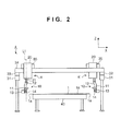
- Fig. 2 is a front view of the cutting apparatus
- Fig. 3 is a perspective view of a head unit
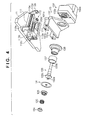
- Fig. 4 is an exploded perspective view of the main components of a cutting unit
- Fig. 5 is a sectional view of a driving unit
- Fig. 6A is an enlarged view of the blade tip portion of a disc blade
- Fig. 6B is a view for explaining how the blade tip portion cuts a cover sheet
- Fig. 7A is an enlarged view of the blade tip portion of another example of the disc blade, and Fig. 7B is a view for explaining how the blade tip portion cuts a cover sheet;
- Fig. 8 is a block diagram of a controller
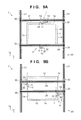
- Figs. 9A and 9B are views for explaining teaching
- Figs. 10A and 10B are views for explaining trimming operation
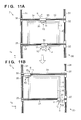
- Figs. 11A and 11B are views for explaining trimming operation
- Figs. 12A and 12B are views for explaining trimming operation
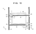
- Fig. 13 is a view for explaining trimming operation
- Figs. 14A and 14B are views for explaining another example of trimming operation
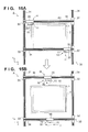
- Figs. 15A and 15B are views for explaining another example of trimming operation.
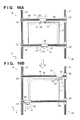
- Figs. 16A and 16B are views for explaining another example of trimming operation.
- Fig. 1 is a plan view of a cutting apparatus A according to an embodiment of the present invention.
- Fig. 2 is a front view of the cutting apparatus A.
- arrows X and Y indicate two directions perpendicular to each other in a horizontal plane, and an arrow Z indicates a vertical direction.
- the cutting apparatus A includes head units H, a moving device 30 which moves the head units H on an X-Y plane, and a holding unit 40 which holds a substrate 1.
- the head units H include cutting units 10 and pivoting/lifting units 20 which move vertically and cause the cutting units 10 to pivot. These components will be described below.
- the holding unit 40 has an upper surface serving as a horizontal surface on which the substrate 1 is placed.
- the upper surface of the holding unit 40 may be provided with a fixing mechanism to releasably fix the substrate 1.
- This fixing mechanism includes, for example, a chucking mechanism which chucks the substrate 1.
- the fixing mechanism allows to a cover sheet (not shown in Figs. 1 and 2 ) covering the substrate 1 to be accurately cut.
- the substrate 1 is, for example, a glass plate.
- the substrate 1 is assumed to be a rectangular substrate with four sides each of which forms a linear edge 1a.
- the cutting apparatus A of the embodiment trims the cover sheet along the linear edges 1a.
- the cutting apparatus A can be applied to not only a substrate whose contour is constituted by only the linear edges 1a like the substrate 1 but also substrates having various shapes each including a linear edge as part of the contour.
- a convey mechanism (not shown) conveys and places the substrate 1 onto the holding unit 40.
- the substrate 1 is positioned so as to make the respective sides parallel to the X and Y directions, and is placed on the upper surface of the holding unit 40 in a horizontal posture.
- the moving device 30 roughly includes head unit moving units (rail portions 34 and driving sliders 35) which move the head units H, moving units (rail portions 31, driving sliders 32, and driven sliders 33) which move the head unit moving units. These components will be described in detail below.
- the moving device 30 includes the pair of rail portions 31 which are spaced apart from each other in the X direction and extend in the Y direction.
- the rail portions 31 have guide grooves 31a formed in their upper surfaces so as to extend in the Y direction.
- One of the rail portions 31 is provided with the two driving sliders 32 which can move on the rail portions 31 while being guided by the guide grooves 31a.
- the other rail portion 31 is provided with the two driven sliders 33 which can move on the rail portions 31 while being guided by the guide grooves 31a.
- the driving sliders 32 and the driven sliders 33 are paired. In this embodiment, two pairs of the driving sliders 32 and the driven sliders 33 are provided.
- Each driving slider 32 includes an independent driving source and independently travels by itself on the rail portion 31.
- a mechanism for making the driving slider 32 travel by itself for example, a ball screw mechanism can be used, which includes a ball screw provided on the rail portion 31 and a ball nut which threadably engages with the ball screw.
- Each driving slider 32 can include a ball nut and a rotation driving unit (for example, a hollow motor) which rotatably holds the ball nut and rotates it.
- Each driven slider 33 has no mechanism for making it travel by itself.
- the rail portion 34 is laid across the driving slider 32 and driven slider 33 of each pair.
- the rail portion 34 extends in the X direction and translates in the Y direction as the driving slider 32 moves in the Y direction.
- the rail portion 34 has a guide groove 34a formed in its upper surface so as to extend in the X direction.
- Each rail portion 34 is provided with the driving slider 35 which can move on the rail portion 34 while being guided by the guide groove 34a.
- the driving slider 35 travels by itself on the rail portion 34 by using the same mechanism as that of the driving slider 32 described above.
- the pivoting/lifting unit 20 is fixed to each driving slider 35. Moving the driving slider 35 can move the pivoting/lifting unit 20 and the cutting unit 10 in the X direction.
- this embodiment can move the head units H on an X-Y plane.
- the embodiment is configured to move the cutting units 10 with respect to the substrate 1.
- the moving device 30 includes sensor units (not shown) for detecting the positions of the cutting units 10 in the X-Y direction.
- sensors include, for example, sensor units for detecting the positions of the driving sliders 32 and 35. More specifically, if the driving sources for the driving sliders 32 and 35 are motors, such sensors include sensors (for example, encoders) which detect the amounts of rotation of the motors.
- Fig. 3 is a perspective view of the cutting unit 10 and pivoting/lifting unit 20.
- the pivoting/lifting unit 20 includes a shaft body 21 and a mechanism (not shown) which allows the shaft body 21 to rotate around its axis (a broken line L1 in Fig. 2 ) and moves the shaft body 21 up and down.
- the shaft body 21 has its axis in the Z direction.
- the cutting unit 10 is coupled to the shaft body 21 so that rotating the shaft body 21 can make the cutting unit 10 pivot about the pivot center axis (the broken line L1 in Fig. 2 ) in the Z direction and maintain its pivot angle, and moving the shaft body 21 up and down can move the cutting unit 10 up and down in the Z direction.
- rotating the shaft body 21 can make the cutting unit 10 pivot about the pivot center axis (the broken line L1 in Fig. 2 ) in the Z direction and maintain its pivot angle, and moving the shaft body 21 up and down can move the cutting unit 10 up and down in the Z direction.
- Making the cutting unit 10 pivot and maintaining its pivot angle can adjust the angle (intersection angle) between a plane (a vertical plane in the Z direction in this embodiment) perpendicular to the substrate surface of the substrate 1 including the linear edges 1a to be subjected to trimming and a plane (a vertical plane in the Z direction in the embodiment) formed by the disc blade 14. Adjusting and maintaining this angle can make the disc blade 14 abut against the edges of the substrate 1 at a preferred angle, thereby preventing the edges of the substrate 1 from being damaged at the time of cutting the cover sheet.
- moving the cutting unit 10 up and down can adjust the cutting blade position (height position) of a blade tip 14b formed on the peripheral surface of the disc blade 14 (to be described later) with respect to a plane (a vertical plane in the Z direction in this embodiment) perpendicular to the substrate surface of the substrate 1 which includes the linear edge 1a subjected to trimming and a plane (a vertical plane in the Z direction in the embodiment) formed on the disc blade 14.
- a known mechanism can be used as a mechanism which rotates and moves the shaft body 21 up and down.
- a mechanism for rotating the shaft body 21 includes a combination of a driving source such as a motor and a mechanism such as a gear mechanism or a belt mechanism.
- a mechanism for maintaining the rotational angle of the shaft body 21 if, for example, a servo motor is used as a driving source, the electromagnetic lock function of the servo motor can be used.
- a mechanism for moving the shaft body 21 up and down can include a combination of a driving source such as a motor and a mechanism such as a rack-pinion mechanism.
- each pivoting/lifting unit 20 includes a sensor unit (not shown) for detecting the pivot angle (pivot position) and Z-direction position of the cutting unit 10.
- a sensor unit for detecting the pivot angle (pivot position) and Z-direction position of the cutting unit 10.
- the driving source which rotates and moves the shaft body 21 up and down is a motor
- such a sensor include a sensor (for example, an encoder) which detects the amount of rotation of the motor.
- Fig. 4 is an exploded perspective view of the main components of the cutting unit 10.
- Fig. 5 is a sectional view of a driving unit 13.
- the cutting unit 10 includes a plate-like main support portion 11, a coupling portion 12 which couples the shaft body 21 of the pivoting/lifting unit 20 to the main support portion 11, and the driving unit 13 which supports the disc blade 14 vertically with respect to a plane direction of the substrate 1 (a horizontal direction in this embodiment) and rotates the disc blade 14.
- the driving unit 13 includes a support portion (slider) 131 having an almost L-shaped cross-section which has a vertical portion and a horizontal portion.
- a driving unit 132 is attached to the rear surface side (opposite to the side on which the disc blade 14 is located) of the vertical portion of the support portion 131.
- the driving unit 132 includes a motor 132a as a driving source and a reduction gear 132b which decelerates the output of the motor 132a.
- a rear end portion 133b of a rotating shaft body 133 of the disc blade 14 is connected to the reduction gear 132b. As the motor 132a rotates, the rotating shaft body 133 rotates about its axis.
- the rotating shaft body 133 has an attachment portion 133a, on its distal end portion, to which the disc blade 14 is attached.
- a collar-like disc blade abutment portion 133c is formed near the attachment portion 133a.
- the disc blade 14 with a key groove serving as a detent, a press member 135, and a stop member 134 are sequentially fitted on the attachment portion 133a.
- the stop member 134 is threadably engaged with the distal end of the attachment portion 133a.
- An elastic member 136 is inserted between the stop member 134 and the press member 135.
- the elastic member 136 is a coil spring. The elastic member 136 biases the press member 135 toward the disc blade 14 to clamp the disc blade 14 between the disc blade abutment portion 133c and the press member 135, thereby suppressing the rotational vibration of the disc blade 14.
- the rotating shaft body 133 extends in the horizontal direction. Attaching the disc blade 14 to the rotating shaft body 133 makes the plane formed by the disc blade 14 become perpendicular to a horizontal plane.
- the coupling position of the cutting unit 10 with respect to the pivoting/lifting unit 20 is adjusted such that the pivot center axis (the line L1 in Fig. 2 : vertical direction) of the pivoting/lifting unit 20 is included in a plane parallel to a plane including the disc blade 14 (a vertical plane in this embodiment). It is possible to perform this adjustment by adjusting at least the shape of the coupling portion 12 or the coupling position between the coupling portion 12 and the main support portion 11. Making adjustment in this manner can position the disc blade 14 immediately below the pivot center axis of the pivoting/lifting unit 20. This leads to an advantage that when making the cutting unit 10 pivot by using the pivoting/lifting unit 20, it is easy to adjust the inclination of the plane formed by the disc blade 14 with respect to the linear edge 1a of the substrate 1.
- the rotating shaft body 133 is axially supported by a ball bearing 138a.
- the ball bearing 138a is fitted in an inner peripheral wall of a tubular support member 138 on the rear end side.
- a fixing member 138d fastened with bolts prevents removal of the ball bearing 138a.
- a fixing ring 133d is screwed to the rear end portion side of the rotating shaft body 133.
- a fixing tubular body 133e is provided between the fixing ring 133d and the ball bearing 138a. The position of the fixing ring 133d is fixed in the axial direction of the rotating shaft body 133 by threadably engaging the fixing ring 133d with the rotating shaft body 133 and threading the fixing ring 133d toward the distal end side.
- a seal portion 138c is formed inside the distal end side of a small-diameter portion 138s formed on the support member 138.
- the inner circumferential surface of the seal portion 138c is in tight contact with the outer circumferential surface of a first diameter portion 133f continuously formed from the collar portion 133c of the rotating shaft body 133 to the rear end portion side.
- the seal portion 138c prevents cutting debris and the like of the cover sheet from entering the ball bearing 138a.
- an air path 138b is formed in the support member 138 so as to communicate with the gap between the disc blade abutment portion 133c and the support member 138.
- An air supply unit (not shown) supplies compressed air into the air path 138b.
- This compressed air is supplied to the space (gap) surrounded by the rotating shaft body 133, the support member 138, and the seal portion 138c. This increases the air pressure in the gap to generate an air current from the gap to the outside (atmospheric side), thereby further preventing the cutting debris and the like of the cover sheet from entering the ball bearing 138a.
- a tubular body 137 is placed near the surface (rear surface) of the disc blade 14 on the rear end portion side with the disc blade 14 being a boundary, and surrounds the outer circumferential surface of the disc blade abutment portion 133c of the rotating shaft body 133.
- the tubular body 137 is free-rotatably fitted on the small-diameter portion of the outer circumferential surface of the distal end portion of the support member 138.
- the surface of the disc blade 14 on the rear end side and the stepped portion of the small-diameter portion formed on the outer circumferential portion of the distal end portion of the support member 138 define the movement of the rotating shaft body 133 of the tubular body 137 in the axis direction.
- a portion cut from the cover sheet by the disc blade 14 may tangle around the rotating shaft body 133 in the form of a belt.
- the tubular body 137 is free-rotatably provided on the rear surface portion of the disc blade 14, when a cut portion comes into contact with (rides on) the tubular body 137, the tubular body 137 freely rotates. This can prevent the cut portion from tangling around the tubular body 137.
- a pair of slide members 131a are fixed on the upper surface of the horizontal portion of the support portion 131.
- a pair of rail members 111 which guide the slide members 131a are fixed on the lower surface of the main support portion 11.
- the rail members 111 and the slide members 131a extend in the rotation axis line direction (the axis direction of the rotating shaft body 133) of the disc blade 14.
- the driving unit 13 is supported on the main support portion 11 through the support portion 131 and is guided by the rail members 111 to retractably move in the rotation axis line direction of the disc blade 14.
- the main support portion 11 is provided with stopper portions 112a and 112b.
- the stopper portion 112a abuts against a stopper portion 131b provided on the support portion 131, and the stopper portion 112b abuts against the rear surface of the support portion 131, thereby restricting the moving range of the driving unit 13, that is, the disc blade 14.
- the lower surface of the main support portion 11 is provided with a biasing portion 113 which always biases the driving unit 13 in the direction to approach the substrate 1.
- the biasing portion 113 includes a transfer member 113a, a support shaft 113b, support portions 113c, an elastic member 113d, and a reception member 113e.
- the support shaft 113b extends parallel to the rail members 111.
- the two end portions of the support shaft 113b are supported by the support portions 113c.
- the transfer member 113a is an L-shaped member having a hole through which the support shaft 113b extends, and can move while being guided by the support shaft 113b.
- the support portion 131 of the driving unit 13 is coupled to the lower portion of the transfer member 113a.
- the support shaft 113b extends through the reception member 113e.
- the elastic member 113d is interposed between the transfer member 113a and the reception member 113e while the support shaft 113b extends through the elastic member 113d.
- the elastic member 113d is a coil spring in this embodiment, which is a compression coil exerting a biasing force in the direction to separate the transfer member 113a and the reception member 113e from each other. The biasing force of the elastic member 113d is transferred to the support portion 131 via the transfer member 113a.
- the elastic member 113d always biases the driving unit 13 (disc blade 14) coupled to the transfer member 113a in the direction to approach the substrate 1. This can make the disc blade 14 stably abut against the linear edge 1a of the substrate 1 at the time of cutting the cover sheet, thereby implementing smooth cutting of the cover sheet. It is also possible to cut the cover sheet while absorbing, if any, the difference between a predetermined cutting position and an actually positioned cutting position on the substrate as long as the difference falls within the biasing stroke range of the elastic member 113d.
- the apparatus starts cutting the cover sheet from a midway position on the linear edge 1a of the substrate 1, even if the disc blade 14 abuts against the linear edge 1a, the disc blade 14 is pressed in a direction opposite to the direction to approach the substrate 1, and the elastic member 113d deflects to absorb the shock produced when the disc blade 14 abuts against the linear edge 1a.
- a blade tip portion 14a (the portion indicated by the broken line circle in Fig. 5 ) of the disc blade 14 will be described with reference to Figs. 6A and 6B.
- Fig. 6A is an enlarged view of the blade tip portion 14a of the disc blade 14.
- Fig. 6B is a view for explaining how the blade tip portion 14a cuts a cover sheet 2.
- the disc blade 14 includes surfaces 141 and 142 which are parallel to each other and perpendicular to the rotation axis line.
- the surface 141 is a side surface located on the same side as that of the linear edge 1a subjected to trimming at the time of cutting the cover sheet 2.
- the blade tip 14b is located on the surface 142.
- the side surface on the surface 141 side is constituted by the surface 141 and surfaces 143 and 144 constituting the blade tip portion 14a.
- the surface 144 is formed as a surface intersecting the surface 142 at an acute angle at the blade tip 14b.
- the surface 143 is formed as a surface intersecting the surface 142 at an acuter angle (further inclining toward the rotation center side of the disc blade 14) than the surface 144. That is, the surfaces 144 and 143 are continuously formed as downward inclined surfaces with different inclinations with respect to the blade tip 14b of the surface 142.
- Fig. 6B shows a state in which a portion of the cover sheet 2 which protrudes from the linear edge 1a is being cut.
- a portion of the cover sheet 2 which protrudes from the linear edge 1a is cut by making the cross point P abut against the linear edge 1a and moving the cross point P along the linear edge 1a while rotating the disc blade 14.
- the cover sheet 2 is separated into a residual portion 2a left on the substrate 1 side and a cut portion 2b.
- the residual portion 2a corresponds to the gap between the blade tip 14b and the linear edge 1a, and is preferably minimized (close to the edge of the substrate).
- Fig. 7A is an enlarged view of a blade tip portion 14a' of another example of the disc blade 14.
- Fig. 7B is a view for explaining how the blade tip portion 14a' cuts the cover sheet 2.
- the surface 141 and a surface 145 formed from the blade tip 14b constitute a side surface located on the same side as that of the linear edge 1a subjected to trimming at the time of cutting.
- An cross point P between the surface 145 and the surface 141 abuts against the linear edge 1a.
- the surface 145 is formed to extend from the blade tip 14b to the surface 141.
- a side surface located on the opposite side to the linear edge 1a at the time of cutting is constituted by a surface 146 formed from the blade tip 14b, a surface 147 which inclines toward the rotation center of the disc blade 14 with respect to the surface 146 and is continuous with the surface 146, and the surface 142.
- the surfaces 146 and 147 are continuously formed as downward inclined surfaces with different inclinations.
- the surfaces 141 and 142 are parallel to each other and perpendicular to the rotation axis line.
- Fig. 7B shows a state in which a portion of the cover sheet 2 which protrudes from the linear edge 1a is being cut.
- a portion of the cover sheet 2 which protrudes from the linear edge 1a is cut by making the cross point P abut against the linear edge 1a and moving the cross point P along the linear edge 1a (in the direction indicated by the arrow) while rotating the disc blade 14.
- the cover sheet 2 is separated into a residual portion 2a left on the substrate 1 side and a cut portion 2b.
- the cut portion 2b is guided by the surfaces 146 and 147 to the outside in the radial direction instead of the rotation center side of the disc blade 14.
- FIG. 8 is a block diagram of the controller 50.
- the controller 50 includes a processing unit 51 such as a CPU, a storage unit 52 such as a RAM, ROM, or hard disk, and an interface unit 53 which interfaces the processing unit 51 with an external device.
- the processing unit 51 executes programs stored in the storage unit 52 and controls various types of actuators 57 based on the detection results obtained by various types of sensors 56.
- the various types of sensors 56 include sensors which detect the positions of the cutting units 10.
- the various types of actuators 57 include the motors 132a.
- An input unit 54 includes a keyboard and a mouse which accept instructions from an operator.
- a display unit 55 is an image display device which displays various kinds of information.
- the direction of the disc blade 14 (the intersection angle between a vertical plane including the linear edge 1a and the disc blade 14) is adjusted by the pivot angle (pivot amount) of the cutting unit 10 set by the pivoting/lifting unit 20, which is preferably set to an optimal value in advance.
- This embodiment is configured to store, in the storage unit 52 in advance by so-called teaching, the pivot angle (pivot amount) of the cutting unit 10 at the time of cutting and the data of a cutting start position corresponding to the size of the substrate 1.
- Figs. 9A and 9B are views for explaining teaching operation.
- the holding unit 40 holds a sample substrate 1 as a reference.
- the two cutting units 10 are approximately located at the cutting positions for the first pair of opposing linear edges 1a.
- the operator then manually pivot or move the cutting units 10 to locate them at the optimal cutting positions.
- the controller 50 then obtains optimal cutting positions (reference cutting positions) by performing sample cutting operation (reference cutting operation) upon matching the positions (in the Y and Z directions) of the respective cutting units 10 and pivot amounts with the substrate and cover sheet to be cut, and stores the resultant data in the storage unit 52. Subsequently, as shown in Fig.
- the controller 50 performs the same processing for the second pair of opposing linear edges 1a, detects the positions (in the X and Z directions) and pivot angles (pivot amounts) of the respective cutting units 10 at the optimal cutting positions (reference cutting positions) by using sensors, and stores the resultant data in the storage unit 52.
- the controller 50 completes setting of the pivot angles (pivot amounts) and positions of the cutting units 10 at the time of cutting by teach processing.
- Figs. 10A to 13 are views for explaining actual trimming operation. Assume first a case in which portions of the cover sheet 2 which protrude from the opposing linear edges 1a spaced apart from each other in the Y direction are to be trimmed. First of all, of the two pairs of linear edges 1a, the first pair of linear edges 1a are trimmed, and then the second pair of linear edges 1a adjacent to the first pair of linear edges 1a are trimmed.
- each cutting unit 10 is made to pivot to the pivot angle (by the pivot amount) set by teaching in Fig. 9A .
- the apparatus then starts rotating the disc blades 14, and moves the cutting units 10 in the X, Y, and Z directions to the cutting start positions as shown in Fig. 10B , thereby starting cutting the cover sheet 2.
- the positions in the Y and Z directions at this time are based on the positions set by teaching in Fig. 9A .
- the two cutting units 10 are spaced apart from each other in the X direction.
- the apparatus cuts the cover sheet 2 along the linear edges 1a by using the disc blades 14 while moving the two cutting units 10 in the opposite directions in the X direction. Since it is possible to simultaneously trim the cover sheet 2 along two sides of the substrate 1, the operation efficiency improves.
- the apparatus when the cutting units 10 reach cutting end positions, the apparatus then starts trimming the second pair of linear edges 1a. For this purpose, the apparatus temporarily separates the respective cutting units 10 from the substrate 1.
- the apparatus rotates each cutting unit 10 by the pivot amount set by teaching in Fig. 9B to move the cutting unit 10 to the cutting start position, thus starting cutting the cover sheet.
- the apparatus is to trim portions of the cover sheet 2 which protrude from the opposing linear edges 1a spaced apart from each other in the X direction, the sheet is trimmed on one side at a time to prevent the two driving sliders 32 from interfering with each other.
- the apparatus trims a portion of the cover sheet 2 which protrudes from the linear edge 1a on the right side in Fig. 12B by moving one cutting unit 10 in the Y direction while making the other cutting unit 10 wait at a position spaced apart from the substrate 1.
- the apparatus moves the other cutting unit 10 in the Y direction to trim a portion of the cover sheet 2 which protrudes from the left linear edge 1a, as shown in Fig. 13 .
- one cutting unit 10 which has trimmed the portion of the cover sheet 2 which protrudes from the right linear edge 1a is moved in the Y direction, while being spaced apart from the substrate 1, so as to prevent the two driving sliders 32 from interfering each other.
- the apparatus When completing trimming of the portion of the cover sheet 2 which protrudes from the left linear edge 1a, the apparatus completes trimming operation corresponding to one unit of operation. Thereafter, the apparatus repeatedly performs similar trimming operation for other substrates 1. Obviously, the apparatus is required to perform teaching processing only once for the substrates 1 having the same size and needs not perform teaching processing for each substrate 1. In addition, if one cutting unit 10 fails, it is possible to make the other cutting unit 10 cut all the four sides. This makes it possible to continue cutting processing.
- each cutting start position is set at an end portion of the linear edge 1a.
- a cutting start position may be set on a midway portion (for example, a middle portion) of the linear edge 1a.
- Figs. 14A to 16B show a case in which a cutting start position is set on a midway portion of the linear edge 1a.
- the apparatus makes each cutting unit 10 pivot to the pivot angle (by the pivot amount) set by teaching or the like. Subsequently, the apparatus starts rotating the disc blades 14, and moves the cutting units 10 in the X, Y, and Z directions to cutting start positions on midway portions (on middle portions in the case shown n Fig. 14B ) of the linear edges 1a, thereby starting cutting the cover sheet 2. It is possible to simultaneously move the two cutting units 10 in the same direction or opposite directions in the X direction. In this embodiment, the apparatus moves the cutting units in opposite directions (the directions to separate the cutting units from each other).
- Fig. 15A shows a state in which the apparatus has cut the cover sheet 2 by moving each cutting unit 10 from the midway portion to one end portion of the linear edge 1a (first partial cutting process).
- Fig. 15B shows a state in which the cutting units 10 are being moved.
- the apparatus moves the two cutting units 10 in the directions to be spaced apart from the substrate 1 in the Y direction.
- the apparatus then makes each cutting unit 10 pivot to the pivot angle (by the pivot amount) set by teaching or the like.
- the apparatus moves each cutting unit 10 to a midway portion (cutting start position) of the linear edge 1a.
- the apparatus moves the cutting unit 10 in a direction opposite to the cutting direction in the first partial cutting process, that is, to the other end portion of the linear edge 1a, thereby cutting the remaining portions of the cover sheet 2 (second partial cutting process).
- the apparatus can trim the cover sheet 2 concerning one linear edge 1a in two steps.
- the angle of the disc blade 14 is set in the above manner in the first and second partial cutting processes.
- the pivoting/lifting units 20 can adjust and maintain the angles of the disc blades 14. This makes it possible to suitably cut a cover sheet.
- the positioning accuracy of the disc blade 14 for a cutting start position can be lower than that when starting cutting from an end portion.
- a cutting start position is at a corner portion of the substrate 1, it is necessary to prevent the disc blade 14 from colliding with the linear edge 1a adjacent to the linear edge 1a subjected to trimming and damaging the corner portion.
- the positioning accuracy need not be high.
Landscapes
- Life Sciences & Earth Sciences (AREA)
- Forests & Forestry (AREA)
- Engineering & Computer Science (AREA)
- Mechanical Engineering (AREA)
- Nonmetal Cutting Devices (AREA)
Abstract
Description
- The present invention relates to a technique of cutting a cover sheet which covers a substrate.
- As a cutting apparatus for sheet-like objects, an apparatus having the following arrangement has been provided. For example, Japanese Patent Laid-Open No.
08-229883 2004-025402 2007-054926 - In some cases, a cover sheet covers a substrate such as a glass substrate or a semiconductor wafer to protect its surface. For example, a solar cell module substrate uses a cover sheet to protect the light-receiving surface and binds a plurality of members formed in a multilayer form which constitute the substrate. A portion of the cover sheet which protrudes from the periphery of the substrate is not necessary, and hence it is necessary to cut it. For a substrate having linear edges on four sides like a rectangular substrate, in particular, it is necessary to cut a cover sheet along the linear edges without causing damage such as crack to the linear edges.
- It is an object of the present invention to cut a cover sheet along the linear edges of a substrate without damaging the edges of the substrate.
- The present invention in its first aspect provides a cutting apparatus as specified in
claims 1 to 9. - The present invention in its second aspect provides a cutting method as specified in
claims 10 to 12. - Further features of the present invention will become apparent from the following description of exemplary embodiments (with reference to the attached drawings).
-
Fig. 1 is a plan view of a cutting apparatus according to an embodiment of the present invention; -
Fig. 2 is a front view of the cutting apparatus; -
Fig. 3 is a perspective view of a head unit; -
Fig. 4 is an exploded perspective view of the main components of a cutting unit; -
Fig. 5 is a sectional view of a driving unit; -
Fig. 6A is an enlarged view of the blade tip portion of a disc blade, andFig. 6B is a view for explaining how the blade tip portion cuts a cover sheet; -
Fig. 7A is an enlarged view of the blade tip portion of another example of the disc blade, andFig. 7B is a view for explaining how the blade tip portion cuts a cover sheet; -
Fig. 8 is a block diagram of a controller; -
Figs. 9A and 9B are views for explaining teaching; -
Figs. 10A and 10B are views for explaining trimming operation; -
Figs. 11A and 11B are views for explaining trimming operation; -
Figs. 12A and 12B are views for explaining trimming operation; -
Fig. 13 is a view for explaining trimming operation; -
Figs. 14A and 14B are views for explaining another example of trimming operation; -
Figs. 15A and 15B are views for explaining another example of trimming operation; and -
Figs. 16A and 16B are views for explaining another example of trimming operation. -
Fig. 1 is a plan view of a cutting apparatus A according to an embodiment of the present invention.Fig. 2 is a front view of the cutting apparatus A. Referring toFigs. 1 and2 , arrows X and Y indicate two directions perpendicular to each other in a horizontal plane, and an arrow Z indicates a vertical direction. The cutting apparatus A includes head units H, a movingdevice 30 which moves the head units H on an X-Y plane, and aholding unit 40 which holds asubstrate 1. The head units H includecutting units 10 and pivoting/lifting units 20 which move vertically and cause thecutting units 10 to pivot. These components will be described below. - <Holding Unit 40>
Theholding unit 40 has an upper surface serving as a horizontal surface on which thesubstrate 1 is placed. The upper surface of theholding unit 40 may be provided with a fixing mechanism to releasably fix thesubstrate 1. This fixing mechanism includes, for example, a chucking mechanism which chucks thesubstrate 1. The fixing mechanism allows to a cover sheet (not shown inFigs. 1 and2 ) covering thesubstrate 1 to be accurately cut. - The
substrate 1 is, for example, a glass plate. In this embodiment, thesubstrate 1 is assumed to be a rectangular substrate with four sides each of which forms alinear edge 1a. The cutting apparatus A of the embodiment trims the cover sheet along thelinear edges 1a. The cutting apparatus A can be applied to not only a substrate whose contour is constituted by only thelinear edges 1a like thesubstrate 1 but also substrates having various shapes each including a linear edge as part of the contour. - A convey mechanism (not shown) conveys and places the
substrate 1 onto theholding unit 40. In this case, thesubstrate 1 is positioned so as to make the respective sides parallel to the X and Y directions, and is placed on the upper surface of theholding unit 40 in a horizontal posture. - <
Moving Device 30>
The movingdevice 30 roughly includes head unit moving units (rail portions 34 and driving sliders 35) which move the head units H, moving units (rail portions 31,driving sliders 32, and driven sliders 33) which move the head unit moving units. These components will be described in detail below. - The moving
device 30 includes the pair ofrail portions 31 which are spaced apart from each other in the X direction and extend in the Y direction. Therail portions 31 haveguide grooves 31a formed in their upper surfaces so as to extend in the Y direction. One of therail portions 31 is provided with the two drivingsliders 32 which can move on therail portions 31 while being guided by theguide grooves 31a. Theother rail portion 31 is provided with the two drivensliders 33 which can move on therail portions 31 while being guided by theguide grooves 31a. The drivingsliders 32 and the drivensliders 33 are paired. In this embodiment, two pairs of the drivingsliders 32 and the drivensliders 33 are provided. - Each driving
slider 32 includes an independent driving source and independently travels by itself on therail portion 31. As a mechanism for making the drivingslider 32 travel by itself, for example, a ball screw mechanism can be used, which includes a ball screw provided on therail portion 31 and a ball nut which threadably engages with the ball screw. Each drivingslider 32 can include a ball nut and a rotation driving unit (for example, a hollow motor) which rotatably holds the ball nut and rotates it. Each drivenslider 33 has no mechanism for making it travel by itself. - The
rail portion 34 is laid across the drivingslider 32 and drivenslider 33 of each pair. Therail portion 34 extends in the X direction and translates in the Y direction as the drivingslider 32 moves in the Y direction. Therail portion 34 has aguide groove 34a formed in its upper surface so as to extend in the X direction. Eachrail portion 34 is provided with the drivingslider 35 which can move on therail portion 34 while being guided by theguide groove 34a. The drivingslider 35 travels by itself on therail portion 34 by using the same mechanism as that of the drivingslider 32 described above. - The pivoting/
lifting unit 20 is fixed to each drivingslider 35. Moving the drivingslider 35 can move the pivoting/lifting unit 20 and the cuttingunit 10 in the X direction. - In this manner, this embodiment can move the head units H on an X-Y plane. The embodiment is configured to move the cutting
units 10 with respect to thesubstrate 1. However, it is possible to move thesubstrate 1. That is, it is possible to move either the cuttingunits 10 or thesubstrate 1 as long asdisc blades 14 can move with respect to thesubstrate 1 along thelinear edges 1a. - Note that the moving
device 30 includes sensor units (not shown) for detecting the positions of the cuttingunits 10 in the X-Y direction. Such sensors include, for example, sensor units for detecting the positions of the drivingsliders sliders - <Pivoting/
Lifting Unit 20>
The pivoting/lifting unit 20 will be described with reference toFigs. 2 and3. Fig. 3 is a perspective view of the cuttingunit 10 and pivoting/lifting unit 20. The pivoting/lifting unit 20 includes ashaft body 21 and a mechanism (not shown) which allows theshaft body 21 to rotate around its axis (a broken line L1 inFig. 2 ) and moves theshaft body 21 up and down. Theshaft body 21 has its axis in the Z direction. - In this embodiment, the cutting
unit 10 is coupled to theshaft body 21 so that rotating theshaft body 21 can make the cuttingunit 10 pivot about the pivot center axis (the broken line L1 inFig. 2 ) in the Z direction and maintain its pivot angle, and moving theshaft body 21 up and down can move the cuttingunit 10 up and down in the Z direction. - Making the cutting
unit 10 pivot and maintaining its pivot angle can adjust the angle (intersection angle) between a plane (a vertical plane in the Z direction in this embodiment) perpendicular to the substrate surface of thesubstrate 1 including thelinear edges 1a to be subjected to trimming and a plane (a vertical plane in the Z direction in the embodiment) formed by thedisc blade 14. Adjusting and maintaining this angle can make thedisc blade 14 abut against the edges of thesubstrate 1 at a preferred angle, thereby preventing the edges of thesubstrate 1 from being damaged at the time of cutting the cover sheet. - In addition, moving the cutting
unit 10 up and down can adjust the cutting blade position (height position) of ablade tip 14b formed on the peripheral surface of the disc blade 14 (to be described later) with respect to a plane (a vertical plane in the Z direction in this embodiment) perpendicular to the substrate surface of thesubstrate 1 which includes thelinear edge 1a subjected to trimming and a plane (a vertical plane in the Z direction in the embodiment) formed on thedisc blade 14. - It is possible to adjust the direction and cutting blade position of the
disc blade 14 in this manner. This makes it possible to cut a cover sheet along thelinear edge 1a at an optimal inclination and cutting blade position in accordance with the type of cover sheet. - A known mechanism can be used as a mechanism which rotates and moves the
shaft body 21 up and down. For example, a mechanism for rotating theshaft body 21 includes a combination of a driving source such as a motor and a mechanism such as a gear mechanism or a belt mechanism. As a mechanism for maintaining the rotational angle of theshaft body 21, if, for example, a servo motor is used as a driving source, the electromagnetic lock function of the servo motor can be used. Alternatively, it is possible to separately provide a lock mechanism for releasably restricting the rotation of theshaft body 21. A mechanism for moving theshaft body 21 up and down can include a combination of a driving source such as a motor and a mechanism such as a rack-pinion mechanism. - Note that each pivoting/lifting
unit 20 includes a sensor unit (not shown) for detecting the pivot angle (pivot position) and Z-direction position of the cuttingunit 10. If the driving source which rotates and moves theshaft body 21 up and down is a motor, such a sensor include a sensor (for example, an encoder) which detects the amount of rotation of the motor. - <Cutting
Unit 10>
The cuttingunit 10 will be described with reference toFigs. 3 to 5 .Fig. 4 is an exploded perspective view of the main components of the cuttingunit 10.Fig. 5 is a sectional view of a drivingunit 13. The cuttingunit 10 includes a plate-likemain support portion 11, acoupling portion 12 which couples theshaft body 21 of the pivoting/lifting unit 20 to themain support portion 11, and the drivingunit 13 which supports thedisc blade 14 vertically with respect to a plane direction of the substrate 1 (a horizontal direction in this embodiment) and rotates thedisc blade 14. - The driving
unit 13 includes a support portion (slider) 131 having an almost L-shaped cross-section which has a vertical portion and a horizontal portion. A drivingunit 132 is attached to the rear surface side (opposite to the side on which thedisc blade 14 is located) of the vertical portion of thesupport portion 131. The drivingunit 132 includes amotor 132a as a driving source and areduction gear 132b which decelerates the output of themotor 132a. Arear end portion 133b of arotating shaft body 133 of thedisc blade 14 is connected to thereduction gear 132b. As themotor 132a rotates, therotating shaft body 133 rotates about its axis. - The
rotating shaft body 133 has anattachment portion 133a, on its distal end portion, to which thedisc blade 14 is attached. A collar-like discblade abutment portion 133c is formed near theattachment portion 133a. Thedisc blade 14 with a key groove serving as a detent, apress member 135, and astop member 134 are sequentially fitted on theattachment portion 133a. Thestop member 134 is threadably engaged with the distal end of theattachment portion 133a. Anelastic member 136 is inserted between thestop member 134 and thepress member 135. In this embodiment, theelastic member 136 is a coil spring. Theelastic member 136 biases thepress member 135 toward thedisc blade 14 to clamp thedisc blade 14 between the discblade abutment portion 133c and thepress member 135, thereby suppressing the rotational vibration of thedisc blade 14. - The
rotating shaft body 133 extends in the horizontal direction. Attaching thedisc blade 14 to therotating shaft body 133 makes the plane formed by thedisc blade 14 become perpendicular to a horizontal plane. The coupling position of the cuttingunit 10 with respect to the pivoting/lifting unit 20 is adjusted such that the pivot center axis (the line L1 inFig. 2 : vertical direction) of the pivoting/lifting unit 20 is included in a plane parallel to a plane including the disc blade 14 (a vertical plane in this embodiment). It is possible to perform this adjustment by adjusting at least the shape of thecoupling portion 12 or the coupling position between thecoupling portion 12 and themain support portion 11. Making adjustment in this manner can position thedisc blade 14 immediately below the pivot center axis of the pivoting/lifting unit 20. This leads to an advantage that when making the cuttingunit 10 pivot by using the pivoting/lifting unit 20, it is easy to adjust the inclination of the plane formed by thedisc blade 14 with respect to thelinear edge 1a of thesubstrate 1. - The
rotating shaft body 133 is axially supported by aball bearing 138a. Theball bearing 138a is fitted in an inner peripheral wall of atubular support member 138 on the rear end side. A fixingmember 138d fastened with bolts prevents removal of theball bearing 138a. A fixingring 133d is screwed to the rear end portion side of therotating shaft body 133. A fixingtubular body 133e is provided between the fixingring 133d and theball bearing 138a. The position of the fixingring 133d is fixed in the axial direction of therotating shaft body 133 by threadably engaging the fixingring 133d with therotating shaft body 133 and threading the fixingring 133d toward the distal end side. With this structure, when theelastic member 136 biases in the above manner, therotating shaft body 133 is pulled to the distal end side to make the fixingring 133d abut against the fixingtubular body 133e, thus making the fixingtubular body 133e abut against theball bearing 138a. This relatively positions therotating shaft body 133 in the axial direction of thesupport member 138. - A
seal portion 138c is formed inside the distal end side of a small-diameter portion 138s formed on thesupport member 138. The inner circumferential surface of theseal portion 138c is in tight contact with the outer circumferential surface of afirst diameter portion 133f continuously formed from thecollar portion 133c of therotating shaft body 133 to the rear end portion side. Theseal portion 138c prevents cutting debris and the like of the cover sheet from entering theball bearing 138a. In addition, anair path 138b is formed in thesupport member 138 so as to communicate with the gap between the discblade abutment portion 133c and thesupport member 138. An air supply unit (not shown) supplies compressed air into theair path 138b. This compressed air is supplied to the space (gap) surrounded by therotating shaft body 133, thesupport member 138, and theseal portion 138c. This increases the air pressure in the gap to generate an air current from the gap to the outside (atmospheric side), thereby further preventing the cutting debris and the like of the cover sheet from entering theball bearing 138a. - A
tubular body 137 is placed near the surface (rear surface) of thedisc blade 14 on the rear end portion side with thedisc blade 14 being a boundary, and surrounds the outer circumferential surface of the discblade abutment portion 133c of therotating shaft body 133. Thetubular body 137 is free-rotatably fitted on the small-diameter portion of the outer circumferential surface of the distal end portion of thesupport member 138. The surface of thedisc blade 14 on the rear end side and the stepped portion of the small-diameter portion formed on the outer circumferential portion of the distal end portion of thesupport member 138 define the movement of therotating shaft body 133 of thetubular body 137 in the axis direction. A portion cut from the cover sheet by thedisc blade 14 may tangle around therotating shaft body 133 in the form of a belt. In this embodiment, since thetubular body 137 is free-rotatably provided on the rear surface portion of thedisc blade 14, when a cut portion comes into contact with (rides on) thetubular body 137, thetubular body 137 freely rotates. This can prevent the cut portion from tangling around thetubular body 137. - The retracting mechanism of the driving
unit 13 will be described next with reference toFig. 4 . A pair ofslide members 131a are fixed on the upper surface of the horizontal portion of thesupport portion 131. A pair ofrail members 111 which guide theslide members 131a are fixed on the lower surface of themain support portion 11. Therail members 111 and theslide members 131a extend in the rotation axis line direction (the axis direction of the rotating shaft body 133) of thedisc blade 14. The drivingunit 13 is supported on themain support portion 11 through thesupport portion 131 and is guided by therail members 111 to retractably move in the rotation axis line direction of thedisc blade 14. - The
main support portion 11 is provided withstopper portions stopper portion 112a abuts against astopper portion 131b provided on thesupport portion 131, and thestopper portion 112b abuts against the rear surface of thesupport portion 131, thereby restricting the moving range of the drivingunit 13, that is, thedisc blade 14. - The lower surface of the
main support portion 11 is provided with a biasingportion 113 which always biases the drivingunit 13 in the direction to approach thesubstrate 1. The biasingportion 113 includes atransfer member 113a, asupport shaft 113b,support portions 113c, anelastic member 113d, and areception member 113e. Thesupport shaft 113b extends parallel to therail members 111. The two end portions of thesupport shaft 113b are supported by thesupport portions 113c. Thetransfer member 113a is an L-shaped member having a hole through which thesupport shaft 113b extends, and can move while being guided by thesupport shaft 113b. Thesupport portion 131 of the drivingunit 13 is coupled to the lower portion of thetransfer member 113a. - The
support shaft 113b extends through thereception member 113e. Theelastic member 113d is interposed between thetransfer member 113a and thereception member 113e while thesupport shaft 113b extends through theelastic member 113d. Theelastic member 113d is a coil spring in this embodiment, which is a compression coil exerting a biasing force in the direction to separate thetransfer member 113a and thereception member 113e from each other. The biasing force of theelastic member 113d is transferred to thesupport portion 131 via thetransfer member 113a. - The
elastic member 113d always biases the driving unit 13 (disc blade 14) coupled to thetransfer member 113a in the direction to approach thesubstrate 1. This can make thedisc blade 14 stably abut against thelinear edge 1a of thesubstrate 1 at the time of cutting the cover sheet, thereby implementing smooth cutting of the cover sheet. It is also possible to cut the cover sheet while absorbing, if any, the difference between a predetermined cutting position and an actually positioned cutting position on the substrate as long as the difference falls within the biasing stroke range of theelastic member 113d. When the apparatus starts cutting the cover sheet from a midway position on thelinear edge 1a of thesubstrate 1, even if thedisc blade 14 abuts against thelinear edge 1a, thedisc blade 14 is pressed in a direction opposite to the direction to approach thesubstrate 1, and theelastic member 113d deflects to absorb the shock produced when thedisc blade 14 abuts against thelinear edge 1a. - <
Disc Blade 14>
The arrangement of ablade tip portion 14a (the portion indicated by the broken line circle inFig. 5 ) of thedisc blade 14 will be described with reference toFigs. 6A and 6B. Fig. 6A is an enlarged view of theblade tip portion 14a of thedisc blade 14.Fig. 6B is a view for explaining how theblade tip portion 14a cuts acover sheet 2. Thedisc blade 14 includessurfaces surface 141 is a side surface located on the same side as that of thelinear edge 1a subjected to trimming at the time of cutting thecover sheet 2. Theblade tip 14b is located on thesurface 142. The side surface on thesurface 141 side is constituted by thesurface 141 andsurfaces blade tip portion 14a. Thesurface 144 is formed as a surface intersecting thesurface 142 at an acute angle at theblade tip 14b. Thesurface 143 is formed as a surface intersecting thesurface 142 at an acuter angle (further inclining toward the rotation center side of the disc blade 14) than thesurface 144. That is, thesurfaces blade tip 14b of thesurface 142. - At the time of cutting the
cover sheet 2, when theblade tip 14b abuts against thelinear edge 1a, theblade tip 14b may damage thelinear edge 1a and tend to wear. In this embodiment, therefore, an cross point P formed by thesurfaces linear edge 1a to cut thecover sheet 2. This can further prevent the edges of thesubstrate 1 from being damaged. -
Fig. 6B shows a state in which a portion of thecover sheet 2 which protrudes from thelinear edge 1a is being cut. A portion of thecover sheet 2 which protrudes from thelinear edge 1a is cut by making the cross point P abut against thelinear edge 1a and moving the cross point P along thelinear edge 1a while rotating thedisc blade 14. With this cutting operation, thecover sheet 2 is separated into aresidual portion 2a left on thesubstrate 1 side and acut portion 2b. Theresidual portion 2a corresponds to the gap between theblade tip 14b and thelinear edge 1a, and is preferably minimized (close to the edge of the substrate). -
Fig. 7A is an enlarged view of ablade tip portion 14a' of another example of thedisc blade 14.Fig. 7B is a view for explaining how theblade tip portion 14a' cuts thecover sheet 2. In the case shown inFig. 7B , thesurface 141 and asurface 145 formed from theblade tip 14b constitute a side surface located on the same side as that of thelinear edge 1a subjected to trimming at the time of cutting. An cross point P between thesurface 145 and thesurface 141 abuts against thelinear edge 1a. Thesurface 145 is formed to extend from theblade tip 14b to thesurface 141. - A side surface located on the opposite side to the
linear edge 1a at the time of cutting is constituted by asurface 146 formed from theblade tip 14b, asurface 147 which inclines toward the rotation center of thedisc blade 14 with respect to thesurface 146 and is continuous with thesurface 146, and thesurface 142. Thesurfaces surfaces -
Fig. 7B shows a state in which a portion of thecover sheet 2 which protrudes from thelinear edge 1a is being cut. A portion of thecover sheet 2 which protrudes from thelinear edge 1a is cut by making the cross point P abut against thelinear edge 1a and moving the cross point P along thelinear edge 1a (in the direction indicated by the arrow) while rotating thedisc blade 14. With this cutting operation, thecover sheet 2 is separated into aresidual portion 2a left on thesubstrate 1 side and acut portion 2b. In this case, thecut portion 2b is guided by thesurfaces disc blade 14. - <Controller>
Acontroller 50 which controls the cutting apparatus A will be described next.Fig. 8 is a block diagram of thecontroller 50. Thecontroller 50 includes aprocessing unit 51 such as a CPU, astorage unit 52 such as a RAM, ROM, or hard disk, and aninterface unit 53 which interfaces theprocessing unit 51 with an external device. - The
processing unit 51 executes programs stored in thestorage unit 52 and controls various types ofactuators 57 based on the detection results obtained by various types ofsensors 56. The various types ofsensors 56 include sensors which detect the positions of the cuttingunits 10. The various types ofactuators 57 include themotors 132a. Aninput unit 54 includes a keyboard and a mouse which accept instructions from an operator. Adisplay unit 55 is an image display device which displays various kinds of information. - <example of Operation>
Trimming operation by the cutting apparatus A for thecover sheet 2 will be described next. In this embodiment, two cutting units are in charge of the opposinglinear edges 1a of thesubstrate 1, respectively, and trim thecover sheet 2 with respect to the four sides of thesubstrate 1. This embodiment is configured to cut thecover sheet 2 by making the cross point P between thesurfaces linear edge 1a, as described with reference toFig. 6 . Importance is therefore placed on the direction of thedisc blade 14 with respect to thelinear edge 1a. The direction of the disc blade 14 (the intersection angle between a vertical plane including thelinear edge 1a and the disc blade 14) is adjusted by the pivot angle (pivot amount) of the cuttingunit 10 set by the pivoting/lifting unit 20, which is preferably set to an optimal value in advance. This embodiment is configured to store, in thestorage unit 52 in advance by so-called teaching, the pivot angle (pivot amount) of the cuttingunit 10 at the time of cutting and the data of a cutting start position corresponding to the size of thesubstrate 1. -
Figs. 9A and 9B are views for explaining teaching operation. As shown inFigs. 9A and 9B , the holdingunit 40 holds asample substrate 1 as a reference. As shown inFig. 9A , the two cuttingunits 10 are approximately located at the cutting positions for the first pair of opposinglinear edges 1a. The operator then manually pivot or move the cuttingunits 10 to locate them at the optimal cutting positions. Thecontroller 50 then obtains optimal cutting positions (reference cutting positions) by performing sample cutting operation (reference cutting operation) upon matching the positions (in the Y and Z directions) of therespective cutting units 10 and pivot amounts with the substrate and cover sheet to be cut, and stores the resultant data in thestorage unit 52. Subsequently, as shown inFig. 9B , thecontroller 50 performs the same processing for the second pair of opposinglinear edges 1a, detects the positions (in the X and Z directions) and pivot angles (pivot amounts) of therespective cutting units 10 at the optimal cutting positions (reference cutting positions) by using sensors, and stores the resultant data in thestorage unit 52. Alternatively, it is possible to obtain optimal cutting positions (reference cutting positions) by actually performing cutting operation for a substrate and a sample substrate as a reference for a cover sheet. With the above operation, thecontroller 50 completes setting of the pivot angles (pivot amounts) and positions of the cuttingunits 10 at the time of cutting by teach processing. -
Figs. 10A to 13 are views for explaining actual trimming operation. Assume first a case in which portions of thecover sheet 2 which protrude from the opposinglinear edges 1a spaced apart from each other in the Y direction are to be trimmed. First of all, of the two pairs oflinear edges 1a, the first pair oflinear edges 1a are trimmed, and then the second pair oflinear edges 1a adjacent to the first pair oflinear edges 1a are trimmed. - As shown in
Fig. 10A , while the two cuttingunits 10 are spaced apart from thesubstrate 1, each cuttingunit 10 is made to pivot to the pivot angle (by the pivot amount) set by teaching inFig. 9A . The apparatus then starts rotating thedisc blades 14, and moves the cuttingunits 10 in the X, Y, and Z directions to the cutting start positions as shown inFig. 10B , thereby starting cutting thecover sheet 2. The positions in the Y and Z directions at this time are based on the positions set by teaching inFig. 9A . The two cuttingunits 10 are spaced apart from each other in the X direction. - Subsequently, as shown in
Fig. 11A , the apparatus cuts thecover sheet 2 along thelinear edges 1a by using thedisc blades 14 while moving the two cuttingunits 10 in the opposite directions in the X direction. Since it is possible to simultaneously trim thecover sheet 2 along two sides of thesubstrate 1, the operation efficiency improves. - As shown in
Fig. 11B , when the cuttingunits 10 reach cutting end positions, the apparatus then starts trimming the second pair oflinear edges 1a. For this purpose, the apparatus temporarily separates therespective cutting units 10 from thesubstrate 1. - Subsequently, as shown in
Fig. 12A , the apparatus rotates each cuttingunit 10 by the pivot amount set by teaching inFig. 9B to move the cuttingunit 10 to the cutting start position, thus starting cutting the cover sheet. When, however, the apparatus is to trim portions of thecover sheet 2 which protrude from the opposinglinear edges 1a spaced apart from each other in the X direction, the sheet is trimmed on one side at a time to prevent the two drivingsliders 32 from interfering with each other. - Referring to
Fig. 12B , the apparatus trims a portion of thecover sheet 2 which protrudes from thelinear edge 1a on the right side inFig. 12B by moving onecutting unit 10 in the Y direction while making theother cutting unit 10 wait at a position spaced apart from thesubstrate 1. Upon completing trimming of a portion of thecover sheet 2 which protrudes from the rightlinear edge 1a, the apparatus moves theother cutting unit 10 in the Y direction to trim a portion of thecover sheet 2 which protrudes from the leftlinear edge 1a, as shown inFig. 13 . At this time, one cuttingunit 10 which has trimmed the portion of thecover sheet 2 which protrudes from the rightlinear edge 1a is moved in the Y direction, while being spaced apart from thesubstrate 1, so as to prevent the two drivingsliders 32 from interfering each other. - When completing trimming of the portion of the
cover sheet 2 which protrudes from the leftlinear edge 1a, the apparatus completes trimming operation corresponding to one unit of operation. Thereafter, the apparatus repeatedly performs similar trimming operation forother substrates 1. Obviously, the apparatus is required to perform teaching processing only once for thesubstrates 1 having the same size and needs not perform teaching processing for eachsubstrate 1. In addition, if onecutting unit 10 fails, it is possible to make theother cutting unit 10 cut all the four sides. This makes it possible to continue cutting processing. - <Other Operation Examples>
In the above operation example, each cutting start position is set at an end portion of thelinear edge 1a. However, a cutting start position may be set on a midway portion (for example, a middle portion) of thelinear edge 1a.Figs. 14A to 16B show a case in which a cutting start position is set on a midway portion of thelinear edge 1a. - First of all, as shown in
Fig. 14A , while the two cuttingunits 10 are spaced apart from thesubstrate 1, the apparatus makes each cuttingunit 10 pivot to the pivot angle (by the pivot amount) set by teaching or the like. Subsequently, the apparatus starts rotating thedisc blades 14, and moves the cuttingunits 10 in the X, Y, and Z directions to cutting start positions on midway portions (on middle portions in the case shown nFig. 14B ) of thelinear edges 1a, thereby starting cutting thecover sheet 2. It is possible to simultaneously move the two cuttingunits 10 in the same direction or opposite directions in the X direction. In this embodiment, the apparatus moves the cutting units in opposite directions (the directions to separate the cutting units from each other). -
Fig. 15A shows a state in which the apparatus has cut thecover sheet 2 by moving each cuttingunit 10 from the midway portion to one end portion of thelinear edge 1a (first partial cutting process). - The apparatus then moves the cutting
units 10 to the midway portions of thelinear edges 1a.Fig. 15B shows a state in which the cuttingunits 10 are being moved. In this embodiment, the apparatus moves the two cuttingunits 10 in the directions to be spaced apart from thesubstrate 1 in the Y direction. The apparatus then makes each cuttingunit 10 pivot to the pivot angle (by the pivot amount) set by teaching or the like. Subsequently, the apparatus moves each cuttingunit 10 to a midway portion (cutting start position) of thelinear edge 1a. Thereafter, as shown inFigs. 16A and 16B , the apparatus moves the cuttingunit 10 in a direction opposite to the cutting direction in the first partial cutting process, that is, to the other end portion of thelinear edge 1a, thereby cutting the remaining portions of the cover sheet 2 (second partial cutting process). - In this manner, the apparatus can trim the
cover sheet 2 concerning onelinear edge 1a in two steps. In this operation example, the angle of thedisc blade 14 is set in the above manner in the first and second partial cutting processes. In this embodiment, even when cutting thecover sheet 2 from midway portions, the pivoting/lifting units 20 can adjust and maintain the angles of thedisc blades 14. This makes it possible to suitably cut a cover sheet. - It is possible to apply the method of setting each cutting start position on a midway portion of the
linear edge 1a to only the first pair oflinear edges 1a and then cut the second pair oflinear edges 1a from end portions of thelinear edges 1a. Alternatively, it is possible to apply this method to both the first pair oflinear edges 1a and the second pair oflinear edges 1a. - When starting cutting from a midway portion of the
linear edge 1a in this manner, the positioning accuracy of thedisc blade 14 for a cutting start position can be lower than that when starting cutting from an end portion. When starting cutting from an end portion of thelinear edge 1a, since a cutting start position is at a corner portion of thesubstrate 1, it is necessary to prevent thedisc blade 14 from colliding with thelinear edge 1a adjacent to thelinear edge 1a subjected to trimming and damaging the corner portion. When starting cutting from a midway portion of thelinear edge 1a, such a problem does not arise. Therefore, the positioning accuracy need not be high. - While the present invention has been described with reference to exemplary embodiments, it is to be understood that the invention is not limited to the disclosed exemplary embodiments. The scope of the following claims is to be accorded the broadest interpretation so as to encompass all such modifications and equivalent structures and functions.
Claims (12)
- A cutting apparatus (A) comprising:a disc blade (14) which trims a cover sheet (2) covering a substrate (1) along a linear edge (1a) of the substrate;a driving unit (13) which supports said disc blade vertically with respect to a plane direction of the substrate and rotate said disc blade;a moving device (30) which moves one of said driving unit and the substrate so as to move said disc blade along the linear edge with respect to the substrate;a pivot unit (20) which pivots said disc blade about an axis (L1) perpendicular to a surface of the substrate for adjusting an angle between a plane which includes the linear edge and is perpendicular to the surface of the substrate and a plane formed by said disc blade, said pivot unit maintaining a pivot angle of said disc blade; anda controller (50) which controls said moving device and said pivot unit.
- The apparatus according to claim 1, wherein said disc blade includes first and second surfaces (144,143 or 141) in a side surface (141) of side surfaces of a blade tip portion (14a) of said disc blade, the side surface being located on the linear edge side at the time of cutting,
said first surface (144) is formed from a blade tip,
said second surface (143 or 141) inclines toward a rotation center of said disc blade with respect to the first surface and is continuous with the first surface, and
said controller controls said pivot unit so as to make an cross point between the first surface and second surface of said disc blade abut against the linear edge. - The apparatus according to claim 1 or 2, further comprising
a support portion (11) which supports said driving unit so as to allow said driving unit to move in a direction of a rotation axis line of said disc blade, and
a biasing portion (113) which biases said driving unit in a direction to approach the substrate. - The apparatus according to claim 1, 2 or 3, wherein said pivot unit is placed such that a pivot center axis of said pivot unit is included in a plane parallel to a plane including said disc blade.
- The apparatus according to claim 2 or claim 3 or 4 when dependent on claim 2, wherein said disc blade includes third and fourth surfaces (146, 147) in another side (142) surface of the side surfaces of the blade tip portion of said disc blade, the another side surface being located on a side opposite to the linear edge side at the time of cutting,
said third surface (146) is formed from the blade tip and,
said fourth surface (147) inclines toward the rotation center of said disc blade with respect to the third surface and is continuous with the third surface. - The apparatus according to any one of the preceding claims, wherein said driving unit comprises a rotating shaft body (133) including an attachment portion (133a) for said disc blade at a distal end; and
a tubular body (137) which is provided to surround a circumferential surface of said rotating shaft body and is freely rotatable with respect to said rotating shaft body. - The apparatus according to claim 1, wherein the substrate comprises a rectangular substrate,
said apparatus includes a first head unit (H) and a second head unit (H) each comprising said disc blade, said driving unit, and said pivot unit,
said moving device comprises
a first moving unit (34,35) which supports said first head unit and moves said first head unit in a direction parallel to a first pair of opposing linear edges of the rectangular substrate,
a second moving unit (34,35) which supports said second head unit and moves said second head unit in a direction parallel to the first pair of linear edges of the rectangular substrate, and
a third moving unit (31 to 33) which moves said first moving unit and said second moving unit in a direction parallel to a second pair of opposing linear edges of the rectangular substrate, and
said controller performs first pivot control to make said disc blade pivot by controlling said pivot unit of said first head unit and said pivot unit of said second head unit, and performs first cutting control to cut the cover sheet along a linear edge of the rectangular substrate while moving said disc blade in a direction parallel to each linear edge of the first pair by controlling said first moving unit and said second moving unit. - The apparatus according to claim 7, wherein said controller performs second pivot control to make said disc blade pivot, after the first cutting control, by controlling said pivot unit of said first head unit and said pivot unit of said second head unit, and performs second cutting control to cut the cover sheet along a linear edge of the rectangular substrate, after the second pivot control, while moving said each disc blade in a direction parallel to each linear edge of second pair by controlling said third moving unit.
- The apparatus according to claim 8, wherein said controller controls said first moving unit and said second moving unit to move said respective disc blades in opposite directions in the first cutting control and the second cutting control.
- A cutting method for a cutting apparatus (A) including
a disc blade (14) which trims a cover sheet (2) covering a substrate (1) along a linear edge (1a) of the substrate,
a driving unit (13) which supports the disc blade vertically with respect to a plane direction of the substrate and rotate the disc blade,
a moving device (30) which moves one of the driving unit and the substrate so as to move the disc blade along the linear edge with respect to the substrate,
a pivot unit (20) which pivots said disc blade about an axis (L1) perpendicular to a surface of the substrate for adjusting an angle between a plane which includes the linear edge and is perpendicular to the surface of the substrate and a plane formed by said disc blade, said pivot unit maintaining a pivot angle of said disc blade,
a support portion (11) which supports the driving unit so as to allow the driving unit to move in a rotation axis line direction of the disc blade, and
a biasing portion (113) which biases the driving unit in a direction to approach the substrate,
the method comprising:a first cutting step of cutting the cover sheet by causing the pivot unit to adjust the disc blade to a predetermined angle and causing the moving device to make the disc blade abut at a predetermined position on a first linear edge of the substrate and move the disc blade relative to the substrate along the first linear edge; anda second cutting step of cutting the cover sheet, after the first cutting step, by causing the pivot unit to adjust the disc blade to a predetermined angle and causing the moving device to make the disc blade abut at a predetermined position on a second linear edge adjacent to the first linear edge and move the disc blade relative to the substrate along the second linear edge. - The method according to claim 10, wherein the first cutting step comprises
a first partial cutting step of cutting the cover sheet by causing the pivot unit to adjust the disc blade to a predetermined first angle and causing the moving device to make the disc blade abut at a midway portion of a first linear edge of the substrate and move the disc blade relative to the substrate in a first direction along the first linear edge, and
a second partial cutting step of cutting the cover sheet, after the first partial cutting step, by adjusting the disc blade to a predetermined second angle and causing the moving device to make the disc blade abut at the midway portion and move the disc blade relative to the substrate in a second direction opposite to the first direction along the first linear edge. - The method according to claim 11, wherein the second cutting step comprises
a third partial cutting step of cutting the cover sheet by causing the pivot unit to adjust the disc blade to a predetermined third angle and causing the moving device to make the disc blade abut at a midway portion of a second linear edge of the substrate and move the disc blade with respect to the substrate in a third direction along the second linear edge; and
a fourth partial cutting step of cutting the cover sheet, after the third partial cutting step, by adjusting the disc blade to a predetermined fourth angle and causing the moving device to make the disc blade abut at the midway portion and move the disc blade with respect to the substrate in a fourth direction opposite to the third direction along the second linear edge.
Applications Claiming Priority (1)
| Application Number | Priority Date | Filing Date | Title |
|---|---|---|---|
| JP2010196056A JP5237339B2 (en) | 2010-09-01 | 2010-09-01 | Cutting apparatus and cutting method |
Publications (1)
| Publication Number | Publication Date |
|---|---|
| EP2425941A1 true EP2425941A1 (en) | 2012-03-07 |
Family
ID=44674370
Family Applications (1)
| Application Number | Title | Priority Date | Filing Date |
|---|---|---|---|
| EP20110179506 Withdrawn EP2425941A1 (en) | 2010-09-01 | 2011-08-31 | Cutting apparatus and cutting method |
Country Status (3)
| Country | Link |
|---|---|
| US (1) | US20120048081A1 (en) |
| EP (1) | EP2425941A1 (en) |
| JP (1) | JP5237339B2 (en) |
Cited By (1)
| Publication number | Priority date | Publication date | Assignee | Title |
|---|---|---|---|---|
| CN105818209A (en) * | 2016-05-13 | 2016-08-03 | 常州市宏硕电子有限公司 | Cutting knife for cutting plastics |
Families Citing this family (11)
| Publication number | Priority date | Publication date | Assignee | Title |
|---|---|---|---|---|
| CN103144223A (en) * | 2013-03-19 | 2013-06-12 | 曹孟涵 | Waste tire cutting device |
| DE102014105130A1 (en) * | 2014-04-10 | 2015-10-15 | Weber Maschinenbau Gmbh Breidenbach | Knife and knife holder for a cutting machine |
| JP5795134B1 (en) * | 2015-04-10 | 2015-10-14 | 株式会社Jls | Face material cutting machine |
| KR101897518B1 (en) * | 2016-11-11 | 2018-09-11 | 주식회사 에이엠에스 | Press forming system of rubber or silicon product |
| US11045966B2 (en) * | 2017-05-01 | 2021-06-29 | Avery Dennison Retail Information Services, Llc | Stand-alone cutting apparatus |
| CN107214751A (en) * | 2017-07-12 | 2017-09-29 | 天津比朗德机械制造有限公司 | A kind of rotation paper cutting device |
| SI3501763T1 (en) * | 2017-12-20 | 2022-09-30 | Ri-Flex Abrasives S.R.L. | Cutting device, in particular for cutting webs |
| CN109580311B (en) * | 2018-12-29 | 2021-10-12 | 苏州恒信建设技术开发检测有限公司 | Sampling machine and using method thereof |
| JP7365046B2 (en) * | 2019-12-26 | 2023-10-19 | 株式会社太平製作所 | Plate cutting device |
| CN115008527B (en) * | 2022-08-08 | 2022-11-01 | 四川恒迪新材料集团有限公司 | A kind of cutting method of carbon fiber material linear cutting device |
| CN120362600B (en) * | 2025-06-25 | 2025-08-26 | 靖江市亚太泵业有限公司 | Cutting device for water pump impeller production and processing method thereof |
Citations (7)
| Publication number | Priority date | Publication date | Assignee | Title |
|---|---|---|---|---|
| US3566932A (en) * | 1967-03-30 | 1971-03-02 | Guenther Papenmeier | Process for rational production of size plates with a plate saw, in particular using an electronic control and device for practicing |
| JPH08229883A (en) | 1995-02-22 | 1996-09-10 | Canon Inc | Recording device and information processing system including the device |
| DE20208546U1 (en) * | 2002-05-29 | 2002-08-29 | Dienes Werke für Maschinenteile GmbH & Co KG, 51491 Overath | Knife holder with direct drive of the knife |
| JP2004025402A (en) | 2002-06-27 | 2004-01-29 | Lintec Corp | Cutting method and cutting device of protection tape of semiconductor wafer |
| JP2007054926A (en) | 2005-08-26 | 2007-03-08 | Yokohama Rubber Co Ltd:The | Cutting device of sheet-like member |
| WO2010073269A1 (en) * | 2008-12-22 | 2010-07-01 | Bierrebi S.P.A. | Device for shearing, shearing method and drive apparatus |
| US20110023676A1 (en) * | 2009-07-29 | 2011-02-03 | Richard Booms | Apparatus for perforating corrugated tubing |
Family Cites Families (7)
| Publication number | Priority date | Publication date | Assignee | Title |
|---|---|---|---|---|
| JPS6185313U (en) * | 1984-11-12 | 1986-06-05 | ||
| JPH0711918Y2 (en) * | 1987-11-30 | 1995-03-22 | 日本板硝子株式会社 | Thin film sheet cutting device |
| JPH0712575B2 (en) * | 1992-06-08 | 1995-02-15 | 庄田商事株式会社 | Plate processing equipment |
| JPH1086093A (en) * | 1996-09-17 | 1998-04-07 | Isowa Corp | Slitter |
| JPH11129189A (en) * | 1997-10-31 | 1999-05-18 | Watanabe Foodmach Kk | Food slicer |
| JP2006026833A (en) * | 2004-07-20 | 2006-02-02 | Hugle Electronics Inc | Frame mounter |
| JP2008142855A (en) * | 2006-12-12 | 2008-06-26 | Carl Manufacturing Co Ltd | Card cutting device |
-
2010
- 2010-09-01 JP JP2010196056A patent/JP5237339B2/en not_active Expired - Fee Related
-
2011
- 2011-08-29 US US13/220,278 patent/US20120048081A1/en not_active Abandoned
- 2011-08-31 EP EP20110179506 patent/EP2425941A1/en not_active Withdrawn
Patent Citations (7)
| Publication number | Priority date | Publication date | Assignee | Title |
|---|---|---|---|---|
| US3566932A (en) * | 1967-03-30 | 1971-03-02 | Guenther Papenmeier | Process for rational production of size plates with a plate saw, in particular using an electronic control and device for practicing |
| JPH08229883A (en) | 1995-02-22 | 1996-09-10 | Canon Inc | Recording device and information processing system including the device |
| DE20208546U1 (en) * | 2002-05-29 | 2002-08-29 | Dienes Werke für Maschinenteile GmbH & Co KG, 51491 Overath | Knife holder with direct drive of the knife |
| JP2004025402A (en) | 2002-06-27 | 2004-01-29 | Lintec Corp | Cutting method and cutting device of protection tape of semiconductor wafer |
| JP2007054926A (en) | 2005-08-26 | 2007-03-08 | Yokohama Rubber Co Ltd:The | Cutting device of sheet-like member |
| WO2010073269A1 (en) * | 2008-12-22 | 2010-07-01 | Bierrebi S.P.A. | Device for shearing, shearing method and drive apparatus |
| US20110023676A1 (en) * | 2009-07-29 | 2011-02-03 | Richard Booms | Apparatus for perforating corrugated tubing |
Cited By (1)
| Publication number | Priority date | Publication date | Assignee | Title |
|---|---|---|---|---|
| CN105818209A (en) * | 2016-05-13 | 2016-08-03 | 常州市宏硕电子有限公司 | Cutting knife for cutting plastics |
Also Published As
| Publication number | Publication date |
|---|---|
| US20120048081A1 (en) | 2012-03-01 |
| JP5237339B2 (en) | 2013-07-17 |
| JP2012051077A (en) | 2012-03-15 |
Similar Documents
| Publication | Publication Date | Title |
|---|---|---|
| US20120048081A1 (en) | Cutting apparatus and cutting method | |
| US8801345B2 (en) | Cutting method and cutting apparatus | |
| JP5113422B2 (en) | Roller burnishing device with pressure detection device | |
| EP2636484A2 (en) | Eyeglass lens processing apparatus | |
| JP2015145058A (en) | screw fastening device | |
| CN110893574B (en) | Edge trimming device | |
| JP2015178160A (en) | Jig for rotatably supporting workpiece with respect to tool of machine tool and processing system | |
| WO2018092520A1 (en) | Curved plate machining device, and method for manufacturing curved plate with machined outer circumference | |
| CN111465468A (en) | Workpiece support system and workpiece support method | |
| EP4046756A1 (en) | Multi-joint robot | |
| EP2465653A1 (en) | Cutting apparatus with adjustable periphery holding means | |
| JP4803220B2 (en) | Glass plate processing equipment | |
| JP4261563B2 (en) | Machining origin setting method and machine tool for implementing the method | |
| CN112589540B (en) | Grinding method for plate-shaped workpiece | |
| US20190001417A1 (en) | Machine tool and cutting method | |
| EP3628432B1 (en) | Polishing device for welding tip | |
| EP2687325A1 (en) | Lathe control system | |
| US8453545B2 (en) | Machine tool and machining method thereof | |
| JP2008188742A (en) | Processing equipment | |
| KR101748426B1 (en) | Protection film attaching apparatus for window glass of display device | |
| JP2012096333A (en) | Cutting device | |
| JP5580031B2 (en) | Automatic positioning method and automatic positioning device | |
| EP2514545B1 (en) | Working head and method for working workpieces of wood or similar materials | |
| JP2007098487A (en) | Wafer chamfering device | |
| JP6236787B2 (en) | Eyeglass lens processing equipment |
Legal Events
| Date | Code | Title | Description |
|---|---|---|---|
| AK | Designated contracting states |
Kind code of ref document: A1 Designated state(s): AL AT BE BG CH CY CZ DE DK EE ES FI FR GB GR HR HU IE IS IT LI LT LU LV MC MK MT NL NO PL PT RO RS SE SI SK SM TR |
|
| AX | Request for extension of the european patent |
Extension state: BA ME |
|
| PUAI | Public reference made under article 153(3) epc to a published international application that has entered the european phase |
Free format text: ORIGINAL CODE: 0009012 |
|
| 17P | Request for examination filed |
Effective date: 20120508 |
|
| RIC1 | Information provided on ipc code assigned before grant |
Ipc: B26D 1/157 20060101ALN20120706BHEP Ipc: B26D 1/20 20060101AFI20120706BHEP Ipc: B26F 1/38 20060101ALI20120706BHEP Ipc: B26D 7/26 20060101ALI20120706BHEP Ipc: B26D 1/18 20060101ALN20120706BHEP Ipc: B26D 7/18 20060101ALI20120706BHEP |
|
| GRAJ | Information related to disapproval of communication of intention to grant by the applicant or resumption of examination proceedings by the epo deleted |
Free format text: ORIGINAL CODE: EPIDOSDIGR1 |
|
| GRAP | Despatch of communication of intention to grant a patent |
Free format text: ORIGINAL CODE: EPIDOSNIGR1 |
|
| GRAP | Despatch of communication of intention to grant a patent |
Free format text: ORIGINAL CODE: EPIDOSNIGR1 |
|
| RIC1 | Information provided on ipc code assigned before grant |
Ipc: B26D 1/157 20060101ALN20120813BHEP Ipc: B26D 1/18 20060101ALN20120813BHEP Ipc: B26D 7/26 20060101ALI20120813BHEP Ipc: B26D 1/20 20060101AFI20120813BHEP Ipc: B26F 1/38 20060101ALI20120813BHEP Ipc: B26D 7/18 20060101ALI20120813BHEP |
|
| RIC1 | Information provided on ipc code assigned before grant |
Ipc: B26D 1/20 20060101AFI20120828BHEP Ipc: B26D 7/26 20060101ALI20120828BHEP Ipc: B26D 1/157 20060101ALN20120828BHEP Ipc: B26F 1/38 20060101ALI20120828BHEP Ipc: B26D 7/18 20060101ALI20120828BHEP Ipc: B26D 1/18 20060101ALN20120828BHEP |
|
| 17Q | First examination report despatched |
Effective date: 20121113 |
|
| GRAP | Despatch of communication of intention to grant a patent |
Free format text: ORIGINAL CODE: EPIDOSNIGR1 |
|
| RIC1 | Information provided on ipc code assigned before grant |
Ipc: B26D 7/18 20060101ALI20130411BHEP Ipc: B26D 7/26 20060101ALI20130411BHEP Ipc: B26D 1/20 20060101AFI20130411BHEP Ipc: B26D 1/18 20060101ALN20130411BHEP Ipc: B26D 1/157 20060101ALN20130411BHEP Ipc: B26F 1/38 20060101ALI20130411BHEP |
|
| INTG | Intention to grant announced |
Effective date: 20130426 |
|
| STAA | Information on the status of an ep patent application or granted ep patent |
Free format text: STATUS: THE APPLICATION IS DEEMED TO BE WITHDRAWN |
|
| 18D | Application deemed to be withdrawn |
Effective date: 20130907 |