EP2425938A1 - Shaving head with multiple shaving units - Google Patents
Shaving head with multiple shaving units Download PDFInfo
- Publication number
- EP2425938A1 EP2425938A1 EP10009208A EP10009208A EP2425938A1 EP 2425938 A1 EP2425938 A1 EP 2425938A1 EP 10009208 A EP10009208 A EP 10009208A EP 10009208 A EP10009208 A EP 10009208A EP 2425938 A1 EP2425938 A1 EP 2425938A1
- Authority
- EP
- European Patent Office
- Prior art keywords
- trimmer
- type cutting
- shaving head
- cutting unit
- type
- Prior art date
- Legal status (The legal status is an assumption and is not a legal conclusion. Google has not performed a legal analysis and makes no representation as to the accuracy of the status listed.)
- Granted
Links
Images

Classifications
-
- B—PERFORMING OPERATIONS; TRANSPORTING
- B26—HAND CUTTING TOOLS; CUTTING; SEVERING
- B26B—HAND-HELD CUTTING TOOLS NOT OTHERWISE PROVIDED FOR
- B26B19/00—Clippers or shavers operating with a plurality of cutting edges, e.g. hair clippers, dry shavers
- B26B19/02—Clippers or shavers operating with a plurality of cutting edges, e.g. hair clippers, dry shavers of the reciprocating-cutter type
- B26B19/04—Cutting heads therefor; Cutters therefor; Securing equipment thereof
-
- B—PERFORMING OPERATIONS; TRANSPORTING
- B26—HAND CUTTING TOOLS; CUTTING; SEVERING
- B26B—HAND-HELD CUTTING TOOLS NOT OTHERWISE PROVIDED FOR
- B26B19/00—Clippers or shavers operating with a plurality of cutting edges, e.g. hair clippers, dry shavers
- B26B19/02—Clippers or shavers operating with a plurality of cutting edges, e.g. hair clippers, dry shavers of the reciprocating-cutter type
- B26B19/04—Cutting heads therefor; Cutters therefor; Securing equipment thereof
- B26B19/06—Cutting heads therefor; Cutters therefor; Securing equipment thereof involving co-operating cutting elements both of which have shearing teeth
-
- B—PERFORMING OPERATIONS; TRANSPORTING
- B26—HAND CUTTING TOOLS; CUTTING; SEVERING
- B26B—HAND-HELD CUTTING TOOLS NOT OTHERWISE PROVIDED FOR
- B26B19/00—Clippers or shavers operating with a plurality of cutting edges, e.g. hair clippers, dry shavers
- B26B19/02—Clippers or shavers operating with a plurality of cutting edges, e.g. hair clippers, dry shavers of the reciprocating-cutter type
- B26B19/04—Cutting heads therefor; Cutters therefor; Securing equipment thereof
- B26B19/10—Cutting heads therefor; Cutters therefor; Securing equipment thereof involving two or more different types of reciprocating cutting elements, e.g. a pair of toothed shearing elements combined with a pair of perforated cutting elements or a combined toothed and perforated cutting assembly
Definitions
- This invention relates to a shaving head for an electric dry shaver according to the generic part of claim 1. It is especially directed to dry shavers having a shaving head with multiple cutting units.
- Shaving heads of the type initially referred to are known for example from EP 0693988 B1 .
- This document discloses an electric dry shaver where a center trimmer is arranged between two foil type shaving elements.
- the upper cutter of this center trimmer is provided with hair feeding means consisting of projecting teeth which are directed outwardly.
- Those center trimmers in general are rather effective in cutting the hairs to a very short remaining length of hair. With respect to hairs which are resting flat against the skin the performance of the known cutting system is not optimal since such hairs - especially if they are located on skin areas with flexible skin - tend to escape from the feeding area formed between two teeth of the comb-shaped feeding means.
- the shaving head according to the invention comprises two different kinds of trimmer-type cutters, a first trimmer-type cutting unit having an outer cutter that comprises a plurality of slots defined by a plurality of adjacent bar elements featuring cutting edges, and a second trimmer-type cutting unit having an outer cutter that comprises a plurality of teeth featuring cutting edges and spaced from each other to define a plurality of slits.
- a first trimmer-type cutting unit having an outer cutter that comprises a plurality of slots defined by a plurality of adjacent bar elements featuring cutting edges
- a second trimmer-type cutting unit having an outer cutter that comprises a plurality of teeth featuring cutting edges and spaced from each other to define a plurality of slits.
- the cutting units are interconnected with vertical play via coupling elements it is ensured that difference of exposure of single cutting units - especially of the trimmer-type cutting units - is limited, which has a positive effect to the avoidance of skin irritations since the trimmer-type cutting units are thereby always slightly covered by the foil-type cutting units which is consequently protecting the skin.
- the limitation of the exposure prevents too excessive skin deformations in front of the center-trimmers, which has a positive effect to the avoidance of skin irritations.
- the skin protection can even be improved if a skin protecting guard element is arranged between the first trimmer-type cutting unit and the adjacent foil-type cutting unit. In a preferred embodiment the guard element is fixed to the first trimmer-type cutting unit.
- a particularly effective lifting of flat lying hairs during a shaving stroke is achieved if the outer cutter of the foil-type cutting unit is shaped essentially semi-cylindrically along its longitudinal axis and that at least one of the trimmer-type cutting units comprises a top surface which is not plane.
- This geometry of surfaces applies a deformation to the skin during shaving which exposes a force or a moment to the hair which can help raising hairs lying flat to the skin. That effect can be enhanced if the first trimmer-type cutting unit provides a concave top surface and the second trimmer-type cutting unit has a convex or a roof-shaped surface. However, especially the second trimmer-type cutting unit might also be providing a flat surface to contact the skin.
- the outer cutter of the second trimmer-type cutting unit comprises two comb elements disposed opposite one another, whereby the teeth of the first comb element are facing the teeth of the second comb element.
- the teeth of the comb elements extend along the lateral axis and are angled with respect to the horizontal plane such that their tips are elevated.
- Fig. 1 shows an illustration of an electric shaver in general. It essentially consists of a housing 2 carrying at its top a shaving head 3 and at the front part of the housing 2 a long-hair clipper 4. Inside the housing 2 there is arranged an electric motor for driving all the cutting parts when the shaver is switched on via the ON/OFF switch 5. The electric motor is not shown in the drawing.
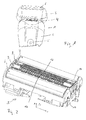
- Fig. 2 gives an enlarged perspective top view of the shaver head 3 depicting all the four cutting units which are the first foil-type cutting unit 6, the second foil-type cutting unit 7, the first trimmer-type cutting unit 8 and the second trimmer-type cutting unit 9.
- the two foil-type cutting units 6, 7 are identical while the two trimmer-type cutting units 8, 9 differ from each other in their design.
- the foil-type cutting units might be of different size, shape or may have different perforations.
- All the four cutting units are floatably mounted on a base element 10 and each cutter unit consists of an inner and an outer cutter which are - as known per se - arranged to be moved in sliding contact relative to each other and are driven by the electric motor and/or appropriate coupling elements, respectively.
- All the four cutting units are elongated along their longitudinal axis X over a length of about 45 mm and arranged in parallel along this axis X.
- the width of each trimmer-type cutting unit 8, 9 is about 5.5 mm and the width of each of the two foil-type cutting units 6, 7 is about 8 mm.
- the two trimmer-type cutting units 8, 9 are arranged in-between the two foil-type cutting units 6, 7.
- Both foil-type cutting units 6, 7 are composed of a shaving foil 11 acting as outer cutter and a cutting block 12 acting as inner cutter.
- the shaving foils 11 are hemi-spherically formed and are arranged the longitudinal axis X. They are perforated by the plurality of holes which in total build up a hole pattern in a way known per se.
- the cutting block 12 consists of a number of curved blades 13 mounted on a carrier 14, whereby this technique is per se known from the prior art cited above.
- the cutter block 12 is preloaded by a spring 15 which is supported by the base element 10 and biases the cutting block 12 permanently against the shaving foil 11.
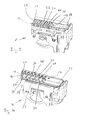
- the two trimmer-type cutting units 8, 9 each comprise completely different outer cutters 16, 17. Additionally, the first trimmer-type cutting unit 8 is carrying a guard element 18 which is provided on its longitudinal side (X) which is next to the second foil-type cutting unit 7.
- the U-shaped inner cutters 19, 20 of the first and second trimmer-type cutting units 8 and 9 are very similar to each other and differ essentially only in the pitch of the cutting bars, whereby the pitch of the cutting bars of the first trimmer-type cutting unit 8 is much smaller than the pitch of the cutting bars of the second trimmer-type cutting unit 9.
- the outer cutter 16 of the first trimmer-type cutting unit 8 comprises a plurality of bars 21 regularly disposed by a certain distance to define slots 22 in-between two adjacent bars.
- the first trimmer-type cutting unit 8 is described in more detail in the WO2010/025902 A1 .
- the bars 21 extend along the lateral axis Y which is perpendicular to the oscillating direction of the undercutters.
- the slots 22 extend entirely across the complete width of the outer cutter 16.
- the bars 21 are curved inwardly so that their outer borders 23 are provided at a higher level as their mid 24. This results in a concave top surface when looking at a cross-section parallel to the extension of the bars 21. As can be seen in Figs.
- the bars 21 comprise a higher thickness in the area of the outer borders 23 in comparison to their thickness in their mid 24. This results in an optimum between the capability of feeding hairs and a close cut of captured hair by simultaneously reducing the risk of skin irritations.
- the bars 21 are providing at their lower surfaces sharp cutting edges 25 which cooperate with cutting edges arranged at the top surface of the bars of the undercutter 19.
- a second trimmer-type cutting unit 9 as shown in Fig. 5 provides an outer cutter 17 which is composed of two comb-like cutting elements, wherein the tips 26 of the respective teeth 27 are facing each other with an offset along the longitudinal axis Z of the first row 28 of teeth 27 in relation to the second row 29 of teeth 27.
- the amount of this longitudinal shift is about half of the pitch of the teeth 27 which is identical for both comb-like cutting elements and defined by the distance between two adjacent tips 26 arranged in one row 28, 29.
- a tip 26 of one row 28, 29 of teeth 27 is directly facing the slit 30 of the opposite comb-like cutting element.
- the teeth 27 of each row are interconnected along the outer border of the second trimmer-type cutting unit 9, each by a conjunction bar 31 which extends along the longitudinal axis X.
- the teeth 27 are arranged in a way that their tips 26 are at a lightly higher vertical level (vertical axis Z) than the conjunction bars 31.
- This feature is produced by bending the outer cutter 17 along the longitudinal symmetry axis 32 which gives the whole outer cutter 17 a roof-shaped contour with a surface that increases in vertical direction from both outer borders 23 to the longitudinal symmetry axis 32.
- the increased tips 26 of the teeth 27 promote the lifting of hairs lying flat to the skin by deforming the skin and applying a contact force to the skin.
- the undercutter 20 of the second trimmer-type cutting unit 9 has a U-shaped profile and it encompasses bars 33 which are disposed in regular distances of about 1.5 mm.
- the bars 33 are providing cutting edges on their top surface which interact with the cutting edges 34 arranged on the lower surface of the teeth 27.
- Fig. 5 shows a cross-section through a shaving head 3 along a Y-Z plane. It shows working conditions where all the four cutting units 6 to 9 are depressed to the maximum into the direction to the base element 10 by compressing the springs 15 of the two foil-type cutting units and the springs 35 of the two trimmer-type cutting units 8, 9. In this state the two trimmer-type cutting units 8, 9 are lowered by a small amount (A2 is about 1 mm) in relation to the foil-type cutting units 6, 7. This condition occurs when pressing the shaving head 3 strongly to the skin and the difference A2 ensures an optimal contact of the two foil-type cutting units 6, 7 to the skin and a maximum wrapping of the shaving foils 11 by the skin.
- A2 is about 1 mm
- Fig. 6 there is shown a condition of a shaving head 3 where all four cutting units 6 to 9 are at their maximum exposure which condition will happen when the shaver is applied to the skin with only minor pressure.
- the two trimmer-type cutting units 8 and 9 are raised above the shaving foils 11 by a value A1 of up to about 2 mm.
- the exposed position of the two trimmer-type cutting 8, 9 ensures an optimal effectiveness with respect to optimal feeding and/or lifting of hairs which are lying flat to the skin.
- a guard element 18 which extends along the longitudinal axis X and is formed like a rod with a round cross-section. It is arranged at the first trimmer-type cutting unit 8 at its side which is adjacent to the second foil-type cutting unit 7. Its function to protect the skin from being captured in the slots 22 is most important under operation conditions as depicted in Fig. 6 where the cutting unit 8 is protruding the cutting unit 7.
- the base element 10 provides an upper stop 36 and a lower stop 37 to limit the floating travel of the foil-type cutting units 6 and 7.
- the upper and the lower stops 36 and 37 interact with flaps 48 provided at the outer sidewalls of the foil-type cutting units 6 and 7.
- the first trimmer-type cutting 8 provides a coupling tap 40 which protrudes into the slit 38 arranged at the inner sidewall of the first foil-type cutting unit 6.
- the horizontal slit 38 comprises an upper and a lower stop for the coupling tap 40. Due to this coupling, the difference of the horizontal level of the two cutting units 7 and 8 are limited to the amount defined by the distance between the two stops of the slit 38.
- Fig. 6 is showing the maximum difference which is A1.
- the coupling tap 40 is at the upper stop of the slit 38.
- the second trimmer-type cutting unit 9 is coupled with a limited range of travel with the first foil-type cutting unit 6 via a coupling tap 41 which protrudes into the slit 39.
- a coupling tap 42 at the right sidewall of the second trimmer-type cutting unit 9 which protrudes into the slit 43 provided in the left sidewall of the first trimmer-type cutting unit 8.
- the slit 43 defines an upper and a lower stop for the respective coupling tap 42.
- Fig. 5 also shows the drives pins 44 to 47 which are coupled in a manner known per se (not depicted in the drawing) to the electric motor to drive the undercutters of the four cutting units 6 to 9.
Landscapes
- Life Sciences & Earth Sciences (AREA)
- Forests & Forestry (AREA)
- Engineering & Computer Science (AREA)
- Mechanical Engineering (AREA)
- Dry Shavers And Clippers (AREA)
Abstract
Description
- This invention relates to a shaving head for an electric dry shaver according to the generic part of claim 1. It is especially directed to dry shavers having a shaving head with multiple cutting units.
- Shaving heads of the type initially referred to are known for example from
EP 0693988 B1 . This document discloses an electric dry shaver where a center trimmer is arranged between two foil type shaving elements. The upper cutter of this center trimmer is provided with hair feeding means consisting of projecting teeth which are directed outwardly. Those center trimmers in general are rather effective in cutting the hairs to a very short remaining length of hair. With respect to hairs which are resting flat against the skin the performance of the known cutting system is not optimal since such hairs - especially if they are located on skin areas with flexible skin - tend to escape from the feeding area formed between two teeth of the comb-shaped feeding means. - From the
EP 1930135 A1 there is known a shaving head with three foil-type cutters and a center trimmer which comprises a multiplicity of bars arranged at a small distance to each other, so as to form small slits between the bars. Such kinds of center trimmers are a more open construction without a center bar arranged along the longitudinal axis of the trimmer. Cutting units of this type have proven to be mechanically stable even with a small thickness of the outer cutter. The drawback of this kind of shaving units is the risk to cause skin irritations. The center trimmer according to theEP 1930135 A1 acts to the hairs like an expanded comb when moved during a shaving stroke along the skin. The hairs will then be directed accordingly. However, hairs to be cut have to pass completely through the height of the outer cutter of the center trimmer which most likely will not happen to hairs lying flat to the skin. - It is therefore an objective of the present invention to overcome all the drawbacks of the known shaving systems as specially such as discussed above and to provide an improved shaving head for electric shavers of the type initially referred to such to ensure an optimal shaving quality, especially when shaving hairs lying flat to the skin in both skin regions with high flexibility as well as skin regions with minor flexibility, whereby the shaving will provide an extremely high closeness as well as it avoids skin irritations.
- This objective is accomplished by the combination of features as indicated in claim 1.
- The shaving head according to the invention comprises two different kinds of trimmer-type cutters, a first trimmer-type cutting unit having an outer cutter that comprises a plurality of slots defined by a plurality of adjacent bar elements featuring cutting edges, and a second trimmer-type cutting unit having an outer cutter that comprises a plurality of teeth featuring cutting edges and spaced from each other to define a plurality of slits. Together with the at least one foil-type cutting unit they deliver a shaving performance with an additional synergistic effect when performing as a system of coordinated components and fine tuned cutting units. This results in an outstanding closeness of the shave because the shaving head according to the invention during one shaving stroke stretches the skin, lifts tricky and flat lying hairs regardless whether they grow on highly flexible skin areas or on less flexible skin areas and captures hairs growing in different directions while being gentle to the skin and avoiding skin irritations.
- In a preferred embodiment of the invention there is provided a further cutting unit of the foil type and that the two trimmer-type cutting units are arranged between the two foil-type cutting units. This ensures an optimal contact and adaptation of the shaving head to the skin independent of the skin contour. It further helps to provide optimal stretch to the skin and additionally makes the shaving result independent of the direction of the stroke. More over it helps to control the skin wave produced in front of the shaving head and between the different cutting units during a shaving stroke. The adaptability is even improved when the cutting units are mounted on the base element in a floatable manner in the vertical direction. However, also other combinations or arrangements of the four cutting units on the base element are within the scope of the invention. In an embodiment where the cutting units are interconnected with vertical play via coupling elements it is ensured that difference of exposure of single cutting units - especially of the trimmer-type cutting units - is limited, which has a positive effect to the avoidance of skin irritations since the trimmer-type cutting units are thereby always slightly covered by the foil-type cutting units which is consequently protecting the skin. The limitation of the exposure prevents too excessive skin deformations in front of the center-trimmers, which has a positive effect to the avoidance of skin irritations. The skin protection can even be improved if a skin protecting guard element is arranged between the first trimmer-type cutting unit and the adjacent foil-type cutting unit. In a preferred embodiment the guard element is fixed to the first trimmer-type cutting unit.
- A particularly effective lifting of flat lying hairs during a shaving stroke is achieved if the outer cutter of the foil-type cutting unit is shaped essentially semi-cylindrically along its longitudinal axis and that at least one of the trimmer-type cutting units comprises a top surface which is not plane. This geometry of surfaces applies a deformation to the skin during shaving which exposes a force or a moment to the hair which can help raising hairs lying flat to the skin. That effect can be enhanced if the first trimmer-type cutting unit provides a concave top surface and the second trimmer-type cutting unit has a convex or a roof-shaped surface. However, especially the second trimmer-type cutting unit might also be providing a flat surface to contact the skin.
- To reach a maximum of feeding performance a further version of the invention provides that the outer cutter of the second trimmer-type cutting unit comprises two comb elements disposed opposite one another, whereby the teeth of the first comb element are facing the teeth of the second comb element. Especially the teeth of the comb elements extend along the lateral axis and are angled with respect to the horizontal plane such that their tips are elevated.
- The invention will be further elucidated by detailed explanation of exemplary embodiments and by reference to figures. In the figures
- Fig. 1
- is an illustration of an electric shaver,
- Fig. 2
- is a perspective illustration of an exemplary embodiment of the invention,
- Fig. 3
- is an enlarged illustration of the first trimmer-type cutting unit according to the invention,
- Fig. 4
- is an enlarged illustration of the second trimmer-type cutting unit according to the invention,
- Fig. 5
- is a schematic depiction of a cross-section through a shaver head according to the invention where the cutting units are depressed to the basis, and
- Fig. 6
- shows a schematic cross-section through the shaving head where all cutting units are free of external load.
-
Fig. 1 shows an illustration of an electric shaver in general. It essentially consists of ahousing 2 carrying at its top a shavinghead 3 and at the front part of the housing 2 a long-hair clipper 4. Inside thehousing 2 there is arranged an electric motor for driving all the cutting parts when the shaver is switched on via the ON/OFF switch 5. The electric motor is not shown in the drawing. -
Fig. 2 gives an enlarged perspective top view of theshaver head 3 depicting all the four cutting units which are the first foil-type cutting unit 6, the second foil-type cutting unit 7, the first trimmer-type cutting unit 8 and the second trimmer-type cutting unit 9. According to this embodiment the two foil-type cutting units type cutting units base element 10 and each cutter unit consists of an inner and an outer cutter which are - as known per se - arranged to be moved in sliding contact relative to each other and are driven by the electric motor and/or appropriate coupling elements, respectively. All the four cutting units are elongated along their longitudinal axis X over a length of about 45 mm and arranged in parallel along this axis X. The width of each trimmer-type cutting unit type cutting units type cutting units type cutting units type cutting units block 12 acting as inner cutter. The shaving foils 11 are hemi-spherically formed and are arranged the longitudinal axis X. They are perforated by the plurality of holes which in total build up a hole pattern in a way known per se. During a shave stroke the hairs are introduced into and through the holes of the shaving foil to be then cut by the cutting block 12 (seeFigs. 5 and 6 ) which is arranged underneath the shaving foil 11 and moved relatively to the shaving foil 11 in sliding contact. The cuttingblock 12 consists of a number ofcurved blades 13 mounted on acarrier 14, whereby this technique is per se known from the prior art cited above. Thecutter block 12 is preloaded by aspring 15 which is supported by thebase element 10 and biases the cuttingblock 12 permanently against the shaving foil 11. - As can be taken from the
Figs. 2 to 4 , the two trimmer-type cutting units outer cutters type cutting unit 8 is carrying aguard element 18 which is provided on its longitudinal side (X) which is next to the second foil-type cutting unit 7. The U-shapedinner cutters type cutting units type cutting unit 8 is much smaller than the pitch of the cutting bars of the second trimmer-type cutting unit 9. - As can be taken best from
Fig. 3 , theouter cutter 16 of the first trimmer-type cutting unit 8 comprises a plurality of bars 21 regularly disposed by a certain distance to define slots 22 in-between two adjacent bars. The first trimmer-type cutting unit 8 is described in more detail in theWO2010/025902 A1 . The bars 21 extend along the lateral axis Y which is perpendicular to the oscillating direction of the undercutters. The slots 22 extend entirely across the complete width of theouter cutter 16. The bars 21 are curved inwardly so that theirouter borders 23 are provided at a higher level as their mid 24. This results in a concave top surface when looking at a cross-section parallel to the extension of the bars 21. As can be seen inFigs. 5 and 6 , the bars 21 comprise a higher thickness in the area of theouter borders 23 in comparison to their thickness in their mid 24. This results in an optimum between the capability of feeding hairs and a close cut of captured hair by simultaneously reducing the risk of skin irritations. In a manner known per se the bars 21 are providing at their lower surfaces sharp cutting edges 25 which cooperate with cutting edges arranged at the top surface of the bars of theundercutter 19. - A second trimmer-
type cutting unit 9 as shown inFig. 5 provides anouter cutter 17 which is composed of two comb-like cutting elements, wherein thetips 26 of therespective teeth 27 are facing each other with an offset along the longitudinal axis Z of thefirst row 28 ofteeth 27 in relation to thesecond row 29 ofteeth 27. The amount of this longitudinal shift is about half of the pitch of theteeth 27 which is identical for both comb-like cutting elements and defined by the distance between twoadjacent tips 26 arranged in onerow tip 26 of onerow teeth 27 is directly facing theslit 30 of the opposite comb-like cutting element. Theteeth 27 of each row are interconnected along the outer border of the second trimmer-type cutting unit 9, each by aconjunction bar 31 which extends along the longitudinal axis X. Theteeth 27 are arranged in a way that theirtips 26 are at a lightly higher vertical level (vertical axis Z) than the conjunction bars 31. This feature is produced by bending theouter cutter 17 along thelongitudinal symmetry axis 32 which gives the whole outer cutter 17 a roof-shaped contour with a surface that increases in vertical direction from bothouter borders 23 to thelongitudinal symmetry axis 32. The increasedtips 26 of theteeth 27 promote the lifting of hairs lying flat to the skin by deforming the skin and applying a contact force to the skin. In comparison to the conjunction bars 31 thetips 26 are increased in an amount of around 0.25 mm, which gives the best compromise between optimal lifting of hairs and gentleness to the skin. The distance betweenopposite tips 26 is about 1 mm. The pitch of the row ofteeth 27 is about 0.9 mm. Theundercutter 20 of the second trimmer-type cutting unit 9 has a U-shaped profile and it encompassesbars 33 which are disposed in regular distances of about 1.5 mm. Thebars 33 are providing cutting edges on their top surface which interact with the cutting edges 34 arranged on the lower surface of theteeth 27. -
Fig. 5 shows a cross-section through a shavinghead 3 along a Y-Z plane. It shows working conditions where all the fourcutting units 6 to 9 are depressed to the maximum into the direction to thebase element 10 by compressing thesprings 15 of the two foil-type cutting units and thesprings 35 of the two trimmer-type cutting units type cutting units type cutting units shaving head 3 strongly to the skin and the difference A2 ensures an optimal contact of the two foil-type cutting units - In
Fig. 6 there is shown a condition of ashaving head 3 where all fourcutting units 6 to 9 are at their maximum exposure which condition will happen when the shaver is applied to the skin with only minor pressure. Under these circumstances the two trimmer-type cutting units - Since the slots 22 of the
outer cutter 16 are opened sidewardly at theirouter borders 23, it can occur under certain conditions that skin can be captured by and penetrate into the slots 22 during a shaving stroke. To avoid this penetration which could lead to skin irritations, there is arranged aguard element 18 which extends along the longitudinal axis X and is formed like a rod with a round cross-section. It is arranged at the first trimmer-type cutting unit 8 at its side which is adjacent to the second foil-type cutting unit 7. Its function to protect the skin from being captured in the slots 22 is most important under operation conditions as depicted inFig. 6 where thecutting unit 8 is protruding thecutting unit 7. Especially these working conditions bear the risk for skin to be captured in the slots 22 because of the fact that the free distance between theouter cutter 16 and the shaving foil 11 is at its maximum value, which might allow a skin wave to be pressed into that gap. However also under the other shaving conditions is theguard element 18 is beneficial for avoiding irritation of the skin. It is not necessary to have aguard element 18 at the opposite side of thecutting unit 8 because the protection function is delivered by thecutting unit 9 which provides aconjunction bar 31 that is located next to theouter cutter 16. - The
base element 10 provides anupper stop 36 and alower stop 37 to limit the floating travel of the foil-type cutting units flaps 48 provided at the outer sidewalls of the foil-type cutting units coupling tap 40 which protrudes into theslit 38 arranged at the inner sidewall of the first foil-type cutting unit 6. Thehorizontal slit 38 comprises an upper and a lower stop for thecoupling tap 40. Due to this coupling, the difference of the horizontal level of the two cuttingunits slit 38. -
Fig. 6 is showing the maximum difference which is A1. As can be taken fromFig. 6 , thecoupling tap 40 is at the upper stop of theslit 38. In an analog manner the second trimmer-type cutting unit 9 is coupled with a limited range of travel with the first foil-type cutting unit 6 via acoupling tap 41 which protrudes into theslit 39. To limit the difference in horizontal level between the trimmer-type cutting units coupling tap 42 at the right sidewall of the second trimmer-type cutting unit 9 which protrudes into theslit 43 provided in the left sidewall of the first trimmer-type cutting unit 8. Also theslit 43 defines an upper and a lower stop for therespective coupling tap 42. Due to the coupling between the fourcutting units 6 to 9 via the coupling taps 40 to 42, all the four cutting units are still floatable independently but the difference in the vertical level between single cutting units is limited. This is provided to ensure a maximum of skin friendliness and to additionally provide the best contact between the outer cutters of the four cutting units to the skin. -
Fig. 5 also shows the drives pins 44 to 47 which are coupled in a manner known per se (not depicted in the drawing) to the electric motor to drive the undercutters of the fourcutting units 6 to 9. - The dimensions and values disclosed herein are not to be understood as being strictly limited to the exact numerical values recited. Instead, unless otherwise specified, each such dimension is intended to mean both the recited value and a functionally equivalent range surrounding that value. For example, a dimension disclosed as "40 mm" is intended to mean "about 40 mm."
Claims (10)
- A shaving head (3) for an electric dry shaver (1), comprising a base element (10) for carrying at least three cutter units each providing an outer cutter and inner cutter arranged to be moved in sliding contact relative to each other, whereby at least one cutter unit comprises a foil-type outer cutter (11), characterized in that the shaving head (3) further comprises a first trimmer-type cutting unit (8) having an outer cutter (16) that comprises a plurality of slots (22) defined by a plurality of adjacent bar elements (21) featuring cutting edges (25), and a second trimmer-type cutting unit (9) having an outer cutter (17) that comprises a plurality of teeth (27) featuring cutting edges (34) and spaced from each other to define a plurality of slits (30).
- The shaving head as claimed in claim 1, characterized in that there is provided a further cutting unit of the foil type and that the two trimmer-type cutting units (8, 9) are arranged between the two foil-type cutting (6, 7) units.
- The shaving head as claimed in any one of the preceding claims, characterized in that the cutting units (6-9) are mounted on the base element (10) in a floatable manner in the vertical direction (Z).
- The shaving head as claimed in claim 3, characterized in that the cutting units (6 - 9) are interconnected with vertical play via coupling elements (38 - 44).
- The shaving head as claimed in any one of the preceding claims, characterized in that a skin protecting guard element (18) is arranged between the first trimmer-type cutting unit (8) and the adjacent foil-type cutting unit (7).
- The shaving head as claimed in claim 5, characterized in that the guard element (18) is fixed to the first trimmer-type cutting unit (8).
- The shaving head as claimed in any one of the preceding claims, characterized in that the outer cutter (11) of the foil-type cutting unit (6, 7) is shaped essentially semi-cylindrically along its longitudinal axis (X) and that at least one of the trimmer-type cutting units (8,9) comprises a top surface which is not plane.
- The shaving head as claimed in claim 7, characterized in that the first trimmer-type cutting (8) unit provides a concave top surface and the second trimmer-type cutting unit (9) has a convex or a roof-shaped surface.
- The shaving head as claimed in any one of the preceding claims, characterized in that the outer cutter (17) of the second trimmer-type cutting unit (9) comprises two comb elements disposed opposite one another, whereby the teeth (27) of the first comb element (28) are facing the teeth (27) of the second comb element (29).
- The shaving head as claimed in claim 9, characterized in that the teeth (27) of the comb elements extend along the lateral axis (Y) and are angled with respect to the horizontal plane (X-Y) such that their tips (26) are elevated.
Priority Applications (7)
| Application Number | Priority Date | Filing Date | Title |
|---|---|---|---|
| EP10009208.9A EP2425938B1 (en) | 2010-09-03 | 2010-09-03 | Shaving head with multiple shaving units |
| US13/193,648 US9592613B2 (en) | 2010-09-03 | 2011-07-29 | Shaving head with multiple shaving units |
| RU2013106949/02A RU2539257C2 (en) | 2010-09-03 | 2011-08-31 | Shaving head with multiple shaving assemblies |
| CN201180042357.0A CN103079779B (en) | 2010-09-03 | 2011-08-31 | Shaving head with several shaving units |
| JP2013526585A JP2013536055A (en) | 2010-09-03 | 2011-08-31 | Shaving head with multiple shaving units |
| PCT/IB2011/053825 WO2012029043A1 (en) | 2010-09-03 | 2011-08-31 | Shaving head with multiple shaving units |
| JP2015101198A JP6017626B2 (en) | 2010-09-03 | 2015-05-18 | Shaving head with multiple shaving units |
Applications Claiming Priority (1)
| Application Number | Priority Date | Filing Date | Title |
|---|---|---|---|
| EP10009208.9A EP2425938B1 (en) | 2010-09-03 | 2010-09-03 | Shaving head with multiple shaving units |
Publications (2)
| Publication Number | Publication Date |
|---|---|
| EP2425938A1 true EP2425938A1 (en) | 2012-03-07 |
| EP2425938B1 EP2425938B1 (en) | 2014-02-26 |
Family
ID=43481023
Family Applications (1)
| Application Number | Title | Priority Date | Filing Date |
|---|---|---|---|
| EP10009208.9A Active EP2425938B1 (en) | 2010-09-03 | 2010-09-03 | Shaving head with multiple shaving units |
Country Status (6)
| Country | Link |
|---|---|
| US (1) | US9592613B2 (en) |
| EP (1) | EP2425938B1 (en) |
| JP (2) | JP2013536055A (en) |
| CN (1) | CN103079779B (en) |
| RU (1) | RU2539257C2 (en) |
| WO (1) | WO2012029043A1 (en) |
Cited By (14)
| Publication number | Priority date | Publication date | Assignee | Title |
|---|---|---|---|---|
| EP3300859A1 (en) * | 2016-09-28 | 2018-04-04 | Braun GmbH | Beard trimmer |
| EP3300847A1 (en) * | 2016-09-28 | 2018-04-04 | Braun GmbH | Beard trimmer |
| US10792824B2 (en) | 2016-09-28 | 2020-10-06 | Braun Gmbh | Beard trimmer |
| US10906195B2 (en) | 2016-09-28 | 2021-02-02 | Braun Gmbh | Beard trimmer |
| EP3854544A1 (en) | 2020-01-23 | 2021-07-28 | Braun GmbH | Electric beard trimmer |
| EP3854547A1 (en) | 2020-01-23 | 2021-07-28 | Braun GmbH | Electric beard trimmer |
| EP3854539A1 (en) | 2020-01-23 | 2021-07-28 | Braun GmbH | Electric beard trimmer |
| WO2021149026A1 (en) | 2020-01-23 | 2021-07-29 | Braun Gmbh | Electric beard trimmer |
| EP3907045A1 (en) | 2020-05-08 | 2021-11-10 | Braun GmbH | Electric beard trimmer |
| EP3907043A1 (en) | 2020-05-08 | 2021-11-10 | Braun GmbH | Electric beard trimmer |
| US20220314473A1 (en) * | 2021-03-30 | 2022-10-06 | Panasonic Intellectual Property Management Co., Ltd. | Blade unit and electric razor |
| WO2023286011A1 (en) | 2021-07-15 | 2023-01-19 | Braun Gmbh | Cutter system for an electric beard trimmer |
| EP4241937A1 (en) | 2022-03-10 | 2023-09-13 | Braun GmbH | Electric beard trimmer |
| EP4763446A1 (en) | 2024-12-17 | 2026-06-24 | Braun GmbH | Electric hair cutter |
Families Citing this family (23)
| Publication number | Priority date | Publication date | Assignee | Title |
|---|---|---|---|---|
| DE102008048725A1 (en) * | 2008-09-24 | 2010-03-25 | Braun Gmbh | Hair removal device with skin preparation device |
| EP2425939B1 (en) * | 2010-09-03 | 2014-06-11 | Braun GmbH | Shaving unit for an electric shaver |
| JP6376427B2 (en) * | 2012-12-27 | 2018-08-22 | パナソニックIpマネジメント株式会社 | Slit blade block and electric razor having slit blade block |
| EP2857155A1 (en) * | 2013-10-01 | 2015-04-08 | Koninklijke Philips N.V. | Blade set and hair cutting appliance |
| EP2857158B1 (en) * | 2013-10-01 | 2017-05-10 | Koninklijke Philips N.V. | Blade set and hair cutting appliance |
| JP6284792B2 (en) * | 2014-03-13 | 2018-02-28 | マクセルホールディングス株式会社 | Electric razor |
| WO2016041959A1 (en) * | 2014-09-18 | 2016-03-24 | Koninklijke Philips N.V. | Cutting head and hair cutting appliance |
| JP6440117B2 (en) * | 2015-03-06 | 2018-12-19 | パナソニックIpマネジメント株式会社 | Electric razor and its head |
| US10828793B2 (en) * | 2015-04-15 | 2020-11-10 | Rk Inventions, Llc | Razor assembly |
| US9829698B2 (en) | 2015-08-31 | 2017-11-28 | Panasonic Corporation | Endoscope |
| EP3238895B1 (en) * | 2016-04-27 | 2019-01-23 | Braun GmbH | Blade, shaver with a blade and method for producing a blade |
| EP3300861B1 (en) | 2016-09-28 | 2019-07-03 | Braun GmbH | Electrically driven device |
| EP3300844B1 (en) * | 2016-09-28 | 2020-04-15 | Braun GmbH | Electric shaver |
| EP3300860B1 (en) * | 2016-09-28 | 2019-10-30 | Braun GmbH | Beard trimmer |
| EP3546146B1 (en) * | 2018-03-27 | 2021-08-18 | Braun GmbH | Hair removal device |
| CN110181565A (en) * | 2019-06-26 | 2019-08-30 | 温州市日电电器有限公司 | A kind of razor tool tip and its binding face baffle |
| JP1654722S (en) * | 2019-08-26 | 2020-03-09 | Electric shaver | |
| EP3907048B1 (en) | 2020-05-08 | 2023-03-22 | Braun GmbH | Electric beard trimmer |
| EP3907049B1 (en) | 2020-05-08 | 2023-03-22 | Braun GmbH | Electric beard trimmer |
| JP7702620B2 (en) * | 2021-03-30 | 2025-07-04 | パナソニックIpマネジメント株式会社 | Blade unit and electric shaver |
| JP7576775B2 (en) * | 2021-03-30 | 2024-11-01 | パナソニックIpマネジメント株式会社 | Comb-shaped outer blade, blade unit, and electric shaver |
| EP4124419B1 (en) * | 2021-07-29 | 2025-07-16 | Braun GmbH | Hair removal device |
| EP4670931A1 (en) | 2024-06-28 | 2025-12-31 | Braun GmbH | ELECTRIC SHAVER AND UNDERBINDER FOR IT |
Citations (11)
| Publication number | Priority date | Publication date | Assignee | Title |
|---|---|---|---|---|
| US2298962A (en) * | 1939-05-10 | 1942-10-13 | Thomas J Murphy | Dry shaver |
| US2859513A (en) * | 1956-06-28 | 1958-11-11 | Schick Inc | Electric shaver shearing head assembly |
| DE1111062B (en) * | 1959-06-05 | 1961-07-13 | Siemens Ag | Dry shaver with two parallel shaving heads |
| US4081902A (en) * | 1976-12-07 | 1978-04-04 | Sperry Rand Corporation | Cutter head assembly for an electric dry shaver |
| DE2841692A1 (en) * | 1978-09-25 | 1980-04-03 | Rian Gmbh Apparate U Geraeteba | Electric shaver with attachment for cutting long hair - has two sets of blades for cutting hair in two stages |
| US4274199A (en) * | 1979-01-02 | 1981-06-23 | Sunbeam Corporation | Electric shaver |
| EP0693988B1 (en) | 1993-04-13 | 1996-12-11 | Braun Aktiengesellschaft | Shaving head for electric razors |
| US20040055158A1 (en) * | 2002-09-19 | 2004-03-25 | Izumi Products Company | Electric shaver |
| US20050016002A1 (en) * | 2003-07-22 | 2005-01-27 | Matsushita Electric Works, Ltd., | Electric shaver |
| EP1930135A1 (en) | 2006-12-08 | 2008-06-11 | Matsushita Electric Works, Ltd. | Dry shaver |
| WO2010025902A1 (en) | 2008-09-05 | 2010-03-11 | Braun Gmbh | Cutting head for a razor |
Family Cites Families (27)
| Publication number | Priority date | Publication date | Assignee | Title |
|---|---|---|---|---|
| US2240264A (en) | 1936-12-31 | 1941-04-29 | Gillette Safety Razor Co | Shaving implement |
| US2279102A (en) * | 1939-10-25 | 1942-04-07 | Altemus James Dobson | Electric razor |
| US2325267A (en) * | 1940-09-27 | 1943-07-27 | Thomas J Murphy | Dry shaver cutter head |
| US2331274A (en) * | 1941-11-14 | 1943-10-05 | Martin Brothers Electric Compa | Dry shaver |
| US2706332A (en) * | 1951-11-07 | 1955-04-19 | Murphy Mary Louise | Dry shaver cutter head |
| US2915816A (en) * | 1958-11-20 | 1959-12-08 | Schick Inc | Electric shaver inner cutter |
| JPS4528337Y1 (en) * | 1969-01-19 | 1970-10-31 | ||
| GB2057333B (en) | 1979-08-07 | 1982-12-15 | Matsushita Electric Works Ltd | Shaving blade assembly |
| RU2103158C1 (en) * | 1995-10-12 | 1998-01-27 | Акционерное общество открытого типа Бердский электромеханический завод | Shearing head of electric razor |
| KR100415352B1 (en) * | 1996-05-29 | 2004-06-30 | 산요덴키가부시키가이샤 | Electric Shaver |
| GB9614160D0 (en) * | 1996-07-05 | 1996-09-04 | Gillette Co | Dry shaving apparatus |
| CN1129510C (en) * | 1997-02-17 | 2003-12-03 | 皇家菲利浦电子有限公司 | Shaver |
| JPH10323462A (en) * | 1997-05-27 | 1998-12-08 | Matsushita Electric Works Ltd | Reciprocating electric razor |
| JP3814965B2 (en) * | 1997-07-28 | 2006-08-30 | 松下電工株式会社 | Reciprocating electric razor |
| JP3045934U (en) * | 1997-08-04 | 1998-02-20 | 清川 陳 | Intermediate head of electric shaver |
| KR100543557B1 (en) * | 1997-10-30 | 2007-04-25 | 산요덴키가부시키가이샤 | Electric shaver |
| JP3747620B2 (en) * | 1998-03-26 | 2006-02-22 | 松下電工株式会社 | Reciprocating electric razor |
| JP2000084270A (en) * | 1998-09-09 | 2000-03-28 | Sanyo Electric Co Ltd | Reciprocating electric razor |
| US6931731B2 (en) * | 2002-05-27 | 2005-08-23 | Izumi Products Company | Electric shaver |
| DE10344566A1 (en) * | 2003-09-25 | 2005-04-28 | Braun Gmbh | Trimming system for an electrical hair removal appliance, especially an electrical shaving appliance, comprises a trimming unit provided with an upper blade and a lower blade, and a supply unit displaced in relation to the upper blade |
| AT502726A1 (en) * | 2004-12-15 | 2007-05-15 | Payer Int Technologies Gmbh | RAZOR AND HAIR CUTTING DEVICE |
| JP4552646B2 (en) * | 2004-12-16 | 2010-09-29 | パナソニック電工株式会社 | Hair removal equipment |
| JP4725103B2 (en) * | 2004-12-28 | 2011-07-13 | パナソニック電工株式会社 | Reciprocating electric razor |
| DE102006030946A1 (en) * | 2006-07-05 | 2008-01-10 | Braun Gmbh | Shaving unit for a dry shaver |
| JP4462261B2 (en) * | 2006-12-08 | 2010-05-12 | パナソニック電工株式会社 | Electric razor |
| JP4396695B2 (en) * | 2006-12-08 | 2010-01-13 | パナソニック電工株式会社 | Electric razor |
| CN101678556B (en) | 2007-06-13 | 2013-08-14 | 皇家飞利浦电子股份有限公司 | Shaving apparatus, cutting unit and shaving head support |
-
2010
- 2010-09-03 EP EP10009208.9A patent/EP2425938B1/en active Active
-
2011
- 2011-07-29 US US13/193,648 patent/US9592613B2/en active Active
- 2011-08-31 WO PCT/IB2011/053825 patent/WO2012029043A1/en not_active Ceased
- 2011-08-31 RU RU2013106949/02A patent/RU2539257C2/en not_active IP Right Cessation
- 2011-08-31 CN CN201180042357.0A patent/CN103079779B/en active Active
- 2011-08-31 JP JP2013526585A patent/JP2013536055A/en active Pending
-
2015
- 2015-05-18 JP JP2015101198A patent/JP6017626B2/en active Active
Patent Citations (11)
| Publication number | Priority date | Publication date | Assignee | Title |
|---|---|---|---|---|
| US2298962A (en) * | 1939-05-10 | 1942-10-13 | Thomas J Murphy | Dry shaver |
| US2859513A (en) * | 1956-06-28 | 1958-11-11 | Schick Inc | Electric shaver shearing head assembly |
| DE1111062B (en) * | 1959-06-05 | 1961-07-13 | Siemens Ag | Dry shaver with two parallel shaving heads |
| US4081902A (en) * | 1976-12-07 | 1978-04-04 | Sperry Rand Corporation | Cutter head assembly for an electric dry shaver |
| DE2841692A1 (en) * | 1978-09-25 | 1980-04-03 | Rian Gmbh Apparate U Geraeteba | Electric shaver with attachment for cutting long hair - has two sets of blades for cutting hair in two stages |
| US4274199A (en) * | 1979-01-02 | 1981-06-23 | Sunbeam Corporation | Electric shaver |
| EP0693988B1 (en) | 1993-04-13 | 1996-12-11 | Braun Aktiengesellschaft | Shaving head for electric razors |
| US20040055158A1 (en) * | 2002-09-19 | 2004-03-25 | Izumi Products Company | Electric shaver |
| US20050016002A1 (en) * | 2003-07-22 | 2005-01-27 | Matsushita Electric Works, Ltd., | Electric shaver |
| EP1930135A1 (en) | 2006-12-08 | 2008-06-11 | Matsushita Electric Works, Ltd. | Dry shaver |
| WO2010025902A1 (en) | 2008-09-05 | 2010-03-11 | Braun Gmbh | Cutting head for a razor |
Cited By (37)
| Publication number | Priority date | Publication date | Assignee | Title |
|---|---|---|---|---|
| EP3300859A1 (en) * | 2016-09-28 | 2018-04-04 | Braun GmbH | Beard trimmer |
| EP3300847A1 (en) * | 2016-09-28 | 2018-04-04 | Braun GmbH | Beard trimmer |
| WO2018060894A1 (en) * | 2016-09-28 | 2018-04-05 | Braun Gmbh | Beard trimmer |
| WO2018060896A1 (en) * | 2016-09-28 | 2018-04-05 | Braun Gmbh | Beard trimmer |
| US10792824B2 (en) | 2016-09-28 | 2020-10-06 | Braun Gmbh | Beard trimmer |
| US10906195B2 (en) | 2016-09-28 | 2021-02-02 | Braun Gmbh | Beard trimmer |
| WO2021149034A1 (en) | 2020-01-23 | 2021-07-29 | Braun Gmbh | Electric beard trimmer |
| WO2021149032A1 (en) | 2020-01-23 | 2021-07-29 | Braun Gmbh | Electric beard trimmer |
| EP3854541A1 (en) | 2020-01-23 | 2021-07-28 | Braun GmbH | Electric beard trimmer |
| EP3854546A1 (en) | 2020-01-23 | 2021-07-28 | Braun GmbH | Electric beard trimmer |
| EP3854545A1 (en) | 2020-01-23 | 2021-07-28 | Braun GmbH | Electric beard trimmer |
| EP3854543A1 (en) | 2020-01-23 | 2021-07-28 | Braun GmbH | Electric beard trimmer |
| EP3854539A1 (en) | 2020-01-23 | 2021-07-28 | Braun GmbH | Electric beard trimmer |
| WO2021149031A1 (en) | 2020-01-23 | 2021-07-29 | Braun Gmbh | Electric beard trimmer |
| WO2021149030A1 (en) | 2020-01-23 | 2021-07-29 | Braun Gmbh | Electric beard trimmer |
| WO2021149029A1 (en) | 2020-01-23 | 2021-07-29 | Braun Gmbh | Electric beard trimmer |
| WO2021149033A1 (en) | 2020-01-23 | 2021-07-29 | Braun Gmbh | Electric beard trimmer |
| WO2021149026A1 (en) | 2020-01-23 | 2021-07-29 | Braun Gmbh | Electric beard trimmer |
| EP3854544A1 (en) | 2020-01-23 | 2021-07-28 | Braun GmbH | Electric beard trimmer |
| WO2021149035A1 (en) | 2020-01-23 | 2021-07-29 | Braun Gmbh | Electric beard trimmer |
| WO2021149027A1 (en) | 2020-01-23 | 2021-07-29 | Braun Gmbh | Electric beard trimmer |
| EP3854547A1 (en) | 2020-01-23 | 2021-07-28 | Braun GmbH | Electric beard trimmer |
| WO2021149028A1 (en) | 2020-01-23 | 2021-07-29 | Braun Gmbh | Electric beard trimmer |
| EP3907045A1 (en) | 2020-05-08 | 2021-11-10 | Braun GmbH | Electric beard trimmer |
| EP3907046A1 (en) | 2020-05-08 | 2021-11-10 | Braun GmbH | Electric beard trimmer |
| EP3907043A1 (en) | 2020-05-08 | 2021-11-10 | Braun GmbH | Electric beard trimmer |
| WO2021224848A1 (en) | 2020-05-08 | 2021-11-11 | Braun Gmbh | Electric beard trimmer |
| WO2021224851A1 (en) | 2020-05-08 | 2021-11-11 | Braun Gmbh | Electric beard trimmer |
| WO2021224852A1 (en) | 2020-05-08 | 2021-11-11 | Braun Gmbh | Electric beard trimmer |
| US20220314473A1 (en) * | 2021-03-30 | 2022-10-06 | Panasonic Intellectual Property Management Co., Ltd. | Blade unit and electric razor |
| US11745367B2 (en) * | 2021-03-30 | 2023-09-05 | Panasonic Intellectual Property Management Co., Ltd. | Blade unit and electric razor |
| WO2023286011A1 (en) | 2021-07-15 | 2023-01-19 | Braun Gmbh | Cutter system for an electric beard trimmer |
| EP4241937A1 (en) | 2022-03-10 | 2023-09-13 | Braun GmbH | Electric beard trimmer |
| EP4241938A1 (en) | 2022-03-10 | 2023-09-13 | Braun GmbH | Electric beard trimmer |
| WO2023170621A1 (en) | 2022-03-10 | 2023-09-14 | Braun Gmbh | Electric beard trimmer |
| EP4763446A1 (en) | 2024-12-17 | 2026-06-24 | Braun GmbH | Electric hair cutter |
| EP4763447A1 (en) | 2024-12-17 | 2026-06-24 | Braun GmbH | Electric hair cutter |
Also Published As
| Publication number | Publication date |
|---|---|
| WO2012029043A1 (en) | 2012-03-08 |
| RU2013106949A (en) | 2014-10-10 |
| RU2539257C2 (en) | 2015-01-20 |
| US9592613B2 (en) | 2017-03-14 |
| JP2015171557A (en) | 2015-10-01 |
| CN103079779A (en) | 2013-05-01 |
| JP2013536055A (en) | 2013-09-19 |
| CN103079779B (en) | 2016-10-19 |
| US20120055025A1 (en) | 2012-03-08 |
| EP2425938B1 (en) | 2014-02-26 |
| JP6017626B2 (en) | 2016-11-02 |
Similar Documents
| Publication | Publication Date | Title |
|---|---|---|
| EP2425938B1 (en) | Shaving head with multiple shaving units | |
| EP2425939B1 (en) | Shaving unit for an electric shaver | |
| EP3037223B1 (en) | Dry shaver | |
| EP2747958B1 (en) | Skin guard for hair trimmer | |
| EP4119312B1 (en) | Cutter system for an electric beard trimmer | |
| CN100579736C (en) | Razor foils for dry shavers | |
| US11794362B2 (en) | Electric beard trimmer | |
| US12384063B2 (en) | Electric beard trimmer | |
| EP2347869B1 (en) | Electric shaver | |
| CN100478144C (en) | An electrical hair removal appliance and trimming system thereof | |
| CN101195223A (en) | Dry shaver | |
| US20260001245A1 (en) | Electric shaver and shear foil cutter system thereof | |
| US20080005906A1 (en) | Electric Hair Trimmer | |
| JP2023021049A (en) | hair removal device | |
| US20240109211A1 (en) | Blade set for a hair cutting machine | |
| US20100236073A1 (en) | Electric Razors |
Legal Events
| Date | Code | Title | Description |
|---|---|---|---|
| AK | Designated contracting states |
Kind code of ref document: A1 Designated state(s): AL AT BE BG CH CY CZ DE DK EE ES FI FR GB GR HR HU IE IS IT LI LT LU LV MC MK MT NL NO PL PT RO SE SI SK SM TR |
|
| AX | Request for extension of the european patent |
Extension state: BA ME RS |
|
| PUAI | Public reference made under article 153(3) epc to a published international application that has entered the european phase |
Free format text: ORIGINAL CODE: 0009012 |
|
| 17P | Request for examination filed |
Effective date: 20120605 |
|
| 17Q | First examination report despatched |
Effective date: 20130124 |
|
| GRAP | Despatch of communication of intention to grant a patent |
Free format text: ORIGINAL CODE: EPIDOSNIGR1 |
|
| INTG | Intention to grant announced |
Effective date: 20130924 |
|
| GRAS | Grant fee paid |
Free format text: ORIGINAL CODE: EPIDOSNIGR3 |
|
| GRAA | (expected) grant |
Free format text: ORIGINAL CODE: 0009210 |
|
| AK | Designated contracting states |
Kind code of ref document: B1 Designated state(s): AL AT BE BG CH CY CZ DE DK EE ES FI FR GB GR HR HU IE IS IT LI LT LU LV MC MK MT NL NO PL PT RO SE SI SK SM TR |
|
| REG | Reference to a national code |
Ref country code: GB Ref legal event code: FG4D |
|
| REG | Reference to a national code |
Ref country code: CH Ref legal event code: NV Representative=s name: BOHEST AG, CH Ref country code: CH Ref legal event code: EP |
|
| REG | Reference to a national code |
Ref country code: AT Ref legal event code: REF Ref document number: 653275 Country of ref document: AT Kind code of ref document: T Effective date: 20140315 |
|
| REG | Reference to a national code |
Ref country code: NL Ref legal event code: T3 |
|
| REG | Reference to a national code |
Ref country code: IE Ref legal event code: FG4D |
|
| REG | Reference to a national code |
Ref country code: DE Ref legal event code: R096 Ref document number: 602010013678 Country of ref document: DE Effective date: 20140410 |
|
| REG | Reference to a national code |
Ref country code: LT Ref legal event code: MG4D |
|
| PG25 | Lapsed in a contracting state [announced via postgrant information from national office to epo] |
Ref country code: NO Free format text: LAPSE BECAUSE OF FAILURE TO SUBMIT A TRANSLATION OF THE DESCRIPTION OR TO PAY THE FEE WITHIN THE PRESCRIBED TIME-LIMIT Effective date: 20140526 Ref country code: IS Free format text: LAPSE BECAUSE OF FAILURE TO SUBMIT A TRANSLATION OF THE DESCRIPTION OR TO PAY THE FEE WITHIN THE PRESCRIBED TIME-LIMIT Effective date: 20140626 Ref country code: LT Free format text: LAPSE BECAUSE OF FAILURE TO SUBMIT A TRANSLATION OF THE DESCRIPTION OR TO PAY THE FEE WITHIN THE PRESCRIBED TIME-LIMIT Effective date: 20140226 |
|
| PG25 | Lapsed in a contracting state [announced via postgrant information from national office to epo] |
Ref country code: CY Free format text: LAPSE BECAUSE OF FAILURE TO SUBMIT A TRANSLATION OF THE DESCRIPTION OR TO PAY THE FEE WITHIN THE PRESCRIBED TIME-LIMIT Effective date: 20140226 Ref country code: SE Free format text: LAPSE BECAUSE OF FAILURE TO SUBMIT A TRANSLATION OF THE DESCRIPTION OR TO PAY THE FEE WITHIN THE PRESCRIBED TIME-LIMIT Effective date: 20140226 Ref country code: PT Free format text: LAPSE BECAUSE OF FAILURE TO SUBMIT A TRANSLATION OF THE DESCRIPTION OR TO PAY THE FEE WITHIN THE PRESCRIBED TIME-LIMIT Effective date: 20140626 Ref country code: FI Free format text: LAPSE BECAUSE OF FAILURE TO SUBMIT A TRANSLATION OF THE DESCRIPTION OR TO PAY THE FEE WITHIN THE PRESCRIBED TIME-LIMIT Effective date: 20140226 |
|
| PG25 | Lapsed in a contracting state [announced via postgrant information from national office to epo] |
Ref country code: LV Free format text: LAPSE BECAUSE OF FAILURE TO SUBMIT A TRANSLATION OF THE DESCRIPTION OR TO PAY THE FEE WITHIN THE PRESCRIBED TIME-LIMIT Effective date: 20140226 Ref country code: HR Free format text: LAPSE BECAUSE OF FAILURE TO SUBMIT A TRANSLATION OF THE DESCRIPTION OR TO PAY THE FEE WITHIN THE PRESCRIBED TIME-LIMIT Effective date: 20140226 |
|
| PG25 | Lapsed in a contracting state [announced via postgrant information from national office to epo] |
Ref country code: CZ Free format text: LAPSE BECAUSE OF FAILURE TO SUBMIT A TRANSLATION OF THE DESCRIPTION OR TO PAY THE FEE WITHIN THE PRESCRIBED TIME-LIMIT Effective date: 20140226 Ref country code: EE Free format text: LAPSE BECAUSE OF FAILURE TO SUBMIT A TRANSLATION OF THE DESCRIPTION OR TO PAY THE FEE WITHIN THE PRESCRIBED TIME-LIMIT Effective date: 20140226 Ref country code: RO Free format text: LAPSE BECAUSE OF FAILURE TO SUBMIT A TRANSLATION OF THE DESCRIPTION OR TO PAY THE FEE WITHIN THE PRESCRIBED TIME-LIMIT Effective date: 20140226 Ref country code: DK Free format text: LAPSE BECAUSE OF FAILURE TO SUBMIT A TRANSLATION OF THE DESCRIPTION OR TO PAY THE FEE WITHIN THE PRESCRIBED TIME-LIMIT Effective date: 20140226 |
|
| REG | Reference to a national code |
Ref country code: DE Ref legal event code: R097 Ref document number: 602010013678 Country of ref document: DE |
|
| PG25 | Lapsed in a contracting state [announced via postgrant information from national office to epo] |
Ref country code: PL Free format text: LAPSE BECAUSE OF FAILURE TO SUBMIT A TRANSLATION OF THE DESCRIPTION OR TO PAY THE FEE WITHIN THE PRESCRIBED TIME-LIMIT Effective date: 20140226 Ref country code: SK Free format text: LAPSE BECAUSE OF FAILURE TO SUBMIT A TRANSLATION OF THE DESCRIPTION OR TO PAY THE FEE WITHIN THE PRESCRIBED TIME-LIMIT Effective date: 20140226 Ref country code: ES Free format text: LAPSE BECAUSE OF FAILURE TO SUBMIT A TRANSLATION OF THE DESCRIPTION OR TO PAY THE FEE WITHIN THE PRESCRIBED TIME-LIMIT Effective date: 20140226 |
|
| PLBE | No opposition filed within time limit |
Free format text: ORIGINAL CODE: 0009261 |
|
| STAA | Information on the status of an ep patent application or granted ep patent |
Free format text: STATUS: NO OPPOSITION FILED WITHIN TIME LIMIT |
|
| 26N | No opposition filed |
Effective date: 20141127 |
|
| REG | Reference to a national code |
Ref country code: DE Ref legal event code: R097 Ref document number: 602010013678 Country of ref document: DE Effective date: 20141127 |
|
| PG25 | Lapsed in a contracting state [announced via postgrant information from national office to epo] |
Ref country code: LU Free format text: LAPSE BECAUSE OF FAILURE TO SUBMIT A TRANSLATION OF THE DESCRIPTION OR TO PAY THE FEE WITHIN THE PRESCRIBED TIME-LIMIT Effective date: 20140903 Ref country code: MC Free format text: LAPSE BECAUSE OF FAILURE TO SUBMIT A TRANSLATION OF THE DESCRIPTION OR TO PAY THE FEE WITHIN THE PRESCRIBED TIME-LIMIT Effective date: 20140226 |
|
| PG25 | Lapsed in a contracting state [announced via postgrant information from national office to epo] |
Ref country code: SI Free format text: LAPSE BECAUSE OF FAILURE TO SUBMIT A TRANSLATION OF THE DESCRIPTION OR TO PAY THE FEE WITHIN THE PRESCRIBED TIME-LIMIT Effective date: 20140226 |
|
| REG | Reference to a national code |
Ref country code: IE Ref legal event code: MM4A |
|
| PG25 | Lapsed in a contracting state [announced via postgrant information from national office to epo] |
Ref country code: IE Free format text: LAPSE BECAUSE OF NON-PAYMENT OF DUE FEES Effective date: 20140903 |
|
| PG25 | Lapsed in a contracting state [announced via postgrant information from national office to epo] |
Ref country code: SM Free format text: LAPSE BECAUSE OF FAILURE TO SUBMIT A TRANSLATION OF THE DESCRIPTION OR TO PAY THE FEE WITHIN THE PRESCRIBED TIME-LIMIT Effective date: 20140226 |
|
| PG25 | Lapsed in a contracting state [announced via postgrant information from national office to epo] |
Ref country code: GR Free format text: LAPSE BECAUSE OF FAILURE TO SUBMIT A TRANSLATION OF THE DESCRIPTION OR TO PAY THE FEE WITHIN THE PRESCRIBED TIME-LIMIT Effective date: 20140527 Ref country code: BG Free format text: LAPSE BECAUSE OF FAILURE TO SUBMIT A TRANSLATION OF THE DESCRIPTION OR TO PAY THE FEE WITHIN THE PRESCRIBED TIME-LIMIT Effective date: 20140226 Ref country code: MT Free format text: LAPSE BECAUSE OF FAILURE TO SUBMIT A TRANSLATION OF THE DESCRIPTION OR TO PAY THE FEE WITHIN THE PRESCRIBED TIME-LIMIT Effective date: 20140226 |
|
| PG25 | Lapsed in a contracting state [announced via postgrant information from national office to epo] |
Ref country code: TR Free format text: LAPSE BECAUSE OF FAILURE TO SUBMIT A TRANSLATION OF THE DESCRIPTION OR TO PAY THE FEE WITHIN THE PRESCRIBED TIME-LIMIT Effective date: 20140226 Ref country code: HU Free format text: LAPSE BECAUSE OF FAILURE TO SUBMIT A TRANSLATION OF THE DESCRIPTION OR TO PAY THE FEE WITHIN THE PRESCRIBED TIME-LIMIT; INVALID AB INITIO Effective date: 20100903 |
|
| REG | Reference to a national code |
Ref country code: FR Ref legal event code: PLFP Year of fee payment: 7 |
|
| REG | Reference to a national code |
Ref country code: FR Ref legal event code: PLFP Year of fee payment: 8 |
|
| PG25 | Lapsed in a contracting state [announced via postgrant information from national office to epo] |
Ref country code: MK Free format text: LAPSE BECAUSE OF FAILURE TO SUBMIT A TRANSLATION OF THE DESCRIPTION OR TO PAY THE FEE WITHIN THE PRESCRIBED TIME-LIMIT Effective date: 20140226 |
|
| REG | Reference to a national code |
Ref country code: FR Ref legal event code: PLFP Year of fee payment: 9 |
|
| PG25 | Lapsed in a contracting state [announced via postgrant information from national office to epo] |
Ref country code: AL Free format text: LAPSE BECAUSE OF FAILURE TO SUBMIT A TRANSLATION OF THE DESCRIPTION OR TO PAY THE FEE WITHIN THE PRESCRIBED TIME-LIMIT Effective date: 20140226 |
|
| PGFP | Annual fee paid to national office [announced via postgrant information from national office to epo] |
Ref country code: IT Payment date: 20180919 Year of fee payment: 9 |
|
| PGFP | Annual fee paid to national office [announced via postgrant information from national office to epo] |
Ref country code: CZ Payment date: 20180920 Year of fee payment: 9 Ref country code: CH Payment date: 20180913 Year of fee payment: 9 Ref country code: BE Payment date: 20180814 Year of fee payment: 9 |
|
| REG | Reference to a national code |
Ref country code: CH Ref legal event code: PL |
|
| PG25 | Lapsed in a contracting state [announced via postgrant information from national office to epo] |
Ref country code: LI Free format text: LAPSE BECAUSE OF NON-PAYMENT OF DUE FEES Effective date: 20190930 Ref country code: CH Free format text: LAPSE BECAUSE OF NON-PAYMENT OF DUE FEES Effective date: 20190930 |
|
| REG | Reference to a national code |
Ref country code: BE Ref legal event code: MM Effective date: 20190930 |
|
| REG | Reference to a national code |
Ref country code: AT Ref legal event code: MM01 Ref document number: 653275 Country of ref document: AT Kind code of ref document: T Effective date: 20190903 |
|
| PG25 | Lapsed in a contracting state [announced via postgrant information from national office to epo] |
Ref country code: IT Free format text: LAPSE BECAUSE OF NON-PAYMENT OF DUE FEES Effective date: 20190903 Ref country code: BE Free format text: LAPSE BECAUSE OF NON-PAYMENT OF DUE FEES Effective date: 20190930 |
|
| PG25 | Lapsed in a contracting state [announced via postgrant information from national office to epo] |
Ref country code: AT Free format text: LAPSE BECAUSE OF NON-PAYMENT OF DUE FEES Effective date: 20190903 |
|
| P01 | Opt-out of the competence of the unified patent court (upc) registered |
Effective date: 20230430 |
|
| PGFP | Annual fee paid to national office [announced via postgrant information from national office to epo] |
Ref country code: NL Payment date: 20250814 Year of fee payment: 16 |
|
| PGFP | Annual fee paid to national office [announced via postgrant information from national office to epo] |
Ref country code: DE Payment date: 20250730 Year of fee payment: 16 |
|
| PGFP | Annual fee paid to national office [announced via postgrant information from national office to epo] |
Ref country code: GB Payment date: 20250731 Year of fee payment: 16 |
|
| PGFP | Annual fee paid to national office [announced via postgrant information from national office to epo] |
Ref country code: FR Payment date: 20250808 Year of fee payment: 16 |