EP2425696B1 - Charrue avec un dispositif pour soulever au moins un age - Google Patents
Charrue avec un dispositif pour soulever au moins un age Download PDFInfo
- Publication number
- EP2425696B1 EP2425696B1 EP11180032.2A EP11180032A EP2425696B1 EP 2425696 B1 EP2425696 B1 EP 2425696B1 EP 11180032 A EP11180032 A EP 11180032A EP 2425696 B1 EP2425696 B1 EP 2425696B1
- Authority
- EP
- European Patent Office
- Prior art keywords
- plow
- plough
- age
- leg
- housing
- Prior art date
- Legal status (The legal status is an assumption and is not a legal conclusion. Google has not performed a legal analysis and makes no representation as to the accuracy of the status listed.)
- Active
Links
Images


Classifications
-
- A—HUMAN NECESSITIES
- A01—AGRICULTURE; FORESTRY; ANIMAL HUSBANDRY; HUNTING; TRAPPING; FISHING
- A01B—SOIL WORKING IN AGRICULTURE OR FORESTRY; PARTS, DETAILS, OR ACCESSORIES OF AGRICULTURAL MACHINES OR IMPLEMENTS, IN GENERAL
- A01B3/00—Ploughs with fixed plough-shares
- A01B3/36—Ploughs mounted on tractors
- A01B3/40—Alternating ploughs
- A01B3/42—Turn-wrest ploughs
-
- A—HUMAN NECESSITIES
- A01—AGRICULTURE; FORESTRY; ANIMAL HUSBANDRY; HUNTING; TRAPPING; FISHING
- A01B—SOIL WORKING IN AGRICULTURE OR FORESTRY; PARTS, DETAILS, OR ACCESSORIES OF AGRICULTURAL MACHINES OR IMPLEMENTS, IN GENERAL
- A01B61/00—Devices for, or parts of, agricultural machines or implements for preventing overstrain
- A01B61/04—Devices for, or parts of, agricultural machines or implements for preventing overstrain of the connection between tools and carrier beam or frame
- A01B61/044—Devices for, or parts of, agricultural machines or implements for preventing overstrain of the connection between tools and carrier beam or frame the connection enabling a yielding pivoting movement around a substantially horizontal and transverse axis
- A01B61/046—Devices for, or parts of, agricultural machines or implements for preventing overstrain of the connection between tools and carrier beam or frame the connection enabling a yielding pivoting movement around a substantially horizontal and transverse axis the device including an energy accumulator for restoring the tool to its working position
- A01B61/048—Devices for, or parts of, agricultural machines or implements for preventing overstrain of the connection between tools and carrier beam or frame the connection enabling a yielding pivoting movement around a substantially horizontal and transverse axis the device including an energy accumulator for restoring the tool to its working position the connection or the energy accumulator being active in two opposite directions, e.g. for reversible plows
-
- A—HUMAN NECESSITIES
- A01—AGRICULTURE; FORESTRY; ANIMAL HUSBANDRY; HUNTING; TRAPPING; FISHING
- A01B—SOIL WORKING IN AGRICULTURE OR FORESTRY; PARTS, DETAILS, OR ACCESSORIES OF AGRICULTURAL MACHINES OR IMPLEMENTS, IN GENERAL
- A01B63/00—Lifting or adjusting devices or arrangements for agricultural machines or implements
- A01B63/002—Devices for adjusting or regulating the position of tools or wheels
- A01B63/008—Vertical adjustment of tools
Definitions
- the present invention relates to the general technical field of agricultural machinery and in particular to the field of plows.
- the invention relates to a plow having a frame on which is mounted at least one age by means of a respective housing, age comprises at its front end an axis of rotation for bearing against a seat in said housing, the maintaining said age against said casing being provided by a tie rod constrained in tension by the action of a jack.
- the size of the plow is defined by the power and the lifting capacity of the tractor on the one hand, and on the other hand by the soil conditions of the different plots of the farm.
- the plots of the farm are different in their shape, their relief and their soil types.
- the lifting capacity of the tractor determines the maximum weight and thus the maximum body number of the plow.
- the power of the tractor makes it possible to judge the number of bodies possible under given working conditions. A body absorbs 20 to 40 hp depending on the depth of plowing and the cohesion of the soil. The power absorbed by the plow is therefore variable according to the plots.
- the choice of the number of plow bodies is reduced because so-called heavy clay soils that require a high traction power of 40 to 45 hp per body. Thus, plots with heavy soils strongly penalize the productivity of the plow on a farm with plots mainly on light soils.
- Such a plow comprises plow bodies which are distributed between a front portion and a rear portion.
- a trolley with wheels extends between the front and rear parts.
- a machine of this kind has ages mounted on a frame via a respective housing.
- the front end of the age has an axis of rotation for bearing against a seat in said housing, this axis carries the tilt axis for safety.
- the age is maintained against said housing by a pulling force constrained in traction by a jack during plowing.
- the cylinder is part of the oleo-pneumatic mechanism providing non-stop hydraulic safety. This mechanism allows the body that encounters an obstacle to tilt back and automatically resume its position in the ground when the obstacle is passed.
- the oleo-pneumatic mechanism also comprises a damping element consisting of a nitrogen tank under pressure.
- the accumulator makes it possible to reduce the age and the body of plowing in their working position. Thanks to the accumulator, the age resets immediately after the obstacle without intervention of the driver and without stopping the tractor. Thus, age is lifted only when the body encounters an obstacle during plowing. Non-stop hydraulic safety does not allow to keep a body off the ground without the presence of an obstacle.
- the document GB 2,259,839 discloses a plow with such a safety device acting automatically in case of overload and presence of stones.
- the present invention aims to overcome the aforementioned drawbacks.
- it must propose a plow whose number of plowing bodies can be adapted voluntarily according to the plot to plow and according to the tractor.
- the invention provides a plow with the features of claim 1.
- An important feature of the invention is that said plow has a device that allows you to raise the age intentionally by rotating it around a axis corresponding substantially to the axis of rotation. With this device, the position of the corresponding age on the frame can be controlled and the number of working bodies can be reduced or increased voluntarily. Thus, the number of bodies will be modified according to the nature of the ground so that the total power absorbed by the working bodies approaches closer to the maximum power of the tractor.
- all ages are equipped with the device according to the invention. In this way, the line inputs and outputs are facilitated and the unplowed areas are reduced.
- Each age is individually controlled and can enter and exit the ground in a line.
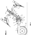
- the agricultural machine represented on the figure 1 is a plow (1).
- the plow (1) is intended to be connected to a tractor (2) by means of a coupling head (3).
- the plow (1) is connected in particular to the hitch (4) of the tractor (2). Only the rear part of the tractor (2) and its rear wheels (5) are visible on the figure 1 .
- the tractor (2) pulls the plow (1) in a direction of advance indicated by the arrow (A).
- the following notions "before”, “back” and “front”, “behind” are defined relative to the direction of advance (A).
- the plow (1) also has a frame (6), plow bodies (7), connecting pieces between the frame (6) and the plow bodies (7), safety devices whose role is to provide an impact with an obstacle to prevent the breakage of an essential part of the plow (1), and adjusting devices.
- the frame (6) generally carries a plurality of plow bodies (7) which are working pieces that cut, lift and turn the strip of soil.
- Each plow body (7) is rigidly connected to the frame (6) of the plow (1) via a respective age (8) and housing (9).
- the plow (1) represented in figure 1 is a mounted plow, it is connected to the tractor (2) by the three-point hitch controlled by the hydraulic lift of the tractor. It is reversible and is equipped with six plow bodies (7).
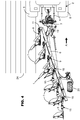
- the figure 2 shows in more detail, an age (8) mounted on the frame (6) with a respective housing (9).
- the age is connected to the frame (6) by a horizontal articulation (10) substantially horizontal axis and perpendicular to the work.
- the housing (9) is connected to frame (6) by a vertical articulation (11) with a substantially vertical axis at work.
- the age (8) comprises at its front end an axis of rotation (12) intended to bear against a bearing (13) formed in said housing (9).
- the axis of rotation (12) is substantially parallel to the axis of the horizontal articulation (10).
- a tie rod (14) holds the age (8) against the bearing (13) of the housing (9).
- the tie rod (14) is forced in tension by the action of a jack (15) which allows the plow body (7) to remain in the ground.
- Each age (8) is equipped with a non-stop hydraulic safety device allowing it to pivot upwards when the plow body (7) abuts against an obstacle formed by a rock.
- One end of the tie rod (14) is connected to the horizontal articulation (10) and the other end is connected to the ram (15) by another articulation (25).
- the cylinder (15) pulls the tie rod (14) to maintain the age (8) in a working position.
- the plow (1) comprises a device (16) for deliberately lifting an age (8) by pivoting about an axis corresponding substantially to said axis of rotation (12).
- said age (8) can be retracted intentionally or intentionally without changing the position of the frame (6) of the plow (1).
- the number of working bodies working the plow can be reduced voluntarily to adapt to the soil conditions.
- the user can reduce the number of plow bodies by raising the corresponding age.
- the last age (8) is equipped with the device (16) for lifting and holding it off the ground. It is retracted that is to say rotated anti-clockwise relative to the frame (6).
- the plow (1) works only with five bodies while it supports six.
- the last age (8) with the plow body (s) (7) that it carries can be kept out of the ground for plowing in difficult conditions. Thanks to the invention, the number of bodies can be modified according to ground conditions so that the total power absorbed by the working bodies can coincide or approach closer to the maximum power developed by the tractor.
- the figure 2 represents the last age (8) in its working position and the tie rod (14) substantially aligned with the frame (6) of the plow (1).
- the figure 3 represents the last age (8) in a rotated position, the plow bodies (7) are out of the ground.
- the tie rod (14) of age (8) has rotated relative to the frame (6) of the plow (1).
- the frame (6) remains substantially parallel to the ground surface.
- the raising of the age (8) is obtained by pushing said tie rod (14) on said housing (9). This thrust can rotate the age (8) upwardly about the axis of rotation (12).
- the device (16) for lifting the age (8) has, for this purpose, a double-acting cylinder.
- the jack (15) connected to the tie rod (14) is in the form of a double-acting jack. It is therefore the jack (15) double effect that pushes on the tie rod (14) to rotate the age (8) out of the ground.
- the large chamber of the cylinder (15) is supplied with oil for the purpose of raising the age (8) by pivoting and keep it off the ground.
- the device (16) for lifting the age (8), in particular the jack (15) with double effect, is controlled from the tractor cab (2).
- said device (16) also has a holding system (17) for maintaining the axis of rotation (12) against the bearing surface (13) of the housing (9). In this way, the guidance of the pivoting of the age (8) is ensured since the axis of rotation (12) can not be detached from the scope (13) of the housing (9).
- the holding system (17) has, for this purpose, a hook (18).
- the hook (18) extends substantially above the axis of rotation (12) and is capable of cooperating with a part of the periphery of the axis of rotation (12).
- the hook (18) cooperates with the upper half of the axis of rotation (12).
- the hook (18) is also configured to allow a lateral deflection of about 6 ° in the case where the body (7) meets a rock by the side.
- the holding system (17) is preferably connected to the housing (9).
- the pivoting of the age (8) is around an axis substantially corresponding to the axis of rotation (12).
- the plow (1) shown in the figures is reversible, so each age (8) carries a right plow body and a left plow body.
- the bodies are symmetrical with respect to a horizontal plane passing through the horizontal articulation (10).
- the frame (6) rotates 180 ° so that the plow bodies work alternately, it comprises a turning device (19).
- the plow (1) presents also a depth wheel (20). This wheel (20) is mounted at the rear of the frame (6) and ensures a control of the working depth in addition to the hitch (4) of the tractor (2).
- the front end of the age (8) has two axes of rotation (12).
- Each is intended to bear against a bearing (13) respectively formed in the housing (9).
- the upper axis of rotation extends above the lower axis of rotation, they are symmetrical with respect to the horizontal plane passing through the horizontal articulation (10).
- the jack (15) exerts a pull on the tie rod (14) so that the two axes of rotation remain in abutment against the bearing surfaces (13) of the casing (9).
- the axes of rotation (12) extend forward of the axis of the horizontal articulation (10).
- the cylinder (15) also makes it possible to achieve the non-stop hydraulic safety that is to say that the age (8) can be released by temporarily leaving the ground when the plow body (7) hits an obstacle then returns in the ground as soon as the obstacle is passed.
- the age safety trip range (8) is adjustable.
- the staves (13) are shown in broken lines on the figures 3 and 4 . These bearing surfaces (13) are semi-cylindrical and formed in the housing (9). According to an alternative not shown, the cylindrical surfaces (13) are made on the age and the axes of rotation (12) are formed on the housing (9). Alternatively, the spans (13) could be spherical.
- the tie rod (14) shown extends in age (8), it is a central tie rod. According to an alternative, the tie is placed outside the age.
- the holding system (17) comprises two hooks (18).
- the two hooks (18) are connected by a cylindrical axis (21). They are mounted on the housing (9).
- the holding system (17) has an upper hook and a lower hook. Said lower hook extends below and substantially vertically of said upper hook. The movement of said lower hook is combined with the movement of said upper hook through the cylindrical axis (21).
- the cylindrical axis (21) and the hooks (18) move in the housing (9).
- the holding system (17) is configured so that when the upper hook is active, the lower hook is inactive, and vice versa. It is therefore suitable for a reversible plow whose working bodies (7) work alternately.
- the activation of the holding system (17) is automatically based on the bodies that will work.
- the hook (18) adequate is set up by gravity.
- the activation of the holding system (17) and in particular the appropriate hook (18) is motorized.
- the upper hook is active when plowing on the right.
- the lower hook is active during plowing on the left.
- the distance separating the upper hook and the lower hook is constant and this distance is greater than the spacing between the upper axis of rotation and the lower axis of rotation of the age (8).
- the rear part of the hook (18) is not in contact with any part which allows the age (8) to move laterally in case of contact with a rock on the side of the plow body (7).
- the upper hook which holds the upper axis of rotation against the upper reach, the pivoting movement of the age (8) around the upper axis of rotation is guided during lifting as when lowering.
- the lower hook is inactive, the age (8) can pivot only around the upper axis of rotation when the cylinder (15) push.
- the figure 3 represents the last age (8) of the plow (1) that is raised.
- the large chamber (22) of the double-acting cylinder (15) was fed and the cylinder (15) extended to rotate the age (8) around the upper axis of rotation.
- the oil supply lines for the cylinders (15) are not shown in the figures.
- the upper hook is active, engaged on the upper axis of rotation, the lower axis of rotation has detached from the lower range of the housing (9) to allow pivoting.
- the plow bodies (7) extend above the ground surface and will not return the earth. So that the hook (18) remains active when the age (8) is raised, it is pressed against the axis of rotation (12) by a security (23).
- the security (23) extends over the age (8) and is achieved by an adjustable screw which bears against the upper part of the hook (18).
- the plow (1) of the figure 1 illustrates a solution with the last age (8) raised.
- the plow bodies (7) of this age (8) remain above the soil surface. It is also possible to equip the last two or three ages (8) of the plow (1) of a device (16) to raise the age. This allows you to momentarily use a six-body plow in very difficult conditions by reducing the number of bodies working only to four or three bodies.
- all the ages (8) of the plow (1) are equipped with a device (16) for lifting the age (8).
- Each age (8) can thus be lifted intentionally, this makes it possible to shorten the headlands during overturning at the end of the plot. Pounds are 5 to 10 meter strips where the tractor turns at the end of the plot. As soon as the plot is plowed, these pounds must be taken up by furrows perpendicular to the main furrows. These headlands generally have alternating triangular areas that are plowed and triangular areas that are not plowed.
- the earth inlet and the soil outlet of each age (8) are individually managed to minimize the width of the headlands.
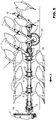
- the figure 4 represents a plow (1) in a line entry position with three bodies in work and three bodies that are still raised.
- the entry and the exit of line are made in a straight line (24) because all the bodies (7) return in earth and leave the ground, one after the other, as soon as they arrive at the level of the same perpendicular line to advancement.
- the grooves of the plow bodies (7) are shown schematically by lines that start with the straight line (24). With a straight pound band (without triangle), the number of crossing crossings is reduced and the finishes are much simpler.
- the figure 5 is a side view of the plow (1) shown on the figure 4 .
- the entry into the ground of the last three bodies is done as and when by the actuation of the cylinder (15) double effect of each age (8).
- the entries and exits of lines are thus shortened.
- the frame (6) remains substantially parallel to the ground surface.
- each age (8) on the frame (6) being known, it is possible to coordinate the entry or exit of each age (8) according to the forward speed of the tractor.
- the control of the different ages (8) of the plow (1) does not depend on the experience or the technicality of the user.
- the position of the different ages is automatically controlled according to their position and an imaginary line recorded in a GPS.
- the plow of the invention can be a simple plow and therefore not reversible.
- the holding device (17) has only a hook (18) whose position will be fixed on the axis of rotation (12).
- the plow of the invention may also be a semi-mounted plow or trailed.
Landscapes
- Life Sciences & Earth Sciences (AREA)
- Engineering & Computer Science (AREA)
- Mechanical Engineering (AREA)
- Soil Sciences (AREA)
- Environmental Sciences (AREA)
- Soil Working Implements (AREA)
- Lifting Devices For Agricultural Implements (AREA)
Priority Applications (1)
| Application Number | Priority Date | Filing Date | Title |
|---|---|---|---|
| PL11180032T PL2425696T3 (pl) | 2010-09-06 | 2011-09-05 | Pług z urządzeniem do podnoszenia co najmniej jednej grządzieli |
Applications Claiming Priority (1)
| Application Number | Priority Date | Filing Date | Title |
|---|---|---|---|
| FR1057037A FR2964292B1 (fr) | 2010-09-06 | 2010-09-06 | Charrue avec un dispositif pour soulever au moins un age |
Publications (2)
| Publication Number | Publication Date |
|---|---|
| EP2425696A1 EP2425696A1 (fr) | 2012-03-07 |
| EP2425696B1 true EP2425696B1 (fr) | 2018-04-04 |
Family
ID=43829788
Family Applications (1)
| Application Number | Title | Priority Date | Filing Date |
|---|---|---|---|
| EP11180032.2A Active EP2425696B1 (fr) | 2010-09-06 | 2011-09-05 | Charrue avec un dispositif pour soulever au moins un age |
Country Status (8)
| Country | Link |
|---|---|
| EP (1) | EP2425696B1 (pl) |
| DK (1) | DK2425696T3 (pl) |
| ES (1) | ES2670295T3 (pl) |
| FR (1) | FR2964292B1 (pl) |
| NO (1) | NO2425696T3 (pl) |
| PL (1) | PL2425696T3 (pl) |
| RU (1) | RU2566183C2 (pl) |
| UA (1) | UA109874C2 (pl) |
Families Citing this family (5)
| Publication number | Priority date | Publication date | Assignee | Title |
|---|---|---|---|---|
| DK178793B1 (en) * | 2015-07-08 | 2017-02-20 | Agro Intelligence Aps | A plough system and a method for ploughing |
| CN105519275B (zh) * | 2016-02-02 | 2017-05-24 | 河北省农林科学院棉花研究所 | 一种棉田土壤耕层重构及其配套栽培方法 |
| RU2631388C1 (ru) * | 2016-09-26 | 2017-09-21 | Федеральное государственное бюджетное образовательное учреждение высшего образования Горский государственный аграрный университет | Секция культиватора |
| US10806079B2 (en) | 2018-02-26 | 2020-10-20 | Deere & Company | Automatic product harvesting method and control system |
| CN119605357B (zh) * | 2024-12-14 | 2026-04-21 | 江苏常发农业装备股份有限公司 | 一种机具翻转控制方法和作业机 |
Citations (10)
| Publication number | Priority date | Publication date | Assignee | Title |
|---|---|---|---|---|
| US3561541A (en) | 1967-09-21 | 1971-02-09 | Roger W Woelfel | Tractor and implement hydraulic control system |
| FR2173784A1 (pl) | 1972-03-02 | 1973-10-12 | Thieme Gerard | |
| GB1483834A (en) | 1975-01-17 | 1977-08-24 | Ransomes Sims & Jefferies Ltd | Multi-furrow ploughs |
| FR2445099A1 (fr) | 1978-12-29 | 1980-07-25 | Fiskars Ab Oy | Organe de verrouillage pour un brabant double, equipe d'un mecanisme de degagement |
| EP0109882A1 (fr) | 1982-11-17 | 1984-05-30 | Société de Constructions Mécaniques HUARD-UCF Société Anonyme | Sécurité hydraulique pour charrues |
| WO1984002250A1 (en) | 1982-12-17 | 1984-06-21 | Sture Norelius | Device at a plough |
| GB2259839A (en) | 1991-09-24 | 1993-03-31 | Kverneland Klepp As | Plough body position control device |
| US5261495A (en) | 1991-01-11 | 1993-11-16 | Massey-Ferguson Services N.V. | Implement control |
| US5894894A (en) | 1996-05-15 | 1999-04-20 | Massey Ferguson S.A. | Control of a semi-mounted plough |
| US20080093093A1 (en) | 2006-10-24 | 2008-04-24 | Morris Industries Ltd | Combination Hydraulic Hold-Down and Lift System for an Agricultural Implement |
Family Cites Families (3)
| Publication number | Priority date | Publication date | Assignee | Title |
|---|---|---|---|---|
| NL8402323A (nl) * | 1984-07-23 | 1986-02-17 | Lely Nv C Van Der | Ploeg. |
| SU1588229A1 (ru) * | 1988-09-14 | 1992-06-30 | Ezhova V G | Лазер с солнечной накачкой |
| DE4117947A1 (de) * | 1991-05-31 | 1992-12-03 | Leipzig Bodenbearbeitung Veb | Hydromechanische ueberlastsicherung fuer beet- und drehpfluege |
-
2010
- 2010-09-06 FR FR1057037A patent/FR2964292B1/fr not_active Expired - Fee Related
-
2011
- 2011-09-05 ES ES11180032.2T patent/ES2670295T3/es active Active
- 2011-09-05 DK DK11180032.2T patent/DK2425696T3/en active
- 2011-09-05 EP EP11180032.2A patent/EP2425696B1/fr active Active
- 2011-09-05 PL PL11180032T patent/PL2425696T3/pl unknown
- 2011-09-05 NO NO11180032A patent/NO2425696T3/no unknown
- 2011-09-05 UA UAA201110707A patent/UA109874C2/ru unknown
- 2011-09-05 RU RU2011136840/13A patent/RU2566183C2/ru active
Patent Citations (10)
| Publication number | Priority date | Publication date | Assignee | Title |
|---|---|---|---|---|
| US3561541A (en) | 1967-09-21 | 1971-02-09 | Roger W Woelfel | Tractor and implement hydraulic control system |
| FR2173784A1 (pl) | 1972-03-02 | 1973-10-12 | Thieme Gerard | |
| GB1483834A (en) | 1975-01-17 | 1977-08-24 | Ransomes Sims & Jefferies Ltd | Multi-furrow ploughs |
| FR2445099A1 (fr) | 1978-12-29 | 1980-07-25 | Fiskars Ab Oy | Organe de verrouillage pour un brabant double, equipe d'un mecanisme de degagement |
| EP0109882A1 (fr) | 1982-11-17 | 1984-05-30 | Société de Constructions Mécaniques HUARD-UCF Société Anonyme | Sécurité hydraulique pour charrues |
| WO1984002250A1 (en) | 1982-12-17 | 1984-06-21 | Sture Norelius | Device at a plough |
| US5261495A (en) | 1991-01-11 | 1993-11-16 | Massey-Ferguson Services N.V. | Implement control |
| GB2259839A (en) | 1991-09-24 | 1993-03-31 | Kverneland Klepp As | Plough body position control device |
| US5894894A (en) | 1996-05-15 | 1999-04-20 | Massey Ferguson S.A. | Control of a semi-mounted plough |
| US20080093093A1 (en) | 2006-10-24 | 2008-04-24 | Morris Industries Ltd | Combination Hydraulic Hold-Down and Lift System for an Agricultural Implement |
Also Published As
| Publication number | Publication date |
|---|---|
| EP2425696A1 (fr) | 2012-03-07 |
| RU2566183C2 (ru) | 2015-10-20 |
| DK2425696T3 (en) | 2018-07-16 |
| NO2425696T3 (pl) | 2018-09-01 |
| RU2011136840A (ru) | 2013-03-10 |
| FR2964292B1 (fr) | 2013-09-27 |
| FR2964292A1 (fr) | 2012-03-09 |
| UA109874C2 (uk) | 2015-10-26 |
| PL2425696T3 (pl) | 2018-10-31 |
| ES2670295T3 (es) | 2018-05-29 |
Similar Documents
| Publication | Publication Date | Title |
|---|---|---|
| EP2425696B1 (fr) | Charrue avec un dispositif pour soulever au moins un age | |
| CA2226656C (fr) | Machine agricole de coupe perfectionnee | |
| EP3245857B1 (fr) | Machine agricole comportant un système de report de charge sécurisé | |
| FR2992143A1 (fr) | Dispositif d'accouplement perfectionne et machine agricole comportant un tel dispositif | |
| CA2857583C (fr) | Machine agricole avec un suivi de terrain ameliore pour les organes de travail | |
| FR2967546A1 (fr) | Semoir avec des elements d'appui decales | |
| EP2524583B1 (fr) | Charrue semi-portée monoroue à largeur de travail réglable | |
| EP2353351A1 (fr) | Charrue semi-portée réversible hors raie | |
| EP2534933A1 (fr) | Semoir avec des éléments de rappui constituant les roues de transport | |
| EP2629597B1 (fr) | Machine de recolte avec un dispositif d'allegement | |
| EP2923539A1 (fr) | Semoir avec un rouleau intégré pour détruire un couvert végétal | |
| EP2457424B1 (fr) | Charrue semi-portée avec un organe de nettoyage de roue perfectionné | |
| EP2282627B1 (fr) | Faucheuse avec un dispositif d'allègement perfectionné | |
| EP2534934B1 (fr) | Semoir avec un rouleau de rappui constitué de tronçons décalés | |
| EP2241170B1 (fr) | Chariot porteur pour charrue semi-portée | |
| EP1700517B1 (fr) | Charrue | |
| EP2314140A1 (fr) | Machine agricole pour le semis avec un moyen de rappui supplémentaire | |
| EP1466516B1 (fr) | Machine agricole comportant au moins une roue | |
| FR2901453A1 (fr) | Semoir semi-porte avec un cadre porteur et une articulation pivot | |
| EP3973756B1 (fr) | Machine agricole trainée de récolte avec un essieu réglable | |
| EP2708102A1 (fr) | Combinaison d'un instrument agricole et d'un appareil remorqué attelée à l'arrière d'un tracteur | |
| EP3048870A1 (fr) | Barre porte-outils avec un dispositif de verrouillage et machine agricole comportant une telle barre porte-outils | |
| EP2638792B1 (fr) | Semoir avec un réglage de la profondeur amélioré | |
| FR3135187A1 (fr) | Machine de fenaison sécurisée et protocole s’y rapportant | |
| WO1999055136A1 (fr) | Charrue multi-socs semi-portee avec bati articule |
Legal Events
| Date | Code | Title | Description |
|---|---|---|---|
| AK | Designated contracting states |
Kind code of ref document: A1 Designated state(s): AL AT BE BG CH CY CZ DE DK EE ES FI FR GB GR HR HU IE IS IT LI LT LU LV MC MK MT NL NO PL PT RO RS SE SI SK SM TR |
|
| AX | Request for extension of the european patent |
Extension state: BA ME |
|
| PUAI | Public reference made under article 153(3) epc to a published international application that has entered the european phase |
Free format text: ORIGINAL CODE: 0009012 |
|
| 17P | Request for examination filed |
Effective date: 20120907 |
|
| STAA | Information on the status of an ep patent application or granted ep patent |
Free format text: STATUS: EXAMINATION IS IN PROGRESS |
|
| 17Q | First examination report despatched |
Effective date: 20170316 |
|
| GRAP | Despatch of communication of intention to grant a patent |
Free format text: ORIGINAL CODE: EPIDOSNIGR1 |
|
| STAA | Information on the status of an ep patent application or granted ep patent |
Free format text: STATUS: GRANT OF PATENT IS INTENDED |
|
| INTG | Intention to grant announced |
Effective date: 20171024 |
|
| GRAS | Grant fee paid |
Free format text: ORIGINAL CODE: EPIDOSNIGR3 |
|
| GRAA | (expected) grant |
Free format text: ORIGINAL CODE: 0009210 |
|
| STAA | Information on the status of an ep patent application or granted ep patent |
Free format text: STATUS: THE PATENT HAS BEEN GRANTED |
|
| AK | Designated contracting states |
Kind code of ref document: B1 Designated state(s): AL AT BE BG CH CY CZ DE DK EE ES FI FR GB GR HR HU IE IS IT LI LT LU LV MC MK MT NL NO PL PT RO RS SE SI SK SM TR |
|
| REG | Reference to a national code |
Ref country code: GB Ref legal event code: FG4D Free format text: NOT ENGLISH |
|
| REG | Reference to a national code |
Ref country code: CH Ref legal event code: EP |
|
| REG | Reference to a national code |
Ref country code: AT Ref legal event code: REF Ref document number: 984544 Country of ref document: AT Kind code of ref document: T Effective date: 20180415 |
|
| REG | Reference to a national code |
Ref country code: IE Ref legal event code: FG4D Free format text: LANGUAGE OF EP DOCUMENT: FRENCH |
|
| REG | Reference to a national code |
Ref country code: DE Ref legal event code: R096 Ref document number: 602011047075 Country of ref document: DE |
|
| REG | Reference to a national code |
Ref country code: ES Ref legal event code: FG2A Ref document number: 2670295 Country of ref document: ES Kind code of ref document: T3 Effective date: 20180529 |
|
| REG | Reference to a national code |
Ref country code: NL Ref legal event code: FP |
|
| REG | Reference to a national code |
Ref country code: DK Ref legal event code: T3 Effective date: 20180711 |
|
| REG | Reference to a national code |
Ref country code: NO Ref legal event code: T2 Effective date: 20180404 |
|
| REG | Reference to a national code |
Ref country code: LT Ref legal event code: MG4D |
|
| REG | Reference to a national code |
Ref country code: FR Ref legal event code: PLFP Year of fee payment: 8 |
|
| PG25 | Lapsed in a contracting state [announced via postgrant information from national office to epo] |
Ref country code: FI Free format text: LAPSE BECAUSE OF FAILURE TO SUBMIT A TRANSLATION OF THE DESCRIPTION OR TO PAY THE FEE WITHIN THE PRESCRIBED TIME-LIMIT Effective date: 20180404 Ref country code: LT Free format text: LAPSE BECAUSE OF FAILURE TO SUBMIT A TRANSLATION OF THE DESCRIPTION OR TO PAY THE FEE WITHIN THE PRESCRIBED TIME-LIMIT Effective date: 20180404 Ref country code: BG Free format text: LAPSE BECAUSE OF FAILURE TO SUBMIT A TRANSLATION OF THE DESCRIPTION OR TO PAY THE FEE WITHIN THE PRESCRIBED TIME-LIMIT Effective date: 20180704 Ref country code: SE Free format text: LAPSE BECAUSE OF FAILURE TO SUBMIT A TRANSLATION OF THE DESCRIPTION OR TO PAY THE FEE WITHIN THE PRESCRIBED TIME-LIMIT Effective date: 20180404 Ref country code: AL Free format text: LAPSE BECAUSE OF FAILURE TO SUBMIT A TRANSLATION OF THE DESCRIPTION OR TO PAY THE FEE WITHIN THE PRESCRIBED TIME-LIMIT Effective date: 20180404 |
|
| PG25 | Lapsed in a contracting state [announced via postgrant information from national office to epo] |
Ref country code: RS Free format text: LAPSE BECAUSE OF FAILURE TO SUBMIT A TRANSLATION OF THE DESCRIPTION OR TO PAY THE FEE WITHIN THE PRESCRIBED TIME-LIMIT Effective date: 20180404 Ref country code: GR Free format text: LAPSE BECAUSE OF FAILURE TO SUBMIT A TRANSLATION OF THE DESCRIPTION OR TO PAY THE FEE WITHIN THE PRESCRIBED TIME-LIMIT Effective date: 20180705 Ref country code: HR Free format text: LAPSE BECAUSE OF FAILURE TO SUBMIT A TRANSLATION OF THE DESCRIPTION OR TO PAY THE FEE WITHIN THE PRESCRIBED TIME-LIMIT Effective date: 20180404 Ref country code: LV Free format text: LAPSE BECAUSE OF FAILURE TO SUBMIT A TRANSLATION OF THE DESCRIPTION OR TO PAY THE FEE WITHIN THE PRESCRIBED TIME-LIMIT Effective date: 20180404 |
|
| REG | Reference to a national code |
Ref country code: DE Ref legal event code: R026 Ref document number: 602011047075 Country of ref document: DE |
|
| PLBI | Opposition filed |
Free format text: ORIGINAL CODE: 0009260 |
|
| PG25 | Lapsed in a contracting state [announced via postgrant information from national office to epo] |
Ref country code: PT Free format text: LAPSE BECAUSE OF FAILURE TO SUBMIT A TRANSLATION OF THE DESCRIPTION OR TO PAY THE FEE WITHIN THE PRESCRIBED TIME-LIMIT Effective date: 20180806 |
|
| 26 | Opposition filed |
Opponent name: CNH INDUSTRIAL BELGIUM NV Effective date: 20181207 |
|
| PLAX | Notice of opposition and request to file observation + time limit sent |
Free format text: ORIGINAL CODE: EPIDOSNOBS2 |
|
| PG25 | Lapsed in a contracting state [announced via postgrant information from national office to epo] |
Ref country code: EE Free format text: LAPSE BECAUSE OF FAILURE TO SUBMIT A TRANSLATION OF THE DESCRIPTION OR TO PAY THE FEE WITHIN THE PRESCRIBED TIME-LIMIT Effective date: 20180404 Ref country code: CZ Free format text: LAPSE BECAUSE OF FAILURE TO SUBMIT A TRANSLATION OF THE DESCRIPTION OR TO PAY THE FEE WITHIN THE PRESCRIBED TIME-LIMIT Effective date: 20180404 Ref country code: SK Free format text: LAPSE BECAUSE OF FAILURE TO SUBMIT A TRANSLATION OF THE DESCRIPTION OR TO PAY THE FEE WITHIN THE PRESCRIBED TIME-LIMIT Effective date: 20180404 Ref country code: RO Free format text: LAPSE BECAUSE OF FAILURE TO SUBMIT A TRANSLATION OF THE DESCRIPTION OR TO PAY THE FEE WITHIN THE PRESCRIBED TIME-LIMIT Effective date: 20180404 |
|
| PG25 | Lapsed in a contracting state [announced via postgrant information from national office to epo] |
Ref country code: SM Free format text: LAPSE BECAUSE OF FAILURE TO SUBMIT A TRANSLATION OF THE DESCRIPTION OR TO PAY THE FEE WITHIN THE PRESCRIBED TIME-LIMIT Effective date: 20180404 |
|
| PG25 | Lapsed in a contracting state [announced via postgrant information from national office to epo] |
Ref country code: MC Free format text: LAPSE BECAUSE OF FAILURE TO SUBMIT A TRANSLATION OF THE DESCRIPTION OR TO PAY THE FEE WITHIN THE PRESCRIBED TIME-LIMIT Effective date: 20180404 |
|
| PLBP | Opposition withdrawn |
Free format text: ORIGINAL CODE: 0009264 |
|
| PG25 | Lapsed in a contracting state [announced via postgrant information from national office to epo] |
Ref country code: SI Free format text: LAPSE BECAUSE OF FAILURE TO SUBMIT A TRANSLATION OF THE DESCRIPTION OR TO PAY THE FEE WITHIN THE PRESCRIBED TIME-LIMIT Effective date: 20180404 |
|
| REG | Reference to a national code |
Ref country code: BE Ref legal event code: MM Effective date: 20180930 |
|
| REG | Reference to a national code |
Ref country code: IE Ref legal event code: MM4A |
|
| PG25 | Lapsed in a contracting state [announced via postgrant information from national office to epo] |
Ref country code: LU Free format text: LAPSE BECAUSE OF NON-PAYMENT OF DUE FEES Effective date: 20180905 |
|
| PLBD | Termination of opposition procedure: decision despatched |
Free format text: ORIGINAL CODE: EPIDOSNOPC1 |
|
| PG25 | Lapsed in a contracting state [announced via postgrant information from national office to epo] |
Ref country code: IE Free format text: LAPSE BECAUSE OF NON-PAYMENT OF DUE FEES Effective date: 20180905 |
|
| REG | Reference to a national code |
Ref country code: DE Ref legal event code: R100 Ref document number: 602011047075 Country of ref document: DE |
|
| PG25 | Lapsed in a contracting state [announced via postgrant information from national office to epo] |
Ref country code: BE Free format text: LAPSE BECAUSE OF NON-PAYMENT OF DUE FEES Effective date: 20180930 |
|
| PLBM | Termination of opposition procedure: date of legal effect published |
Free format text: ORIGINAL CODE: 0009276 |
|
| 27C | Opposition proceedings terminated |
Effective date: 20190808 |
|
| PG25 | Lapsed in a contracting state [announced via postgrant information from national office to epo] |
Ref country code: MT Free format text: LAPSE BECAUSE OF FAILURE TO SUBMIT A TRANSLATION OF THE DESCRIPTION OR TO PAY THE FEE WITHIN THE PRESCRIBED TIME-LIMIT Effective date: 20180404 |
|
| PG25 | Lapsed in a contracting state [announced via postgrant information from national office to epo] |
Ref country code: TR Free format text: LAPSE BECAUSE OF FAILURE TO SUBMIT A TRANSLATION OF THE DESCRIPTION OR TO PAY THE FEE WITHIN THE PRESCRIBED TIME-LIMIT Effective date: 20180404 |
|
| PG25 | Lapsed in a contracting state [announced via postgrant information from national office to epo] |
Ref country code: HU Free format text: LAPSE BECAUSE OF FAILURE TO SUBMIT A TRANSLATION OF THE DESCRIPTION OR TO PAY THE FEE WITHIN THE PRESCRIBED TIME-LIMIT; INVALID AB INITIO Effective date: 20110905 |
|
| PG25 | Lapsed in a contracting state [announced via postgrant information from national office to epo] |
Ref country code: MK Free format text: LAPSE BECAUSE OF NON-PAYMENT OF DUE FEES Effective date: 20180404 Ref country code: CY Free format text: LAPSE BECAUSE OF FAILURE TO SUBMIT A TRANSLATION OF THE DESCRIPTION OR TO PAY THE FEE WITHIN THE PRESCRIBED TIME-LIMIT Effective date: 20180404 |
|
| PG25 | Lapsed in a contracting state [announced via postgrant information from national office to epo] |
Ref country code: IS Free format text: LAPSE BECAUSE OF FAILURE TO SUBMIT A TRANSLATION OF THE DESCRIPTION OR TO PAY THE FEE WITHIN THE PRESCRIBED TIME-LIMIT Effective date: 20180804 |
|
| REG | Reference to a national code |
Ref country code: AT Ref legal event code: UEP Ref document number: 984544 Country of ref document: AT Kind code of ref document: T Effective date: 20180404 |
|
| REG | Reference to a national code |
Ref country code: CH Ref legal event code: U11 Free format text: ST27 STATUS EVENT CODE: U-0-0-U10-U11 (AS PROVIDED BY THE NATIONAL OFFICE) Effective date: 20251001 |
|
| PGFP | Annual fee paid to national office [announced via postgrant information from national office to epo] |
Ref country code: DK Payment date: 20250925 Year of fee payment: 15 Ref country code: DE Payment date: 20250929 Year of fee payment: 15 |
|
| PGFP | Annual fee paid to national office [announced via postgrant information from national office to epo] |
Ref country code: NO Payment date: 20250929 Year of fee payment: 15 |
|
| PGFP | Annual fee paid to national office [announced via postgrant information from national office to epo] |
Ref country code: NL Payment date: 20250926 Year of fee payment: 15 Ref country code: PL Payment date: 20250819 Year of fee payment: 15 Ref country code: IT Payment date: 20250919 Year of fee payment: 15 |
|
| PGFP | Annual fee paid to national office [announced via postgrant information from national office to epo] |
Ref country code: GB Payment date: 20250929 Year of fee payment: 15 |
|
| PGFP | Annual fee paid to national office [announced via postgrant information from national office to epo] |
Ref country code: FR Payment date: 20250925 Year of fee payment: 15 Ref country code: AT Payment date: 20250929 Year of fee payment: 15 |
|
| PGFP | Annual fee paid to national office [announced via postgrant information from national office to epo] |
Ref country code: CH Payment date: 20251001 Year of fee payment: 15 |
|
| PGFP | Annual fee paid to national office [announced via postgrant information from national office to epo] |
Ref country code: ES Payment date: 20251001 Year of fee payment: 15 |