EP2425694B1 - Noeud de réseau de communications - Google Patents
Noeud de réseau de communications Download PDFInfo
- Publication number
- EP2425694B1 EP2425694B1 EP09776568.9A EP09776568A EP2425694B1 EP 2425694 B1 EP2425694 B1 EP 2425694B1 EP 09776568 A EP09776568 A EP 09776568A EP 2425694 B1 EP2425694 B1 EP 2425694B1
- Authority
- EP
- European Patent Office
- Prior art keywords
- node
- equipment
- region
- pathway
- heat exchanger
- Prior art date
- Legal status (The legal status is an assumption and is not a legal conclusion. Google has not performed a legal analysis and makes no representation as to the accuracy of the status listed.)
- Active
Links
Images
Classifications
-
- H—ELECTRICITY
- H05—ELECTRIC TECHNIQUES NOT OTHERWISE PROVIDED FOR
- H05K—PRINTED CIRCUITS; CASINGS OR CONSTRUCTIONAL DETAILS OF ELECTRIC APPARATUS; MANUFACTURE OF ASSEMBLAGES OF ELECTRICAL COMPONENTS
- H05K7/00—Constructional details common to different types of electric apparatus
- H05K7/20—Modifications to facilitate cooling, ventilating, or heating
- H05K7/20536—Modifications to facilitate cooling, ventilating, or heating for racks or cabinets of standardised dimensions, e.g. electronic racks for aircraft or telecommunication equipment
- H05K7/206—Air circulating in closed loop within cabinets wherein heat is removed through air-to-air heat-exchanger
Definitions
- the present invention relates generally to communications network nodes.
- thermoelectric generator preferably comprises a plurality of thermocouple devices connected in serial and parallel arrangement.
- the node is arranged to supply electricity from the thermoelectric generator to the equipment.
- the heat exchanger may be located above a region arranged to receive the equipment.
- the node may comprise a divider structure which substantially thermally isolates the inlet region from the outlet region.
- the divider structure is preferably arranged to receive the equipment such that an inlet portion of the equipment is located in communication with the inlet region and an outlet portion of the equipment is located in communication with the outlet region.
- the node is preferably arranged to guide fluid upwardly into the outlet region.
- the node most preferably comprises a guide surface to guide the fluid upwardly into the fluid outlet region.
- a cold side of the heat exchanger is desirably in thermal communication with an external surface of the node.
- the node may desirably be suitable for location in an outdoor environment.
- the node preferably comprises a street side cabinet.
- the node preferably comprises a housing arranged to enclose the communications network node equipment, which equipment arranged to provide communication between communication network links.
- the housing preferably encloses the pathway and the heat exchanger.
- the pathway may extend away from the housing, with the heat exchanger located remotely from the housing.
- a communications network node comprising a housing apparatus 1 enclosing network node equipment 10 and heat exchange apparatus.
- the housing apparatus 1 is of the type generally known as a street side cabinet, a dog-house or a manhole and is suitable for location in an outdoor environment.
- the network node equipment 10 serves to provide a bridge between an optical fibre 30, which is connected to a regional or local exchange, and metallic cabling 41, 42 and 43, which are connected to respective user premises.
- the network node equipment 10 may comprise telecommunications network equipment such as a switch, Internet Protocol Digital Subscriber Line Access Multiplexer (IPDSLAM), or an Optical Network Unit (ONU), for example.
- IPDSLAM Internet Protocol Digital Subscriber Line Access Multiplexer
- ONU Optical Network Unit
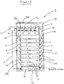
- the node comprises an inlet region 3 for coolant air to flow towards the equipment 10 and an outlet region for coolant air to flow away from the equipment, and the apparatus further comprises a pathway comprising pathway portions 7a and 7b, defined by respective conduit structures 27a and 27b to connect the inlet region 3 to the outlet region 5.
- the node further comprises a heat exchange arrangement 9 which is in thermal communication with the pathway. Coolant air is circulated through the equipment and the pathway in order to ensure that the equipment does not overheat.
- the equipment 10 comprises a plurality of equipment units which, as shown in Figure 1 , are arranged in a rack assembly with the units arranged one above the other.
- One end of 10a of each of the equipment units is arranged to receive air from the inlet region 3. Adjacent to the respective ends 10a there are provided guide surfaces 14 which save to deflect air towards said respective ends 10a.
- the air On entering the equipment 10, the air receives heat produced by the equipment and the heat air is conveyed towards respective opposite ends 10b of the equipment units.
- the heated air exits the equipment units at the ends 10b and enters into the outlet region 5.
- guide surfaces 15 deflect the output heated air upwards, thereby assisting the conveyance of the air towards the pathway.
- the heated air rises from the outlet region towards an uppermost part of the pathway. Conveyance of the air towards the uppermost part of the pathway is assisted by a fan assembly 19b which urges the heated air upwards.
- the air On reaching the uppermost part of the pathway the air is drawn through the heat exchange arrangement 9.
- the heat exchange arrangement 9 comprises a plurality of thermoelectric generators 20.
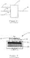
- One such generator is shown in Figure 3 .
- the generator 20 comprises a hot side 21 and a cold side substrate 22.
- the hot side substrate and the cold side substrate 22 sandwich an array 23 of p-pellets and n-pellets to form a thermocouple device.
- the hot side substrate is in thermal communication with the environment external of the apparatus.
- the cold side substrate is connected to cooling fin structure 22a.
- the temperature gradient between the hot side substrate 21 and the cold side substrate 22 produces electrical power derived from the movement of electrical carriers through thermoelectric pellets brought on by a heat flow. Heat is effectively exchanged for electrical power.
- thermoelectric pellets brought on by a heat flow. Heat is effectively exchanged for electrical power.
- positive charge in one of the p-pellets and electrons in an adjacent n-pellet move towards the heat sink producing a small voltage. Since the p-pellets and the n-pellets are connected in series the total voltage produced by the generator is in the sum of the voltages.
- the voltage is fed to a DC/DC converter 17, which in turn, is connected to the power supply unit 16 of the apparatus 1.
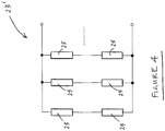
- serial connection of n-pellets and p-pellets is shown, pairs of the pellets may be arranged in parallel formation, or in a serial/parallel arrangement.
- Such a hybrid serial/parallel arrangement 23' is shown in Figure 4 , with respective pairs of n-pellets and p-pellets shown schematically as circuit elements 25 and multiple elements 25 connected in series on each parallel branch.
- respective pairs of n-pellets and p-pellets shown schematically as circuit elements 25 and multiple elements 25 connected in series on each parallel branch.
- the region 3 and the outlet region 5 are substantially thermally isolated from one another by virtue of a divider wall structure 13. This ensures that there is substantially no conduction of heat between air at the inlet region 3 and air at the outlet region 5.
- a divider wall structure 13 As can be seen from Figure 1 , suitably dimensioned vertically-spaced apertures 13a are conveniently provided in the divider structure 13 to allow racking of the equipment units 10 and the power supply unit 16.
- Outer casing 30 of the housing apparatus 1 is advantageously sealed such that ingress of air from the exterior environment is substantially prevented into the internal volume of the apparatus, or at least into the pathway.
- this will result in reduced maintenance time required to service the housing apparatus 1 in respect of replacing or renewing fan components, such as dust filters, in view of dust accumulation which brings about energy inefficiencies in powering the fans.
- the same advantages of reduced maintenance apply in respect of the fans 19a and 19b.
- the external power required to be supplied to the apparatus is reduced. This would otherwise have been energy which would simply have been dissipated into the exterior environment.
- a further important advantage is that by converting the produced heat to electrical energy, the quantity of heat inside the apparatus is reduced. This, in turn means that the energy required to achieve sufficient cooling is reduced.
- Coolant air follows a substantially horizontal path through the equipment units 10 stemming from the fact that the housing apparatus 1 is fixed in a substantially upright position.
- the housing apparatus 1 is arranged in a tilted condition such that the inlet ends 10a of the equipment units 10 are higher than the outlet ends 10b.
- the housing could be inclined at an angle of around 20° to 30° relative to the vertical.
- the housing 1 could remain upright whereas the rack assembly is arranged to hold the equipment units 10 at a suitable angular attitude.
- the angular inclination of the passage of air through the units acts to increase the flow of air therethrough which reduces the energy required for cooling.
- additional cooling of the air could be achieved by using the electrical power derived from output heat to power a Peltier cooler device.
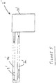
- a pathway 7a', 7b' extends remotely from an exterior casing 30' of the apparatus which encloses telecommunication units to a heat exchange arrangement 9' which is also remotely located.
- the heat exchange arrangement 9' could be located at domestic or commercial premises and could be arranged to transfer heat from the coolant air to heat water (or another fluid) for example for use in providing heating to the premises.
- coolant conduits of multiple housing apparatus which are in proximity to each other, are connected to a common or shared heat exchanger.
- liquid such as water
- water would be used as the coolant fluid.
Landscapes
- Engineering & Computer Science (AREA)
- Aviation & Aerospace Engineering (AREA)
- Physics & Mathematics (AREA)
- Thermal Sciences (AREA)
- Microelectronics & Electronic Packaging (AREA)
- Cooling Or The Like Of Electrical Apparatus (AREA)
Claims (13)
- Noeud de réseau de communication comprenant un équipement de communication (10) ; le noeud comprenant en outre, une région d'entrée (3) pour qu'un liquide de refroidissement s'écoule vers l'équipement et une région de sortie (5) pour que le liquide de refroidissement s'écoule loin de l'équipement, un chemin (7a, 7b) allant de la région de sortie à la région d'entrée, le chemin formant une partie d'un circuit fermé pour le liquide de refroidissement, un échangeur de chaleur (9) en communication thermique avec le chemin,
et caractérisé par
un générateur thermoélectrique (20) compris dans l'échangeur de chaleur (9), le générateur thermoélectrique étant agencé pour produire de l'électricité à partir du liquide de refroidissement chauffé et pour fournir l'électricité à l'équipement de communication. - Noeud selon la revendication 1, dans laquelle le générateur thermoélectrique comprend une pluralité de dispositifs à thermocouple (20) reliés dans un agencement série et parallèle.
- Noeud selon l'une quelconque des revendications précédentes, dans lequel l'échangeur de chaleur (9) est situé au-dessus d'une région agencée pour recevoir l'équipement (10).
- Noeud selon l'une quelconque des revendications précédentes, qui comprend une structure de séparateur (13) qui isole sensiblement de façon thermique la région d'entrée (3) de la région de sortie (5).
- Noeud selon la revendication 4, la structure de séparateur (13) étant agencée pour recevoir l'équipement (10) de sorte qu'une portion d'entrée (10a) de l'équipement est située en communication avec la région d'entrée (3) et une portion de sortie de l'équipement est située en communication avec la région de sortie (5).
- Noeud selon l'une quelconque des revendications précédentes, agencé pour guider du fluide vers le haut dans la région de sortie (5).
- Noeud selon la revendication 6, qui comprend une surface de guidage (15) pour guider le fluide vers le haut dans la région de sortie de fluide (5).
- Noeud selon l'une quelconque des revendications précédentes, dans lequel un côté froid (22) de l'échangeur de chaleur (9) est en communication thermique avec une surface externe du noeud.
- Noeud selon l'une quelconque des revendications précédentes, agencé pour être approprié pour une localisation dans un environnement extérieur.
- Noeud selon l'une quelconque des revendications précédentes, qui comprend un coffret côté rue.
- Noeud selon l'une quelconque des revendications précédentes, qui comprend un logement (1) agencé pour englober l'équipement de communication (10), lequel équipement est agencé pour fournir une communication entre des liaisons de réseau de communication (30, 41, 42, 43).
- Noeud selon la revendication 11, dans lequel le logement (1) englobe le chemin (7a, 7b) et l'échangeur de chaleur (9).
- Noeud selon la revendication 12, dans lequel le chemin s'étend loin du logement (1) et de l'échangeur de chaleur (9) situé à distance du logement.
Applications Claiming Priority (1)
| Application Number | Priority Date | Filing Date | Title |
|---|---|---|---|
| PCT/EP2009/003083 WO2010124700A1 (fr) | 2009-04-28 | 2009-04-28 | Noeud de réseau de communications |
Publications (2)
| Publication Number | Publication Date |
|---|---|
| EP2425694A1 EP2425694A1 (fr) | 2012-03-07 |
| EP2425694B1 true EP2425694B1 (fr) | 2017-11-01 |
Family
ID=41396148
Family Applications (1)
| Application Number | Title | Priority Date | Filing Date |
|---|---|---|---|
| EP09776568.9A Active EP2425694B1 (fr) | 2009-04-28 | 2009-04-28 | Noeud de réseau de communications |
Country Status (3)
| Country | Link |
|---|---|
| US (1) | US20120006505A1 (fr) |
| EP (1) | EP2425694B1 (fr) |
| WO (1) | WO2010124700A1 (fr) |
Families Citing this family (6)
| Publication number | Priority date | Publication date | Assignee | Title |
|---|---|---|---|---|
| US9781865B2 (en) * | 2008-05-02 | 2017-10-03 | Jason Todd Roth | System and method of cooling and ventilating for an electronics cabinet |
| WO2012075624A1 (fr) * | 2010-12-07 | 2012-06-14 | 北京纳源丰科技发展有限公司 | Armoire frigorifique intégrée |
| US9076893B2 (en) * | 2011-05-20 | 2015-07-07 | At&T Intellectual Property I, L.P. | Task-lit cabinet |
| DE102014007901A1 (de) * | 2014-05-27 | 2015-12-03 | Friedrich Lütze GmbH | Klimatisierungsanordnung |
| US9832912B2 (en) * | 2015-05-07 | 2017-11-28 | Dhk Storage, Llc | Computer server heat regulation utilizing integrated precision air flow |
| CN105425353A (zh) * | 2016-01-18 | 2016-03-23 | 哈尔滨理工大学 | 一种通信工程光纤交换箱 |
Family Cites Families (10)
| Publication number | Priority date | Publication date | Assignee | Title |
|---|---|---|---|---|
| GB2284659A (en) * | 1993-11-22 | 1995-06-14 | Malcoe Precision Fabrications | Electrical apparatus enclosure with cooling air circulated in a closed path |
| US6058712A (en) * | 1996-07-12 | 2000-05-09 | Thermotek, Inc. | Hybrid air conditioning system and a method therefor |
| US6538883B1 (en) * | 2001-09-19 | 2003-03-25 | Turin Networks | Method and apparatus for thermally insulated and earth cooled electronic components within an electronic system |
| US6877551B2 (en) * | 2002-07-11 | 2005-04-12 | Avaya Technology Corp. | Systems and methods for weatherproof cabinets with variably cooled compartments |
| US6854275B2 (en) * | 2002-08-08 | 2005-02-15 | International Business Machines Corporation | Method for cooling automated storage library media using thermoelectric cooler |
| DE202004006552U1 (de) * | 2004-04-26 | 2004-07-08 | Knürr AG | Kühlungssystem für Geräte- und Netzwerkschränke |
| US7683270B2 (en) * | 2005-06-03 | 2010-03-23 | Telect Inc. | Telecommunications cabinet |
| JP2007179655A (ja) * | 2005-12-28 | 2007-07-12 | Hitachi Ltd | ディスクアレイ装置 |
| US20080178920A1 (en) * | 2006-12-28 | 2008-07-31 | Schlumberger Technology Corporation | Devices for cooling and power |
| US7974094B2 (en) * | 2007-03-27 | 2011-07-05 | Commscope, Inc. Of North Carolina | Outside plant telecommunications cabinet direct air cooling system |
-
2009
- 2009-04-28 EP EP09776568.9A patent/EP2425694B1/fr active Active
- 2009-04-28 WO PCT/EP2009/003083 patent/WO2010124700A1/fr not_active Ceased
- 2009-04-28 US US13/255,947 patent/US20120006505A1/en not_active Abandoned
Non-Patent Citations (1)
| Title |
|---|
| None * |
Also Published As
| Publication number | Publication date |
|---|---|
| EP2425694A1 (fr) | 2012-03-07 |
| WO2010124700A1 (fr) | 2010-11-04 |
| US20120006505A1 (en) | 2012-01-12 |
Similar Documents
| Publication | Publication Date | Title |
|---|---|---|
| EP2425694B1 (fr) | Noeud de réseau de communications | |
| KR101291440B1 (ko) | 태양광 인버터 캐비닛 구조 | |
| US8089766B2 (en) | Server case with optical input/output and/or wireless power supply | |
| CN209358435U (zh) | 一种紧凑型svg功率单元 | |
| CN110072368A (zh) | 被冷却的电子系统 | |
| CN109792228B (zh) | 具有集成电路的用于发电的系统和设备 | |
| JP2022002466A (ja) | 太陽電池接続箱のための熱放散 | |
| EP4285696A1 (fr) | Module de centre de données hybride | |
| WO2024239584A1 (fr) | Convertisseur de puissance ayant une unité de dissipation de chaleur composite air-liquide, et système de stockage d'énergie | |
| CN208368494U (zh) | 模块化多电平换流器半桥功率单元 | |
| CN217589923U (zh) | 一种户外模块化储能变流器集成系统 | |
| CN104756616B (zh) | 太阳能逆变器 | |
| JP5903645B2 (ja) | 蓄電池管理システム | |
| CN211792649U (zh) | 一种泛在物联网用散热型通信设备 | |
| CN219937737U (zh) | 一种电气柜体单元、电气柜体组合及电气柜体工作组 | |
| CN217936316U (zh) | 一种大型风电机组变流器冷却装置 | |
| CN206559215U (zh) | 一种用于级联式高压大功率变流器的结构装置 | |
| WO2020199264A1 (fr) | Chauffe-eau électrique et procédé de commande associé | |
| CN201594785U (zh) | 拉出电阻 | |
| WO2014155411A1 (fr) | Support de logement d'accumulateurs électriques | |
| CN113660836A (zh) | 一种变流器内部散热系统 | |
| KR20190063935A (ko) | 국선과 구내선의 접속장치 | |
| CN210042473U (zh) | 电器柜及变流器 | |
| CN208337213U (zh) | 液冷式充电机、充电机群以及充电机群集中式液冷系统 | |
| CN207994911U (zh) | 变流器并网柜 |
Legal Events
| Date | Code | Title | Description |
|---|---|---|---|
| PUAI | Public reference made under article 153(3) epc to a published international application that has entered the european phase |
Free format text: ORIGINAL CODE: 0009012 |
|
| 17P | Request for examination filed |
Effective date: 20111124 |
|
| AK | Designated contracting states |
Kind code of ref document: A1 Designated state(s): AT BE BG CH CY CZ DE DK EE ES FI FR GB GR HR HU IE IS IT LI LT LU LV MC MK MT NL NO PL PT RO SE SI SK TR |
|
| DAX | Request for extension of the european patent (deleted) | ||
| GRAP | Despatch of communication of intention to grant a patent |
Free format text: ORIGINAL CODE: EPIDOSNIGR1 |
|
| INTG | Intention to grant announced |
Effective date: 20170728 |
|
| GRAS | Grant fee paid |
Free format text: ORIGINAL CODE: EPIDOSNIGR3 |
|
| GRAA | (expected) grant |
Free format text: ORIGINAL CODE: 0009210 |
|
| AK | Designated contracting states |
Kind code of ref document: B1 Designated state(s): AT BE BG CH CY CZ DE DK EE ES FI FR GB GR HR HU IE IS IT LI LT LU LV MC MK MT NL NO PL PT RO SE SI SK TR |
|
| REG | Reference to a national code |
Ref country code: GB Ref legal event code: FG4D |
|
| REG | Reference to a national code |
Ref country code: CH Ref legal event code: EP Ref country code: AT Ref legal event code: REF Ref document number: 943245 Country of ref document: AT Kind code of ref document: T Effective date: 20171115 |
|
| REG | Reference to a national code |
Ref country code: IE Ref legal event code: FG4D |
|
| REG | Reference to a national code |
Ref country code: DE Ref legal event code: R096 Ref document number: 602009049150 Country of ref document: DE |
|
| REG | Reference to a national code |
Ref country code: NL Ref legal event code: MP Effective date: 20171101 |
|
| REG | Reference to a national code |
Ref country code: LT Ref legal event code: MG4D |
|
| REG | Reference to a national code |
Ref country code: AT Ref legal event code: MK05 Ref document number: 943245 Country of ref document: AT Kind code of ref document: T Effective date: 20171101 |
|
| REG | Reference to a national code |
Ref country code: FR Ref legal event code: PLFP Year of fee payment: 10 |
|
| PG25 | Lapsed in a contracting state [announced via postgrant information from national office to epo] |
Ref country code: SE Free format text: LAPSE BECAUSE OF FAILURE TO SUBMIT A TRANSLATION OF THE DESCRIPTION OR TO PAY THE FEE WITHIN THE PRESCRIBED TIME-LIMIT Effective date: 20171101 Ref country code: LT Free format text: LAPSE BECAUSE OF FAILURE TO SUBMIT A TRANSLATION OF THE DESCRIPTION OR TO PAY THE FEE WITHIN THE PRESCRIBED TIME-LIMIT Effective date: 20171101 Ref country code: NL Free format text: LAPSE BECAUSE OF FAILURE TO SUBMIT A TRANSLATION OF THE DESCRIPTION OR TO PAY THE FEE WITHIN THE PRESCRIBED TIME-LIMIT Effective date: 20171101 Ref country code: FI Free format text: LAPSE BECAUSE OF FAILURE TO SUBMIT A TRANSLATION OF THE DESCRIPTION OR TO PAY THE FEE WITHIN THE PRESCRIBED TIME-LIMIT Effective date: 20171101 Ref country code: NO Free format text: LAPSE BECAUSE OF FAILURE TO SUBMIT A TRANSLATION OF THE DESCRIPTION OR TO PAY THE FEE WITHIN THE PRESCRIBED TIME-LIMIT Effective date: 20180201 Ref country code: ES Free format text: LAPSE BECAUSE OF FAILURE TO SUBMIT A TRANSLATION OF THE DESCRIPTION OR TO PAY THE FEE WITHIN THE PRESCRIBED TIME-LIMIT Effective date: 20171101 |
|
| PG25 | Lapsed in a contracting state [announced via postgrant information from national office to epo] |
Ref country code: LV Free format text: LAPSE BECAUSE OF FAILURE TO SUBMIT A TRANSLATION OF THE DESCRIPTION OR TO PAY THE FEE WITHIN THE PRESCRIBED TIME-LIMIT Effective date: 20171101 Ref country code: BG Free format text: LAPSE BECAUSE OF FAILURE TO SUBMIT A TRANSLATION OF THE DESCRIPTION OR TO PAY THE FEE WITHIN THE PRESCRIBED TIME-LIMIT Effective date: 20180201 Ref country code: IS Free format text: LAPSE BECAUSE OF FAILURE TO SUBMIT A TRANSLATION OF THE DESCRIPTION OR TO PAY THE FEE WITHIN THE PRESCRIBED TIME-LIMIT Effective date: 20180301 Ref country code: HR Free format text: LAPSE BECAUSE OF FAILURE TO SUBMIT A TRANSLATION OF THE DESCRIPTION OR TO PAY THE FEE WITHIN THE PRESCRIBED TIME-LIMIT Effective date: 20171101 Ref country code: AT Free format text: LAPSE BECAUSE OF FAILURE TO SUBMIT A TRANSLATION OF THE DESCRIPTION OR TO PAY THE FEE WITHIN THE PRESCRIBED TIME-LIMIT Effective date: 20171101 Ref country code: GR Free format text: LAPSE BECAUSE OF FAILURE TO SUBMIT A TRANSLATION OF THE DESCRIPTION OR TO PAY THE FEE WITHIN THE PRESCRIBED TIME-LIMIT Effective date: 20180202 |
|
| PG25 | Lapsed in a contracting state [announced via postgrant information from national office to epo] |
Ref country code: CY Free format text: LAPSE BECAUSE OF FAILURE TO SUBMIT A TRANSLATION OF THE DESCRIPTION OR TO PAY THE FEE WITHIN THE PRESCRIBED TIME-LIMIT Effective date: 20171101 Ref country code: EE Free format text: LAPSE BECAUSE OF FAILURE TO SUBMIT A TRANSLATION OF THE DESCRIPTION OR TO PAY THE FEE WITHIN THE PRESCRIBED TIME-LIMIT Effective date: 20171101 Ref country code: SK Free format text: LAPSE BECAUSE OF FAILURE TO SUBMIT A TRANSLATION OF THE DESCRIPTION OR TO PAY THE FEE WITHIN THE PRESCRIBED TIME-LIMIT Effective date: 20171101 Ref country code: DK Free format text: LAPSE BECAUSE OF FAILURE TO SUBMIT A TRANSLATION OF THE DESCRIPTION OR TO PAY THE FEE WITHIN THE PRESCRIBED TIME-LIMIT Effective date: 20171101 Ref country code: CZ Free format text: LAPSE BECAUSE OF FAILURE TO SUBMIT A TRANSLATION OF THE DESCRIPTION OR TO PAY THE FEE WITHIN THE PRESCRIBED TIME-LIMIT Effective date: 20171101 |
|
| REG | Reference to a national code |
Ref country code: DE Ref legal event code: R097 Ref document number: 602009049150 Country of ref document: DE |
|
| PG25 | Lapsed in a contracting state [announced via postgrant information from national office to epo] |
Ref country code: PL Free format text: LAPSE BECAUSE OF FAILURE TO SUBMIT A TRANSLATION OF THE DESCRIPTION OR TO PAY THE FEE WITHIN THE PRESCRIBED TIME-LIMIT Effective date: 20171101 Ref country code: IT Free format text: LAPSE BECAUSE OF FAILURE TO SUBMIT A TRANSLATION OF THE DESCRIPTION OR TO PAY THE FEE WITHIN THE PRESCRIBED TIME-LIMIT Effective date: 20171101 Ref country code: RO Free format text: LAPSE BECAUSE OF FAILURE TO SUBMIT A TRANSLATION OF THE DESCRIPTION OR TO PAY THE FEE WITHIN THE PRESCRIBED TIME-LIMIT Effective date: 20171101 |
|
| PLBE | No opposition filed within time limit |
Free format text: ORIGINAL CODE: 0009261 |
|
| STAA | Information on the status of an ep patent application or granted ep patent |
Free format text: STATUS: NO OPPOSITION FILED WITHIN TIME LIMIT |
|
| 26N | No opposition filed |
Effective date: 20180802 |
|
| PG25 | Lapsed in a contracting state [announced via postgrant information from national office to epo] |
Ref country code: MC Free format text: LAPSE BECAUSE OF FAILURE TO SUBMIT A TRANSLATION OF THE DESCRIPTION OR TO PAY THE FEE WITHIN THE PRESCRIBED TIME-LIMIT Effective date: 20171101 Ref country code: SI Free format text: LAPSE BECAUSE OF FAILURE TO SUBMIT A TRANSLATION OF THE DESCRIPTION OR TO PAY THE FEE WITHIN THE PRESCRIBED TIME-LIMIT Effective date: 20171101 |
|
| REG | Reference to a national code |
Ref country code: CH Ref legal event code: PL |
|
| REG | Reference to a national code |
Ref country code: BE Ref legal event code: MM Effective date: 20180430 |
|
| REG | Reference to a national code |
Ref country code: IE Ref legal event code: MM4A |
|
| PG25 | Lapsed in a contracting state [announced via postgrant information from national office to epo] |
Ref country code: LU Free format text: LAPSE BECAUSE OF NON-PAYMENT OF DUE FEES Effective date: 20180428 |
|
| PG25 | Lapsed in a contracting state [announced via postgrant information from national office to epo] |
Ref country code: LI Free format text: LAPSE BECAUSE OF NON-PAYMENT OF DUE FEES Effective date: 20180430 Ref country code: BE Free format text: LAPSE BECAUSE OF NON-PAYMENT OF DUE FEES Effective date: 20180430 Ref country code: CH Free format text: LAPSE BECAUSE OF NON-PAYMENT OF DUE FEES Effective date: 20180430 |
|
| PG25 | Lapsed in a contracting state [announced via postgrant information from national office to epo] |
Ref country code: IE Free format text: LAPSE BECAUSE OF NON-PAYMENT OF DUE FEES Effective date: 20180428 |
|
| PG25 | Lapsed in a contracting state [announced via postgrant information from national office to epo] |
Ref country code: MT Free format text: LAPSE BECAUSE OF NON-PAYMENT OF DUE FEES Effective date: 20180428 |
|
| PG25 | Lapsed in a contracting state [announced via postgrant information from national office to epo] |
Ref country code: TR Free format text: LAPSE BECAUSE OF FAILURE TO SUBMIT A TRANSLATION OF THE DESCRIPTION OR TO PAY THE FEE WITHIN THE PRESCRIBED TIME-LIMIT Effective date: 20171101 |
|
| PG25 | Lapsed in a contracting state [announced via postgrant information from national office to epo] |
Ref country code: HU Free format text: LAPSE BECAUSE OF FAILURE TO SUBMIT A TRANSLATION OF THE DESCRIPTION OR TO PAY THE FEE WITHIN THE PRESCRIBED TIME-LIMIT; INVALID AB INITIO Effective date: 20090428 Ref country code: PT Free format text: LAPSE BECAUSE OF FAILURE TO SUBMIT A TRANSLATION OF THE DESCRIPTION OR TO PAY THE FEE WITHIN THE PRESCRIBED TIME-LIMIT Effective date: 20171101 |
|
| PG25 | Lapsed in a contracting state [announced via postgrant information from national office to epo] |
Ref country code: MK Free format text: LAPSE BECAUSE OF NON-PAYMENT OF DUE FEES Effective date: 20171101 |
|
| PGFP | Annual fee paid to national office [announced via postgrant information from national office to epo] |
Ref country code: GB Payment date: 20220427 Year of fee payment: 14 |
|
| GBPC | Gb: european patent ceased through non-payment of renewal fee |
Effective date: 20230428 |
|
| PG25 | Lapsed in a contracting state [announced via postgrant information from national office to epo] |
Ref country code: GB Free format text: LAPSE BECAUSE OF NON-PAYMENT OF DUE FEES Effective date: 20230428 |
|
| PG25 | Lapsed in a contracting state [announced via postgrant information from national office to epo] |
Ref country code: GB Free format text: LAPSE BECAUSE OF NON-PAYMENT OF DUE FEES Effective date: 20230428 |
|
| PGFP | Annual fee paid to national office [announced via postgrant information from national office to epo] |
Ref country code: DE Payment date: 20250429 Year of fee payment: 17 |
|
| PGFP | Annual fee paid to national office [announced via postgrant information from national office to epo] |
Ref country code: FR Payment date: 20250425 Year of fee payment: 17 |