EP2425588B1 - System for supplying bus subscriber modules with contactless energy and data - Google Patents
System for supplying bus subscriber modules with contactless energy and data Download PDFInfo
- Publication number
- EP2425588B1 EP2425588B1 EP10720371.3A EP10720371A EP2425588B1 EP 2425588 B1 EP2425588 B1 EP 2425588B1 EP 10720371 A EP10720371 A EP 10720371A EP 2425588 B1 EP2425588 B1 EP 2425588B1
- Authority
- EP
- European Patent Office
- Prior art keywords
- bus subscriber
- transmission interface
- mounting rail
- data transmission
- energy
- Prior art date
- Legal status (The legal status is an assumption and is not a legal conclusion. Google has not performed a legal analysis and makes no representation as to the accuracy of the status listed.)
- Active
Links
Images


Classifications
-
- H—ELECTRICITY
- H02—GENERATION; CONVERSION OR DISTRIBUTION OF ELECTRIC POWER
- H02J—ELECTRIC POWER NETWORKS; CIRCUIT ARRANGEMENTS OR SYSTEMS FOR SUPPLYING OR DISTRIBUTING ELECTRIC POWER; SYSTEMS FOR STORING ELECTRIC ENERGY
- H02J4/00—Circuit arrangements for mains or distribution networks not specified as AC or DC; Circuit arrangements for mains or distribution networks combining AC and DC sections or sub-networks
- H02J4/20—Networks integrating separated AC and DC power sections
- H02J4/25—Networks integrating separated AC and DC power sections for transfer of electric power between AC and DC networks, e.g. for supplying the DC section within a load from an AC mains system
-
- H—ELECTRICITY
- H02—GENERATION; CONVERSION OR DISTRIBUTION OF ELECTRIC POWER
- H02J—ELECTRIC POWER NETWORKS; CIRCUIT ARRANGEMENTS OR SYSTEMS FOR SUPPLYING OR DISTRIBUTING ELECTRIC POWER; SYSTEMS FOR STORING ELECTRIC ENERGY
- H02J50/00—Circuit arrangements or systems for wireless supply or distribution of electric power
- H02J50/05—Circuit arrangements or systems for wireless supply or distribution of electric power using capacitive coupling
-
- H—ELECTRICITY
- H02—GENERATION; CONVERSION OR DISTRIBUTION OF ELECTRIC POWER
- H02J—ELECTRIC POWER NETWORKS; CIRCUIT ARRANGEMENTS OR SYSTEMS FOR SUPPLYING OR DISTRIBUTING ELECTRIC POWER; SYSTEMS FOR STORING ELECTRIC ENERGY
- H02J50/00—Circuit arrangements or systems for wireless supply or distribution of electric power
- H02J50/10—Circuit arrangements or systems for wireless supply or distribution of electric power using inductive coupling
- H02J50/12—Circuit arrangements or systems for wireless supply or distribution of electric power using inductive coupling of the resonant type
-
- H—ELECTRICITY
- H04—ELECTRIC COMMUNICATION TECHNIQUE
- H04L—TRANSMISSION OF DIGITAL INFORMATION, e.g. TELEGRAPHIC COMMUNICATION
- H04L12/00—Data switching networks
- H04L12/28—Data switching networks characterised by path configuration, e.g. LAN [Local Area Networks] or WAN [Wide Area Networks]
- H04L12/40—Bus networks
- H04L12/40006—Architecture of a communication node
- H04L12/40045—Details regarding the feeding of energy to the node from the bus
Definitions
- the invention relates to a system for non-contact power and data supply of bus subscriber modules according to the preamble of claim 1.
- EP 1 885 085 A1 requires the bus users and associated submount to be assembled at closely matched slots. But this is only possible to couple electronics housing of a given width to the mounting base. Another problem is that this fixed fixed points are given.
- the mounting base having at least one energy transmission interface and one data transmission interface-preferably designed separately, but also conceivable as an integrated interface-and the bus subscriber modules in each case a corresponding power transmission interface and a corresponding data transmission interface, wherein an advantageous supply rail is provided, which has the power transmission interface and the data transmission interface.
- the mounting base is formed as a mounting rail, which is provided with a extending in the main extension direction of the mounting rail supply rail having the power transmission interface and the data transmission interface.
- a mounting rail - in particular a mounting rail - is used by means of a supplementary supply rail of the type described for non-contact data and energy transmission.
- the invention can be realized in that the mounting rail is designed as a support rail with a hat-shaped cross-section on which the Busteil philosophicalmodule lockable and preferably grid-free are mutually reihbar and which has a free space, the supply rail at least partially integrated into the free space, is preferably used. It is conceivable to prefabricate the supply rail as a separate element and as a quasi preassembled unit as a whole to the mounting rail fix, in particular glued into the space of the mounting rail and / or lock and / or pinch and / or screw.
- the mounting rail or a bus bar in the mounting rail is not contacted by moving parts, the reliability - especially if only passive components are present in the rail - is relatively large and the wear is relatively low.
- the support rail is suitable in principle for a free positioning of the unlocked modules. It is particularly advantageous if the bus subscriber modules on the support rail in the main extension direction are grid-freely positionable, since this configuration makes the system very flexible.
- the supply rail may have a base body on which for capacitive coupling at least one or more strip conductors are applied or a base body, are applied to the inductive coupling at least one or more coils.
- the energy transfer takes place inductively and the data transmission capacitively, since these transmission forms are particularly well suited for these variants.
- the Busteil dormitore have a recess into which engages a projection on the supply rail mounted in the mounting rail state.
- the Projection should protrude over the free space of the mounting rail so that a placement of not belonging to the system modules in the manner of a mechanical coding with high probability is prevented.
- the primary-side inductance (s) of the energy transmission interface and / or the data transmission interface are each designed for energy and data transmission to a plurality of the secondary-side inductances of the bus subscriber modules.
- This is particularly advantageous that limitations, as they result in the prior art by the provided fixed plug-in grid for the bus subscriber modules omitted. Rather, the bus subscriber modules can be freely positioned on the mounting rail. You can also have a different width in the main extension direction of the support rail and possibly a different depth perpendicular to the mounting rail. Especially the inductive supply of several bus subscribers with energy appears to be particularly well feasible.
- the energy transmission interface and / or the data transmission interface in each case have an electrode, in particular a stripline, which is designed for the capacitive energy and data transmission of a plurality of secondary-side electrodes of the bus subscriber modules.
- an electrode in particular a stripline, which is designed for the capacitive energy and data transmission of a plurality of secondary-side electrodes of the bus subscriber modules.
- the invention also provides a method for operating a system according to any one of the preceding claims, which is characterized in that determines the number of the mounted on the mounting rail bus subscriber modules from at least one determinable physical parameter in the energy and / or data transmission with the control device and that the system is controlled as a function of the number of mounted on the mounting rail bus subscriber modules.
- This method may allow the system to be dependent on the Set the number of bus users optimally. It is an advantageous - but not in any case compelling - development of the invention.
- the number of modules per combination of gateway module and this downstream power and data transmission devices is not higher than 30.
- the rated power per bus subscriber module 0 to 20 W in the low voltage range ⁇ 42V and that less than every 2 msec, preferably every "1 msec" a system image is available at the gateway module.
- a separate coil / inductance can be constructed or a single inductance for the entire supply rail, which extends over all modules.
- Fig. 1 shows a perspective view of a hat-shaped mounting rail 1, which has a U-shaped base with a base leg 1a and two perpendicular thereto side legs 1b, 1c and two perpendicular from the side legs 1b, 1c projecting and pointing away from each other in facing directions extending edge leg 1d, 1e.
- edge legs 1d, 1e used to attach to the mounting rail 1 electronics housing or the like., Which for this purpose usually have a corresponding locking foot (not shown here), with which they surround the edge legs 1d, 1e.
- the bus subscriber modules 2 are provided with electronic housings which are designed to be latched onto the edge legs 1d, 1e of the mounting rail 1 in the manner of terminal blocks and to be stacked thereon.
- 1c - On the support rail 1 - preferably in the u-shaped space 3 between the base leg 1a and the side legs 1b, 1c - at least one supply rail 4 is arranged or formed. Preferably, it is a supply rail 4 glued or clamped in the free space.
- the supply rail 4 has at least one capacitive or inductive energy transmission interface 5 and a capacitive or inductive data transmission interface 6 (see Fig. 8 and 10 ).
- FIG. 6 To Fig. 6 are the primary-side interfaces 6, 7 summarized for energy and data transmission in a primary-side inductance and a secondary-side inductance 24, which saves parts and space.
- the supply rail further comprises an elongate base body which is inserted into the space 3 and extends in the space 3 along the main extension direction X of the support rail 1, on which the capacitive or inductive energy transmission interface 5 - at least one inductance - or capacitive or inductive data transmission interface 6 - at least one electrode - is arranged.
- Each bus subscriber module 2 has accordingly Fig. 2 a corresponding capacitive or inductive-acting energy transmission interface 7 and a corresponding capacitive or inductive-acting data transmission interface 8.
- the interfaces 5 to 8 are preferably opposite to the mutually facing sides of the supply rail 4 and the bus subscriber modules 2.
- Each bus subscriber module 2 is further provided with a microcontroller 9 which is connected to the power transmission interface 7 and the data transmission interface 8.
- Each bus subscriber module 2 also has one or more connections 10, 11 (or interfaces), in particular for connecting external field devices 12 such as actuators, sensors, initiators and the like, in particular via electrical or optical lines / cables in order to provide them with energy and / / or to send this data and / or to receive from these signals or data, possibly to process and possibly to transfer data back to a gateway module 13.
- the bus subscriber modules furthermore have at least the electronics which are necessary in order to form a complete receiver unit and, if data is to be sent back, a data transmission unit (see FIG Fig. 8 and 10 ).
- the gateway module 13 is preferably connected via one or more electrical line (s) (cable) to the supply rail 4 and connected to the inductance / capacitance on the supply rail 4.
- the gateway module 13 may further comprise electrical and / or electronic components, which are further necessary for the realization of a transmitting unit or a combined transmitting and receiving unit or device ( Fig. 8 and 10 , such as DC and inverter, capacitors, etc.). It would also be conceivable to integrate these components directly into the supply rail 4 and to equip them with a gateway function.
- the gateway module 13 - see Fig. 3 -
- the gateway 13 is used in particular for the coupling of energy from an external energy source 16 such as a network device via the power transmission interface 14 in the power transmission interface 5 and the data communication with a higher level bus 17, which may have, for example, a PLC.
- the gateway module 13 also has a microcontroller 18 which is connected here to the power transmission interface 14 and the data transmission interface 15 and to a bus level interface 19.
- the energy and / or the data transmission device from the components of the gateway 13, which are necessary for receiving and transmitting and the supply rail 4 is designed so that more than one bus subscriber module can be coupled to them.
- At least one of the elements or both elements of the energy and data transmission interface 5, 6 of the supply rail 4 is designed to be connected to it more than one of the bus subscriber modules 2, in particular more of the bus subscriber modules 3, can be coupled.
- At least one of the elements or both elements of energy and data transmission interface 5, 6 are even designed so that all bus subscriber modules 2 of the mounting rail 1 can be coupled to them.
- the energy transmission interface 5 and the data transmission section 6 are capacitively or inductively designed, they preferably have in each case correspondingly at least one primary inductor 21 (coil) or a primary electrode (a strip conductor or a metallic plate or coating or the like .) of a capacitor (capacitor) (see Fig. 5 ).
- the inductance 21 is designed to be used as the primary-side power transmission interface 5, and the strip conductors 22 serve as the primary-side data transmission interface 6.
- the elements 21, 22 each extend in the main extension direction X over a greater distance than the individual bus subscriber modules 2 or their energy and data transmission interface 6 (secondary electrode 24; Fig. 9 or secondary inductor 23; Fig. 7 ). This is in principle also off Fig. 18 seen.
- each bus subscriber module each provide its own energy and data transmission device or each have their own inductance or its own capacity.
- This modified embodiment has many advantages.
- a control device which superordinate controls or regulates the data and energy transmission of the gateway in the power and data transmission interfaces 5, 6 - in particular the microcontroller 18 of the gateway module 13 or another control device - is then preferably designed according to the system readjust a determined actual state.
- the resonant frequency - in particular in an inductive interpretation of the interfaces - readjusted to the overall system to set in each case the optimum operating point at a variable bus subscriber module number to bus subscribers. Possibly. the input voltage is also adjusted.
- a readjustment can be achieved, in particular, with the aid of a reference bus conductor module, which can also be integrated into the gateway and which is then used as a reference for readjustment.
- each of the supply rails 4 extends over only a portion of the length of the support rail 1, for example, 1m in length, so over half their length, wherein the individual supply rails 4 are then connected to cables 20 (FIG. Fig. 17 ) are interconnected.
- the supply rails 4 can also be connected to one another via cables via a plurality of mounting rails 1. The system becomes so flexible.
- the supply rails (preferably only) comprise primary inductors / coils 21 and / or primary electrodes (e.g., strip conductors) 22 having an extension in the DIN rail direction X that is greater than the extension of two of the bus subscriber modules.
- the embedded in the mounting rail supply element - supply rail 4 - can be divided both continuously and in individual segments. In the case of a subdivision, the overall system should nevertheless be connected logically; instead, a wired connection 20 is provided between the individual subsections 31.
- the signal paths for the data transmission and an optional position determination can also advantageously be looped through directly, but the feed-in for the energy transmission is provided separately for each subsection. In this way, the individual generator modules 13 'can be cheaper, since they have to provide less power, and the readjustment is less complex.
- connection of the AC voltage generator to the primary coil in the supply rail 4 can be done both directly wired, but it is also an equally inductive coupling conceivable.
- the supply rail 4 preferably contains a fixed detent position for the generator module 13, which feeds the required signal into a secondary inductance 36 in the supply rail via its own transformer. The output of this transformer then feeds the actual primary coil 35 via a resonant circuit with capacitor 34, which allows the inductive supply of the participants 2.
- An advantageous feature of this structure is further the absence of active components in the supply rail 4, which favors the reliability.
- the supply rail 4 can also be designed as a self-contained element without electromechanical contacts.
- the control device of the system is further preferably designed to detect a physical parameter which allows the number of bus subscriber modules placed on the coil or the electrode to be determined.
- the control device of the system is also preferably designed to detect a physical parameter which allows the position in the main extension direction X of the bus subscriber modules placed on the coil or the electrode to be determined.
- Fig. 11 to 13 is shown - is at least a portion of the energy and transmission direction perpendicular to the support rail 1 in the Z direction upwards with a projecting portion 25 from the space 3 before.
- the housings of the bus subscriber modules 2 and the gateway modules 13 then have a recess 26 corresponding to the area 25.
- Create coding which mechanically prevents any non-system modules 27 (FIG. Fig. 12 ) can be snapped. This also serves in particular to avoid disturbing influences on the system.
- Fig. 14 shows a perspective view and a section through a simplified arrangement of a mounting rail 1 with a supply rail with an inductive power transmission interface 5 and with a capacitive data transmission interface 6 and with a bus subscriber module with analog interfaces 7, 8th
- the inductance (see the primary core 28) of the primary side (mounting rail side) is wider than the inductance (see the secondary core 29) of the secondary side (bus subscriber module 2).
- the bus subscriber modules must be positioned accurately in the Y direction perpendicular to the mounting rail. Rather, an overlapping area is created within which positioning inaccuracies are compensated or irrelevant.
- Fig. 15 creates an analogous way to compensate for positioning inaccuracies.
- the electrodes of a capacitive energy and / or data transmission device are formed by parallel strip conductors 30, 31. These are not in the XY plane but in the XZ direction.
- the strip conductors are each formed in pairs on the side legs 32a, b of a U-shaped recess 32 and on the side legs 33a, b of a corresponding projection 33. In this way, two capacitances are formed on each projection 33 or each recess 32.
- two of the projections 30 and two of the recesses 32, each having two capacitances of the type described above, are each formed offset in the Y direction.
- the strip conductors 30 in the recess a greater extent perpendicular to the support rail (in the Z direction) than the strip conductor 31 at
- a readjustment of the operating resonance frequency is conceivable, but not absolutely necessary, not in the case of a capacitive design of the interfaces or when only a few bus subscriber modules are provided with an inductive design per primary inductance.
- the capacitive coupling surfaces for the data transmission and the energy transmission are preferably accommodated spatially separated on a suitable support structure of the supply rail 4.
- the signal conditioning for the power supply is preferably carried out on the primary side via an inverter and the secondary side via a rectifier with a downstream DC / DC converter (to achieve the desired voltage); please refer Fig. 10 ,
- the resonance frequency can be kept constant regardless of the number of bus subscribers (bus subscriber modules 2).
- Fig. 18 illustrates a variant for inductive energy transmission and for capacitive data transmission.
- an interface 5 for capacitive data transmission is provided on the supply rail in a plane parallel to the X, Y plane, and on the bus subscriber module a corresponding interface 7 for a capacitive data transmission on a corresponding surface in a plane parallel to the XY plane.
- the energy transfer is made inductively with coils on sides of the supply rail that are aligned parallel to the XZ plane.
- the inductance on the primary side is wound around a coil core 25 whose end faces the sides 36, 37 of the supply rail opposite.
- Fig. 19 shows a possible variant of the inductive energy transfer 5, 7 and the capacitive data transmission 6, 8.
- the coils are again in planes in the XY plane, while the electrodes for capacitive data transmission on sides of the supply rail in the YZ plane are arranged.
- the interface on the supply rail for energy transmission and for data transmission are clearly spatially separated from one another in different planes - in this case planes aligned perpendicular to one another.
- FIGS. 20 to 25 illustrate a method for determining position in linear arrays.
- each individual subscriber or each individual bus subscriber module 2 forms two coupling capacities in conjunction with the carrier rail 1 with the energy and data transmission interface.
- the capacity is designed to be mobile ( Fig. 23 ) by having one or both of a geometry varying in the X-direction and / or by varying their distance in the X-direction and / or possibly one or both Electrode arranged dielectric varies in terms of its texture or geometry.
- a central control unit in turn regulates the access of the bus subscriber modules 2 to the network (master-slave principle).
- the geometric design is designed such that a large mechanical positioning tolerance is allowed.
- the signals that arise are evaluated by means of the microprocessor or the control device.
- a resonant frequency is determined.
- the strip conductor, which forms part of the coupling capacitor, formed on the support rail 1 is not in a rectangular shape, but in a previously known, deviating from the final shape geometry.
- This width results in a variable capacitance in the X direction.
- a location-dependent design of the area A , the electrode spacing d or the properties of the dielectric, described by the relative permittivity ⁇ R can be used to obtain a likewise location-dependent coupling capacitance , which can be evaluated metrologically.
- a possible embodiment of the electrode arrangement is described below, which is suitable for use on the supply rail and, if appropriate, can be combined directly with the energy and / or data connection.
- FIG. 23 illustrates a possible geometric design of the electrode surfaces for position determination.
- a triangular base area is used on the primary side, which in combination with an opposite electrode surface on the secondary side allows the formation of two capacitors whose capacitance value is directly dependent on the overlapping area, and thus on the position of the module.
- Fig. 20 shows a circuit variant 1, in which a voltage measurement takes place on the secondary side.
- the simplest method for determining the position on the secondary side can be done by measuring a voltage drop (or current flow) via a load resistor. As the capacitance of the coupling capacitor increases, the voltage drop occurring across it decreases which, with a constant input voltage on the primary side, leads to a higher voltage drop across the respective load resistor on the secondary side.
- Fig. 21 shows a circuit variant 2 with a series resonance on the primary side.
- the lower limit of the resonant frequency is defined by the case where the system is full-length occupied, resulting in the largest possible effective coupling capacity:
- C K - Max ⁇ 0 ⁇ ⁇ r ⁇ a S + w - a S l ⁇ l d
- the voltage drop on the secondary side which can be used for individual position determination, depends on the respective secondary-side impedance, which results from the series connection of the coupling capacitors and the load resistance:
- Z 2 N R LN + 2 j ⁇ ⁇ C KN
- Fig. 22 shows a circuit variant 3 with a series resonance on the secondary side.
- the inductance required for the resonance condition can also be arranged on the secondary side.
- the number of required components increases, which now depends on the number of users.
- the position of a participant is now not defined by the height of the voltage drop on the secondary side, but by the respective resonance frequency. From the point of view of the primary side, it is no longer a single system resonance frequency that is set, but individual resonance frequencies which are defined by the respective subscriber position. Through this wiring, both a single participant can determine his position by finding his own individual resonance frequency, but also from the perspective of the primary side, both the number and the position of the connected participants can be determined.
Landscapes
- Engineering & Computer Science (AREA)
- Computer Networks & Wireless Communication (AREA)
- Power Engineering (AREA)
- Signal Processing (AREA)
- Cable Transmission Systems, Equalization Of Radio And Reduction Of Echo (AREA)
- Near-Field Transmission Systems (AREA)
Description
Die Erfindung betrifft ein System zur berührungslosen Energie- und Datenversorgung von Busteilnehmermodulen nach dem Oberbegriff des Anspruchs 1.The invention relates to a system for non-contact power and data supply of bus subscriber modules according to the preamble of
Es ist bekannt, mittels elektromagnetischer Induktion Nachrichtensignale und ggf. auch Energie von einer Sender- zu einer Empfängereinheit gemeinsam oder getrennt kontaktlos zu übertragen. Nach einer Variante erfolgt dabei eine induktive Übertragung mit Hilfe eines hochfrequenten Magnetfeldes von einer Primärspule (Sender) zu einer Sekundärspule (Empfänger). Es ist ferner auch bekannt, Energie und Daten kapazitiv zwischen zwei Schaltkreisen zu übertragen. Die stark abstandsabhängige kapazitive Kopplung nimmt mit wachsender Frequenz zu.It is known to transmit by means of electromagnetic induction message signals and possibly also energy from a transmitter to a receiver unit together or separately contactless. According to one variant, an inductive transmission with the aid of a high-frequency magnetic field from a primary coil (transmitter) to a secondary coil (receiver) takes place. It is also known to transfer power and data capacitively between two circuits. The strongly distance-dependent capacitive coupling increases with increasing frequency.
Zum technologischen Hintergrund werden die
In der
Die Lösung der
Die Lösung dieses Problems ist eine erste Aufgabe der Erfindung.The solution to this problem is a first object of the invention.
Die Erfindung löst diese Aufgabe durch den Gegenstand des Anspruchs 1.The invention solves this problem by the subject matter of
Sie schafft danach ein System zur berührungslosen Daten- und Energieversorgung von auf einer Montagebasis aneinander reihbaren Busteilnehmermodulen, wobei die Montagebasis zumindest eine Energie-Übertragungsschnittstelle und eine Daten-Übertragungsschnittstelle aufweist - vorzugsweise getrennt ausgebildet, aber auch als eine integrierte Schnittstelle denkbar - und die Busteilnehmermodule jeweils eine korrespondierende Energie-Übertragungsschnittstelle und eine korrespondierende Daten-Übertragungsschnittstelle aufweisen, wobei eine vorteilhafte Versorgungsschiene vorgesehen ist, welche die Energie-Übertragungsschnittstelle und die Daten-Übertragungsschnittstelle aufweist.It then creates a system for contactless data and energy supply of bus subscriber modules which can be connected to one another on a mounting base, the mounting base having at least one energy transmission interface and one data transmission interface-preferably designed separately, but also conceivable as an integrated interface-and the bus subscriber modules in each case a corresponding power transmission interface and a corresponding data transmission interface, wherein an advantageous supply rail is provided, which has the power transmission interface and the data transmission interface.
Besonders bevorzugt und vorteilhaft ist die Montagebasis als eine Montageschiene ausgebildet, welche mit einer sich in Haupterstreckungsrichtung der Montageschiene erstreckenden Versorgungsschiene versehen ist, welche die Energie-Übertragungsschnittstelle und die Daten-Übertragungsschnittstelle aufweist.Particularly preferably and advantageously, the mounting base is formed as a mounting rail, which is provided with a extending in the main extension direction of the mounting rail supply rail having the power transmission interface and the data transmission interface.
Besonders derart wird mit geringem Bauteileaufwand ein optimiertes System geschaffen, bei dem eine Montageschiene - insbesondere eine Tragschiene - mittels einer ergänzenden Versorgungsschiene der beschriebenen Art zur berührungslosen Daten- und Energie-Übertragung genutzt wird.In particular, such an optimized system is created with low component expenditure, in which a mounting rail - in particular a mounting rail - is used by means of a supplementary supply rail of the type described for non-contact data and energy transmission.
Es ist alternativ auch denkbar, dass System auf eine Montageplatte zu montieren oder direkt die Versorgungsschiene zu nutzen, um auf dieser die Geräte zu montieren.Alternatively, it is also conceivable to mount the system on a mounting plate or to directly use the supply rail in order to mount the devices thereon.
Besonders einfach und kostengünstig lässt sich die Erfindung dadurch realisieren, dass die Montageschiene als Tragschiene mit einem hutförmigen Querschnitt ausgestaltet ist, auf welcher die Busteilnehmermodule arretierbar und vorzugsweise rasterfrei aneinander reihbar sind und welche einen Freiraum aufweist, wobei die Versorgungsschiene zumindest teilweise in den Freiraum integriert, vorzugsweise eingesetzt ist. Dabei ist es denkbar, die Versorgungsschiene als separates Element vorzugfertigen und sie als quasi vormontierte Einheit als Ganzes an der Tragschiene zu fixieren, insbesondere in den Freiraum der Tragschiene einzukleben und/oder einzurasten und/oder einzuklemmen und/oder einzuschrauben.Particularly simple and inexpensive, the invention can be realized in that the mounting rail is designed as a support rail with a hat-shaped cross-section on which the Busteilnehmermodule lockable and preferably grid-free are mutually reihbar and which has a free space, the supply rail at least partially integrated into the free space, is preferably used. It is conceivable to prefabricate the supply rail as a separate element and as a quasi preassembled unit as a whole to the mounting rail fix, in particular glued into the space of the mounting rail and / or lock and / or pinch and / or screw.
Da die Tragschiene oder eine Busschiene in der Tragschiene nicht von bewegten Teilen kontaktiert wird, ist die Ausfallsicherheit - insbesondere wenn nur passive Bauelemente in der Schiene vorhanden sind - relativ groß und der Verschleiß ist relativ gering.Since the mounting rail or a bus bar in the mounting rail is not contacted by moving parts, the reliability - especially if only passive components are present in the rail - is relatively large and the wear is relatively low.
Die Tragschiene ist prinzipiell für eine freie Positionierbarkeit der aufgerasteten Module geeignet. Es ist besonders vorteilhaft, wenn auch die Busteilnehmermodule auf der Tragschiene in deren Haupterstreckungsrichtung rasterlos frei positionierbar sind, da diese Ausgestaltung das System besonders flexibel macht.The support rail is suitable in principle for a free positioning of the unlocked modules. It is particularly advantageous if the bus subscriber modules on the support rail in the main extension direction are grid-freely positionable, since this configuration makes the system very flexible.
Je nach Auslegung - als kapazitives oder induktives System - kann die Versorgungsschiene einen Basiskörper aufweisen, auf den zur kapazitiven Kopplung wenigstens einer oder mehrere Streifenleiter aufgebracht sind oder einen Basiskörper, auf den zur induktiven Kopplung wenigstens einer oder mehrere Spulen aufgebracht sind.Depending on the design - as a capacitive or inductive system - the supply rail may have a base body on which for capacitive coupling at least one or more strip conductors are applied or a base body, are applied to the inductive coupling at least one or more coils.
Es sind zudem auch Mischformen denkbar; so kann die Energie-Übertragung kapazitiv oder induktiv und die Daten-Übertragung entsprechend anders induktiv oder kapazitiv erfolgen. Diesen Varianten erlaubt es, je nach Aufgabe die passende Übertragungsform - induktiv oder kapazitiv - zu wählen.In addition, mixed forms are also conceivable; Thus, the energy transfer capacitive or inductive and the data transmission according to different inductively or capacitively. Depending on the task, these variants make it possible to choose the suitable transmission form - inductive or capacitive.
Vorzugsweise erfolgt die Energieübertragung induktiv und die Datenübertragung kapazitiv, da diese Übertragungsformen für diese Varianten jeweils besonders gut geeignet sind.Preferably, the energy transfer takes place inductively and the data transmission capacitively, since these transmission forms are particularly well suited for these variants.
Nach einer Weiterbildung der Erfindung ist vorgesehen, dass die Busteilnehmermodule eine Aussparung aufweisen, in welche ein Vorsprung an der Versorgungsschiene im auf der Tragschiene montierten Zustand eingreift. Der Vorsprung sollte dann über den Freiraum der Tragschiene so vorstehen, dass ein Aufsetzen von nicht zu dem System gehörigen Modulen nach Art einer mechanischen Kodierung mit hoher Wahrscheinlichkeit verhindert wird.According to a development of the invention it is provided that the Busteilnehmermodule have a recess into which engages a projection on the supply rail mounted in the mounting rail state. Of the Projection should protrude over the free space of the mounting rail so that a placement of not belonging to the system modules in the manner of a mechanical coding with high probability is prevented.
Es ist es besonders vorteilhaft, wenn die primärseitige Induktivität(en) der Energie-Übertragungsschnittstelle und/oder die Daten-Übertragungsschnittstelle jeweils zur Energie- und Daten-Übertragung zu mehreren der sekundärseitigen Induktivitäten der Busteilnehmermodule ausgelegt sind. Hieran ist besonders vorteilhaft, dass Limitierungen, wie sie sich im Stand der Technik durch das vorgesehen feste Steckraster für die Busteilnehmermodule ergeben, entfallen. Die Busteilnehmermodule können vielmehr auf der Tragschiene frei positioniert werden. Sie können zudem eine unterschiedliche Breite in der Haupterstreckungsrichtung der Tragschiene aufweisen und ggf. eine unterschiedliche Bautiefe senkrecht zur Tragschiene. Gerade die induktive Versorgung mehrerer Busteilnehmer mit Energie erscheint derart besonders gut realisierbar.It is particularly advantageous if the primary-side inductance (s) of the energy transmission interface and / or the data transmission interface are each designed for energy and data transmission to a plurality of the secondary-side inductances of the bus subscriber modules. This is particularly advantageous that limitations, as they result in the prior art by the provided fixed plug-in grid for the bus subscriber modules omitted. Rather, the bus subscriber modules can be freely positioned on the mounting rail. You can also have a different width in the main extension direction of the support rail and possibly a different depth perpendicular to the mounting rail. Especially the inductive supply of several bus subscribers with energy appears to be particularly well feasible.
Alternativ ist es denkbar, dass die Energie-Übertragungsschnittstelle und/oder die Daten-Übertragungsschnittstelle jeweils eine Elektrode, insbesondere einen Streifenleiter aufweisen, welcher zur kapazitiven Energie- und Daten-Übertragung von mehreren sekundärseitigen Elektroden der Busteilnehmermodule ausgelegt ist. Auch hier ergibt sich ein besonders einfacher Aufbau mit dem Vorteil der Möglichkeit zum rasterfreien Anordnen der Module.Alternatively, it is conceivable that the energy transmission interface and / or the data transmission interface in each case have an electrode, in particular a stripline, which is designed for the capacitive energy and data transmission of a plurality of secondary-side electrodes of the bus subscriber modules. Again, there is a particularly simple structure with the advantage of the possibility for grid-free arrangement of the modules.
Die Erfindung schafft auch ein Verfahren zum Betreiben eines Systems nach einem der vorstehenden Ansprüche, welches sich dadurch auszeichnet, dass mit der Steuerungsvorrichtung die Anzahl der auf die Tragschiene aufgesetzten Busteilnehmermodule aus wenigstens einem ermittelbaren physikalischen Parameter bei der Energie- und/oder Daten-Übertragung ermittelt wird und dass das System in Abhängigkeit der Anzahl von auf die Tragschiene aufgesetzten Busteilnehmermodulen geregelt wird. Dieses Verfahren erlaubt es ggf. das System in Abhängigkeit von der Anzahl der Busteilnehmer optimal einzustellen. Es handelt sich um eine vorteilhafte - nicht aber in jedem Fall zwingende - Weiterbildung der Erfindung.The invention also provides a method for operating a system according to any one of the preceding claims, which is characterized in that determines the number of the mounted on the mounting rail bus subscriber modules from at least one determinable physical parameter in the energy and / or data transmission with the control device and that the system is controlled as a function of the number of mounted on the mounting rail bus subscriber modules. This method may allow the system to be dependent on the Set the number of bus users optimally. It is an advantageous - but not in any case compelling - development of the invention.
Es ist ferner möglich, ein Verfahren zum Betreiben eines Systems nach einem der aus das System bezogenen Ansprüche zu realisieren, bei welchem mit der Steuerungsvorrichtung der absolute Ort der auf die Tragschiene aufgesetzten Busteilnehmermodulen ermittelt wird, was insbesondere zur Adressvergabe nutzbar ist.It is also possible to implement a method for operating a system according to one of the claims relating to the system, in which the absolute location of the bus subscriber modules placed on the mounting rail is determined with the control device, which can be used, in particular, for assigning addresses.
Vorteilhafte Ausgestaltungen der Erfindung sind den Unteransprüchen zu entnehmen.Advantageous embodiments of the invention can be found in the dependent claims.
Zusammenfassend ergeben sich erfindungsgemäß folgende zu erwähnende Vorteile sind
- eine relativ freie Positionierbarkeit der Funktionsmodule;
- damit einhergehend ein reduzierter Installationsaufwand;
- eine einfache Wartung;
- ein geringer Verschleiß;
- eine einfache Möglichkeit zur Realisierung hoher Schutzklassen;
- es sind ggf. Zusatzinformationen wie Position und/oder Reihenfolge der Busteilnehmermodule ermittelbar;
- es ist bestehendes Installationsmaterial verwendbar;
- es ist eine Einsetzbarkeit an bewegten Objekten gegeben.
- a relatively free positioning of the functional modules;
- concomitantly a reduced installation effort;
- a simple maintenance;
- low wear;
- an easy way to realize high protection classes;
- Additional information such as position and / or order of the bus subscriber modules may be ascertainable;
- it is usable existing installation material;
- it is given a usability to moving objects.
Vorzugsweise ist die Anzahl an Modulen pro Kombination aus Gatewaymodul und diesem nachgeschalteten Energie- und Daten-Übertragungseinrichtungen nicht höher als 30.Preferably, the number of modules per combination of gateway module and this downstream power and data transmission devices is not higher than 30.
Es ist ferner vorzugsweise vorgesehen, dass die Nennleistung pro Busteilnehmermodul 0 bis 20 W im Niederspannungsbereich <42V beträgt und dass weniger als alle 2 msec, vorzugsweise alle "1 msec" ein Systemabbild am Gatewaymodul verfügbar ist.It is further preferably provided that the rated power per bus subscriber module 0 to 20 W in the low voltage range <42V and that less than every 2 msec, preferably every "1 msec" a system image is available at the gateway module.
Es ist ein modularer Aufbau der Versorgungsschiene denkbar, bei dem die Datenübertragung per Kabel, zwecks Energieversorgung aber eine separate Einspeisung je Modul erfolgt (Anspruch 21 beschreibt den modularen Aufbau, bei dem sowohl Daten als auch Energie per Kabel übertragen werden.It is a modular design of the supply rail conceivable in which the data transmission by cable, for the purpose of energy supply but a separate feed per module (
Es ist denkbar, dass je Modul der Versorgungsschiene eine eigene Spule / Induktivität aufgebaut sein kann oder eine einzelne Induktivität für die gesamte Versorgungsschiene, die sich über alle Module erstreckt.It is conceivable that per module of the supply rail, a separate coil / inductance can be constructed or a single inductance for the entire supply rail, which extends over all modules.
Es ist auch eine kontaktfreie (kapazitive / induktive) Kopplung zwischen zwei Versorgungsmodulen denkbar anstelle einer Übertragung von Modul zu Modul per Kabel.It is also a non-contact (capacitive / inductive) coupling between two supply modules conceivable instead of a transmission from module to module by cable.
Es ist zudem auch eine kontaktlose Einkopplung zwischen Gateway / Generator und Versorgungsschiene denkbar.It is also conceivable a contactless coupling between the gateway / generator and supply rail.
Weitere vorteilhafte Ausgestaltungen sind den übrigen Unteransprüchen zu entnehmen.Further advantageous embodiments can be found in the remaining subclaims.
Nachfolgend wird die Erfindung anhand von Ausführungsbeispielen unter Bezug auf die Zeichnung näher beschrieben. Es zeigt:
- Fig. 1
- eine perspektivische Ansicht einer Tragschiene mit einer in die Tragschiene eingesetzten Versorgungsschiene;
- Fig. 2
- eine schematische Darstellung des Aufbaus eines Busteilnehmermoduls und dessen Ankopplung an eine Tragschiene mit einer Versorgungsschiene;
- Fig. 3
- eine schematische Darstellung des Aufbaus eines Gatewaymoduls und dessen Ankopplung an eine Energie- und Daten-Übertragungseinrichtung und an eine übergeordnete Busebene;
- Fig. 4
- eine Prinzipdarstellung des Aufbaus eines Systems zur berührungslosen Energie- und Daten-Übertragung für Busteilnehmermodule auf einer Tragschiene;
- Fig. 5
- ein Prinzipschaltbild, welches die Funktion einer induktiv arbeitenden Energiekopplung und einer kapazitiven Datenkopplung zwischen Tragschiene und Busteilnehmermodul veranschaulicht;
- Fig. 6
bis 10 - weitere Prinzipsskizzen und Prinzipschaltbilder, welche die Funktion einer induktiv arbeitenden Energiekopplung bzw. einer kapazitiven Datenkopplung zwischen Tragschiene und Busteilnehmermodul veranschaulichen;
- Fig. 11,12
- perspektivische Ansichten von Tragschienen mit einer Versorgungsschiene mit Busteilnehmermodulen;
- Fig. 13
- eine weitere perspektivische Ansicht einer Tragschiene mit einer Energie- und Daten-Übertragungsschnittstelle;
- Fig. 14a, b
- eine perspektivische Ansicht und einen Schnitt durch eine vereinfacht dargestellte Anordnung aus einer Tragschiene mit einer Versorgungsschiene mit einer induktiven Energie-Übertragungsschnittstelle und mit einer kapazitiven Daten-Übertragungsschnittstelle und mit einem Busteilnehmermodul mit analogen Schnittstellen;
- Fig. 15
- einen Schnitt durch eine Versorgungsschiene mit einer Energie- oder Daten-Übertragungsschnittstelle und mit Busteilnehmermodulen in vereinfachter Darstellung;
- Fig. 16
- eine Schaltskizze eines Systemaufbaus für einen kapazitiven Datenbus;
- Fig. 17
- eine schematische Darstellung einer Verlängerung von Versorgungsschienen mit Hilfe von Kabeln;
- Fig. 18, 19
- Varianten von Systemen mit einer induktiven Energie- und einer kapazitiven Datenübertragung;
- Fig. 20 - 22
- Schaltungsvarianten zu einer Positionsbestimmung;
- Fig. 23
- eine Prinzipdarstellung einer Positionsbestimmung über eine ortsveränderlichen Kapazität; und
- Fig. 24, 25
- Diagramme, welche Simulationsergebnisse für eine Ortsbestimmung veranschaulichen;
- Fig. 26, 27
- Skizzen von Komponenten eines weiteren Systemaufbaus.
- Fig. 1
- a perspective view of a support rail with a supply rail inserted into the support rail;
- Fig. 2
- a schematic representation of the structure of a bus subscriber module and its coupling to a mounting rail with a supply rail;
- Fig. 3
- a schematic representation of the structure of a gateway module and its coupling to an energy and data transmission device and to a higher level bus;
- Fig. 4
- a schematic diagram of the structure of a system for contactless power and data transmission for bus subscriber modules on a mounting rail;
- Fig. 5
- a block diagram illustrating the function of an inductively operating power coupling and a capacitive data coupling between the mounting rail and bus subscriber module;
- Fig. 6 to 10
- Further schematic diagrams and block diagrams illustrating the function of an inductively operating energy coupling or a capacitive data coupling between the mounting rail and bus subscriber module;
- Fig. 11,12
- perspective views of mounting rails with a supply rail with Busteilnehmermodulen;
- Fig. 13
- a further perspective view of a mounting rail with a power and data transmission interface;
- Fig. 14a, b
- a perspective view and a section through a simplified arrangement of a mounting rail with a supply rail with an inductive power transmission interface and with a capacitive data transmission interface and with a bus subscriber module with analog interfaces;
- Fig. 15
- a section through a supply rail with a power or data transmission interface and bus subscriber modules in a simplified representation;
- Fig. 16
- a circuit diagram of a system structure for a capacitive data bus;
- Fig. 17
- a schematic representation of an extension of supply rails by means of cables;
- Fig. 18, 19
- Variants of systems with an inductive energy and a capacitive data transmission;
- Fig. 20 - 22nd
- Circuit variants for a position determination;
- Fig. 23
- a schematic representation of a position determination on a portable capacity; and
- Fig. 24, 25
- Diagrams illustrating simulation results for a location determination;
- Fig. 26, 27
- Sketches of components of another system structure.
Bekannterweise werden die Randschenkel 1d, 1e dazu verwendet, auf der Tragschiene 1 Elektronikgehäuse oder dgl. zu befestigen, die zu diesem Zweck in der Regel einen entsprechenden Rastfuß aufweisen (hier nicht dargestellt), mit dem sie die Randschenkel 1d, 1e umgreifen.Known manner, the
Auf die Tragschiene 1 werden verschiedene Module aufgesetzt, insbesondere aneinander in Haupterstreckungsrichtung X der Tragschiene 1 anreihbare Busteilnehmermodule 2.On the mounting
Im vorliegenden Fall sind die Busteilnehmermodule 2 mit Elektronikgehäusen versehen, die dazu ausgelegt sind, nach Art von Reihenklemmen auf die Randschenkel 1d, 1e der Tragschiene 1 aufgerastet und auf dieser aneinander gereiht zu werden.In the present case, the
An der Tragschiene 1 - vorzugsweise in dem u-förmigen Freiraum 3 zwischen dem Grundschenkel 1a und den Seitenschenkeln 1b, 1c - ist wenigstens eine Versorgungsschiene 4 angeordnet oder ausgebildet. Vorzugsweise handelt es sich um eine in den Freiraum eingeklebte oder eingeklemmte Versorgungsschiene 4.On the support rail 1 - preferably in the
Die Versorgungsschiene 4 weist wenigstens eine kapazitive oder induktiv wirkende Energie-Übertragungsschnittstelle 5 und eine kapazitiv oder induktiv wirkende Daten-Übertragungsschnittstelle 6 auf (siehe
Nach
Vorzugsweise weist die Versorgungsschiene ferner einen länglichen Basiskörper auf, der in den Raum 3 eingelegt ist und sich in dem Raum 3 längs der Haupterstreckungsrichtung X der Tragschiene 1 erstreckt, an welchem die kapazitive oder induktiv wirkende Energie-Übertragungsschnittstelle 5 - zumindest eine Induktivität - oder die kapazitiv oder induktiv wirkende Daten-Übertragungsschnittstelle 6 - zumindest eine Elektrode - angeordnet ist.Preferably, the supply rail further comprises an elongate base body which is inserted into the
Jedes Busteilnehmermodul 2 weist entsprechend zu
Die Schnittstellen 5 bis 8 liegen sich vorzugsweise an den einander zugewandten Seiten der Versorgungsschiene 4 und der Busteilnehmermodule 2 gegenüber.The
Jedes Busteilnehmermodul 2 ist ferner mit einem Mikrocontroller 9 versehen, der mit der Energie-Übertragungsschnittstelle 7 und der Daten-Übertragungsschnittstelle 8 verbunden ist. Jedes Busteilnehmermodul 2 weist ferner einen oder mehrere Anschlüsse 10, 11 (bzw. Schnittstellen) insbesondere zum Anschluss externer Feldgeräte 12 wie Aktoren, Sensoren, Initiatoren und dgl. insbesondere über elektrische oder optische Leitungen/Kabel auf, um diese mit Energie zu versorgen und/oder diesen Daten zu senden und/oder um von diesen Signale oder Daten zu empfangen, ggf. zu verarbeiten und um ggf. Daten zurück zu einem Gatewaymodul 13 zu übertragen. Die Busteilnehmermodule weisen ferner zumindest die Elektronik auf, welche notwendig ist, um eine vollständige Empfangseinheit und - falls Daten zurück gesendet werden sollen - eine Sendeeinheit für Daten - zu bilden (siehe
Das Gatewaymodul 13 ist vorzugsweise über eine oder mehrere elektrische Leitung(en)(Kabel) mit der Versorgungsschiene 4 verbunden und an die Induktivität/Kapazität auf der Versorgungsschiene 4 angeschlossen. Das Gatewaymodul 13 kann ferner elektrischen und/oder elektronischen Bauelemente aufweisen, die weiter zur Realisierung einer Sendeeinheit oder einer kombinierten Sende- und Empfangseinheit bzw. -vorrichtung notwendig sind (
Das Gatewaymodul 13 - siehe
Das Gateway 13 dient insbesondere der Einkopplung von Energie von einer externen Energiequelle 16 wie einem Netzgerät über die Energie-Übertragungsschnittstelle 14 in die Energie-Übertragungsschnittstelle 5 und der Datenkommunikation mit einer übergeordneten Busebene 17, die beispielsweise eine SPS aufweisen kann. Das Gatewaymodul 13 weist ebenfalls einen Mikrocontroller 18 auf, der hier an die Energie-Übertragungsschnittelle 14 sowie die Daten-Übertragungsschnittstelle 15 sowie an eine Busebenen-Schnittstelle 19 angeschlossen ist.The
Nach einer besonders bevorzugten Variante der Erfindung ist die Energie- und/oder die Daten-Übertragungsvorrichtung aus den Bauelementen des Gateways 13, die zum Empfang und Senden notwendig sind und der Versorgungsschiene 4 dazu ausgelegt, dass an sie mehr als ein Busteilnehmermodul angekoppelt werden kann.According to a particularly preferred variant of the invention, the energy and / or the data transmission device from the components of the
Dazu ist zumindest eines der Elemente oder sind beide Elemente Energie- und Daten-Übertragungsschnittstelle 5, 6 der Versorgungsschiene 4 dazu ausgelegt, dass an sie mehr als eines der Busteilnehmermodule 2, insbesondere mehrere der Busteilnehmermodule 3, angekoppelt werden können.For this purpose, at least one of the elements or both elements of the energy and
Nach einer ganz besonders bevorzugten Variante der Erfindung ist zumindest eines der Elemente oder sind beide Elemente Energie- und Daten-Übertragungsschnittstelle 5, 6 sogar dazu ausgelegt, dass an sie sämtliche Busteilnehmermodule 2 der Tragschiene 1 angekoppelt werden können.According to a very particularly preferred variant of the invention, at least one of the elements or both elements of energy and
Vorzugsweise sind die Energie-Übertragungsschnittstelle 5 und die Daten-Übertragungsschnittselle 6 kapazitiv oder induktiv wirkend ausgelegt, sie weisen dabei vorzugsweise jeweils entsprechend wenigstens eine Primär-Induktivität 21 (Spule) oder eine Primär-Elektrode (einen Streifenleiter oder eine metallische Platte oder Beschichtung oder dgl.) einer Kapazität (Kondensator) auf (siehe
Wie in
Die Erfindung weicht in diesem Punkt deutlich von dem bisherigen Trend ab, je Busteilnehmermodul jeweils eine eigene Energie- und Daten-Übertragungsvorrichtung vorzusehen bzw. jeweils eine eigene Induktivität oder eine eigene Kapazität.The invention differs in this point clearly from the previous trend, each bus subscriber module each provide its own energy and data transmission device or each have their own inductance or its own capacity.
Diese geänderte Ausgestaltung hat viele Vorteile.This modified embodiment has many advantages.
So ist es offensichtlich, dass es die Ausgestaltung der
Zudem wird in Hinsicht auf die Energie- und Daten-Übertragungsvorrichtung der bauliche und konstruktive Aufwand verringert, da weniger Primärinduktivitäten (Spulen) 21 benötigt werden. Nach der besonders bevorzugten Variante ist sogar nur eine einzige der Primärinduktivitäten 21 erforderlich.In addition, with regard to the energy and data transmission device of the structural and design effort is reduced because fewer primary inductances (coils) 21 are required. According to the particularly preferred variant, only a single one of the
Eine Steuerungsvorrichtung, welche übergeordnet die Daten- und Energie-Übertragung des Gateways in die Energie- und Daten-Übertragungsschnittstellen 5, 6 steuert oder regelt - insbesondere der Mikrocontroller 18 des Gatewaymoduls 13 oder eine andere Steuerungsvorrichtung - ist dann vorzugsweise dazu ausgelegt, das System entsprechend einem ermittelten Ist-Zustand nachzuregeln.A control device which superordinate controls or regulates the data and energy transmission of the gateway in the power and
Vorzugsweise wird die Resonanzfrequenz - insbesondere bei einer induktiven Auslegung der Schnittstellen - des Gesamtsystems nachgeregelt, um bei einer variablen Busteilnehmermodulzahl an Busteilnehmern jeweils den optimalen Betriebspunkt einzustellen. Ggf. wird auch die Eingangsspannung nachgeregelt. Eine Nachregelung kann insbesondere mit Hilfe eines Referenz-Busleitermoduls erreicht werden, welches auch in das Gateway integriert werden kann und welches dann als Referenz für die Nachregelegung genutzt wird.Preferably, the resonant frequency - in particular in an inductive interpretation of the interfaces - readjusted to the overall system to set in each case the optimum operating point at a variable bus subscriber module number to bus subscribers. Possibly. the input voltage is also adjusted. A readjustment can be achieved, in particular, with the aid of a reference bus conductor module, which can also be integrated into the gateway and which is then used as a reference for readjustment.
Insofern wird zwar u.U. - nicht aber zwingend - ein gewisser regelungstechnischer Aufwand notwendig. Es ist aber andererseits möglich, den konstruktiven Aufwand zu verringern und insbesondere die Handhabbarkeit des Systems an Einsatzort und dessen Variabilität deutlich zu erhöhen.In this respect, u.U. - but not mandatory - a certain regulatory effort required. On the other hand, it is possible to reduce the design effort and in particular to increase the handling of the system at the site and its variability significantly.
Es ist auch denkbar, dass sich jede der Versorgungsschienen 4 nur über einen Teil der Länge der Tragschiene 1 von z.B. 1m Länge erstreckt, so über deren halbe Länge, wobei die einzelnen Versorgungsschienen 4 dann mit Kabeln 20 (
Vorteilhaft weisen die Versorgungsschienen (vorzugsweise nur) PrimärInduktivitäten/Spulen 21 und/oder Primär-Elektroden (z.B. streifenförmige Leiter) 22 auf, welche eine Erstreckung in Tragschienenrichtung X aufweisen, die größer ist als die Erstreckung von zwei der Busteilnehmermodule.Advantageously, the supply rails (preferably only) comprise primary inductors / coils 21 and / or primary electrodes (e.g., strip conductors) 22 having an extension in the DIN rail direction X that is greater than the extension of two of the bus subscriber modules.
Es ist ein modularer Aufbau der Versorgungsschiene denkbar, bei dem die Datenübertragung per Kabel, zwecks Energieversorgung aber eine separate Einspeisung je Modul erfolgt. Dies veranschaulicht
Das in die Montageschiene eingelassene Versorgungselement - Versorgungsschiene 4 - kann sowohl durchgehend als auch in einzelne Segmente unterteilt sein. Bei einer Unterteilung soll das Gesamtsystem dennoch logisch zusammenhängen, dafür wird eine kabelgebundene Verbindung 20 zwischen den einzelnen Teilabschnitten 31 vorgesehen. Die Signalwege für die Datenübertragung und eine optionale Positionsbestimmung (je bei 37) lassen auch vorteilhaft sich auf direktem Wege durchschleifen, die Einspeisung für die Energieübertragung jedoch ist für jeden Teilabschnitt separat vorgesehen. Auf diese Weise können die einzelnen Generatormodule 13' kostengünstiger ausfallen, da sie weniger Leistung zur Verfügung stellen müssen, und die Nachregelung weniger komplex ausfällt.The embedded in the mounting rail supply element - supply rail 4 - can be divided both continuously and in individual segments. In the case of a subdivision, the overall system should nevertheless be connected logically; instead, a
Es ist auch eine kontaktlose Daten- und/oder Energieeinkopplung zwischen Gateway 13 (oder einem sonstigen Generator) und der Versorgungsschiene 4 denkbar. Dies veranschaulicht
Die Anbindung des Wechselspannungsgenerators an die Primärspule in der Versorgungsschiene 4 kann sowohl direkt kabelgebunden erfolgen, es ist jedoch auch eine ebenfalls induktive Kopplung denkbar. Die Versorgungsschiene 4 beinhaltet in dem Fall vorzugsweise eine feste Rastposition für das Generatormodul 13, welches über einen eigenen Übertrager das erforderliche Signal in eine in der Versorgungsschiene befindliche Sekundärinduktivität 36 einkoppelt. Der Ausgang dieses Übertragers speist dann über einen Resonanzschwingkreis mit Kondensator 34 die eigentliche Primärspule 35, welche die induktive Versorgung der Teilnehmer 2 ermöglicht. Ein vorteilhaftes Merkmal dieses Aufbaus ist weiterhin die Abwesenheit aktiver Komponenten in der Versorgungsschiene 4, was die Ausfallsicherheit begünstigt. Die Versorgungsschiene 4 kann weiterhin als in sich geschlossenes Element ohne elektromechanische Kontakte ausgeführt werden.The connection of the AC voltage generator to the primary coil in the
Die Steuerungsvorrichtung des Systems ist ferner vorzugsweise dazu ausgelegt, einen physikalischen Parameter zu erfassen, welcher es erlaubt, die Anzahl der auf die Spule oder die Elektrode aufgesetzten Busteilnehmermodule zu ermitteln.The control device of the system is further preferably designed to detect a physical parameter which allows the number of bus subscriber modules placed on the coil or the electrode to be determined.
Die Steuerungsvorrichtung des Systems ist ferner vorzugsweise dazu ausgelegt, einen physikalischen Parameter zu erfassen, welcher es erlaubt, die Position in Haupterstreckungsrichtung X der auf die Spule oder die Elektrode aufgesetzten Busteilnehmermodule zu ermitteln.The control device of the system is also preferably designed to detect a physical parameter which allows the position in the main extension direction X of the bus subscriber modules placed on the coil or the electrode to be determined.
Als vorteilhaft zu betonen ist ferner, dass sich nach der bevorzugten - aber nicht zwingenden - Ausgestaltung der Erfindung handelsübliche Tragschienen 1 mit den Energie- und Daten-Übertragungseinrichtungen 4 bestücken lassen.It should also be emphasized as an advantage that commercially available mounting
Nach einer weiteren vorteilhaften Variante der Erfindung, die in
Danach ist die Induktivität (siehe den Primärkern 28) der Primärseite (Tragschienenseite) breiter als die Induktivität (siehe den Sekundärkern 29) der Sekundärseite (Busteilnehmermodul 2). Derart kann vermieden werden, dass die Busteilnehmermodule in Y-Richtung senkrecht zur Tragschiene genau positioniert werden müssen. Es wird vielmehr ein überlappender Bereich geschaffen, innerhalb dessen Positionierungenauigkeiten ausgeglichen werden bzw. unerheblich sind.Thereafter, the inductance (see the primary core 28) of the primary side (mounting rail side) is wider than the inductance (see the secondary core 29) of the secondary side (bus subscriber module 2). In this way it can be avoided that the bus subscriber modules must be positioned accurately in the Y direction perpendicular to the mounting rail. Rather, an overlapping area is created within which positioning inaccuracies are compensated or irrelevant.
Weiter bevorzugt weisen die Streifenleiter 30 in der Ausnehmung eine größere Erstreckung senkrecht zur Tragschiene (in Z-Richtung) aus als die Streifenleiter 31 an den Seitenschenkeln der Vorsprüngen 30. Derart wird auf einfache Weise eine Reduzierung des Einflusses von Positionierungsfehlern sowohl in X-Richtung als auch in Z-Richtung erreicht.More preferably, the
Eine Nachregelung der Betriebs-Resonanzfreuquenz ist denkbar, aber nicht zwingend erforderlich, so nicht bei einer kapazitiven Auslegung der Schnittstellen oder dann, wenn nur weniges Busteilnehmermodule bei einer induktiven Auslegung je Primärinduktivität vorgesehen sind.A readjustment of the operating resonance frequency is conceivable, but not absolutely necessary, not in the case of a capacitive design of the interfaces or when only a few bus subscriber modules are provided with an inductive design per primary inductance.
Auch bei dem kapazitiven, kontaktlosen Energie- und Datenkopplungssystem kann eine gleichzeitige Anbindung mehrerer Busteilnehmermodule 2 erfolgen.Even with the capacitive, contactless energy and data coupling system, a simultaneous connection of several
Die kapazitiven Kopplungsflächen für die Daten-Übertragung und die Energie-Übertragung werden vorzugsweise räumlich voneinander getrennt auf einer geeigneten Trägerstruktur der Versorgungsschiene 4 untergebracht.The capacitive coupling surfaces for the data transmission and the energy transmission are preferably accommodated spatially separated on a suitable support structure of the
Die Signalaufbereitung für die Energieversorgung erfolgt vorzugsweise primärseitig über einen Inverter und sekundärseitig über einen Gleichrichter mit einem nachgeschalteten DC/DC-Wandler (um die gewünschte Spannung zu erreichen); siehe
Durch eine geeignete Auslegung des Resonanzschwingkreises kann die Resonanzfrequenz unabhängig von der Anzahl der Busteilnehmer (Busteilnehmermodule 2) konstant gehalten werden.By a suitable design of the resonant circuit, the resonance frequency can be kept constant regardless of the number of bus subscribers (bus subscriber modules 2).
Nach
Die
Bei diesem Verfahren zur kontaktlosen Positionsbestimmung der anreihbaren Busteilnehmermodule 2 wird vorzugsweise bei kapazitiver Auslegung der Energie- und/oder Daten-Übertragungsschnittstellen 5, 6 genutzt.In this method for contactless position determination of the arrangable
Dabei bildet jeder einzelne Teilnehmer bzw. jedes einzelne Busteilnehmermodul 2 in Verbindung mit der Tragschiene 1 mit der Energie- und Daten-Übertragungsschnittstelle zwei Kopplungskapazitäten aus.In this case, each individual subscriber or each individual
Vorzugsweise ist dabei die Kapazität ortsveränderlich ausgelegt (
Damit ist es neben der kapazitiven Energie- und Daten-Übertragung und der induktiven Energie- und Daten-Übertragung insbesondere es auch denkbar, die Energie-Übertragungsschnittstelle induktiv auszulegen und Daten-Übertragungsschnittstelle kapazitiv.Thus, in addition to the capacitive energy and data transmission and the inductive energy and data transmission in particular, it is also conceivable to interpret the energy transmission interface inductively and to capacitively transfer the data transmission interface.
Derart kann eine besonders große Zahl von Teilnehmern angebunden werden.In this way, a particularly large number of participants can be connected.
Eine zentrale Steuereinheit regelt wiederum den Zugriff der Busteilnehmermodule 2 auf das Netzwerk (Master-Slave-Prinzip).A central control unit in turn regulates the access of the
Dabei wird eine Entkopplung der induktiven und kapazitären Signalübertragung durch die Verwendung unterschiedlicher Frequenzbereiche sowie durch eine unterschiedliche geometrische Anordnung möglich.In this case, a decoupling of the inductive and capacitive signal transmission by the use of different frequency ranges and by a different geometric arrangement is possible.
Vorzugsweise wird die geometrische Ausführung derart gestaltet, dass eine große mechanische Positioniertoleranz erlaubt ist.Preferably, the geometric design is designed such that a large mechanical positioning tolerance is allowed.
Dabei ist auch vorgesehen, dass eine automatische Positionserkennung nach dem vorstehend beschriebenen Verfahren erfolgt.It is also provided that an automatic position detection takes place according to the method described above.
Die Signale, die dabei entstehen, werden mittels des Mikroprozessors bzw. der Steuerungsvorrichtung ausgewertet.The signals that arise are evaluated by means of the microprocessor or the control device.
Dabei wird eine Resonanzfrequenz ermittelt.In this case, a resonant frequency is determined.
Ist diese Resonanzfrequenz ermittelt, erfolgt eine Auswertung der Höhe des ortsabhängigen Resonanzpeaks.If this resonant frequency is determined, the height of the location-dependent resonance peak is evaluated.
Hierzu wird beispielsweise der Streifenleiter, welcher einen Teil des Kopplungskondensators bildet, an der Tragschiene 1 nicht in Rechteckform ausgebildet, sondern in einer vorbekannten, von der Endform abweichenden Geometrie.For this purpose, for example, the strip conductor, which forms part of the coupling capacitor, formed on the
Nach
Über diese Breite ergibt sich eine veränderliche Kapazität in X-Richtung.This width results in a variable capacitance in the X direction.
Aus der Kapazität kann insofern ein Rückschluss auf den Ort der jeweils aufgerasteten Komponente erfolgen.From the capacity, a conclusion can be drawn as to the location of the respectively latched component.
Nachfolgend sei noch ein bevorzugtes Verfahren zur Positionsbestimmung auf linearen Strukturen erläutert, wie sie die Versorgungsschiene mit ihren Primär-Elektroden und/oder Primärinduktivitäten darstellt.In the following, a preferred method for determining the position on linear structures will be explained, as it represents the supply rail with its primary electrodes and / or primary inductances.
Zur Bestimmung der Reihenfolge der montierten Teilnehmer bzw. Busteilnehmermodule 2 ist es erforderlich, entweder linear sämtliche Teilnehmer durchzuzählen, oder aber ihre einzelnen, geometrischen Positionen zu bestimmen und zu vergleichen. Es wird vorgeschlagen, eine spezielle physikalische Größe entlang der Erstreckungsrichtung der Montageschiene zu verändern. Die Tatsache, dass es sich um eine kontaktlose Verbindung handelt, schränkt die Wahl der zur Verfügung stehenden physikalischen Parameter ein, es bietet sich hier eine kapazitive Lösung an. Die Veränderung der Kapazität zwischen zwei Elektroden, welche in Form von Streifenleitern ausgeführt werden können, kann durch verschiedene Maßnahmen erreicht werden. ![]()
![]()
Ausgehend von der grundsätzlichen mathematischen Beschreibung der Kapazität wie sie durch vorhergehende Formel beschrieben wird, kann eine ortsabhängige Auslegung der Fläche A, des Elektrodenabstandes d oder der Eigenschaften des Dielektrikums, beschrieben durch die Dielektrizitätszahl ε R , dazu verwendet werden, eine ebenso ortsabhängige Kopplungskapazität zu erhalten, welche sich messtechnisch auswerten lässt. Am Beispiel der variablen Fläche wird nachfolgend eine mögliche Ausführung der Elektrodenanordnung beschrieben, welche sich für die Anwendung auf der Versorgungsschiene eignet und gegebenenfalls mit der Energie- und/oder Datenanbindung direkt kombiniert werden kann.Starting from the basic mathematical description of the capacitance as described by the preceding formula, a location-dependent design of the area A , the electrode spacing d or the properties of the dielectric, described by the relative permittivity ε R , can be used to obtain a likewise location-dependent coupling capacitance , which can be evaluated metrologically. Using the example of the variable area, a possible embodiment of the electrode arrangement is described below, which is suitable for use on the supply rail and, if appropriate, can be combined directly with the energy and / or data connection.
Hierzu wird auf
Hierbei wird eine dreiecksförmige Grundfläche auf der Primärseite verwendet, welche in Kombination mit einer entgegen gesetzten Elektrodenfläche auf der Sekundärseite die Ausbildung zweier Kondensatoren ermöglicht, deren Kapazitätswert direkt von der überlappenden Fläche, und damit von der Position des Moduls abhängig ist. Die wirksame Fläche A ergibt sich aus dem Produkt der sekundären Modulbreite b und der mittleren, vertikalen Dimension a, welche sich in Abhängigkeit der Positionsvariablen lP wie folgt ausdrücken lässt: ![]()
![]()
![]()
![]()
![]()
![]()
Die einfachste Methode zur Positionsbestimmung auf der Sekundärseite kann durch die Messung eines Spannungsabfalls (respektive Stromflusses) über einen Lastwiderstand erfolgen. Mit zunehmender Kapazität des Kopplungskondensators verringert sich der darüber auftretende Spannungsabfall, welches bei konstanter Eingangsspannung auf der Primärseite zu einem höheren Spannungsabfall über den jeweiligen Lastwiderstand auf der Sekundärseite führt.The simplest method for determining the position on the secondary side can be done by measuring a voltage drop (or current flow) via a load resistor. As the capacitance of the coupling capacitor increases, the voltage drop occurring across it decreases which, with a constant input voltage on the primary side, leads to a higher voltage drop across the respective load resistor on the secondary side.
Ein Ansatz, der mit einer sehr geringen Anzahl zusätzlicher Komponenten auskommt, verwendet eine Resonanzinduktivität auf der Primärseite. Das auf dieser Seite eingekoppelte Signal muss dabei der System-Resonanzfrequenz entsprechen, welche sich aus dem Wert der Induktivität und der Parallelschaltung der Kopplungskapazitäten ergibt. Damit ist die Systemresonanzfrequenz nicht konstant, sondern abhängig von der Anzahl der vorhandenen sekundärseitigen Module. Eine Auswertung der Resonanzfrequenz auf der Primärseite ermöglicht daher die Bestimmung der Teilnehmeranzahl, aber noch nicht die Reihenfolge.One approach that uses a very small number of additional components uses a resonance inductance on the primary side. The signal injected on this side must correspond to the system resonance frequency, which results from the value of the inductance and the parallel connection of the coupling capacitances. Thus, the system resonance frequency is not constant, but depends on the number of existing secondary-side modules. An evaluation of the resonance frequency on the primary side therefore allows the determination of the number of participants, but not the order.
Die Grenzen der Systemresonanzfrequenz werden von zwei Zuständen beschrieben. Die höchstmögliche Resonanzfrequenz ergibt sich für den Fall, dass nur ein einzelner Teilnehmer vorhanden ist, und dieser sich an der Position der kleinsten Kopplungskapazität befindet. Dieser Zustand lässt sich allgemein beschreiben durch: ![]()
![]()
Der untere Grenzwert der Resonanzfrequenz wird durch den Fall definiert, dass das System auf der vollen Länge belegt ist, was zu der größtmöglichen, wirksamen Kopplungskapazität führt: ![]()
![]()
![]()
![]()
![]()
![]()
Diese Sekundärimpedanzen sind aus Sicht der Primärseite parallel angeordnet, und werden daher mit derselben Eingangsspannung beaufschlagt ![]()
![]()
Bei konstanten, sekundären Lastwiderständen ist die Spannung auf der Sekundärseite daher eine Funktion der individuellen Kopplungskapazität, respektive der Ortsvariablen lP. Am Beispiel eines Systems mit vier Teilnehmern auf unterschiedlichen Positionen kann ein Spannungsverlauf wie in der
Alternativ zur Resonanzschaltung auf der Primärseite kann die für die Resonanzbedingung erforderliche Induktivität auch sekundärseitig angeordnet werden. Im Gegensatz zu Schaltungsvariante 2 erhöht sich die Anzahl der erforderlichen Komponenten, welche sich nun nach der Anzahl der Teilnehmer richtet. Weiterhin wird die Position eines Teilnehmers nun nicht durch die Höhe des Spannungsabfalls auf der Sekundärseite definiert, sondern durch die jeweilige Resonanzfrequenz. Aus Sicht der Primärseite stellt sich nicht mehr eine einzelne Systemresonanzfrequenz ein, sondern einzelne Resonanzfrequenzen, welche durch die jeweilige Teilnehmerposition definiert werden. Durch diese Beschaltung kann sowohl ein einzelner Teilnehmer seine Position bestimmen, indem er seine eigene, individuelle Resonanzfrequenz findet, aber auch aus Sicht der Primärseite kann sowohl die Anzahl als auch die Position der angeschlossenen Teilnehmer ermittelt werden.As an alternative to the resonance circuit on the primary side, the inductance required for the resonance condition can also be arranged on the secondary side. In contrast to
Um eine Resonanzfrequenz bestimmen zu können, ist es erforderlich ein Spannungs- oder Stromsignal auf der Sekundärseite zu generieren, welches für eine Messung ausreichend stark ist. Am Beispiel der sekundärseitigen Spannung lässt sich deren Ausdruck in Abhängigkeit der Kopplungskapazität wie nachfolgend beschrieben aufstellen: 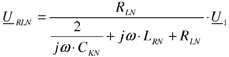
Claims (14)
- System for contactless data and energy supply of bus subscriber modules that can be lined up next to each other on a subbase, whereby the subbase has an energy transmission interface (5) and a data transmission interface (6) and where the bus subscriber modules (2) in each case have a corresponding energy transmission interface (7) and a corresponding data transmission interface (8), characterized in that the subbase is made as a mounting rail, which is provided with one supply bar (4) that extends along the main extension direction of the mounting rail (1) and which displays the energy transmission interface (5) and the data transmission interface (6)wherein the assembly rail is made as mounting rail (1) with a hat-shaped cross-section upon which one can arrest the bus subscriber modules (2) and which can be lined up against each other in a grid-free manner, and has a free space (3), whereby the supply bar (4) is integrated at least partly or preferably inserted in the free space (3).
- System according to Claim 1 characterized in that the bus subscriber module (2) can be freely positioned on mounting rail (1) in the latter's main extension direction in a grid-free fashion and that the supply bar extends in the lineup over more than one bus subscriber module and that the supply bar (4) has a support structure upon which are placed for inductive and/or capacitive coupling at least one or several inductivities and/or electrodes.
- System according to Claim 1 or 2, characterized in that the supply bar (4) has a projection (25) that sticks out over the free space (3) in the mounting rail (1) and that the bus subscriber modules (2) have a recess (26) in which engages the projection (25) in the state mounted on mounting rail (1).
- System according to one of the above claims, characterized in that the energy transmission interface (5) and/or the data transmission interface (6) is/are designed for inductive contactless transmission and in each case have a primary-side inductivity, and that the energy transmission interface (7) and/or the corresponding data transmission interface (8) of the bus subscriber module (2) is/are designed for inductive contactless transmission and in each case have a secondary-side inductivity or that the energy transmission interface (5) and/or the data transmission interface (6) is/are designed for capacitive contactless transmission and that the energy transmission interface (7) and/or the corresponding data transmission interface (8) of the bus subscriber modules (2) is/are designed for capacitive contactless transmission.
- System according to claim 4, characterized in thata. the primary-side inductivity (inductivities) of the energy transmission interface (5) and/or the data transmission interface (6) in each case are designed for energy and data transmission to several secondary-side inductivities of the bus subscriber modules orb. the energy transmission interface (5) and/or the data transmission interface (6) in each case display an electrode, in particular, a strip conductor, which is designed for capacitive energy and data transmission toward several secondary-side electrodes of the bus subscriber modules.
- System according to claim 4 or 5, characterized in that the primary-side inductivity as a means for the adjustment of positioning inaccuracies has a different structural width in the Y direction perpendicularly to the mounting rail when compared to the secondary-side inductivities and/or that primary and secondary-side electrodes (30, 31) are made perpendicularly to the mounting rail level in the X-Y direction on side legs [with] mutually engaging projections (33) and recesses (32) on the supply bar (4) and on the bus subscriber modules (2).
- System according to one of the above claims, characterized in that the electrodes are aligned perpendicularly to the mounting rail level in the X-Y direction on the side legs of the mutually engaging projections and recesses on the supply bar and on the bus subscriber modules are arranged with different width in the Z direction perpendicularly to the mounting rail in order to adjust positioning inaccuracies.
- System according to one of the above claims, characterized in that the strip conductors on the supply bar (4) have a structural width that can be changed along the main extension direction in the Y direction.
- System according to one of the above claims, characterized in that it has a control device which is designed to adjust the system as a function of the number of the bus subscriber modules that are set upon the mounting rail.
- System according to one of the above claims, characterized in that it has a control device, which is designed to determine the number of bus subscriber modules that are set upon the mounting rail from at least one determinable critical parameter and to adjust the system as a function of the number of the bus subscriber modules set upon the mounting rail and/or it has a control device, which is designed to determine the absolute order of the bus subscriber modules that are set upon the mounting rail.
- System according to one of the above claims, characterized in that it has a Gateway module (13) and that the Gateway module preferably is provided with the control device wherein preferably that the Gateway module (13) is connected by one or several electrical line(s) (cables) with the supply bar (4) and is tied to the inductivity/capacity on the supply bar.
- System according to one of the above claims, characterized in that Gateway module (13) has the electrical and/or electronic structural elements which furthermore are necessary to implement a transmission unit or a combined transmission and receiving device and/or that connected to the Gateway module, there are several supply bars whose energy and data transmission interfaces are wired with each other via a cable connection.
- Method for the operation of a system according to one of the claims 9-11 or 12 if referring back to claims 9-11, characterized in that with the help of the control device, the number of bus subscriber modules set upon the mounting rail can be determined from at least one determinable critical parameter during energy and/or data transmission and that the system is readjusted as a function of the number of bus subscriber modules set upon the mounting rail.
- Method for the operation of a system according to one of the claims 9-11 or 12 if referring back to claims 9-11, characterized in that absolute site of the bus subscriber modules set upon the mounting rail is determined with the help of the control device.
Applications Claiming Priority (2)
| Application Number | Priority Date | Filing Date | Title |
|---|---|---|---|
| DE102009003846A DE102009003846A1 (en) | 2009-04-29 | 2009-04-29 | System for the contactless energy and data supply of bus subscriber modules |
| PCT/EP2010/055600 WO2010125048A1 (en) | 2009-04-29 | 2010-04-27 | System for supplying bus subscriber modules with contactless energy and data |
Publications (3)
| Publication Number | Publication Date |
|---|---|
| EP2425588A1 EP2425588A1 (en) | 2012-03-07 |
| EP2425588B1 true EP2425588B1 (en) | 2017-03-15 |
| EP2425588B2 EP2425588B2 (en) | 2020-02-12 |
Family
ID=42289358
Family Applications (1)
| Application Number | Title | Priority Date | Filing Date |
|---|---|---|---|
| EP10720371.3A Active EP2425588B2 (en) | 2009-04-29 | 2010-04-27 | System for supplying bus subscriber modules with contactless energy and data |
Country Status (6)
| Country | Link |
|---|---|
| US (1) | US9099880B2 (en) |
| EP (1) | EP2425588B2 (en) |
| JP (2) | JP2012525752A (en) |
| CN (1) | CN102415055B (en) |
| DE (1) | DE102009003846A1 (en) |
| WO (1) | WO2010125048A1 (en) |
Families Citing this family (34)
| Publication number | Priority date | Publication date | Assignee | Title |
|---|---|---|---|---|
| JP2012186796A (en) | 2011-02-18 | 2012-09-27 | Sony Corp | Signal transmission device and electronic apparatus |
| US9941930B2 (en) * | 2011-08-16 | 2018-04-10 | Philips Lighting Holding B.V. | Conductive layer of a large surface for distribution of power using capacitive power transfer |
| CN103875161B (en) * | 2011-08-16 | 2017-02-15 | 皇家飞利浦有限公司 | A wireless power converter utilized as a capacitive power transfer system |
| WO2013024432A2 (en) * | 2011-08-16 | 2013-02-21 | Koninklijke Philips Electronics N.V. | A capacitive contactless powering system |
| DE102012000409A1 (en) | 2012-01-12 | 2013-07-18 | Phoenix Contact Gmbh & Co. Kg | Modular data system with inductive energy transfer |
| DE102012000411B4 (en) | 2012-01-12 | 2018-03-01 | Phoenix Contact Gmbh & Co. Kg | Inductive energy transformer |
| DE102012000408A1 (en) | 2012-01-12 | 2013-07-18 | Phoenix Contact Gmbh & Co. Kg | Resonant inductive power supply device |
| WO2013152972A1 (en) * | 2012-04-12 | 2013-10-17 | Tyco Electronics Amp Gmbh | System for the contactless data supply of bus participant modules |
| WO2014006685A1 (en) * | 2012-07-02 | 2014-01-09 | 富士機械製造株式会社 | Capacitive coupling contactless power supply device |
| JP6058003B2 (en) * | 2012-07-11 | 2017-01-11 | 富士機械製造株式会社 | Electrostatic coupling type non-contact power feeding device |
| DE102012110172B4 (en) * | 2012-10-24 | 2017-11-16 | Phoenix Contact Gmbh & Co. Kg | Bus system with AC power supply |
| DE102012110170B4 (en) * | 2012-10-24 | 2018-05-24 | Phoenix Contact Gmbh & Co. Kg | Modular bus system for the transmission of data and / or energy |
| EP3020116B1 (en) * | 2013-07-11 | 2017-04-26 | Philips Lighting Holding B.V. | Capacitive powering system with increased efficiency |
| JP6322391B2 (en) * | 2013-11-20 | 2018-05-09 | ハンファテクウィン株式会社Hanwha Techwin Co.,Ltd. | Work machine |
| JP2015133815A (en) * | 2014-01-10 | 2015-07-23 | 船井電機株式会社 | Power feeding device, power feeding method, and power receiving device |
| DE102014219572A1 (en) * | 2014-09-26 | 2016-03-31 | Phoenix Contact Gmbh & Co. Kg | System with electronic modules that can be connected to each other |
| CN104816646B (en) * | 2015-04-02 | 2017-06-06 | 西安交通大学 | A kind of radio energy transmission system for moving static Campatible electric automobile |
| JP6573199B2 (en) * | 2016-02-04 | 2019-09-11 | パナソニックIpマネジメント株式会社 | Wireless power transmission system and power transmission device |
| JP6692078B2 (en) * | 2016-02-19 | 2020-05-13 | パナソニックIpマネジメント株式会社 | Electric device |
| CN109952624B (en) * | 2016-11-15 | 2022-05-27 | 株式会社富士 | Non-contact power supply device and working machine |
| JP6817604B2 (en) * | 2017-03-24 | 2021-01-20 | パナソニックIpマネジメント株式会社 | Transmission equipment and wireless power transmission system |
| JPWO2019069348A1 (en) * | 2017-10-02 | 2019-11-14 | 三菱電機株式会社 | Electronics |
| DE102018109267A1 (en) * | 2018-04-18 | 2019-10-24 | Balluff Gmbh | Fastener for electrical equipment |
| DE202018103319U1 (en) * | 2018-06-13 | 2019-09-16 | Wago Verwaltungsgesellschaft Mbh | Sensor device for a terminal block assembly, terminal block assembly, terminal block, control cabinet and read-out device |
| DE102018130342A1 (en) * | 2018-11-29 | 2020-06-04 | Liebherr-Components Biberach Gmbh | Switchgear assembly |
| BE1027224B1 (en) | 2019-04-24 | 2020-11-23 | Phoenix Contact Gmbh & Co | Modular switch for use in a data transmission and control system |
| DE102019118712A1 (en) * | 2019-07-10 | 2021-01-14 | Endress+Hauser Conducta Gmbh+Co. Kg | Field device and remote station |
| DE102019127195A1 (en) | 2019-10-09 | 2021-04-15 | Phoenix Contact Gmbh & Co. Kg | Modular interface system for connecting a control device and field devices |
| BE1028102B1 (en) * | 2020-02-28 | 2021-09-27 | Phoenix Contact Gmbh & Co | Busbar adapter for the electrical connection of at least one plug-in module to at least one busbar |
| DE102021106522A1 (en) | 2020-03-27 | 2021-09-30 | Phoenix Contact Gmbh & Co. Kg | Backplane module for the electrical connection of several function modules and a modular communication system |
| JP7600607B2 (en) | 2020-10-14 | 2024-12-17 | オムロン株式会社 | Wireless power supply device |
| WO2022096043A2 (en) | 2020-11-07 | 2022-05-12 | Futismo | Modular electronics |
| US20230361599A1 (en) * | 2022-05-03 | 2023-11-09 | Kamil Podhola | Wireless electromagnetic energy transfer system |
| PL131775U1 (en) * | 2023-11-03 | 2025-05-05 | Instytut Techniki Górniczej Komag | Explosion-proof capacitive coupling assembly for power transmission system |
Citations (7)
| Publication number | Priority date | Publication date | Assignee | Title |
|---|---|---|---|---|
| DE19600997A1 (en) | 1996-01-12 | 1997-07-17 | Phoenix Contact Gmbh & Co | Signals processing network bus-system for data transmission between subscribers |
| DE29624219U1 (en) | 1996-01-12 | 2001-03-01 | Phoenix Contact Gmbh & Co., 32825 Blomberg | Bus system |
| DE10203765B4 (en) | 2002-01-31 | 2006-11-30 | Rexroth Mecman Gmbh | Electromagnetic multi-way valve with a non-contact electrical power transmission |
| EP1739804A1 (en) | 2005-07-01 | 2007-01-03 | BAUMÜLLER ANLAGEN-SYSTEMTECHNIK GmbH & Co. | Rail for electrically conductive support of one or more electrical devices |
| EP1885085A1 (en) | 2006-08-01 | 2008-02-06 | Siemens Aktiengesellschaft | Contactless means for supplying energy and data to bus users |
| US20080303351A1 (en) | 2005-12-02 | 2008-12-11 | Koninklijke Philips Electronics, N.V. | Coupling System |
| EP2073315A2 (en) | 2007-12-18 | 2009-06-24 | Phoenix Contact GmbH & Co. KG | Modular data transfer system with separate energy supply for each activated module |
Family Cites Families (22)
| Publication number | Priority date | Publication date | Assignee | Title |
|---|---|---|---|---|
| JPS63117630A (en) * | 1986-11-05 | 1988-05-21 | サムタク株式会社 | Source circuit for movable equipment |
| JPS63253836A (en) * | 1987-04-07 | 1988-10-20 | 東京軽電機株式会社 | Power transmitter |
| JPH0740266A (en) * | 1993-07-29 | 1995-02-10 | Yaskawa Electric Corp | Direct acting loader |
| EP0748024B1 (en) * | 1994-02-21 | 1999-09-15 | Kabushiki Kaisha Yaskawa Denki | Direct-acting non-contact feeder |
| JPH0865926A (en) * | 1994-08-23 | 1996-03-08 | Yaskawa Electric Corp | Autonomous pneumatic pressure generator |
| JP3724516B2 (en) * | 1995-02-14 | 2005-12-07 | 株式会社安川電機 | Contactless motion transmission device |
| JPH0974032A (en) * | 1995-09-04 | 1997-03-18 | Yaskawa Electric Corp | Contactless transmission device |
| DE19612575C2 (en) * | 1996-03-29 | 1999-11-18 | Endress Hauser Gmbh Co | Device for the detachable fastening of devices and for their electrical connection |
| JP3846644B2 (en) * | 1996-04-12 | 2006-11-15 | 株式会社安川電機 | Contactless transmission device |
| JP3374668B2 (en) * | 1996-09-09 | 2003-02-10 | 株式会社豊田自動織機 | Mobile communication method and communication system |
| DE19640367A1 (en) * | 1996-09-30 | 1998-04-02 | Siemens Ag | Wireless energy and data transmission for a modular peripheral system |
| JPH10215530A (en) * | 1997-01-28 | 1998-08-11 | Matsushita Electric Works Ltd | Non-contact power transmission device |
| JP3838286B2 (en) * | 1997-01-31 | 2006-10-25 | 株式会社安川電機 | Direct acting contactless transmission equipment |
| JP2000116036A (en) * | 1998-09-29 | 2000-04-21 | Yamaha Motor Co Ltd | Transportation equipment |
| JP2000134809A (en) * | 1998-10-28 | 2000-05-12 | Panetto:Kk | Charging device with high-frequency power supply |
| DE19922363A1 (en) * | 1999-05-14 | 2000-11-23 | Rexroth Star Gmbh | Device for determining the relative position of two bodies movable relative to one another and method for producing such a device |
| US6498305B1 (en) * | 1999-05-25 | 2002-12-24 | Intel Corporation | Interconnect mechanics for electromagnetic coupler |
| DE10026174A1 (en) * | 2000-04-18 | 2001-10-31 | Schleifring Und Appbau Gmbh | Capacitive bus |
| US20090314829A1 (en) * | 2007-05-22 | 2009-12-24 | Mcallistor Clarke | Systems, Methods, and Devices for Replication of Data onto Wireless Sensors |
| DE202006018152U1 (en) | 2006-11-28 | 2008-04-10 | Weidmüller Interface GmbH & Co. KG | Additional connection for terminal blocks |
| DE202007005373U1 (en) | 2007-04-12 | 2008-08-21 | Weidmüller Interface GmbH & Co. KG | Modular terminal block system |
| JP5335225B2 (en) * | 2007-11-30 | 2013-11-06 | 三重電子株式会社 | Guide device |
-
2009
- 2009-04-29 DE DE102009003846A patent/DE102009003846A1/en not_active Withdrawn
-
2010
- 2010-04-27 EP EP10720371.3A patent/EP2425588B2/en active Active
- 2010-04-27 JP JP2012507711A patent/JP2012525752A/en active Pending
- 2010-04-27 CN CN201080018996.9A patent/CN102415055B/en active Active
- 2010-04-27 US US13/264,928 patent/US9099880B2/en active Active
- 2010-04-27 WO PCT/EP2010/055600 patent/WO2010125048A1/en not_active Ceased
-
2014
- 2014-01-23 JP JP2014010256A patent/JP5928495B2/en not_active Expired - Fee Related
Patent Citations (7)
| Publication number | Priority date | Publication date | Assignee | Title |
|---|---|---|---|---|
| DE19600997A1 (en) | 1996-01-12 | 1997-07-17 | Phoenix Contact Gmbh & Co | Signals processing network bus-system for data transmission between subscribers |
| DE29624219U1 (en) | 1996-01-12 | 2001-03-01 | Phoenix Contact Gmbh & Co., 32825 Blomberg | Bus system |
| DE10203765B4 (en) | 2002-01-31 | 2006-11-30 | Rexroth Mecman Gmbh | Electromagnetic multi-way valve with a non-contact electrical power transmission |
| EP1739804A1 (en) | 2005-07-01 | 2007-01-03 | BAUMÜLLER ANLAGEN-SYSTEMTECHNIK GmbH & Co. | Rail for electrically conductive support of one or more electrical devices |
| US20080303351A1 (en) | 2005-12-02 | 2008-12-11 | Koninklijke Philips Electronics, N.V. | Coupling System |
| EP1885085A1 (en) | 2006-08-01 | 2008-02-06 | Siemens Aktiengesellschaft | Contactless means for supplying energy and data to bus users |
| EP2073315A2 (en) | 2007-12-18 | 2009-06-24 | Phoenix Contact GmbH & Co. KG | Modular data transfer system with separate energy supply for each activated module |
Also Published As
| Publication number | Publication date |
|---|---|
| EP2425588A1 (en) | 2012-03-07 |
| US9099880B2 (en) | 2015-08-04 |
| JP5928495B2 (en) | 2016-06-01 |
| CN102415055B (en) | 2016-02-24 |
| EP2425588B2 (en) | 2020-02-12 |
| CN102415055A (en) | 2012-04-11 |
| JP2014132821A (en) | 2014-07-17 |
| JP2012525752A (en) | 2012-10-22 |
| DE102009003846A1 (en) | 2010-11-04 |
| WO2010125048A1 (en) | 2010-11-04 |
| US20120091818A1 (en) | 2012-04-19 |
Similar Documents
| Publication | Publication Date | Title |
|---|---|---|
| EP2425588B1 (en) | System for supplying bus subscriber modules with contactless energy and data | |
| EP1275208B1 (en) | Arrangement for contactless transmission of electrical signals or energy | |
| DE10304584A1 (en) | Communication of power and data to sensors and actuators in a process uses field transmission and avoids wiring | |
| DE112016007231T5 (en) | Wireless energy transmitter, wireless energy transmission system and method for driving a wireless power transmission system | |
| EP2803142B1 (en) | Modular data system having inductive energy transfer | |
| EP2409665A1 (en) | Medical treatment device | |
| DE112017008098T5 (en) | Dynamic transmission coil positioning system, wireless energy transmission system and method for positioning a transmission coil | |
| WO2020002229A1 (en) | Switching device for a coil | |
| DE102022125039A1 (en) | Inductive charging device for a vehicle charging system | |
| WO2020070115A1 (en) | Device for non-contact inductive energy transfer, in particular for inductive charging processes in motor vehicles | |
| EP3485499B1 (en) | Coil assembly | |
| DE10141884B4 (en) | Feed circuit of a resonance circuit generating a magnetic field and control device for this | |
| BE1029400B1 (en) | Contact monitoring device for a three-pole changeover contact | |
| DE102005013293B4 (en) | Magnetic resonance system with a high-frequency source | |
| DE102012216417A1 (en) | Device i.e. charger, for wireless transmission of electrical power to electric appliance e.g. mobile phone, has inductotors connected with load circuit and voltage source, and another inductors arranged in electric appliance | |
| EP2284848B1 (en) | Transmitter | |
| DE112021007985T5 (en) | CONTACTLESS ENERGY SUPPLY DEVICE, CONTACTLESS ENERGY SUPPLY SYSTEM, ELEVATOR, AND LINEAR CONVEYOR | |
| DE102004038837B4 (en) | Electronic anti-theft system with correlated transmit / receive antennas | |
| US9870860B2 (en) | System for supplying bus subscriber modules with contactless energy and data | |
| DE10152863A1 (en) | Magnetic field generating device with several resonant circuits has series circuit of first winding, resonance capacitor(s), variable inductance(s) or capacitance(s), second winding(s) | |
| DE102010062462A1 (en) | Antenna system for transmission arrangement used in keyless entry system installed in vehicle e.g. motor car, has two antennas comprising respective windings that are electrically coupled with one another | |
| WO2020007811A2 (en) | Circuit for signal connection, device for inductive power transfer and for signal transfer, and method for producing same | |
| WO2024037751A1 (en) | Inductive charging device for a vehicle charging system | |
| DE102022111529A1 (en) | Power supply arrangement, plasma generation device and method for controlling several plasma processes | |
| EP1176854A2 (en) | Reduction of the voltage between the socket connections of ballasts for gas discharge lamps |
Legal Events
| Date | Code | Title | Description |
|---|---|---|---|
| PUAI | Public reference made under article 153(3) epc to a published international application that has entered the european phase |
Free format text: ORIGINAL CODE: 0009012 |
|
| 17P | Request for examination filed |
Effective date: 20111124 |
|
| AK | Designated contracting states |
Kind code of ref document: A1 Designated state(s): AT BE BG CH CY CZ DE DK EE ES FI FR GB GR HR HU IE IS IT LI LT LU LV MC MK MT NL NO PL PT RO SE SI SK SM TR |
|
| DAX | Request for extension of the european patent (deleted) | ||
| GRAP | Despatch of communication of intention to grant a patent |
Free format text: ORIGINAL CODE: EPIDOSNIGR1 |
|
| INTG | Intention to grant announced |
Effective date: 20161114 |
|
| GRAS | Grant fee paid |
Free format text: ORIGINAL CODE: EPIDOSNIGR3 |
|
| GRAA | (expected) grant |
Free format text: ORIGINAL CODE: 0009210 |
|
| AK | Designated contracting states |
Kind code of ref document: B1 Designated state(s): AT BE BG CH CY CZ DE DK EE ES FI FR GB GR HR HU IE IS IT LI LT LU LV MC MK MT NL NO PL PT RO SE SI SK SM TR |
|
| REG | Reference to a national code |
Ref country code: CH Ref legal event code: EP Ref country code: GB Ref legal event code: FG4D Free format text: NOT ENGLISH |
|
| REG | Reference to a national code |
Ref country code: IE Ref legal event code: FG4D Free format text: LANGUAGE OF EP DOCUMENT: GERMAN |
|
| REG | Reference to a national code |
Ref country code: AT Ref legal event code: REF Ref document number: 876578 Country of ref document: AT Kind code of ref document: T Effective date: 20170415 |
|
| REG | Reference to a national code |
Ref country code: DE Ref legal event code: R096 Ref document number: 502010013308 Country of ref document: DE |
|
| REG | Reference to a national code |
Ref country code: NL Ref legal event code: MP Effective date: 20170315 |
|
| REG | Reference to a national code |
Ref country code: LT Ref legal event code: MG4D |
|
| PG25 | Lapsed in a contracting state [announced via postgrant information from national office to epo] |
Ref country code: LT Free format text: LAPSE BECAUSE OF FAILURE TO SUBMIT A TRANSLATION OF THE DESCRIPTION OR TO PAY THE FEE WITHIN THE PRESCRIBED TIME-LIMIT Effective date: 20170315 Ref country code: FI Free format text: LAPSE BECAUSE OF FAILURE TO SUBMIT A TRANSLATION OF THE DESCRIPTION OR TO PAY THE FEE WITHIN THE PRESCRIBED TIME-LIMIT Effective date: 20170315 Ref country code: GR Free format text: LAPSE BECAUSE OF FAILURE TO SUBMIT A TRANSLATION OF THE DESCRIPTION OR TO PAY THE FEE WITHIN THE PRESCRIBED TIME-LIMIT Effective date: 20170616 Ref country code: NO Free format text: LAPSE BECAUSE OF FAILURE TO SUBMIT A TRANSLATION OF THE DESCRIPTION OR TO PAY THE FEE WITHIN THE PRESCRIBED TIME-LIMIT Effective date: 20170615 Ref country code: HR Free format text: LAPSE BECAUSE OF FAILURE TO SUBMIT A TRANSLATION OF THE DESCRIPTION OR TO PAY THE FEE WITHIN THE PRESCRIBED TIME-LIMIT Effective date: 20170315 |
|
| PG25 | Lapsed in a contracting state [announced via postgrant information from national office to epo] |
Ref country code: BG Free format text: LAPSE BECAUSE OF FAILURE TO SUBMIT A TRANSLATION OF THE DESCRIPTION OR TO PAY THE FEE WITHIN THE PRESCRIBED TIME-LIMIT Effective date: 20170615 Ref country code: LV Free format text: LAPSE BECAUSE OF FAILURE TO SUBMIT A TRANSLATION OF THE DESCRIPTION OR TO PAY THE FEE WITHIN THE PRESCRIBED TIME-LIMIT Effective date: 20170315 Ref country code: SE Free format text: LAPSE BECAUSE OF FAILURE TO SUBMIT A TRANSLATION OF THE DESCRIPTION OR TO PAY THE FEE WITHIN THE PRESCRIBED TIME-LIMIT Effective date: 20170315 |
|
| PG25 | Lapsed in a contracting state [announced via postgrant information from national office to epo] |
Ref country code: NL Free format text: LAPSE BECAUSE OF FAILURE TO SUBMIT A TRANSLATION OF THE DESCRIPTION OR TO PAY THE FEE WITHIN THE PRESCRIBED TIME-LIMIT Effective date: 20170315 |
|
| PG25 | Lapsed in a contracting state [announced via postgrant information from national office to epo] |
Ref country code: SK Free format text: LAPSE BECAUSE OF FAILURE TO SUBMIT A TRANSLATION OF THE DESCRIPTION OR TO PAY THE FEE WITHIN THE PRESCRIBED TIME-LIMIT Effective date: 20170315 Ref country code: IT Free format text: LAPSE BECAUSE OF FAILURE TO SUBMIT A TRANSLATION OF THE DESCRIPTION OR TO PAY THE FEE WITHIN THE PRESCRIBED TIME-LIMIT Effective date: 20170315 Ref country code: CZ Free format text: LAPSE BECAUSE OF FAILURE TO SUBMIT A TRANSLATION OF THE DESCRIPTION OR TO PAY THE FEE WITHIN THE PRESCRIBED TIME-LIMIT Effective date: 20170315 Ref country code: EE Free format text: LAPSE BECAUSE OF FAILURE TO SUBMIT A TRANSLATION OF THE DESCRIPTION OR TO PAY THE FEE WITHIN THE PRESCRIBED TIME-LIMIT Effective date: 20170315 Ref country code: ES Free format text: LAPSE BECAUSE OF FAILURE TO SUBMIT A TRANSLATION OF THE DESCRIPTION OR TO PAY THE FEE WITHIN THE PRESCRIBED TIME-LIMIT Effective date: 20170315 Ref country code: RO Free format text: LAPSE BECAUSE OF FAILURE TO SUBMIT A TRANSLATION OF THE DESCRIPTION OR TO PAY THE FEE WITHIN THE PRESCRIBED TIME-LIMIT Effective date: 20170315 |
|
| PG25 | Lapsed in a contracting state [announced via postgrant information from national office to epo] |
Ref country code: IS Free format text: LAPSE BECAUSE OF FAILURE TO SUBMIT A TRANSLATION OF THE DESCRIPTION OR TO PAY THE FEE WITHIN THE PRESCRIBED TIME-LIMIT Effective date: 20170715 Ref country code: PT Free format text: LAPSE BECAUSE OF FAILURE TO SUBMIT A TRANSLATION OF THE DESCRIPTION OR TO PAY THE FEE WITHIN THE PRESCRIBED TIME-LIMIT Effective date: 20170717 Ref country code: SM Free format text: LAPSE BECAUSE OF FAILURE TO SUBMIT A TRANSLATION OF THE DESCRIPTION OR TO PAY THE FEE WITHIN THE PRESCRIBED TIME-LIMIT Effective date: 20170315 Ref country code: PL Free format text: LAPSE BECAUSE OF FAILURE TO SUBMIT A TRANSLATION OF THE DESCRIPTION OR TO PAY THE FEE WITHIN THE PRESCRIBED TIME-LIMIT Effective date: 20170315 |
|
| REG | Reference to a national code |
Ref country code: CH Ref legal event code: PL |
|
| REG | Reference to a national code |
Ref country code: DE Ref legal event code: R026 Ref document number: 502010013308 Country of ref document: DE |
|
| PLBI | Opposition filed |
Free format text: ORIGINAL CODE: 0009260 |
|
| PLAX | Notice of opposition and request to file observation + time limit sent |
Free format text: ORIGINAL CODE: EPIDOSNOBS2 |
|
| 26 | Opposition filed |
Opponent name: SEW-EURODRIVE GMBH & CO. KG Effective date: 20171204 |
|
| REG | Reference to a national code |
Ref country code: IE Ref legal event code: MM4A |
|
| REG | Reference to a national code |
Ref country code: FR Ref legal event code: ST Effective date: 20171229 |
|
| PG25 | Lapsed in a contracting state [announced via postgrant information from national office to epo] |
Ref country code: DK Free format text: LAPSE BECAUSE OF FAILURE TO SUBMIT A TRANSLATION OF THE DESCRIPTION OR TO PAY THE FEE WITHIN THE PRESCRIBED TIME-LIMIT Effective date: 20170315 Ref country code: FR Free format text: LAPSE BECAUSE OF NON-PAYMENT OF DUE FEES Effective date: 20170515 Ref country code: MC Free format text: LAPSE BECAUSE OF FAILURE TO SUBMIT A TRANSLATION OF THE DESCRIPTION OR TO PAY THE FEE WITHIN THE PRESCRIBED TIME-LIMIT Effective date: 20170315 |
|
| GBPC | Gb: european patent ceased through non-payment of renewal fee |
Effective date: 20170615 |
|
| PG25 | Lapsed in a contracting state [announced via postgrant information from national office to epo] |
Ref country code: LU Free format text: LAPSE BECAUSE OF NON-PAYMENT OF DUE FEES Effective date: 20170427 Ref country code: LI Free format text: LAPSE BECAUSE OF NON-PAYMENT OF DUE FEES Effective date: 20170430 Ref country code: SI Free format text: LAPSE BECAUSE OF FAILURE TO SUBMIT A TRANSLATION OF THE DESCRIPTION OR TO PAY THE FEE WITHIN THE PRESCRIBED TIME-LIMIT Effective date: 20170315 Ref country code: CH Free format text: LAPSE BECAUSE OF NON-PAYMENT OF DUE FEES Effective date: 20170430 |
|
| REG | Reference to a national code |
Ref country code: BE Ref legal event code: MM Effective date: 20170430 |
|
| PG25 | Lapsed in a contracting state [announced via postgrant information from national office to epo] |
Ref country code: IE Free format text: LAPSE BECAUSE OF NON-PAYMENT OF DUE FEES Effective date: 20170427 Ref country code: GB Free format text: LAPSE BECAUSE OF NON-PAYMENT OF DUE FEES Effective date: 20170615 |
|
| PLBB | Reply of patent proprietor to notice(s) of opposition received |
Free format text: ORIGINAL CODE: EPIDOSNOBS3 |
|
| PG25 | Lapsed in a contracting state [announced via postgrant information from national office to epo] |
Ref country code: BE Free format text: LAPSE BECAUSE OF NON-PAYMENT OF DUE FEES Effective date: 20170430 |
|
| REG | Reference to a national code |
Ref country code: AT Ref legal event code: MM01 Ref document number: 876578 Country of ref document: AT Kind code of ref document: T Effective date: 20170427 |
|
| PG25 | Lapsed in a contracting state [announced via postgrant information from national office to epo] |
Ref country code: AT Free format text: LAPSE BECAUSE OF NON-PAYMENT OF DUE FEES Effective date: 20170427 |
|
| PG25 | Lapsed in a contracting state [announced via postgrant information from national office to epo] |
Ref country code: MT Free format text: LAPSE BECAUSE OF FAILURE TO SUBMIT A TRANSLATION OF THE DESCRIPTION OR TO PAY THE FEE WITHIN THE PRESCRIBED TIME-LIMIT Effective date: 20170315 |
|
| PG25 | Lapsed in a contracting state [announced via postgrant information from national office to epo] |
Ref country code: HU Free format text: LAPSE BECAUSE OF FAILURE TO SUBMIT A TRANSLATION OF THE DESCRIPTION OR TO PAY THE FEE WITHIN THE PRESCRIBED TIME-LIMIT; INVALID AB INITIO Effective date: 20100427 |
|
| PG25 | Lapsed in a contracting state [announced via postgrant information from national office to epo] |
Ref country code: CY Free format text: LAPSE BECAUSE OF NON-PAYMENT OF DUE FEES Effective date: 20170315 |
|
| PG25 | Lapsed in a contracting state [announced via postgrant information from national office to epo] |
Ref country code: MK Free format text: LAPSE BECAUSE OF FAILURE TO SUBMIT A TRANSLATION OF THE DESCRIPTION OR TO PAY THE FEE WITHIN THE PRESCRIBED TIME-LIMIT Effective date: 20170315 |
|
| PUAH | Patent maintained in amended form |
Free format text: ORIGINAL CODE: 0009272 |
|
| STAA | Information on the status of an ep patent application or granted ep patent |
Free format text: STATUS: PATENT MAINTAINED AS AMENDED |
|
| 27A | Patent maintained in amended form |
Effective date: 20200212 |
|
| AK | Designated contracting states |
Kind code of ref document: B2 Designated state(s): AT BE BG CH CY CZ DE DK EE ES FI FR GB GR HR HU IE IS IT LI LT LU LV MC MK MT NL NO PL PT RO SE SI SK SM TR |
|
| REG | Reference to a national code |
Ref country code: DE Ref legal event code: R102 Ref document number: 502010013308 Country of ref document: DE |
|
| PG25 | Lapsed in a contracting state [announced via postgrant information from national office to epo] |
Ref country code: TR Free format text: LAPSE BECAUSE OF FAILURE TO SUBMIT A TRANSLATION OF THE DESCRIPTION OR TO PAY THE FEE WITHIN THE PRESCRIBED TIME-LIMIT Effective date: 20170315 |
|
| P01 | Opt-out of the competence of the unified patent court (upc) registered |
Effective date: 20230523 |
|
| PGFP | Annual fee paid to national office [announced via postgrant information from national office to epo] |
Ref country code: DE Payment date: 20250422 Year of fee payment: 16 |