EP2425291B1 - Auf einem kopf montierte anzeige - Google Patents
Auf einem kopf montierte anzeige Download PDFInfo
- Publication number
- EP2425291B1 EP2425291B1 EP10718666.0A EP10718666A EP2425291B1 EP 2425291 B1 EP2425291 B1 EP 2425291B1 EP 10718666 A EP10718666 A EP 10718666A EP 2425291 B1 EP2425291 B1 EP 2425291B1
- Authority
- EP
- European Patent Office
- Prior art keywords
- image
- user
- eye
- optical
- optical power
- Prior art date
- Legal status (The legal status is an assumption and is not a legal conclusion. Google has not performed a legal analysis and makes no representation as to the accuracy of the status listed.)
- Active
Links
Images


Classifications
-
- G—PHYSICS
- G02—OPTICS
- G02B—OPTICAL ELEMENTS, SYSTEMS OR APPARATUS
- G02B27/00—Optical systems or apparatus not provided for by any of the groups G02B1/00 - G02B26/00, G02B30/00
- G02B27/01—Head-up displays
- G02B27/017—Head mounted
- G02B27/0172—Head mounted characterised by optical features
-
- G—PHYSICS
- G02—OPTICS
- G02B—OPTICAL ELEMENTS, SYSTEMS OR APPARATUS
- G02B27/00—Optical systems or apparatus not provided for by any of the groups G02B1/00 - G02B26/00, G02B30/00
- G02B27/42—Diffraction optics, i.e. systems including a diffractive element being designed for providing a diffractive effect
- G02B27/4205—Diffraction optics, i.e. systems including a diffractive element being designed for providing a diffractive effect having a diffractive optical element [DOE] contributing to image formation, e.g. whereby modulation transfer function MTF or optical aberrations are relevant
-
- G—PHYSICS
- G02—OPTICS
- G02B—OPTICAL ELEMENTS, SYSTEMS OR APPARATUS
- G02B27/00—Optical systems or apparatus not provided for by any of the groups G02B1/00 - G02B26/00, G02B30/00
- G02B27/42—Diffraction optics, i.e. systems including a diffractive element being designed for providing a diffractive effect
- G02B27/4272—Diffraction optics, i.e. systems including a diffractive element being designed for providing a diffractive effect having plural diffractive elements positioned sequentially along the optical path
-
- G—PHYSICS
- G02—OPTICS
- G02B—OPTICAL ELEMENTS, SYSTEMS OR APPARATUS
- G02B27/00—Optical systems or apparatus not provided for by any of the groups G02B1/00 - G02B26/00, G02B30/00
- G02B27/42—Diffraction optics, i.e. systems including a diffractive element being designed for providing a diffractive effect
- G02B27/44—Grating systems; Zone plate systems
-
- G—PHYSICS
- G02—OPTICS
- G02B—OPTICAL ELEMENTS, SYSTEMS OR APPARATUS
- G02B27/00—Optical systems or apparatus not provided for by any of the groups G02B1/00 - G02B26/00, G02B30/00
- G02B27/01—Head-up displays
- G02B27/0101—Head-up displays characterised by optical features
- G02B2027/0123—Head-up displays characterised by optical features comprising devices increasing the field of view
-
- G—PHYSICS
- G02—OPTICS
- G02B—OPTICAL ELEMENTS, SYSTEMS OR APPARATUS
- G02B5/00—Optical elements other than lenses
- G02B5/02—Diffusing elements; Afocal elements
Definitions
- This invention relates to a head-mounted display apparatus, in which a display is provided on a surface through which a wearer of the apparatus views the outside world.
- head-mounted display apparatus include visors, goggles and spectacles worn directly on the head, and also such articles carried indirectly on the head by being mounted on a helmet, or other head gear. It also includes visors, goggles and viewing windows which are built into helmets or other head gear.
- the invention is applicable to equipment worn by military personnel, in particular infantrymen and crews of armoured fighting vehicles, aircrew and other airborne personnel (whether civil or military) who wear helmets, divers, and other personnel to whom visual information must be transmitted under difficult conditions. Examples are fire-fighters and other emergency services personnel, and the police.
- the invention may also be applicable to head-mounted virtual reality display apparatus, in which a display is provided to a wearer of the apparatus via a surface which obscures his view of the outside world.
- Prior art head-mounted display apparatus employs a flat waveguide between the user's eye and a visor of a helmet, which waveguide acts as a combiner and expands a pupil of image-bearing light to present an image to the user.
- These displays must be made small and compact because they must fit into the restricted space between the user's eye and the helmet, and this can lead to cost and complexity.
- images are projected onto the inner surface of a visor and reflected from it so as to be visible to the wearer.
- Prior art US2003086135A1 discloses a head-mounted display comprising a curved waveguide having an entrance region to couple light into the waveguide and an exit region to couple propagation light out of the waveguide.
- the entrance region and the exit region are provided with HOEs.
- the present invention seeks to provide alternatives to these prior art solutions, which may avoid some of the disadvantages thereof.
- a head-mounted or helmet-mounted display apparatus comprises: an optical element which in use is disposed in front of an eye of a user, which is curved in both azimuth and elevation relative to the eye and at least a portion of which is configured to operate as a waveguide; a source of image-bearing light; input means for coupling a pupil of image-bearing light from the source into the at least a portion of the optical element operating as a waveguide so that the pupil of image-bearing light propagates therethrough by total internal reflection; and an output diffractive element located upon a surface of a curved section of the optical element and arranged to release the propagating pupil of image-bearing light from the optical element along the curved section, the output diffractive element having further optical power which in combination with optical power of the curved section of the optical element on which the output diffractive element is located, directs the released pupil of light to converge so as to provide a visible image to the user's eye, wherein the output diffractive element includes grat
- the curved optical element may be a transparent element through which the user views the outside world.
- the image-bearing light may be introduced into the optical element for propagation therethrough via input means comprising an input reflective, diffractive or transmissive element.
- At least the output diffractive element may have spherical optical power in azimuth and elevation relative to the user's eye.
- the spherical optical power may be provided by non-parallel diffractive features of the output diffractive element.
- the output diffractive element may have an angular bandwidth which is less than the angular field of view of the visible image provided to the user's eye, the angle of diffraction of the output diffractive element varying across the element so as to present the image to the user's eye.
- an optical axis of a waveguide formed within the optical element lies in a plane containing a sagittal axis of symmetry of the optical element and an eye of the user.
- the source of image-bearing light may comprise a display panel and means for illuminating it, or a self-illuminating display panel.
- optical powers of optical element and the output diffraction element and any optical power of the input means are such that image bearing light passes from the image-bearing light source to the input means without being acted upon by an element having optical power.
- the apparatus may comprise a further output diffractive element configured with the optical element to provide a visible image to the user's other eye.
- the apparatus may comprise a respective image-bearing light source for each input means, the light source being disposed such that relative angular movement of the light sources about an axis of symmetry of the optical element adjusts the inter-pupillary spacing of the images presented to the user's eyes.
- the switching means may be an input element which is common to the first and further input means, and switchable between them.
- the image-bearing light source may be configured to modify the image synchronously with switching of the image-bearing light thereby to provide a pair of binocular images to the user's eyes.
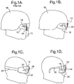
- a soldier is shown wearing a helmet 10 having a curved visor 12, through which he views the outside world.
- a light source 14 from which projects upwards a flat slab-like waveguide 16, which is disposed under the visor in front of the user's eye 18.
- An image from the source 14 is propagated through the waveguide and diffracted out to the user's eye as a visible image. Whilst effective, this arrangement can be costly, and the presence of the waveguide close to the user's eye can present a hazard.
- part 20 of the curved visor of the helmet is itself used as the waveguide.
- the light source 14 is shown here mounted outside the helmet, but it can be placed inside subject to space being available, and to it being located so as not to present a hazard to the user.
- a pair of goggles which can be worn alone or under a visorless helmet, comprises a curved visor 22, held onto the user's head by an elasticated strap 24.
- a portion 26 of the visor is configured to operate as a waveguide, receiving image-bearing light from a source 14 and delivering it to the user's eye 18.
- the curved lens portions 28 of a pair of spectacles 30 include a waveguide portion 32 driven by a light source 14 to deliver an image to the user's eye 18.
- the visor 12 of figure 1B comprises an input diffractive element or grating 34, an output diffractive element or grating 36 angularly spaced from the input element vertically around the visor.
- the waveguide portion 20 of the visor lies between the input and output diffractive elements.
- the light source 14 delivers image-bearing light to the input element 34, from which it propagates through the waveguide portion 20, under total internal reflection, to the output element 36 at thence is delivered to the user's eye 18.
- Figure 2C shows a preferred arrangement in which the light source 14 is diagonally offset around the visor so that it is disposed above the other eye 38 of the user.
- the waveguide portion passes through an axis of symmetry 42 of the waveguide portion 20 of the visor 14, lying in the mid-sagittal plane 43 of the user's head.
- the visor at least in this region, is of spherical shape, and is symmetrical about the mid-sagittal plane 43. This allows the use of a single continuous curved visor structure rather than having to deploy a visor made of several non-continuous surfaces.
- the waveguide guide may have different radii of curvature in azimuth and elevation.
- the invention requires a pupil of image-bearing light to be conveyed from the image source to the user's eye. This is achieved by supplementing the optical power inherent in the curvature of the waveguide portion 20 of the visor 14 (it is of constant thickness between parallel curved surfaces) with optical power in at least the output diffracting element 36, and if appropriate in the input diffracting element as well.
- the extra optical power is obtained by adding spherical power in the azimuthal plane of the output diffractive element 36 in front of the eye.
- the spherical power is provided in both azimuth and elevation relative to the user's eye 18.
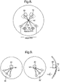
- a conventional straight-ruled grating 44 would not converge diffracting light to a pupil at the user's eye. If the grating instead has increased spherical power, as showing at 46 in figure 3B , convergence to a pupil at the eye is achieved.
- the spherical power is provided by curving the grating lines 48 upwards gradually across their length and varying their spacing relative to the centre of the grating, thereby providing a diffractive component orthogonally to the main sideways extent of the grating lines.
- figure 4A shows how the conventional grating 44 of figure 3A diffracts parallel rays of light 45 incident anywhere on its surface through the same angle so that they remain parallel after diffraction.
- the grating has zero optical power (infinite focal length).
- the grating lines 48 are curved upwards, whilst maintaining the same even spacing as the grating lines 44 of figure 3A . Incident parallel rays remain parallel after diffraction when viewed in elevation as at 47, but are convergent when viewed in the azimuthal plane.
- the spacing of the grating lines is reduced as a function of the distance y from the horizontal centre line of the grating ( figure 4C ), parallel incident rays also are convergent after diffraction in the elevational plane.
- the grating can be given spherical and/or cylindrical optical power.
- these elements can be given optical power in either or both of the azimuthal and elevational planes (i.e. spherical and/or cylindrical optical power).
- the necessary curvature and spacing of the grating lines can be determined either by optical calculation methods or by iterative simulation.
- the portion 20 of the visor which acts as a waveguide is of part-spherical shape and of constant thickness. It thereby has spherical optical power with respect to light propagating through it from the input to the output diffractive elements.
- the optical powers of the waveguide and these two elements are chosen and combined using optical calculation methods or by iterative simulation so that the elements 34, 20 and 36 behave as a lens system to deliver a visible image to the user's eye.
- Figures 5A to 5D show various forms of image-generating light sources which may be used in the invention.
- light from a point source 50 passes through a beam splitter 52 to illuminate the surface of a reflective display panel 54.
- Light reflected from the panel, now image-bearing, is reflected at the beam splitter through a focussing lens 60 to the input diffracting element 34 at thence to the user's eye 18 as already described.
- the display panel 54 is transmissive rather than reflective. Light from the source 50 passes through the display panel and the lens 60 to the input diffracting element 34 as before.
- the display panel 54 is self-illuminated.
- it may be an organic light emitting diode matrix.
- Light from the display passes through the lens 60 to the input diffractive element 34.
- the functionality of the focussing lens 60 is achieved within the diffracting means 34, 36 and the waveguide 20.
- the focussing power of the lens may be achieved in the input diffracting element 34.
- the complex optical power of the lens system 60 which would otherwise be used to collimate the image on the display panel 54 into the waveguide can be contained within the input diffracting element 34.
- this is achieved through the use of a complex diffracting fringe structure that is not just a plane linear grating. The exact power required depends on the shape and form of the curved waveguide and the optical power contained within the output diffracting element 36.
- the structure once again contains curved fringes (grating lines) that allow for a bulk diffraction along the prime axis of the waveguide 20 but with a spherical component to give focussing power.
- This spherical focussing component again curves the fringes to give an azimuth component of diffraction and also contains a variable pitch of fringe in the vertical axis to give a focussing component in the elevation axis.
- the lens 60 can be omitted, simplifying the optical architecture and achieving apparatus of lower mass, volume and complexity.
- a typical known flat waveguide display 62 ( figure 6A ) has the capability of allowing a wide field of view in the axis parallel to the diffractive element structure 64.
- this waveguide is not pupil-forming and consequently the edge 66 of the field of view does not fall usefully within the exit pupil 68 of the display.
- an extremely large waveguide would be required to avoid vignetting at the edge of the field of view, leading to difficulties in accommodating it within head or helmet-mounted apparatus.
- the optical system of the present invention is pupil-forming, and so a compact display with a wide field of view can be provided as shown in figure 6B .
- FIG. 7A is an enlarged view of part of the prior art structure of figure 1A .
- An output diffraction element 70 of the slab waveguide 16 is required to have a full angular bandwidth ⁇ at every point on the diffraction element if rays 72 at the margins of the field of view are to be resolved within the compass of the user's eye.
- extraneous light for example, sunlight
- This can be distracting and may veil the user's view of the display and of the outside world.
- the output diffractive element 36 may be displaced from the pupil at the user's eye, so that each part of the diffractive element need have only a relatively narrow angular bandwidth ⁇ centred around the angle at which that part of the element is required to diffract image-bearing light to the user's eye 18.
- the region 74, 76, 78 of element 36 all have the same angular bandwidth, but the spherical power of the element 36 is such that each region diffracts light received from within the waveguide 20 at a different angle so as to deliver it to the user's eye.
- rays diffracted at region 74 are directed at an angle x to the normal at the surface of the element 36, whereas rays diffracted at region 78 are directed almost normally to the element surface. Rays at region 76 are at an intermediate angle.
- figure 2C shows an embodiment in which the image source 14 and input diffracting element 34 are disposed over one eye of the user, and an image is transmitted to his other eye.
- the arrangement can be replicated for the other eye as shown in figure 8 , where an additional image source 80 provides image bearing light to further input and output gratings arranged to diffract the light diagonally through the central waveguiding part 20 of the visor and thence to the user's other eye 38.
- the propagation paths of the light passing to the user's eyes 18, 38 intersect on the axis of symmetry 42 of the visor.
- the input and output diffractive elements of each path are oversized and optimised, it is possible then to allow for relative rotational movement of the light sources around the axis 42.
- This permits variations in the inter-pupillary distance (eye spacing) of different wearers of the same apparatus to be accommodated, as illustrated in exaggerated form in figure 8 .
- This facility is particularly useful for helmet-mounted equipment which may be used by more than one person, for example by foot soldiers, or where the helmet has to be donned quickly and not always into a repeatable position on the user's head.
- the images delivered to the user's two eyes can be identical (i.e. a bi-ocular arrangement); this is suitable for the presentation of data.
- two slightly different images may be prevented (left eye and right eye images) so as to provide a binocular or stereoscopic image giving an impression of depth.
- images for example can be obtained in a night-vision system from a pair of helmet-mounted infra-red cameras.
- the image can be video or graphical information supplied from elsewhere.
- Figure 9 shows another embodiment which provides bi-ocular or binocular images.
- a single image source 82 and a switchable input diffractive element 84 common to both left and right eye image systems.
- This element is positioned on the sagittal axis of the visor and has extending from it waveguides 20 through the visor to respective right and left eye output diffractive gratings 36, 36'.
- the image source provides continuous image-bearing light to the input diffractive element 84.
- This element switches the light between the left and right eye paths, typically at about 50-60Hz to avoid flicker.
- An identical image thus is provided to both eyes.
- the image source 82 is switched in synchronisation with the diffractive element 84, and provides slightly different images to each eye.
- a helmet- or head-mounted apparatus has a visor or other curved optical element in front of at least one eye of a wearer, which element also is used as a waveguide.
- Image-bearing light is injected into the waveguide via an input diffractive element, and propagates through the visor to an output diffractive element which releases the light.
- the optical powers of the curved waveguide and the input and output diffractive elements are selected so that the released light is delivered as an image to the user's eye.
Landscapes
- Physics & Mathematics (AREA)
- General Physics & Mathematics (AREA)
- Optics & Photonics (AREA)
Claims (14)
- Am Kopf oder Helm montierte Anzeigevorrichtung, umfassend:Ein optisches Element (20), das im Gebrauch vor einem Auge (18) eines Nutzers angeordnet ist, welches sowohl in Azimut als auch Höhe relativ zum Auge gebogen ist und wenigstens ein Abschnitt davon ausgelegt ist, als ein Wellenleiter zu arbeiten;eine Quelle (14) von bildtragendem Licht;Eingabemittel (34) zum Koppeln einer Pupille bildtragenden Lichts von der Quelle in den wenigstens einen Abschnitt des optischen Elements, das als ein Wellenleiter arbeitet, sodass sich die Pupille bildtragenden Lichts dort hindurch durch totale interne Reflexion ausbreitet; undein Ausgabe beugendes Element (36), das sich auf einer Oberfläche eines gebogenen Abschnitts des optischen Elements befindet und eingerichtet ist, die sich ausbreitende Pupille von bildtragendem Licht vom optischen Element entlang des gebogenen Abschnitts freizugeben, wobei das Ausgabe beugende Element ferner optische Leistung aufweist, die in Kombination mit optischer Leistung des gebogenen Abschnitts des optischen Elements, auf dem sich das Ausgabe beugenden Element befindet, die freigegebene Pupille des Lichts lenkt, um zu konvergieren, damit dem Auge des Nutzers ein sichtbares Bild bereitgestellt wird,wobeidas Eingabemittel ein Eingabe beugendes Element umfasst;die weitere optische Leistung des Ausgabe beugenden Elements optische Leistung in Azimut relativ zum Auge des Nutzers umfasst;das Ausgabe beugende Element Gitterstriche einschließt und die Gitterstriche einen gebogenen Abschnitt in Azimut einschließen, eingerichtet die weitere optische Leistung bereitzustellen; unddie optische Leistung des Ausgabe beugenden Elements durch nicht parallele beugende Merkmale bereitgestellt wird.
- Vorrichtung nach Anspruch 1, wobei das Ausgabe beugende Element eine Winkelbandbreite aufweist, die geringer als das winklige Gesichtsfeld des sichtbaren Bildes ist, das dem Auge des Nutzers bereitgestellt wird, wobei der Beugungswinkel des Ausgabe beugenden Elements über das Ausgabe beugende Element variiert, um dem Auge des Nutzers das Bild zu präsentieren.
- Vorrichtung nach irgendeinem vorhergehenden Anspruch, wobei eine optische Achse (42) eines Wellenleiters, der innerhalb des optischen Elements gebildet ist, in einer Ebene (43) liegt, die eine sagittale Symmetrieachse des optischen Elements und ein Auge des Nutzers beinhaltet.
- Vorrichtung nach irgendeinem vorhergehenden Anspruch, wobei die Quelle des bildtragenden Lichts ein Anzeigefeld (54) und Mittel (50) zu dessen Beleuchtung oder ein selbstleuchtendes Anzeigefeld (54) umfasst.
- Vorrichtung nach irgendeinem vorhergehenden Anspruch, wobei die optische Leistung des optischen Elements, die weitere optische Leistung des Ausgabe beugenden Elements und irgendwelche im Eingabemittel bereitgestellte optische Leistung derart sind, dass bildtragendes Licht von der bildtragenden Lichtquelle zum Eingabemittel passiert, ohne dass ein Element mit optischer Leistung darauf einwirkt.
- Vorrichtung nach irgendeinem vorhergehenden Anspruch, die weitere Eingabemittel und ein jeweiliges weitere Ausgabe beugendes Element (36') umfasst, das mit dem optischen Element konfiguriert ist, um dem anderen Auge (38) des Nutzers ein sichtbares Bild bereitzustellen.
- Vorrichtung nach Anspruch 6, die eine jeweilige bildtragende Lichtquelle (14, 80) für jedes Eingabemittel umfasst, wobei die Lichtquellen derart angeordnet sind, dass relative Winkelbewegung der Lichtquellen um eine Symmetrieachse (42) des optischen Elements den Pupillenabstand des Bildes anpasst, das den Augen des Nutzers präsentiert wird.
- Vorrichtung nach Anspruch 6, die eine gemeinsame Lichtquelle (82) für jedes Eingabemittel und Mittel (84) zum wiederholten Schalten des bildtragenden Lichts zwischen dem ersten und weiteren Eingabemitteln umfasst, um dadurch jedem der Augen des Nutzers ein sichtbares Bild bereitzustellen.
- Vorrichtung nach Anspruch 8, wobei das Schaltmittel (84) ein Eingabeelement umfasst, das sowohl dem Ersten als auch dem weiteren Eingabemittel gemeinsam ist und zwischen diesen schaltbar ist.
- Vorrichtung nach Anspruch 8 oder Anspruch 9, wobei die bildtragende Lichtquelle ausgelegt ist, das Bild synchron mit dem Schalten des bildtragenden Lichts zu modifizieren, um dadurch den Augen des Nutzers ein Paar von binokularen Bildern bereitzustellen.
- Vorrichtung nach irgendeinem vorhergehenden Anspruch, wobei das gebogene optische Element ein transparentes Element ist, durch welches der Nutzer die Außenwelt betrachtet.
- Vorrichtung nach irgendeinem vorhergehenden Anspruch, wobei die Gitterstriche einen veränderlichen Abstand umfassen.
- Vorrichtung nach Anspruch 12, wobei die Gitterstriche ihren Abstand relativ zur Mitte des Gitters verändern.
- Vorrichtung nach Anspruch 12 oder 13, wobei der Abstand der Gitterstriche als eine Funktion der Distanz von der Mittellinie des Gitters reduziert wird.
Priority Applications (1)
| Application Number | Priority Date | Filing Date | Title |
|---|---|---|---|
| EP10718666.0A EP2425291B1 (de) | 2009-04-29 | 2010-04-27 | Auf einem kopf montierte anzeige |
Applications Claiming Priority (4)
| Application Number | Priority Date | Filing Date | Title |
|---|---|---|---|
| EP09275031A EP2246728A1 (de) | 2009-04-29 | 2009-04-29 | Auf einem Kopf montierte Anzeige |
| GB0907345A GB0907345D0 (en) | 2009-04-29 | 2009-04-29 | Head mounted display |
| PCT/GB2010/050683 WO2010125378A1 (en) | 2009-04-29 | 2010-04-27 | Head mounted display |
| EP10718666.0A EP2425291B1 (de) | 2009-04-29 | 2010-04-27 | Auf einem kopf montierte anzeige |
Publications (2)
| Publication Number | Publication Date |
|---|---|
| EP2425291A1 EP2425291A1 (de) | 2012-03-07 |
| EP2425291B1 true EP2425291B1 (de) | 2022-10-19 |
Family
ID=42224596
Family Applications (1)
| Application Number | Title | Priority Date | Filing Date |
|---|---|---|---|
| EP10718666.0A Active EP2425291B1 (de) | 2009-04-29 | 2010-04-27 | Auf einem kopf montierte anzeige |
Country Status (7)
| Country | Link |
|---|---|
| US (3) | US8842368B2 (de) |
| EP (1) | EP2425291B1 (de) |
| AU (1) | AU2010243329B2 (de) |
| CA (1) | CA2760382C (de) |
| ES (1) | ES2929791T3 (de) |
| IL (1) | IL216052A (de) |
| WO (1) | WO2010125378A1 (de) |
Families Citing this family (122)
| Publication number | Priority date | Publication date | Assignee | Title |
|---|---|---|---|---|
| GB0522968D0 (en) | 2005-11-11 | 2005-12-21 | Popovich Milan M | Holographic illumination device |
| GB0718706D0 (en) | 2007-09-25 | 2007-11-07 | Creative Physics Ltd | Method and apparatus for reducing laser speckle |
| US11726332B2 (en) | 2009-04-27 | 2023-08-15 | Digilens Inc. | Diffractive projection apparatus |
| US9335604B2 (en) | 2013-12-11 | 2016-05-10 | Milan Momcilo Popovich | Holographic waveguide display |
| US11300795B1 (en) | 2009-09-30 | 2022-04-12 | Digilens Inc. | Systems for and methods of using fold gratings coordinated with output couplers for dual axis expansion |
| US11320571B2 (en) * | 2012-11-16 | 2022-05-03 | Rockwell Collins, Inc. | Transparent waveguide display providing upper and lower fields of view with uniform light extraction |
| US10795160B1 (en) | 2014-09-25 | 2020-10-06 | Rockwell Collins, Inc. | Systems for and methods of using fold gratings for dual axis expansion |
| US8233204B1 (en) | 2009-09-30 | 2012-07-31 | Rockwell Collins, Inc. | Optical displays |
| WO2011042711A2 (en) | 2009-10-09 | 2011-04-14 | Milan Momcilo Popovich | Compact edge illuminated diffractive display |
| US11204540B2 (en) | 2009-10-09 | 2021-12-21 | Digilens Inc. | Diffractive waveguide providing a retinal image |
| US8659826B1 (en) | 2010-02-04 | 2014-02-25 | Rockwell Collins, Inc. | Worn display system and method without requiring real time tracking for boresight precision |
| US9690099B2 (en) | 2010-12-17 | 2017-06-27 | Microsoft Technology Licensing, Llc | Optimized focal area for augmented reality displays |
| WO2012136970A1 (en) | 2011-04-07 | 2012-10-11 | Milan Momcilo Popovich | Laser despeckler based on angular diversity |
| EP2544039A1 (de) | 2011-07-04 | 2013-01-09 | BAE Systems Plc. | Anzeigesystem |
| US20140204455A1 (en) | 2011-08-24 | 2014-07-24 | Milan Momcilo Popovich | Wearable data display |
| US10670876B2 (en) | 2011-08-24 | 2020-06-02 | Digilens Inc. | Waveguide laser illuminator incorporating a despeckler |
| WO2016020630A2 (en) | 2014-08-08 | 2016-02-11 | Milan Momcilo Popovich | Waveguide laser illuminator incorporating a despeckler |
| US9599813B1 (en) | 2011-09-30 | 2017-03-21 | Rockwell Collins, Inc. | Waveguide combiner system and method with less susceptibility to glare |
| US9366864B1 (en) | 2011-09-30 | 2016-06-14 | Rockwell Collins, Inc. | System for and method of displaying information without need for a combiner alignment detector |
| US9715067B1 (en) | 2011-09-30 | 2017-07-25 | Rockwell Collins, Inc. | Ultra-compact HUD utilizing waveguide pupil expander with surface relief gratings in high refractive index materials |
| US8634139B1 (en) | 2011-09-30 | 2014-01-21 | Rockwell Collins, Inc. | System for and method of catadioptric collimation in a compact head up display (HUD) |
| WO2013102759A2 (en) | 2012-01-06 | 2013-07-11 | Milan Momcilo Popovich | Contact image sensor using switchable bragg gratings |
| US9523852B1 (en) | 2012-03-28 | 2016-12-20 | Rockwell Collins, Inc. | Micro collimator system and method for a head up display (HUD) |
| WO2013163347A1 (en) | 2012-04-25 | 2013-10-31 | Rockwell Collins, Inc. | Holographic wide angle display |
| WO2013167864A1 (en) | 2012-05-11 | 2013-11-14 | Milan Momcilo Popovich | Apparatus for eye tracking |
| US9933684B2 (en) | 2012-11-16 | 2018-04-03 | Rockwell Collins, Inc. | Transparent waveguide display providing upper and lower fields of view having a specific light output aperture configuration |
| US9261959B1 (en) * | 2013-03-28 | 2016-02-16 | Google Inc. | Input detection |
| US9674413B1 (en) | 2013-04-17 | 2017-06-06 | Rockwell Collins, Inc. | Vision system and method having improved performance and solar mitigation |
| WO2014188149A1 (en) | 2013-05-20 | 2014-11-27 | Milan Momcilo Popovich | Holographic waveguide eye tracker |
| US9727772B2 (en) | 2013-07-31 | 2017-08-08 | Digilens, Inc. | Method and apparatus for contact image sensing |
| US9244281B1 (en) | 2013-09-26 | 2016-01-26 | Rockwell Collins, Inc. | Display system and method using a detached combiner |
| US10732407B1 (en) | 2014-01-10 | 2020-08-04 | Rockwell Collins, Inc. | Near eye head up display system and method with fixed combiner |
| US9519089B1 (en) | 2014-01-30 | 2016-12-13 | Rockwell Collins, Inc. | High performance volume phase gratings |
| US9244280B1 (en) | 2014-03-25 | 2016-01-26 | Rockwell Collins, Inc. | Near eye display system and method for display enhancement or redundancy |
| DE102014207499B4 (de) * | 2014-04-17 | 2017-02-09 | Carl Zeiss Jena Gmbh | Brillenglas für eine auf den Kopf eines Benutzers aufsetzbare und ein Bild erzeugende Anzeigevorrichtung |
| CN105093536B (zh) | 2014-05-06 | 2018-07-06 | 联想(北京)有限公司 | 显示设备和电子设备 |
| GB2526092A (en) * | 2014-05-13 | 2015-11-18 | Nokia Technologies Oy | An apparatus and method for providing an image |
| US10592080B2 (en) | 2014-07-31 | 2020-03-17 | Microsoft Technology Licensing, Llc | Assisted presentation of application windows |
| US10254942B2 (en) | 2014-07-31 | 2019-04-09 | Microsoft Technology Licensing, Llc | Adaptive sizing and positioning of application windows |
| US10678412B2 (en) | 2014-07-31 | 2020-06-09 | Microsoft Technology Licensing, Llc | Dynamic joint dividers for application windows |
| US10359736B2 (en) | 2014-08-08 | 2019-07-23 | Digilens Inc. | Method for holographic mastering and replication |
| US9298010B2 (en) * | 2014-08-08 | 2016-03-29 | Marissa J. Sundquist | Wearable optical display with audio functionality |
| US10241330B2 (en) | 2014-09-19 | 2019-03-26 | Digilens, Inc. | Method and apparatus for generating input images for holographic waveguide displays |
| US10088675B1 (en) | 2015-05-18 | 2018-10-02 | Rockwell Collins, Inc. | Turning light pipe for a pupil expansion system and method |
| US9715110B1 (en) | 2014-09-25 | 2017-07-25 | Rockwell Collins, Inc. | Automotive head up display (HUD) |
| US10423222B2 (en) | 2014-09-26 | 2019-09-24 | Digilens Inc. | Holographic waveguide optical tracker |
| CN107873086B (zh) | 2015-01-12 | 2020-03-20 | 迪吉伦斯公司 | 环境隔离的波导显示器 |
| WO2016113533A2 (en) | 2015-01-12 | 2016-07-21 | Milan Momcilo Popovich | Holographic waveguide light field displays |
| EP3248026B1 (de) | 2015-01-20 | 2019-09-04 | DigiLens Inc. | Holographischer wellenleiter |
| US9513480B2 (en) | 2015-02-09 | 2016-12-06 | Microsoft Technology Licensing, Llc | Waveguide |
| US9827209B2 (en) | 2015-02-09 | 2017-11-28 | Microsoft Technology Licensing, Llc | Display system |
| US11086216B2 (en) | 2015-02-09 | 2021-08-10 | Microsoft Technology Licensing, Llc | Generating electronic components |
| US9535253B2 (en) * | 2015-02-09 | 2017-01-03 | Microsoft Technology Licensing, Llc | Display system |
| US10317677B2 (en) * | 2015-02-09 | 2019-06-11 | Microsoft Technology Licensing, Llc | Display system |
| US9429692B1 (en) | 2015-02-09 | 2016-08-30 | Microsoft Technology Licensing, Llc | Optical components |
| US10018844B2 (en) * | 2015-02-09 | 2018-07-10 | Microsoft Technology Licensing, Llc | Wearable image display system |
| US9372347B1 (en) | 2015-02-09 | 2016-06-21 | Microsoft Technology Licensing, Llc | Display system |
| US9632226B2 (en) | 2015-02-12 | 2017-04-25 | Digilens Inc. | Waveguide grating device |
| US10459145B2 (en) | 2015-03-16 | 2019-10-29 | Digilens Inc. | Waveguide device incorporating a light pipe |
| WO2016156776A1 (en) | 2015-03-31 | 2016-10-06 | Milan Momcilo Popovich | Method and apparatus for contact image sensing |
| TWI547717B (zh) * | 2015-05-13 | 2016-09-01 | 華邦電子股份有限公司 | 頭戴式顯示裝置 |
| US11366316B2 (en) | 2015-05-18 | 2022-06-21 | Rockwell Collins, Inc. | Head up display (HUD) using a light pipe |
| US10247943B1 (en) | 2015-05-18 | 2019-04-02 | Rockwell Collins, Inc. | Head up display (HUD) using a light pipe |
| US10126552B2 (en) | 2015-05-18 | 2018-11-13 | Rockwell Collins, Inc. | Micro collimator system and method for a head up display (HUD) |
| US10108010B2 (en) | 2015-06-29 | 2018-10-23 | Rockwell Collins, Inc. | System for and method of integrating head up displays and head down displays |
| EP3359999A1 (de) | 2015-10-05 | 2018-08-15 | Popovich, Milan Momcilo | Wellenleiteranzeige |
| US10598932B1 (en) | 2016-01-06 | 2020-03-24 | Rockwell Collins, Inc. | Head up display for integrating views of conformally mapped symbols and a fixed image source |
| EP3398007B1 (de) | 2016-02-04 | 2024-09-11 | DigiLens, Inc. | Optischer wellenleitertracker |
| EP4137874B1 (de) * | 2016-02-29 | 2024-11-06 | Magic Leap, Inc. | Systeme und verfahren für virtuelle und erweiterte realitäten |
| WO2017162999A1 (en) | 2016-03-24 | 2017-09-28 | Popovich Milan Momcilo | Method and apparatus for providing a polarization selective holographic waveguide device |
| US9946074B2 (en) * | 2016-04-07 | 2018-04-17 | Google Llc | See-through curved eyepiece with patterned optical combiner |
| EP3433658B1 (de) | 2016-04-11 | 2023-08-09 | DigiLens, Inc. | Holographische wellenleitervorrichtung für die projektion von strukturiertem licht |
| US10353202B2 (en) * | 2016-06-09 | 2019-07-16 | Microsoft Technology Licensing, Llc | Wrapped waveguide with large field of view |
| US10261328B2 (en) | 2016-09-02 | 2019-04-16 | Microsoft Technology Licensing, Llc | Enhanced illumination system |
| KR102614047B1 (ko) * | 2016-09-13 | 2023-12-15 | 삼성전자주식회사 | 플렉서블 디스플레이를 포함하는 전자 장치 |
| JP7237830B2 (ja) | 2016-11-18 | 2023-03-13 | マジック リープ, インコーポレイテッド | 交差格子を用いた導波管光マルチプレクサ |
| US11513350B2 (en) | 2016-12-02 | 2022-11-29 | Digilens Inc. | Waveguide device with uniform output illumination |
| CN106842569A (zh) * | 2016-12-30 | 2017-06-13 | 北京七鑫易维信息技术有限公司 | 一种头戴式显示装置及其显示方法 |
| WO2018129398A1 (en) | 2017-01-05 | 2018-07-12 | Digilens, Inc. | Wearable heads up displays |
| EP3571535B1 (de) | 2017-01-23 | 2023-07-19 | Magic Leap, Inc. | Okular für systeme mit virtueller, erweiterter oder gemischter realität |
| US10295824B2 (en) | 2017-01-26 | 2019-05-21 | Rockwell Collins, Inc. | Head up display with an angled light pipe |
| KR102906823B1 (ko) * | 2017-02-13 | 2025-12-31 | 시리얼 테크놀로지즈 에스.에이. | 광 가이드 디바이스 및 장면을 표현하기 위한 디스플레이 디바이스 |
| AU2018240363B2 (en) * | 2017-03-22 | 2023-02-23 | Magic Leap, Inc. | Wearable display device utilizing a composite field of view |
| US20200186759A1 (en) * | 2017-05-25 | 2020-06-11 | Shimadzu Corporation | Head mounted display device |
| CN113281839B (zh) * | 2017-06-13 | 2023-04-14 | 伊奎蒂公司 | 具有扩大光分布重叠光栅的图像光导 |
| DE102017119440A1 (de) | 2017-08-24 | 2019-02-28 | Carl Zeiss Ag | Gekrümmter Lichtleiter, Abbildungsoptik und HMD |
| CN116149058A (zh) | 2017-10-16 | 2023-05-23 | 迪吉伦斯公司 | 用于倍增像素化显示器的图像分辨率的系统和方法 |
| IL303076A (en) | 2017-12-15 | 2023-07-01 | Magic Leap Inc | Eyepieces for an augmented reality display system |
| EP3710894B1 (de) | 2018-01-08 | 2025-07-30 | Digilens Inc. | Verfahren zur herstellung von lichtwellenleitern |
| WO2019136476A1 (en) | 2018-01-08 | 2019-07-11 | Digilens, Inc. | Waveguide architectures and related methods of manufacturing |
| CN111615655B (zh) | 2018-01-08 | 2023-03-21 | 迪吉伦斯公司 | 用于制造波导单元的系统和方法 |
| US10732569B2 (en) | 2018-01-08 | 2020-08-04 | Digilens Inc. | Systems and methods for high-throughput recording of holographic gratings in waveguide cells |
| US10942355B2 (en) * | 2018-01-22 | 2021-03-09 | Facebook Technologies, Llc | Systems, devices, and methods for tiled multi-monochromatic displays |
| WO2019178614A1 (en) | 2018-03-16 | 2019-09-19 | Digilens Inc. | Holographic waveguides incorporating birefringence control and methods for their fabrication |
| US11402801B2 (en) | 2018-07-25 | 2022-08-02 | Digilens Inc. | Systems and methods for fabricating a multilayer optical structure |
| US11215828B1 (en) | 2018-08-03 | 2022-01-04 | Rockwell Collins, Inc. | In field visor characterization for visor projected displays |
| CN109188711B (zh) * | 2018-09-17 | 2020-11-03 | 深圳奥比中光科技有限公司 | 屏下光学系统、衍射光学元件的设计方法及电子设备 |
| JP7187987B2 (ja) * | 2018-10-31 | 2022-12-13 | セイコーエプソン株式会社 | 表示装置 |
| CN113302546A (zh) | 2018-11-20 | 2021-08-24 | 奇跃公司 | 用于增强现实显示系统的目镜 |
| US10962782B2 (en) | 2018-11-27 | 2021-03-30 | Microsoft Technology Licensing, Llc | Exit pupil expansion via curved waveguide |
| JP7323623B2 (ja) * | 2018-12-27 | 2023-08-08 | ノキア テクノロジーズ オサケユイチア | ディスプレイに使用するための装置、方法及びシステム |
| US20200225471A1 (en) | 2019-01-14 | 2020-07-16 | Digilens Inc. | Holographic Waveguide Display with Light Control Layer |
| DE102019102604A1 (de) * | 2019-02-01 | 2020-08-06 | Carl Zeiss Jena Gmbh | Funktionalisierter Wellenleiter für ein Detektorsystem |
| US20200247017A1 (en) | 2019-02-05 | 2020-08-06 | Digilens Inc. | Methods for Compensating for Optical Surface Nonuniformity |
| US20220283377A1 (en) | 2019-02-15 | 2022-09-08 | Digilens Inc. | Wide Angle Waveguide Display |
| KR20250150160A (ko) | 2019-02-15 | 2025-10-17 | 디지렌즈 인코포레이티드. | 일체형 격자를 이용하여 홀로그래픽 도파관 디스플레이를 제공하기 위한 방법 및 장치 |
| KR20210134763A (ko) | 2019-03-12 | 2021-11-10 | 디지렌즈 인코포레이티드. | 홀로그래픽 도파관 백라이트 및 관련된 제조 방법 |
| KR20220016990A (ko) | 2019-06-07 | 2022-02-10 | 디지렌즈 인코포레이티드. | 투과 및 반사 격자를 통합하는 도파관 및 관련 제조 방법 |
| CN114286962A (zh) | 2019-06-20 | 2022-04-05 | 奇跃公司 | 用于增强现实显示系统的目镜 |
| EP4004646A4 (de) | 2019-07-29 | 2023-09-06 | Digilens Inc. | Verfahren und vorrichtung zum multiplizieren der bildauflösung und des sichtfeldes einer pixelierten anzeige |
| CN112394512A (zh) * | 2019-08-16 | 2021-02-23 | 苏州苏大维格科技集团股份有限公司 | 一种头戴显示装置 |
| KR20250030038A (ko) | 2019-08-29 | 2025-03-05 | 디지렌즈 인코포레이티드. | 진공 격자 및 이의 제조 방법 |
| CN112817152B (zh) * | 2019-11-18 | 2023-03-14 | 苏州苏大维格科技集团股份有限公司 | 一种全息波导及ar显示装置 |
| US11528953B2 (en) | 2020-05-19 | 2022-12-20 | Rockwell Collins, Inc. | Display embedded visor helmet mounted display |
| US11243400B1 (en) | 2020-07-17 | 2022-02-08 | Rockwell Collins, Inc. | Space suit helmet having waveguide display |
| RU203320U1 (ru) * | 2020-07-23 | 2021-03-31 | Федеральное государственное бюджетное учреждение "Научно-исследовательский испытательный центр подготовки космонавтов имени Ю.А. Гагарина" | Визир специального комплекса ВСК-4ТИ в тренажерном исполнении для моделирования фокусировки изображения на космическом тренажере транспортного пилотируемого корабля |
| GB2599023B (en) | 2020-09-21 | 2023-02-22 | Trulife Optics Ltd | Cylindrical optical waveguide system |
| US12222499B2 (en) | 2020-12-21 | 2025-02-11 | Digilens Inc. | Eye glow suppression in waveguide based displays |
| US12399326B2 (en) | 2021-01-07 | 2025-08-26 | Digilens Inc. | Grating structures for color waveguides |
| US12158612B2 (en) | 2021-03-05 | 2024-12-03 | Digilens Inc. | Evacuated periodic structures and methods of manufacturing |
| DE102022134418B3 (de) | 2022-12-21 | 2024-06-06 | OQmented GmbH | Vorrichtung zur Erzeugung und Darstellung eines Bildes auf einem Beobachtungsfeld unter Verwendung eines multifunktionalen diffraktiven Elements und Augmented-Reality-Brille enthaltend eine solche Vorrichtung |
| DE102022134417B3 (de) * | 2022-12-21 | 2024-06-06 | OQmented GmbH | Vorrichtung zur Erzeugung und Darstellung eines Bildes auf einem Beobachtungsfeld unter Verwendung eines diffraktiv beeinflussten Wellenleiters und Augmented-Reality-Brille enthaltend eine solche Vorrichtung |
Citations (1)
| Publication number | Priority date | Publication date | Assignee | Title |
|---|---|---|---|---|
| WO2010034639A2 (de) * | 2008-09-29 | 2010-04-01 | Carl Zeiss Ag | Anzeigevorrichtung und anzeigeverfahren |
Family Cites Families (14)
| Publication number | Priority date | Publication date | Assignee | Title |
|---|---|---|---|---|
| US4582389A (en) * | 1982-02-18 | 1986-04-15 | Flight Dynamics, Inc. | Holographic device |
| GB9116108D0 (en) * | 1991-07-25 | 1991-11-06 | Pilkington Perkin Elmer Ltd | Improvements in or relating to displays |
| GB9213603D0 (en) * | 1992-06-26 | 1992-10-07 | Marconi Gec Ltd | Helmet mounted display systems |
| FR2708428B1 (fr) * | 1992-12-22 | 1995-09-01 | Sextant Avionique | Casque de protection équipé de systèmes optroniques et procédé de réglage. |
| US6577411B1 (en) | 1996-11-12 | 2003-06-10 | Planop-Planar Optics Ltd. | Optical system for alternative or simultaneous direction of light originating from two scenes to the eye of a viewer |
| JP4772204B2 (ja) * | 2001-04-13 | 2011-09-14 | オリンパス株式会社 | 観察光学系 |
| US20030030597A1 (en) * | 2001-08-13 | 2003-02-13 | Geist Richard Edwin | Virtual display apparatus for mobile activities |
| EP1731943B1 (de) | 2004-03-29 | 2019-02-13 | Sony Corporation | Optische einrichtung und virtuelle bildanzeigeeinrichtung |
| CN101076747B (zh) | 2004-12-13 | 2012-07-04 | 诺基亚公司 | 在显示器设备中具有短近焦距的光束扩展的系统和方法 |
| EP1922579B1 (de) * | 2005-09-07 | 2015-08-19 | BAE Systems PLC | Projektionsanzeige mit zwei plattenartigen coplanaren, gitter enthaltenden wellenleitern |
| JP2007219106A (ja) * | 2006-02-16 | 2007-08-30 | Konica Minolta Holdings Inc | 光束径拡大光学素子、映像表示装置およびヘッドマウントディスプレイ |
| DE102007021036A1 (de) | 2007-05-04 | 2008-11-06 | Carl Zeiss Ag | Anzeigevorrichtung und Anzeigeverfahren zur binokularen Darstellung eines mehrfarbigen Bildes |
| JP4450058B2 (ja) | 2007-11-29 | 2010-04-14 | ソニー株式会社 | 画像表示装置 |
| US8331006B2 (en) * | 2008-02-13 | 2012-12-11 | Nokia Corporation | Display device and a method for illuminating a light modulator array of a display device |
-
2010
- 2010-04-27 CA CA2760382A patent/CA2760382C/en active Active
- 2010-04-27 AU AU2010243329A patent/AU2010243329B2/en active Active
- 2010-04-27 WO PCT/GB2010/050683 patent/WO2010125378A1/en not_active Ceased
- 2010-04-27 ES ES10718666T patent/ES2929791T3/es active Active
- 2010-04-27 US US13/266,986 patent/US8842368B2/en active Active
- 2010-04-27 EP EP10718666.0A patent/EP2425291B1/de active Active
-
2011
- 2011-10-30 IL IL216052A patent/IL216052A/en active IP Right Grant
-
2014
- 2014-08-25 US US14/467,696 patent/US9618751B2/en active Active
- 2014-08-25 US US14/467,675 patent/US9618750B2/en active Active
Patent Citations (1)
| Publication number | Priority date | Publication date | Assignee | Title |
|---|---|---|---|---|
| WO2010034639A2 (de) * | 2008-09-29 | 2010-04-01 | Carl Zeiss Ag | Anzeigevorrichtung und anzeigeverfahren |
Also Published As
| Publication number | Publication date |
|---|---|
| WO2010125378A1 (en) | 2010-11-04 |
| US20150062707A1 (en) | 2015-03-05 |
| US9618751B2 (en) | 2017-04-11 |
| EP2425291A1 (de) | 2012-03-07 |
| US9618750B2 (en) | 2017-04-11 |
| CA2760382A1 (en) | 2010-11-04 |
| IL216052A0 (en) | 2012-01-31 |
| CA2760382C (en) | 2017-11-07 |
| AU2010243329B2 (en) | 2014-01-30 |
| US20140362447A1 (en) | 2014-12-11 |
| US8842368B2 (en) | 2014-09-23 |
| ES2929791T3 (es) | 2022-12-01 |
| IL216052A (en) | 2016-04-21 |
| US20120044573A1 (en) | 2012-02-23 |
| AU2010243329A1 (en) | 2011-11-24 |
Similar Documents
| Publication | Publication Date | Title |
|---|---|---|
| EP2425291B1 (de) | Auf einem kopf montierte anzeige | |
| EP2246728A1 (de) | Auf einem Kopf montierte Anzeige | |
| US10955676B2 (en) | Head mounted imaging apparatus with optical coupling | |
| US9274339B1 (en) | Worn display system and method without requiring real time tracking for boresight precision | |
| CN208092344U (zh) | 一种单眼大视场近眼显示光学系统及头戴式显示设备 | |
| US7525735B2 (en) | High resolution head mounted projection display | |
| Li et al. | Review and analysis of avionic helmet-mounted displays | |
| EP0834097B1 (de) | Mit anzeigesystem versehene kopfbedeckung | |
| EP3243098B1 (de) | Am kopf montierte bildgebungsvorrichtung mit gekrümmtem lenslet-array | |
| US20040257663A1 (en) | Hybrid HMD device | |
| EP3574362A1 (de) | Head-up-anzeige mit einem abgewinkelten hohllichtleiter | |
| DK3215884T3 (en) | MAIN MOUNTED VIEW SYSTEM WITH CROSSED OPTICS | |
| KR20180005170A (ko) | 디스플레이 개선 방법 | |
| CN108803023A (zh) | 单眼大视场近眼显示模组、显示方法及头戴式显示设备 | |
| GB2388673A (en) | Wearable display having objective and ocular lenses and light guide | |
| EP0179124B1 (de) | Auf einem helm montierte binokulare holografische anzeigevorrichtung | |
| CN102540465A (zh) | 一种头盔显示器的光学系统 | |
| US10732407B1 (en) | Near eye head up display system and method with fixed combiner | |
| US10642038B1 (en) | Waveguide based fused vision system for a helmet mounted or head worn application | |
| CN102928980B (zh) | 防毒面具头盔显示器的二元光学系统 | |
| CN102914871B (zh) | 防毒面具头盔显示器的二元光学系统 | |
| GB2501292A (en) | A display | |
| Romanova et al. | Analysis of optical schemes of HMD systems for the possibility of their using in binocular or biocular displays in the aircraft industry | |
| EP0661574A2 (de) | Helmmontierte Anzeige-Kombinatoranordnung | |
| HK1241034A1 (en) | Head-borne viewing system comprising crossed optics |
Legal Events
| Date | Code | Title | Description |
|---|---|---|---|
| PUAI | Public reference made under article 153(3) epc to a published international application that has entered the european phase |
Free format text: ORIGINAL CODE: 0009012 |
|
| 17P | Request for examination filed |
Effective date: 20111104 |
|
| AK | Designated contracting states |
Kind code of ref document: A1 Designated state(s): AT BE BG CH CY CZ DE DK EE ES FI FR GB GR HR HU IE IS IT LI LT LU LV MC MK MT NL NO PL PT RO SE SI SK SM TR |
|
| DAX | Request for extension of the european patent (deleted) | ||
| 17Q | First examination report despatched |
Effective date: 20120903 |
|
| STAA | Information on the status of an ep patent application or granted ep patent |
Free format text: STATUS: EXAMINATION IS IN PROGRESS |
|
| REG | Reference to a national code |
Ref country code: DE Ref legal event code: R079 Ref document number: 602010068526 Country of ref document: DE Free format text: PREVIOUS MAIN CLASS: G02B0027010000 Ipc: G02B0005020000 |
|
| RIC1 | Information provided on ipc code assigned before grant |
Ipc: G02B 27/01 20060101ALI20220320BHEP Ipc: G02B 27/42 20060101ALI20220320BHEP Ipc: G02B 5/02 20060101AFI20220320BHEP |
|
| GRAP | Despatch of communication of intention to grant a patent |
Free format text: ORIGINAL CODE: EPIDOSNIGR1 |
|
| STAA | Information on the status of an ep patent application or granted ep patent |
Free format text: STATUS: GRANT OF PATENT IS INTENDED |
|
| INTG | Intention to grant announced |
Effective date: 20220428 |
|
| GRAS | Grant fee paid |
Free format text: ORIGINAL CODE: EPIDOSNIGR3 |
|
| GRAA | (expected) grant |
Free format text: ORIGINAL CODE: 0009210 |
|
| STAA | Information on the status of an ep patent application or granted ep patent |
Free format text: STATUS: THE PATENT HAS BEEN GRANTED |
|
| AK | Designated contracting states |
Kind code of ref document: B1 Designated state(s): AT BE BG CH CY CZ DE DK EE ES FI FR GB GR HR HU IE IS IT LI LT LU LV MC MK MT NL NO PL PT RO SE SI SK SM TR |
|
| REG | Reference to a national code |
Ref country code: GB Ref legal event code: FG4D |
|
| REG | Reference to a national code |
Ref country code: CH Ref legal event code: EP |
|
| REG | Reference to a national code |
Ref country code: IE Ref legal event code: FG4D |
|
| REG | Reference to a national code |
Ref country code: DE Ref legal event code: R096 Ref document number: 602010068526 Country of ref document: DE |
|
| REG | Reference to a national code |
Ref country code: AT Ref legal event code: REF Ref document number: 1525899 Country of ref document: AT Kind code of ref document: T Effective date: 20221115 |
|
| REG | Reference to a national code |
Ref country code: NL Ref legal event code: FP |
|
| REG | Reference to a national code |
Ref country code: ES Ref legal event code: FG2A Ref document number: 2929791 Country of ref document: ES Kind code of ref document: T3 Effective date: 20221201 |
|
| REG | Reference to a national code |
Ref country code: GB Ref legal event code: 732E Free format text: REGISTERED BETWEEN 20221110 AND 20221116 |
|
| REG | Reference to a national code |
Ref country code: LT Ref legal event code: MG9D |
|
| REG | Reference to a national code |
Ref country code: AT Ref legal event code: MK05 Ref document number: 1525899 Country of ref document: AT Kind code of ref document: T Effective date: 20221019 |
|
| PG25 | Lapsed in a contracting state [announced via postgrant information from national office to epo] |
Ref country code: SE Free format text: LAPSE BECAUSE OF FAILURE TO SUBMIT A TRANSLATION OF THE DESCRIPTION OR TO PAY THE FEE WITHIN THE PRESCRIBED TIME-LIMIT Effective date: 20221019 Ref country code: PT Free format text: LAPSE BECAUSE OF FAILURE TO SUBMIT A TRANSLATION OF THE DESCRIPTION OR TO PAY THE FEE WITHIN THE PRESCRIBED TIME-LIMIT Effective date: 20230220 Ref country code: NO Free format text: LAPSE BECAUSE OF FAILURE TO SUBMIT A TRANSLATION OF THE DESCRIPTION OR TO PAY THE FEE WITHIN THE PRESCRIBED TIME-LIMIT Effective date: 20230119 Ref country code: LT Free format text: LAPSE BECAUSE OF FAILURE TO SUBMIT A TRANSLATION OF THE DESCRIPTION OR TO PAY THE FEE WITHIN THE PRESCRIBED TIME-LIMIT Effective date: 20221019 Ref country code: FI Free format text: LAPSE BECAUSE OF FAILURE TO SUBMIT A TRANSLATION OF THE DESCRIPTION OR TO PAY THE FEE WITHIN THE PRESCRIBED TIME-LIMIT Effective date: 20221019 Ref country code: AT Free format text: LAPSE BECAUSE OF FAILURE TO SUBMIT A TRANSLATION OF THE DESCRIPTION OR TO PAY THE FEE WITHIN THE PRESCRIBED TIME-LIMIT Effective date: 20221019 |
|
| REG | Reference to a national code |
Ref country code: DE Ref legal event code: R081 Ref document number: 602010068526 Country of ref document: DE Owner name: SNAP INC., SANTA MONICA, US Free format text: FORMER OWNER: BAE SYSTEMS PLC, LONDON, GB |
|
| PG25 | Lapsed in a contracting state [announced via postgrant information from national office to epo] |
Ref country code: PL Free format text: LAPSE BECAUSE OF FAILURE TO SUBMIT A TRANSLATION OF THE DESCRIPTION OR TO PAY THE FEE WITHIN THE PRESCRIBED TIME-LIMIT Effective date: 20221019 Ref country code: LV Free format text: LAPSE BECAUSE OF FAILURE TO SUBMIT A TRANSLATION OF THE DESCRIPTION OR TO PAY THE FEE WITHIN THE PRESCRIBED TIME-LIMIT Effective date: 20221019 Ref country code: IS Free format text: LAPSE BECAUSE OF FAILURE TO SUBMIT A TRANSLATION OF THE DESCRIPTION OR TO PAY THE FEE WITHIN THE PRESCRIBED TIME-LIMIT Effective date: 20230219 Ref country code: HR Free format text: LAPSE BECAUSE OF FAILURE TO SUBMIT A TRANSLATION OF THE DESCRIPTION OR TO PAY THE FEE WITHIN THE PRESCRIBED TIME-LIMIT Effective date: 20221019 Ref country code: GR Free format text: LAPSE BECAUSE OF FAILURE TO SUBMIT A TRANSLATION OF THE DESCRIPTION OR TO PAY THE FEE WITHIN THE PRESCRIBED TIME-LIMIT Effective date: 20230120 |
|
| REG | Reference to a national code |
Ref country code: NL Ref legal event code: PD Owner name: SNAP INC.; US Free format text: DETAILS ASSIGNMENT: CHANGE OF OWNER(S), ASSIGNMENT; FORMER OWNER NAME: BAE SYSTEMS PLC Effective date: 20230623 |
|
| P01 | Opt-out of the competence of the unified patent court (upc) registered |
Effective date: 20230526 |
|
| REG | Reference to a national code |
Ref country code: DE Ref legal event code: R097 Ref document number: 602010068526 Country of ref document: DE |
|
| PG25 | Lapsed in a contracting state [announced via postgrant information from national office to epo] |
Ref country code: SM Free format text: LAPSE BECAUSE OF FAILURE TO SUBMIT A TRANSLATION OF THE DESCRIPTION OR TO PAY THE FEE WITHIN THE PRESCRIBED TIME-LIMIT Effective date: 20221019 Ref country code: RO Free format text: LAPSE BECAUSE OF FAILURE TO SUBMIT A TRANSLATION OF THE DESCRIPTION OR TO PAY THE FEE WITHIN THE PRESCRIBED TIME-LIMIT Effective date: 20221019 Ref country code: EE Free format text: LAPSE BECAUSE OF FAILURE TO SUBMIT A TRANSLATION OF THE DESCRIPTION OR TO PAY THE FEE WITHIN THE PRESCRIBED TIME-LIMIT Effective date: 20221019 Ref country code: DK Free format text: LAPSE BECAUSE OF FAILURE TO SUBMIT A TRANSLATION OF THE DESCRIPTION OR TO PAY THE FEE WITHIN THE PRESCRIBED TIME-LIMIT Effective date: 20221019 Ref country code: CZ Free format text: LAPSE BECAUSE OF FAILURE TO SUBMIT A TRANSLATION OF THE DESCRIPTION OR TO PAY THE FEE WITHIN THE PRESCRIBED TIME-LIMIT Effective date: 20221019 |
|
| PLBE | No opposition filed within time limit |
Free format text: ORIGINAL CODE: 0009261 |
|
| STAA | Information on the status of an ep patent application or granted ep patent |
Free format text: STATUS: NO OPPOSITION FILED WITHIN TIME LIMIT |
|
| PG25 | Lapsed in a contracting state [announced via postgrant information from national office to epo] |
Ref country code: SK Free format text: LAPSE BECAUSE OF FAILURE TO SUBMIT A TRANSLATION OF THE DESCRIPTION OR TO PAY THE FEE WITHIN THE PRESCRIBED TIME-LIMIT Effective date: 20221019 |
|
| 26N | No opposition filed |
Effective date: 20230720 |
|
| PG25 | Lapsed in a contracting state [announced via postgrant information from national office to epo] |
Ref country code: SI Free format text: LAPSE BECAUSE OF FAILURE TO SUBMIT A TRANSLATION OF THE DESCRIPTION OR TO PAY THE FEE WITHIN THE PRESCRIBED TIME-LIMIT Effective date: 20221019 |
|
| REG | Reference to a national code |
Ref country code: CH Ref legal event code: PL |
|
| PG25 | Lapsed in a contracting state [announced via postgrant information from national office to epo] |
Ref country code: LU Free format text: LAPSE BECAUSE OF NON-PAYMENT OF DUE FEES Effective date: 20230427 |
|
| REG | Reference to a national code |
Ref country code: BE Ref legal event code: MM Effective date: 20230430 |
|
| PG25 | Lapsed in a contracting state [announced via postgrant information from national office to epo] |
Ref country code: MC Free format text: LAPSE BECAUSE OF FAILURE TO SUBMIT A TRANSLATION OF THE DESCRIPTION OR TO PAY THE FEE WITHIN THE PRESCRIBED TIME-LIMIT Effective date: 20221019 |
|
| PG25 | Lapsed in a contracting state [announced via postgrant information from national office to epo] |
Ref country code: MC Free format text: LAPSE BECAUSE OF FAILURE TO SUBMIT A TRANSLATION OF THE DESCRIPTION OR TO PAY THE FEE WITHIN THE PRESCRIBED TIME-LIMIT Effective date: 20221019 Ref country code: LI Free format text: LAPSE BECAUSE OF NON-PAYMENT OF DUE FEES Effective date: 20230430 Ref country code: CH Free format text: LAPSE BECAUSE OF NON-PAYMENT OF DUE FEES Effective date: 20230430 |
|
| REG | Reference to a national code |
Ref country code: IE Ref legal event code: MM4A |
|
| PG25 | Lapsed in a contracting state [announced via postgrant information from national office to epo] |
Ref country code: BE Free format text: LAPSE BECAUSE OF NON-PAYMENT OF DUE FEES Effective date: 20230430 |
|
| PG25 | Lapsed in a contracting state [announced via postgrant information from national office to epo] |
Ref country code: IE Free format text: LAPSE BECAUSE OF NON-PAYMENT OF DUE FEES Effective date: 20230427 |
|
| PG25 | Lapsed in a contracting state [announced via postgrant information from national office to epo] |
Ref country code: IT Free format text: LAPSE BECAUSE OF NON-PAYMENT OF DUE FEES Effective date: 20230427 Ref country code: IE Free format text: LAPSE BECAUSE OF NON-PAYMENT OF DUE FEES Effective date: 20230427 |
|
| REG | Reference to a national code |
Ref country code: ES Ref legal event code: FD2A Effective date: 20240531 |
|
| PG25 | Lapsed in a contracting state [announced via postgrant information from national office to epo] |
Ref country code: ES Free format text: LAPSE BECAUSE OF NON-PAYMENT OF DUE FEES Effective date: 20230428 |
|
| PG25 | Lapsed in a contracting state [announced via postgrant information from national office to epo] |
Ref country code: ES Free format text: LAPSE BECAUSE OF NON-PAYMENT OF DUE FEES Effective date: 20230428 |
|
| PG25 | Lapsed in a contracting state [announced via postgrant information from national office to epo] |
Ref country code: BG Free format text: LAPSE BECAUSE OF FAILURE TO SUBMIT A TRANSLATION OF THE DESCRIPTION OR TO PAY THE FEE WITHIN THE PRESCRIBED TIME-LIMIT Effective date: 20221019 |
|
| PG25 | Lapsed in a contracting state [announced via postgrant information from national office to epo] |
Ref country code: BG Free format text: LAPSE BECAUSE OF FAILURE TO SUBMIT A TRANSLATION OF THE DESCRIPTION OR TO PAY THE FEE WITHIN THE PRESCRIBED TIME-LIMIT Effective date: 20221019 |
|
| PGFP | Annual fee paid to national office [announced via postgrant information from national office to epo] |
Ref country code: NL Payment date: 20250313 Year of fee payment: 16 |
|
| PGFP | Annual fee paid to national office [announced via postgrant information from national office to epo] |
Ref country code: FR Payment date: 20250314 Year of fee payment: 16 |
|
| PGFP | Annual fee paid to national office [announced via postgrant information from national office to epo] |
Ref country code: GB Payment date: 20250312 Year of fee payment: 16 |
|
| PGFP | Annual fee paid to national office [announced via postgrant information from national office to epo] |
Ref country code: DE Payment date: 20250313 Year of fee payment: 16 |
|
| PG25 | Lapsed in a contracting state [announced via postgrant information from national office to epo] |
Ref country code: CY Free format text: LAPSE BECAUSE OF FAILURE TO SUBMIT A TRANSLATION OF THE DESCRIPTION OR TO PAY THE FEE WITHIN THE PRESCRIBED TIME-LIMIT; INVALID AB INITIO Effective date: 20100427 |
|
| PG25 | Lapsed in a contracting state [announced via postgrant information from national office to epo] |
Ref country code: HU Free format text: LAPSE BECAUSE OF FAILURE TO SUBMIT A TRANSLATION OF THE DESCRIPTION OR TO PAY THE FEE WITHIN THE PRESCRIBED TIME-LIMIT; INVALID AB INITIO Effective date: 20100427 |
|
| PG25 | Lapsed in a contracting state [announced via postgrant information from national office to epo] |
Ref country code: TR Free format text: LAPSE BECAUSE OF FAILURE TO SUBMIT A TRANSLATION OF THE DESCRIPTION OR TO PAY THE FEE WITHIN THE PRESCRIBED TIME-LIMIT Effective date: 20221019 |