EP2425232B1 - An inspection method and an inspection apparatus - Google Patents
An inspection method and an inspection apparatus Download PDFInfo
- Publication number
- EP2425232B1 EP2425232B1 EP10720376A EP10720376A EP2425232B1 EP 2425232 B1 EP2425232 B1 EP 2425232B1 EP 10720376 A EP10720376 A EP 10720376A EP 10720376 A EP10720376 A EP 10720376A EP 2425232 B1 EP2425232 B1 EP 2425232B1
- Authority
- EP
- European Patent Office
- Prior art keywords
- feature
- image capture
- capture module
- features
- identified
- Prior art date
- Legal status (The legal status is an assumption and is not a legal conclusion. Google has not performed a legal analysis and makes no representation as to the accuracy of the status listed.)
- Active
Links
Images

Classifications
-
- G—PHYSICS
- G01—MEASURING; TESTING
- G01N—INVESTIGATING OR ANALYSING MATERIALS BY DETERMINING THEIR CHEMICAL OR PHYSICAL PROPERTIES
- G01N21/00—Investigating or analysing materials by the use of optical means, i.e. using sub-millimetre waves, infrared, visible or ultraviolet light
- G01N21/84—Systems specially adapted for particular applications
- G01N21/88—Investigating the presence of flaws or contamination
- G01N21/8851—Scan or image signal processing specially adapted therefor, e.g. for scan signal adjustment, for detecting different kinds of defects, for compensating for structures, markings, edges
- G01N2021/8887—Scan or image signal processing specially adapted therefor, e.g. for scan signal adjustment, for detecting different kinds of defects, for compensating for structures, markings, edges based on image processing techniques
Definitions
- the present invention relates to an inspection method and an inspection apparatus.
- the invention relates to a method of capturing images in a measuring machine environment to thereby undertake optical quality control of objects under inspection.
- Video measurement machines are used to inspect manufactured parts. These machines generally have an image capture device, such as a digital camera or the like, and data processing and storage capabilities. The part is placed within the field of view of the image capture device and the design technical specification of a manufactured object, referred to in the art as the parts program, is stored within the storage device of the measuring machine.
- a machine vision inspection system is known from US 2004/0223053 .
- the parts program includes a series of features associated with the manufactured object.
- Each feature in the parts program has a series of attributes associated therewith including the feature's geometric properties and spatial location on the object and illumination, magnification and focus settings to allow the measurement machine to capture a suitable image of the feature.
- the invention resides in a method of inspecting an object with a method according to claim 1 and an apparatus according to claim 7.
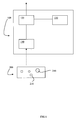
- FIG 1 shows a schematic view of modules forming part of an inspection apparatus 100 according to an embodiment of the invention.
- Inspection apparatus 100 comprises an image capture module 110, an operating system 120 and a data storage module 130.
- image capture module 110 is in the form of a digital camera or the like able to capture images of an object under inspection 200. Furthermore, image capture module 110 includes lighting and illumination devices, such as light emitting diodes or the like, to allow appropriate illumination and lighting conditions to allow the digital camera to capture an appropriate image of the object under inspection.
- lighting and illumination devices such as light emitting diodes or the like, to allow appropriate illumination and lighting conditions to allow the digital camera to capture an appropriate image of the object under inspection.
- Image capture module 110 is in communication with operating system 120 of inspection apparatus 100 and, in the embodiment, image capture module 110 communicates digital data relating to physical features of the object under inspection 200 to the operating system 120 for processing. Furthermore, operating system 120 communicates with the image capture module 120 to control the focus and magnification characteristics of the digital camera and the illumination levels and color output of the lighting and illumination devices.
- Operating system 120 is also in communication with data storage module 130.
- data storage module 130 has stored therein a parts program associated with the object under inspection.
- the parts program stored within the data storage module 120 contains an identification of the physical features 210 present on the object under inspection 200 together with a series of one or more attributes associated with each feature. These attributes include feature's geometric properties and spatial location on the object and illumination, magnification and focus settings that are required to capture the physical features 210 of the object under inspection 200.
- Operating system 120 communicates the result of the inspection of the object to a user of the inspection apparatus 100 as is known in the art.
- FIG 2 shows an inspection method 300 according to an embodiment of the invention.
- the operating system 120 identifies the current primary feature from the features 210 on the object under inspection 200 (step 310).
- the primary feature may be the first feature 210 on the object under inspection 200 in the field of view of the image capture module 110.
- the primary feature may be the first feature on the parts program stored in the data storage module 130.
- the primary feature may be the feature in the parts program that is located proximal the centre of the current field of view of the image capture module.
- the operating system 120 selects one or more additional features 210 on the object under inspection 200 based on the attributes associated with each feature 210 located in the parts program stored in the data storage module 120 (step 320) as discussed in greater detail with reference to FIG 3 .
- the operating system 120 communicates with the image capture module 110 in order that the image capture module 110 inspects the selected features (step 330). Suitably this occurs by capturing an image of the selected features for processing by the operating system 120 as will be discussed in greater detail below.
- the operating system determines whether all of the features contained in the parts list stored in the data storage module 120 have had their respective features inspected (step 340).
- the operating system 120 identifies a new primary feature and the method proceeds as previously discussed (step 310).
- the operating system prepares the results of the inspection based upon the captured images (step350). Suitably, this process occurs as is known in the art and the results of the inspection are then communicated for analysis to determine whether the object under inspection 200 has been manufactured to within a desired tolerance.
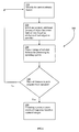
- FIG 3 shows the step of 320 in greater detail.
- the operating system 120 parses through the parts program and identifies all features that have identical environmental attributes as the current primary feature (step 321).
- environmental attributes include such attributes as illumination, magnification and focus settings.
- the operating system 120 then orders the identified features based on each feature's proximity to the current primary feature (step 322) with the closest feature to the primary feature heading the list.
- the operating system 120 uses the spatial location attribute of each feature during the ordering process.
- the operating system 120 then parses the list and selects the next most proximal feature (step 323) and determines whether that feature is able to be captured in the current field of view of the image capture module 110 (step 324). If the list has been exhausted the method continues from step 330 as previously described.
- next most proximal feature is able to be captured in the current field of view of the image capture module 110, that feature is selected for inspection (step 325).
- next most proximal feature is not able to be captured in the current field of view of the image capture module 110, that feature is discarded and returned to the parts program for later inspection (step 326).
- the method and system of the invention reduces the amount of movement of the image capture device relative to the object and the number of actual image captures is reduced. In this way, time for inspection is minimized which results in subsequent cost savings to the owner.
Landscapes
- Engineering & Computer Science (AREA)
- Computer Vision & Pattern Recognition (AREA)
- Signal Processing (AREA)
- Physics & Mathematics (AREA)
- Health & Medical Sciences (AREA)
- Life Sciences & Earth Sciences (AREA)
- Chemical & Material Sciences (AREA)
- Analytical Chemistry (AREA)
- Biochemistry (AREA)
- General Health & Medical Sciences (AREA)
- General Physics & Mathematics (AREA)
- Immunology (AREA)
- Pathology (AREA)
- Investigating Materials By The Use Of Optical Means Adapted For Particular Applications (AREA)
- Image Analysis (AREA)
Description
- The present invention relates to an inspection method and an inspection apparatus. In particular, although not exclusively, the invention relates to a method of capturing images in a measuring machine environment to thereby undertake optical quality control of objects under inspection.
- In applications where parts are required to be manufactured to a high level of precision, for example in the airline and aerospace industries, highly accurate quality control mechanisms must be in place in order to ensure that parts are manufactured to specification without divergence from the design or error. Whilst highly accurate manufacturing machines are used to manufacture parts in these industries, errors may still be present in a particular part.
- It is impractical and indeed impossible to visually inspect many of these parts by eye and obtain any degree of confidence that the part has been manufactured exactly to specification.
- Video measurement machines are used to inspect manufactured parts. These machines generally have an image capture device, such as a digital camera or the like, and data processing and storage capabilities. The part is placed within the field of view of the image capture device and the design technical specification of a manufactured object, referred to in the art as the parts program, is stored within the storage device of the measuring machine.
- A machine vision inspection system is known from
US 2004/0223053 . - The parts program includes a series of features associated with the manufactured object. Each feature in the parts program has a series of attributes associated therewith including the feature's geometric properties and spatial location on the object and illumination, magnification and focus settings to allow the measurement machine to capture a suitable image of the feature.
- When the parts program is executed, instructions are provided to the operating program of the measurement machine to control the camera and move the camera relative to the object in order to measure each of the features of the object recorded in the parts program. Typically, measurement machine operating programs move through the features recorded in the parts program sequentially and capture the features on the object independently to determine whether the object has been manufactured in accordance with the design specification without error.
- For objects that are large and/or have a large number of physical features requiring inspection and measurement, this process can be time consuming. As the measurement and inspection process is part of the manufacturing process, any reduction in the time required to perform this highly accurate quality assurance will deliver reductions in manufacturing time and hence a benefit to the manufacturer.
- In this specification, the terms "comprises", "comprising", "includes", "including" or similar terms are intended to mean a non-exclusive inclusion, such that a method, system or apparatus that comprises a list of elements does not include those elements solely, but may well include other elements not listed.
- The invention resides in a method of inspecting an object with a method according to claim 1 and an apparatus according to claim 7.
- Further features of the invention will become apparent from the following detailed description.
- By way of example only, preferred embodiments of the invention will be described more fully hereinafter with reference to the accompanying drawings, wherein:
-
FIG 1 shows a modular schematic of an inspection apparatus according to an embodiment of the invention; -
FIG 2 shows an inspection method according to an embodiment of the invention; and -
FIG 3 shows an embodiment of a method of selecting objects forming part of the method shown inFIG 2 . -
FIG 1 shows a schematic view of modules forming part of aninspection apparatus 100 according to an embodiment of the invention.Inspection apparatus 100 comprises animage capture module 110, anoperating system 120 and adata storage module 130. - In the embodiment,
image capture module 110 is in the form of a digital camera or the like able to capture images of an object underinspection 200. Furthermore,image capture module 110 includes lighting and illumination devices, such as light emitting diodes or the like, to allow appropriate illumination and lighting conditions to allow the digital camera to capture an appropriate image of the object under inspection. -
Image capture module 110 is in communication withoperating system 120 ofinspection apparatus 100 and, in the embodiment,image capture module 110 communicates digital data relating to physical features of the object underinspection 200 to theoperating system 120 for processing. Furthermore,operating system 120 communicates with theimage capture module 120 to control the focus and magnification characteristics of the digital camera and the illumination levels and color output of the lighting and illumination devices. -
Operating system 120 is also in communication withdata storage module 130. In the embodiment,data storage module 130 has stored therein a parts program associated with the object under inspection. - The parts program stored within the
data storage module 120 contains an identification of thephysical features 210 present on the object underinspection 200 together with a series of one or more attributes associated with each feature. These attributes include feature's geometric properties and spatial location on the object and illumination, magnification and focus settings that are required to capture thephysical features 210 of the object underinspection 200. -
Operating system 120 communicates the result of the inspection of the object to a user of theinspection apparatus 100 as is known in the art. -
FIG 2 shows aninspection method 300 according to an embodiment of the invention. Theoperating system 120 identifies the current primary feature from thefeatures 210 on the object under inspection 200 (step 310). Suitably, the primary feature may be thefirst feature 210 on the object underinspection 200 in the field of view of theimage capture module 110. - Optionally, the primary feature may be the first feature on the parts program stored in the
data storage module 130. Alternatively, the primary feature may be the feature in the parts program that is located proximal the centre of the current field of view of the image capture module. - The
operating system 120 then selects one or moreadditional features 210 on the object underinspection 200 based on the attributes associated with eachfeature 210 located in the parts program stored in the data storage module 120 (step 320) as discussed in greater detail with reference toFIG 3 . - Once the set of selected features has been compiled by the
operating system 120, theoperating system 120 communicates with theimage capture module 110 in order that theimage capture module 110 inspects the selected features (step 330). Suitably this occurs by capturing an image of the selected features for processing by theoperating system 120 as will be discussed in greater detail below. - The operating system then determines whether all of the features contained in the parts list stored in the
data storage module 120 have had their respective features inspected (step 340). - If all features have not been inspected, the
operating system 120 then identifies a new primary feature and the method proceeds as previously discussed (step 310). - If all features have been inspected, the operating system prepares the results of the inspection based upon the captured images (step350). Suitably, this process occurs as is known in the art and the results of the inspection are then communicated for analysis to determine whether the object under
inspection 200 has been manufactured to within a desired tolerance. -
FIG 3 shows the step of 320 in greater detail. Theoperating system 120 parses through the parts program and identifies all features that have identical environmental attributes as the current primary feature (step 321). Suitably, environmental attributes include such attributes as illumination, magnification and focus settings. - The
operating system 120 then orders the identified features based on each feature's proximity to the current primary feature (step 322) with the closest feature to the primary feature heading the list. Preferably, theoperating system 120 uses the spatial location attribute of each feature during the ordering process. - The
operating system 120 then parses the list and selects the next most proximal feature (step 323) and determines whether that feature is able to be captured in the current field of view of the image capture module 110 (step 324). If the list has been exhausted the method continues fromstep 330 as previously described. - If the next most proximal feature is able to be captured in the current field of view of the
image capture module 110, that feature is selected for inspection (step 325). - If the next most proximal feature is not able to be captured in the current field of view of the
image capture module 110, that feature is discarded and returned to the parts program for later inspection (step 326). - The method and system of the invention reduces the amount of movement of the image capture device relative to the object and the number of actual image captures is reduced. In this way, time for inspection is minimized which results in subsequent cost savings to the owner.
- Throughout the specification the aim has been to describe the present invention without limiting the invention to any one embodiment or specific collection of features. Persons skilled in the relevant art may realize variations from the specific embodiments that will nonetheless fall within the scope of the present invention.
Claims (9)
- A method of inspecting an object (200), the object (200) having a plurality of physical features (210), each of the features (210) having one or more attributes associated therewith, the attributes comprising• geometric properties of the feature (210);• spatial location of the feature (210) on the object (200); and/or• environmental attributes,
characterized in that
the method includes the steps of:• identifying a current primary feature of the object (200);• selecting one or more additional features, each of the one or more additional features selected having at least one common attribute with the current primary feature; and• capturing an image of the selected features on an image capture module (110),
wherein the step of identifying a current primary feature of the object (200) involves selecting• a first feature on a parts list stored in a data store (130) of an inspection apparatus (100) ;• a first feature in a current field of view of the image capture module (110); and/or• a feature located proximal the centre of the current field of view of the image capture module (110), and
wherein the step of selecting one or more additional features involves the steps of:• identifying all features on the object (200) that have environmental attributes identical to the environmental attributes of the current primary feature;• determining whether each of the identified features is able to be captured in a current field of view of the image capture module (110); and• selecting an identified feature if the identified feature is within the current field of view of the image capture module (110). - The method of claim 1,
characterized in that
each feature and each of the one or more attributes associated with each feature are stored in a parts list in a data store (130) of the inspection apparatus (100) - The method of claim 1 or 2,
characterized in that
an identified feature is returned to a parts list in the data store (130) of the inspection apparatus (100) and has associated therewith an indication that the identified feature has not been selected if the identified feature is not within the current field of view of the image capture module (110). - The method of claim 1, 2 or 3,
characterized in that
environmental attributes include illumination settings of the image capture module (110), magnification settings of the image capture module (110) and focus settings of the image capture module (110). - The method of any one of the preceding claims,
characterized in that
the step of determining whether each of the identified features is able to be captured in a current field of view of the image capture module (110) involves parsing, in an operating system (120) of the inspection apparatus (100), an ordered list of the identified features, whereby the ordered list is ordered on the basis of each feature's proximity to the current primary feature. - The method of any one of the preceding claims,
characterized by
further including the steps of:• determining, in an operating system (120) of the inspection apparatus (100), whether the selected features have been manufactured to within a predetermined tolerance; and• communicating whether the selected features have been manufactured to within a predetermined tolerance. - An inspection apparatus (100) comprising:• an image capture module (110) adapted to capture a digital image of at least a portion of an object (200) under inspection; and• a data store (130) having stored therein a parts list identifying a set of physical features (210) on the object (200) under inspection, each feature (210) having one or more attributes associated therewith, each attribute comprising at least geometric properties of the feature (210), spatial location of the feature (210) on the object (200) and/or environmental attributes;
characterized by
an operating system (120) containing computer readable instructions for:• identifying a current primary feature on the object (200) under inspection;• selecting one or more additional features from the parts list, each of the one or more additional features selected having at least one common attribute with the current primary feature; and• capturing an image of the selected features using the image capture module (110),
wherein identifying a current primary feature of the object (200) involves selecting• a first feature on the parts list stored in the data store (130);• a first feature in a current field of view of the image capture module (110); and/or• a feature located proximal the centre in a current field of view of the image capture module (110), and
wherein selecting one or more additional features involves the steps of:• identifying all features on the object (200) that have environmental attributes identical to the environmental attributes of the current primary feature;• determining whether each of the identified features is able to be captured in a current field of view of the image capture module (110); and• selecting an identified feature if the identified feature is within the current field of view of the image capture module (110). - The inspection apparatus (100) of claim 7,
characterized in that
the image capture module (110) is a digital camera operable under instruction from the operating system (120). - The inspection apparatus (100) of claim 7 or 8,
characterized in that
the environmental attributes include illumination settings of the image capture module (110), magnification settings of the image capture module (110) and focus settings of the image capture module (110).
Applications Claiming Priority (2)
| Application Number | Priority Date | Filing Date | Title |
|---|---|---|---|
| AU2009901899A AU2009901899A0 (en) | 2009-04-30 | An inspection method and system | |
| PCT/EP2010/055859 WO2010145881A1 (en) | 2009-04-30 | 2010-04-29 | An inspection method and an inspection apparatus |
Publications (2)
| Publication Number | Publication Date |
|---|---|
| EP2425232A1 EP2425232A1 (en) | 2012-03-07 |
| EP2425232B1 true EP2425232B1 (en) | 2013-01-09 |
Family
ID=42378914
Family Applications (1)
| Application Number | Title | Priority Date | Filing Date |
|---|---|---|---|
| EP10720376A Active EP2425232B1 (en) | 2009-04-30 | 2010-04-29 | An inspection method and an inspection apparatus |
Country Status (6)
| Country | Link |
|---|---|
| US (1) | US8781208B2 (en) |
| EP (1) | EP2425232B1 (en) |
| CN (1) | CN102378909B (en) |
| AU (1) | AU2010262034B2 (en) |
| CA (1) | CA2760377C (en) |
| WO (1) | WO2010145881A1 (en) |
Cited By (2)
| Publication number | Priority date | Publication date | Assignee | Title |
|---|---|---|---|---|
| WO2014121371A1 (en) * | 2013-02-06 | 2014-08-14 | Clearwater Seafoods Limited Partnership | Imaging for determination of crustacean physical attributes |
| WO2021061584A1 (en) * | 2019-09-27 | 2021-04-01 | Kla Corporation | Sensitive optical metrology in scanning and static modes |
Families Citing this family (3)
| Publication number | Priority date | Publication date | Assignee | Title |
|---|---|---|---|---|
| WO2016083897A2 (en) * | 2014-11-24 | 2016-06-02 | Kitov Systems Ltd. | Automated inspection |
| US10255671B1 (en) * | 2015-03-06 | 2019-04-09 | Assembly Guidance Systems, Inc. | System and method for capture of high resolution/high magnification images |
| CN107145689A (en) * | 2017-06-12 | 2017-09-08 | 郑州云海信息技术有限公司 | A Method of Checking Text Direction in PCB Design |
Family Cites Families (26)
| Publication number | Priority date | Publication date | Assignee | Title |
|---|---|---|---|---|
| DE4014661C2 (en) * | 1990-05-08 | 1996-03-28 | Groz & Soehne Theodor | Optical control of knitting needles on knitting machines |
| IL99823A0 (en) * | 1990-11-16 | 1992-08-18 | Orbot Instr Ltd | Optical inspection method and apparatus |
| US5495535A (en) * | 1992-01-31 | 1996-02-27 | Orbotech Ltd | Method of inspecting articles |
| IL123473A (en) * | 1997-02-28 | 2001-08-08 | Fiekowsky Peter J | High accuracy particle dimension measurement system |
| US7617474B2 (en) * | 1997-09-17 | 2009-11-10 | Synopsys, Inc. | System and method for providing defect printability analysis of photolithographic masks with job-based automation |
| US6175644B1 (en) * | 1998-05-01 | 2001-01-16 | Cognex Corporation | Machine vision system for object feature analysis and validation based on multiple object images |
| DE19852323C2 (en) * | 1998-11-12 | 2001-08-16 | Steag Hamatech Ag | Method for determining the thickness of layers provided on a substrate |
| JP4206192B2 (en) * | 2000-11-09 | 2009-01-07 | 株式会社日立製作所 | Pattern inspection method and apparatus |
| US6707544B1 (en) | 1999-09-07 | 2004-03-16 | Applied Materials, Inc. | Particle detection and embedded vision system to enhance substrate yield and throughput |
| JP4274649B2 (en) * | 1999-10-07 | 2009-06-10 | 株式会社日立製作所 | Fine pattern inspection method and apparatus |
| US20020085761A1 (en) * | 2000-12-30 | 2002-07-04 | Gary Cao | Enhanced uniqueness for pattern recognition |
| US20030118230A1 (en) * | 2001-12-22 | 2003-06-26 | Haoshi Song | Coiled tubing inspection system using image pattern recognition |
| US9092841B2 (en) * | 2004-06-09 | 2015-07-28 | Cognex Technology And Investment Llc | Method and apparatus for visual detection and inspection of objects |
| US7016525B2 (en) * | 2002-05-02 | 2006-03-21 | Mitutoyo Corporation | Systems and methods for continuously varying wavelength illumination |
| KR100474571B1 (en) * | 2002-09-23 | 2005-03-10 | 삼성전자주식회사 | Method of setting reference images, method and apparatus using the setting method for inspecting patterns on a wafer |
| US7027143B1 (en) * | 2002-10-15 | 2006-04-11 | Kla-Tencor Technologies Corp. | Methods and systems for inspecting reticles using aerial imaging at off-stepper wavelengths |
| JP4121849B2 (en) * | 2002-12-26 | 2008-07-23 | オリンパス株式会社 | Defect inspection apparatus and defect inspection method |
| US7508973B2 (en) * | 2003-03-28 | 2009-03-24 | Hitachi High-Technologies Corporation | Method of inspecting defects |
| US20040223053A1 (en) | 2003-05-07 | 2004-11-11 | Mitutoyo Corporation | Machine vision inspection system and method having improved operations for increased precision inspection throughput |
| DE10330006B4 (en) | 2003-07-03 | 2006-07-20 | Leica Microsystems Semiconductor Gmbh | Device for inspecting a wafer |
| US20050031191A1 (en) * | 2003-08-04 | 2005-02-10 | Mitutoyo Corporation | Methods and apparatus for inspection of lines embedded in highly textured material |
| TWI302756B (en) * | 2004-04-19 | 2008-11-01 | Phoseon Technology Inc | Imaging semiconductor structures using solid state illumination |
| US7454053B2 (en) * | 2004-10-29 | 2008-11-18 | Mitutoyo Corporation | System and method for automatically recovering video tools in a vision system |
| US20080069428A1 (en) * | 2006-08-23 | 2008-03-20 | Robert Schulkin | Single mode digital video gauging system having mechanical drawing annotations and method for same |
| JP4358889B1 (en) * | 2008-06-27 | 2009-11-04 | 日本エレクトロセンサリデバイス株式会社 | Wafer defect inspection equipment |
| SG164293A1 (en) * | 2009-01-13 | 2010-09-29 | Semiconductor Technologies & Instruments Pte | System and method for inspecting a wafer |
-
2010
- 2010-04-29 CN CN201080014535.4A patent/CN102378909B/en active Active
- 2010-04-29 EP EP10720376A patent/EP2425232B1/en active Active
- 2010-04-29 AU AU2010262034A patent/AU2010262034B2/en active Active
- 2010-04-29 US US13/318,106 patent/US8781208B2/en active Active
- 2010-04-29 WO PCT/EP2010/055859 patent/WO2010145881A1/en not_active Ceased
- 2010-04-29 CA CA2760377A patent/CA2760377C/en active Active
Cited By (7)
| Publication number | Priority date | Publication date | Assignee | Title |
|---|---|---|---|---|
| WO2014121371A1 (en) * | 2013-02-06 | 2014-08-14 | Clearwater Seafoods Limited Partnership | Imaging for determination of crustacean physical attributes |
| AU2013377779B2 (en) * | 2013-02-06 | 2017-01-05 | Clearwater Seafoods Limited Partnership | Imaging for determination of crustacean physical attributes |
| US10111411B2 (en) | 2013-02-06 | 2018-10-30 | Clearwater Seafoods Limited Partnership | Imaging for determination of crustacean physical attributes |
| US10638730B2 (en) | 2013-02-06 | 2020-05-05 | Clearwater Seafoods Limited Partnership | Imaging for determination of crustacean physical attributes |
| WO2021061584A1 (en) * | 2019-09-27 | 2021-04-01 | Kla Corporation | Sensitive optical metrology in scanning and static modes |
| EP4025903A4 (en) * | 2019-09-27 | 2023-09-27 | KLA Corporation | SENSITIVE OPTICAL METROLOGY IN SCANNING AND STATIC MODES |
| US11933717B2 (en) | 2019-09-27 | 2024-03-19 | Kla Corporation | Sensitive optical metrology in scanning and static modes |
Also Published As
| Publication number | Publication date |
|---|---|
| AU2010262034A1 (en) | 2011-09-29 |
| CA2760377A1 (en) | 2010-12-23 |
| AU2010262034B2 (en) | 2013-01-10 |
| US8781208B2 (en) | 2014-07-15 |
| CA2760377C (en) | 2016-02-23 |
| CN102378909B (en) | 2014-07-02 |
| EP2425232A1 (en) | 2012-03-07 |
| WO2010145881A1 (en) | 2010-12-23 |
| CN102378909A (en) | 2012-03-14 |
| US20120070063A1 (en) | 2012-03-22 |
Similar Documents
| Publication | Publication Date | Title |
|---|---|---|
| EP3102018B1 (en) | Quality management device and method for controlling quality management device | |
| EP2425232B1 (en) | An inspection method and an inspection apparatus | |
| US12112963B2 (en) | Defect inspection apparatus and defect inspection program | |
| JP5597056B2 (en) | Image measuring apparatus, image measuring method, and program for image measuring apparatus | |
| EP3190403B1 (en) | Measurement processing device, measurement processing method, measurement processing program, and structure production method | |
| EP1653224B1 (en) | Smear-limit based method for controlling vision systems for consistently accurate and high-speed inspection | |
| US9612210B2 (en) | Systems and methods for automatically inspecting wire segments | |
| US8937654B2 (en) | Machine vision inspection system comprising two cameras having a rotational offset | |
| US20130112893A1 (en) | Charged particle beam device, defect observation device, and management server | |
| CN109425327B (en) | Inspection system and method for correcting inspection image | |
| CN111448585A (en) | Inspection processing device, inspection processing method, and program | |
| US20230222646A1 (en) | Automated visual-inspection system | |
| CN101672630A (en) | Image measuring apparatus and computer program | |
| EP2847676B1 (en) | System and method of distributed procesing for machine-vision analysis | |
| JP2009267099A (en) | Board inspection method, and inspection result confirmation system of automatic visual inspection | |
| JP2016070683A (en) | Image processing device, image measurement device, image processing method, image processing program, and method for manufacturing structure | |
| CN109955220A (en) | Robot system | |
| US12190543B2 (en) | Lens calibration method for digital imaging apparatus | |
| JP6170140B2 (en) | Substrate visual inspection device | |
| CN113269736A (en) | Method, system and medium for automated inspection of fastener dimensions | |
| US20220036529A1 (en) | Device and method for the calibrated checking of a printing on an article | |
| US20240303982A1 (en) | Image processing device and image processing method | |
| JP2023051102A (en) | Image inspection method and image inspection apparatus | |
| WO2016067423A1 (en) | Image measurement device, structure manufacturing method, image measurement method, and image measurement program |
Legal Events
| Date | Code | Title | Description |
|---|---|---|---|
| PUAI | Public reference made under article 153(3) epc to a published international application that has entered the european phase |
Free format text: ORIGINAL CODE: 0009012 |
|
| 17P | Request for examination filed |
Effective date: 20111129 |
|
| AK | Designated contracting states |
Kind code of ref document: A1 Designated state(s): AT BE BG CH CY CZ DE DK EE ES FI FR GB GR HR HU IE IS IT LI LT LU LV MC MK MT NL NO PL PT RO SE SI SK SM TR |
|
| DAX | Request for extension of the european patent (deleted) | ||
| GRAP | Despatch of communication of intention to grant a patent |
Free format text: ORIGINAL CODE: EPIDOSNIGR1 |
|
| GRAS | Grant fee paid |
Free format text: ORIGINAL CODE: EPIDOSNIGR3 |
|
| GRAA | (expected) grant |
Free format text: ORIGINAL CODE: 0009210 |
|
| AK | Designated contracting states |
Kind code of ref document: B1 Designated state(s): AT BE BG CH CY CZ DE DK EE ES FI FR GB GR HR HU IE IS IT LI LT LU LV MC MK MT NL NO PL PT RO SE SI SK SM TR |
|
| REG | Reference to a national code |
Ref country code: GB Ref legal event code: FG4D |
|
| REG | Reference to a national code |
Ref country code: CH Ref legal event code: EP Ref country code: AT Ref legal event code: REF Ref document number: 593020 Country of ref document: AT Kind code of ref document: T Effective date: 20130115 |
|
| REG | Reference to a national code |
Ref country code: IE Ref legal event code: FG4D |
|
| REG | Reference to a national code |
Ref country code: DE Ref legal event code: R096 Ref document number: 602010004553 Country of ref document: DE Effective date: 20130307 |
|
| REG | Reference to a national code |
Ref country code: SE Ref legal event code: TRGR |
|
| REG | Reference to a national code |
Ref country code: NL Ref legal event code: T3 |
|
| PG25 | Lapsed in a contracting state [announced via postgrant information from national office to epo] |
Ref country code: SI Free format text: LAPSE BECAUSE OF FAILURE TO SUBMIT A TRANSLATION OF THE DESCRIPTION OR TO PAY THE FEE WITHIN THE PRESCRIBED TIME-LIMIT Effective date: 20130109 |
|
| REG | Reference to a national code |
Ref country code: AT Ref legal event code: MK05 Ref document number: 593020 Country of ref document: AT Kind code of ref document: T Effective date: 20130109 |
|
| REG | Reference to a national code |
Ref country code: LT Ref legal event code: MG4D |
|
| PG25 | Lapsed in a contracting state [announced via postgrant information from national office to epo] |
Ref country code: NO Free format text: LAPSE BECAUSE OF FAILURE TO SUBMIT A TRANSLATION OF THE DESCRIPTION OR TO PAY THE FEE WITHIN THE PRESCRIBED TIME-LIMIT Effective date: 20130409 Ref country code: BE Free format text: LAPSE BECAUSE OF FAILURE TO SUBMIT A TRANSLATION OF THE DESCRIPTION OR TO PAY THE FEE WITHIN THE PRESCRIBED TIME-LIMIT Effective date: 20130109 Ref country code: IS Free format text: LAPSE BECAUSE OF FAILURE TO SUBMIT A TRANSLATION OF THE DESCRIPTION OR TO PAY THE FEE WITHIN THE PRESCRIBED TIME-LIMIT Effective date: 20130509 Ref country code: AT Free format text: LAPSE BECAUSE OF FAILURE TO SUBMIT A TRANSLATION OF THE DESCRIPTION OR TO PAY THE FEE WITHIN THE PRESCRIBED TIME-LIMIT Effective date: 20130109 Ref country code: LT Free format text: LAPSE BECAUSE OF FAILURE TO SUBMIT A TRANSLATION OF THE DESCRIPTION OR TO PAY THE FEE WITHIN THE PRESCRIBED TIME-LIMIT Effective date: 20130109 Ref country code: BG Free format text: LAPSE BECAUSE OF FAILURE TO SUBMIT A TRANSLATION OF THE DESCRIPTION OR TO PAY THE FEE WITHIN THE PRESCRIBED TIME-LIMIT Effective date: 20130409 Ref country code: ES Free format text: LAPSE BECAUSE OF FAILURE TO SUBMIT A TRANSLATION OF THE DESCRIPTION OR TO PAY THE FEE WITHIN THE PRESCRIBED TIME-LIMIT Effective date: 20130420 |
|
| PG25 | Lapsed in a contracting state [announced via postgrant information from national office to epo] |
Ref country code: PT Free format text: LAPSE BECAUSE OF FAILURE TO SUBMIT A TRANSLATION OF THE DESCRIPTION OR TO PAY THE FEE WITHIN THE PRESCRIBED TIME-LIMIT Effective date: 20130509 Ref country code: LV Free format text: LAPSE BECAUSE OF FAILURE TO SUBMIT A TRANSLATION OF THE DESCRIPTION OR TO PAY THE FEE WITHIN THE PRESCRIBED TIME-LIMIT Effective date: 20130109 Ref country code: GR Free format text: LAPSE BECAUSE OF FAILURE TO SUBMIT A TRANSLATION OF THE DESCRIPTION OR TO PAY THE FEE WITHIN THE PRESCRIBED TIME-LIMIT Effective date: 20130410 Ref country code: PL Free format text: LAPSE BECAUSE OF FAILURE TO SUBMIT A TRANSLATION OF THE DESCRIPTION OR TO PAY THE FEE WITHIN THE PRESCRIBED TIME-LIMIT Effective date: 20130109 Ref country code: FI Free format text: LAPSE BECAUSE OF FAILURE TO SUBMIT A TRANSLATION OF THE DESCRIPTION OR TO PAY THE FEE WITHIN THE PRESCRIBED TIME-LIMIT Effective date: 20130109 |
|
| PG25 | Lapsed in a contracting state [announced via postgrant information from national office to epo] |
Ref country code: HR Free format text: LAPSE BECAUSE OF FAILURE TO SUBMIT A TRANSLATION OF THE DESCRIPTION OR TO PAY THE FEE WITHIN THE PRESCRIBED TIME-LIMIT Effective date: 20130109 |
|
| PG25 | Lapsed in a contracting state [announced via postgrant information from national office to epo] |
Ref country code: EE Free format text: LAPSE BECAUSE OF FAILURE TO SUBMIT A TRANSLATION OF THE DESCRIPTION OR TO PAY THE FEE WITHIN THE PRESCRIBED TIME-LIMIT Effective date: 20130109 Ref country code: RO Free format text: LAPSE BECAUSE OF FAILURE TO SUBMIT A TRANSLATION OF THE DESCRIPTION OR TO PAY THE FEE WITHIN THE PRESCRIBED TIME-LIMIT Effective date: 20130109 Ref country code: SK Free format text: LAPSE BECAUSE OF FAILURE TO SUBMIT A TRANSLATION OF THE DESCRIPTION OR TO PAY THE FEE WITHIN THE PRESCRIBED TIME-LIMIT Effective date: 20130109 Ref country code: CZ Free format text: LAPSE BECAUSE OF FAILURE TO SUBMIT A TRANSLATION OF THE DESCRIPTION OR TO PAY THE FEE WITHIN THE PRESCRIBED TIME-LIMIT Effective date: 20130109 Ref country code: DK Free format text: LAPSE BECAUSE OF FAILURE TO SUBMIT A TRANSLATION OF THE DESCRIPTION OR TO PAY THE FEE WITHIN THE PRESCRIBED TIME-LIMIT Effective date: 20130109 |
|
| PLBE | No opposition filed within time limit |
Free format text: ORIGINAL CODE: 0009261 |
|
| STAA | Information on the status of an ep patent application or granted ep patent |
Free format text: STATUS: NO OPPOSITION FILED WITHIN TIME LIMIT |
|
| PG25 | Lapsed in a contracting state [announced via postgrant information from national office to epo] |
Ref country code: MC Free format text: LAPSE BECAUSE OF FAILURE TO SUBMIT A TRANSLATION OF THE DESCRIPTION OR TO PAY THE FEE WITHIN THE PRESCRIBED TIME-LIMIT Effective date: 20130109 Ref country code: CY Free format text: LAPSE BECAUSE OF FAILURE TO SUBMIT A TRANSLATION OF THE DESCRIPTION OR TO PAY THE FEE WITHIN THE PRESCRIBED TIME-LIMIT Effective date: 20130109 |
|
| 26N | No opposition filed |
Effective date: 20131010 |
|
| PG25 | Lapsed in a contracting state [announced via postgrant information from national office to epo] |
Ref country code: IT Free format text: LAPSE BECAUSE OF FAILURE TO SUBMIT A TRANSLATION OF THE DESCRIPTION OR TO PAY THE FEE WITHIN THE PRESCRIBED TIME-LIMIT Effective date: 20130109 |
|
| REG | Reference to a national code |
Ref country code: IE Ref legal event code: MM4A |
|
| REG | Reference to a national code |
Ref country code: DE Ref legal event code: R097 Ref document number: 602010004553 Country of ref document: DE Effective date: 20131010 |
|
| PG25 | Lapsed in a contracting state [announced via postgrant information from national office to epo] |
Ref country code: IE Free format text: LAPSE BECAUSE OF NON-PAYMENT OF DUE FEES Effective date: 20130429 |
|
| PG25 | Lapsed in a contracting state [announced via postgrant information from national office to epo] |
Ref country code: MT Free format text: LAPSE BECAUSE OF FAILURE TO SUBMIT A TRANSLATION OF THE DESCRIPTION OR TO PAY THE FEE WITHIN THE PRESCRIBED TIME-LIMIT Effective date: 20130109 |
|
| REG | Reference to a national code |
Ref country code: FR Ref legal event code: PLFP Year of fee payment: 6 |
|
| PG25 | Lapsed in a contracting state [announced via postgrant information from national office to epo] |
Ref country code: SM Free format text: LAPSE BECAUSE OF FAILURE TO SUBMIT A TRANSLATION OF THE DESCRIPTION OR TO PAY THE FEE WITHIN THE PRESCRIBED TIME-LIMIT Effective date: 20130109 |
|
| PG25 | Lapsed in a contracting state [announced via postgrant information from national office to epo] |
Ref country code: TR Free format text: LAPSE BECAUSE OF FAILURE TO SUBMIT A TRANSLATION OF THE DESCRIPTION OR TO PAY THE FEE WITHIN THE PRESCRIBED TIME-LIMIT Effective date: 20130109 |
|
| PG25 | Lapsed in a contracting state [announced via postgrant information from national office to epo] |
Ref country code: LU Free format text: LAPSE BECAUSE OF NON-PAYMENT OF DUE FEES Effective date: 20130429 Ref country code: MK Free format text: LAPSE BECAUSE OF FAILURE TO SUBMIT A TRANSLATION OF THE DESCRIPTION OR TO PAY THE FEE WITHIN THE PRESCRIBED TIME-LIMIT Effective date: 20130109 Ref country code: HU Free format text: LAPSE BECAUSE OF FAILURE TO SUBMIT A TRANSLATION OF THE DESCRIPTION OR TO PAY THE FEE WITHIN THE PRESCRIBED TIME-LIMIT; INVALID AB INITIO Effective date: 20100429 |
|
| REG | Reference to a national code |
Ref country code: CH Ref legal event code: PUE Owner name: HEXAGON TECHNOLOGY CENTER GMBH, CH Free format text: FORMER OWNER: WILCOX ASSOCIATES, INC., GB Ref country code: CH Ref legal event code: NV Representative=s name: KAMINSKI HARMANN PATENTANWAELTE AG, LI |
|
| REG | Reference to a national code |
Ref country code: FR Ref legal event code: PLFP Year of fee payment: 7 |
|
| REG | Reference to a national code |
Ref country code: FR Ref legal event code: TP Owner name: HEXAGON TECHNOLOGY CENTER GMBH, CH Effective date: 20160322 |
|
| REG | Reference to a national code |
Ref country code: GB Ref legal event code: 732E Free format text: REGISTERED BETWEEN 20160728 AND 20160803 |
|
| REG | Reference to a national code |
Ref country code: DE Ref legal event code: R082 Ref document number: 602010004553 Country of ref document: DE Representative=s name: KAMINSKI HARMANN PATENTANWAELTE AG, LI Ref country code: DE Ref legal event code: R081 Ref document number: 602010004553 Country of ref document: DE Owner name: HEXAGON TECHNOLOGY CENTER GMBH, CH Free format text: FORMER OWNER: WILCOX ASSOCIATES, INC., TELFORD, GB |
|
| REG | Reference to a national code |
Ref country code: NL Ref legal event code: PD Owner name: HEXAGON TECHNOLOGY CENTER GMBH; CH Free format text: DETAILS ASSIGNMENT: CHANGE OF OWNER(S), ASSIGNMENT; FORMER OWNER NAME: WILCOX ASSOCIATES, INC. Effective date: 20161114 |
|
| REG | Reference to a national code |
Ref country code: FR Ref legal event code: PLFP Year of fee payment: 8 |
|
| REG | Reference to a national code |
Ref country code: FR Ref legal event code: PLFP Year of fee payment: 9 |
|
| PGFP | Annual fee paid to national office [announced via postgrant information from national office to epo] |
Ref country code: NL Payment date: 20250418 Year of fee payment: 16 |
|
| PGFP | Annual fee paid to national office [announced via postgrant information from national office to epo] |
Ref country code: DE Payment date: 20250422 Year of fee payment: 16 |
|
| PGFP | Annual fee paid to national office [announced via postgrant information from national office to epo] |
Ref country code: GB Payment date: 20250423 Year of fee payment: 16 |
|
| PGFP | Annual fee paid to national office [announced via postgrant information from national office to epo] |
Ref country code: FR Payment date: 20250425 Year of fee payment: 16 |
|
| PGFP | Annual fee paid to national office [announced via postgrant information from national office to epo] |
Ref country code: CH Payment date: 20250501 Year of fee payment: 16 |
|
| PGFP | Annual fee paid to national office [announced via postgrant information from national office to epo] |
Ref country code: SE Payment date: 20250429 Year of fee payment: 16 |
|
| REG | Reference to a national code |
Ref country code: CH Ref legal event code: R14 Free format text: ST27 STATUS EVENT CODE: U-0-0-R10-R14 (AS PROVIDED BY THE NATIONAL OFFICE) Effective date: 20251216 Ref country code: CH Ref legal event code: R17 Free format text: ST27 STATUS EVENT CODE: U-0-0-R10-R17 (AS PROVIDED BY THE NATIONAL OFFICE) Effective date: 20251216 |
|
| REG | Reference to a national code |
Ref country code: NL Ref legal event code: PD Owner name: HEXAGON INNOVATION HUB GMBH; CH Free format text: DETAILS ASSIGNMENT: CHANGE OF OWNER(S), ASSIGNMENT; FORMER OWNER NAME: WILCOX ASSOCIATES, INC. Effective date: 20251210 |
|
| REG | Reference to a national code |
Ref country code: DE Ref legal event code: R081 Ref document number: 602010004553 Country of ref document: DE Owner name: HEXAGON INNOVATION HUB GMBH, CH Free format text: FORMER OWNER: HEXAGON TECHNOLOGY CENTER GMBH, HEERBRUGG, CH |