EP2425221B1 - Verfahren und system zur messung der ausbreitungseigenschaften eines lichtstrahls - Google Patents
Verfahren und system zur messung der ausbreitungseigenschaften eines lichtstrahls Download PDFInfo
- Publication number
- EP2425221B1 EP2425221B1 EP10718255.2A EP10718255A EP2425221B1 EP 2425221 B1 EP2425221 B1 EP 2425221B1 EP 10718255 A EP10718255 A EP 10718255A EP 2425221 B1 EP2425221 B1 EP 2425221B1
- Authority
- EP
- European Patent Office
- Prior art keywords
- lens
- light beam
- sensor
- waist
- light
- Prior art date
- Legal status (The legal status is an assumption and is not a legal conclusion. Google has not performed a legal analysis and makes no representation as to the accuracy of the status listed.)
- Not-in-force
Links
- 238000000034 method Methods 0.000 title claims description 30
- 239000007788 liquid Substances 0.000 claims description 36
- 239000004973 liquid crystal related substance Substances 0.000 claims description 13
- 229910004613 CdTe Inorganic materials 0.000 claims description 3
- 229910000530 Gallium indium arsenide Inorganic materials 0.000 claims description 3
- XUIMIQQOPSSXEZ-UHFFFAOYSA-N Silicon Chemical group [Si] XUIMIQQOPSSXEZ-UHFFFAOYSA-N 0.000 claims description 3
- 229910052710 silicon Inorganic materials 0.000 claims description 3
- 239000010703 silicon Substances 0.000 claims description 3
- 238000005259 measurement Methods 0.000 description 33
- 230000003287 optical effect Effects 0.000 description 11
- 230000008859 change Effects 0.000 description 10
- 238000009826 distribution Methods 0.000 description 5
- 230000000694 effects Effects 0.000 description 4
- 238000004458 analytical method Methods 0.000 description 3
- 239000011521 glass Substances 0.000 description 3
- 238000003384 imaging method Methods 0.000 description 3
- 239000000463 material Substances 0.000 description 3
- 238000000691 measurement method Methods 0.000 description 3
- 230000007246 mechanism Effects 0.000 description 3
- 238000011160 research Methods 0.000 description 3
- 230000003595 spectral effect Effects 0.000 description 3
- 238000003491 array Methods 0.000 description 2
- 230000008901 benefit Effects 0.000 description 2
- 238000007796 conventional method Methods 0.000 description 2
- 230000001419 dependent effect Effects 0.000 description 2
- 238000001514 detection method Methods 0.000 description 2
- 239000012528 membrane Substances 0.000 description 2
- 239000002184 metal Substances 0.000 description 2
- 238000004377 microelectronic Methods 0.000 description 2
- 230000008569 process Effects 0.000 description 2
- 238000005086 pumping Methods 0.000 description 2
- 230000004044 response Effects 0.000 description 2
- 238000010998 test method Methods 0.000 description 2
- 229910001218 Gallium arsenide Inorganic materials 0.000 description 1
- 229910012463 LiTaO3 Inorganic materials 0.000 description 1
- 230000003044 adaptive effect Effects 0.000 description 1
- 230000004075 alteration Effects 0.000 description 1
- 230000007812 deficiency Effects 0.000 description 1
- 238000009795 derivation Methods 0.000 description 1
- 238000010586 diagram Methods 0.000 description 1
- 238000005553 drilling Methods 0.000 description 1
- 238000005516 engineering process Methods 0.000 description 1
- 238000002474 experimental method Methods 0.000 description 1
- 238000001914 filtration Methods 0.000 description 1
- 239000012530 fluid Substances 0.000 description 1
- 230000008676 import Effects 0.000 description 1
- 238000004519 manufacturing process Methods 0.000 description 1
- 239000011159 matrix material Substances 0.000 description 1
- 238000012544 monitoring process Methods 0.000 description 1
- 230000007935 neutral effect Effects 0.000 description 1
- 238000012634 optical imaging Methods 0.000 description 1
- 229920000642 polymer Polymers 0.000 description 1
- 229920005597 polymer membrane Polymers 0.000 description 1
- 230000035755 proliferation Effects 0.000 description 1
- 230000001902 propagating effect Effects 0.000 description 1
- 230000005855 radiation Effects 0.000 description 1
- 238000005070 sampling Methods 0.000 description 1
- 239000007787 solid Substances 0.000 description 1
- 229910001220 stainless steel Inorganic materials 0.000 description 1
- 239000010935 stainless steel Substances 0.000 description 1
- 238000012360 testing method Methods 0.000 description 1
Images


Classifications
-
- G—PHYSICS
- G01—MEASURING; TESTING
- G01J—MEASUREMENT OF INTENSITY, VELOCITY, SPECTRAL CONTENT, POLARISATION, PHASE OR PULSE CHARACTERISTICS OF INFRARED, VISIBLE OR ULTRAVIOLET LIGHT; COLORIMETRY; RADIATION PYROMETRY
- G01J1/00—Photometry, e.g. photographic exposure meter
- G01J1/42—Photometry, e.g. photographic exposure meter using electric radiation detectors
- G01J1/4257—Photometry, e.g. photographic exposure meter using electric radiation detectors applied to monitoring the characteristics of a beam, e.g. laser beam, headlamp beam
-
- G—PHYSICS
- G01—MEASURING; TESTING
- G01J—MEASUREMENT OF INTENSITY, VELOCITY, SPECTRAL CONTENT, POLARISATION, PHASE OR PULSE CHARACTERISTICS OF INFRARED, VISIBLE OR ULTRAVIOLET LIGHT; COLORIMETRY; RADIATION PYROMETRY
- G01J1/00—Photometry, e.g. photographic exposure meter
- G01J1/42—Photometry, e.g. photographic exposure meter using electric radiation detectors
- G01J1/4228—Photometry, e.g. photographic exposure meter using electric radiation detectors arrangements with two or more detectors, e.g. for sensitivity compensation
-
- G—PHYSICS
- G01—MEASURING; TESTING
- G01J—MEASUREMENT OF INTENSITY, VELOCITY, SPECTRAL CONTENT, POLARISATION, PHASE OR PULSE CHARACTERISTICS OF INFRARED, VISIBLE OR ULTRAVIOLET LIGHT; COLORIMETRY; RADIATION PYROMETRY
- G01J9/00—Measuring optical phase difference; Determining degree of coherence; Measuring optical wavelength
-
- G—PHYSICS
- G01—MEASURING; TESTING
- G01M—TESTING STATIC OR DYNAMIC BALANCE OF MACHINES OR STRUCTURES; TESTING OF STRUCTURES OR APPARATUS, NOT OTHERWISE PROVIDED FOR
- G01M11/00—Testing of optical apparatus; Testing structures by optical methods not otherwise provided for
- G01M11/02—Testing optical properties
- G01M11/06—Testing the alignment of vehicle headlight devices
- G01M11/061—Details of the mechanical construction of the light measuring system
Definitions
- the present invention relates to a method and apparatus for measuring the propagation properties of a light beam, for instance a collimated beam such as a laser beam.
- the propagation factor of a beam quantifies the performance of the laser beam. This allows effective prediction of the parameters of an optical system and is becoming increasingly important for various technical and commercial applications which require increasingly precise knowledge of the characteristics of a light beam. For instance, in scientific experiments it is increasingly required to focus the beam to a very high intensity for non-linear processes. In a number of industrial processes, the beam must be focused to the smallest possible spot, for applications such as drilling holes in stainless steel, for medical applications which make use of a laser beam, such as medical procedures in the eye and so on.
- M 2 beam propagation factor
- the International Organisation for Standardisation (ISO; Geneva, Switzerland) has defined a methodology standard which provides for reliable measurement of M 2 so that this parameter can be used with confidence by anyone making the measurement.
- the method involves placing a lens of a known focal length in a laser beam and then making a series of measurements through the focus waist of the beam.
- Measurements which are generally considered essential include determining the width of the spot at the smallest focus, position of the spot of that focus, the width of the beam and the focal length of the lens and the divergence of the beam beyond that point of focus.
- the width of the beam at the focal length of the lens may not be at the same place as the smallest spot.
- the measurement standard involves taking a series of measurements along different positions of the beam and then performing a curve fit to the measured data to calculate the M 2 parameters from that curve fit.
- the ISO standard specifies certain steps required to obtaining a reliable and consistent measurement of M 2 . According to this method, the lens must be held stationary and a sensor moved through the waist of the beam, although in some cases it may be easier to hold the sensor stationary and move the lens.
- Movement of the lens can provide an accurate measurement as long as the input beam is well collimated over the distance in which the lens is moved. If the beam diverges or converges over that length of travel of the lens, the M 2 measurement can be incorrect and misleading.
- the ISO standard also requires the width of the laser beam to be measured by what is known as the "Second Moment method".
- the method and associated apparatus have a number of disadvantages.
- the system requires that a series of measurements be taken and then for those measurements to be interpolated, such that in general it is only possible to obtain an estimate of the position of the waist and of its parameters.
- the system is relatively slow as a result of the need to move the sensor array or lens between measurements and also to ensure that the movement is accurate, reliable and repeatable. This does not provide the ability to determine quickly the performance characteristics of a laser beam, for example.
- such systems are also dependent upon the precision of movement of the sensor array or lens.
- the present invention seeks to provide an improved method and apparatus for determining the characteristics of a light beam, in particular of a laser beam.
- a system for obtaining a propagation factor for determining the performance of a light beam including a light sensor, a lens element operable to focus a beam from a light source to be tested towards the sensor element, the light sensor and lens element being substantially fixed in position relative to one another; wherein the lens element is a variable focus lens, the lens being adjustable so as to adjust the focal length thereof to provide to the light sensor a varying focused light beam at and either side of a waist thereof, thereby to allow the determination of a beam waist and propagation factor of the light beam and therefrom the performance of the light beam.
- Such a system does not require movement of the sensor relative to the lens, as specified in the ISO standard, or movement of the lens relative to the sensor.
- the lens and sensor can be positionally fixed relative to one another, there is no reliability issue involved with moving these components relative to one another, as in the accepted apparatus, or to provide complex motion mechanisms for moving one of these components of the system.
- variable focus lens element is adjustable by means of an electrical stimulus. This provides a most efficient way of adjusting the characteristics of the lens and therefore its focal distance, by means of a readily producible and reliable electrical stimulus signal.
- Such a lens may be an electrowetting liquid lens, for example of the type disclosed in WO-99/18456 .
- Such a lens makes use of two non-miscible liquids held in separate layers within a conducting metal cone or other chamber.
- the liquid-to-liquid interface of the two non-miscible liquids changes its curvature due to electrowetting, in effect where the relative wettability of the two liquids changes in accordance with the application of a voltage potential across the lens.
- the walls are coated with a material which repels one liquid but not the other. This causes the interface of the two liquids to form a curve proximate the centre of the lens.
- Application of voltage causes the wettability of the conducting liquid to change and thus to deform the liquid-to-liquid interface between the two non-miscible liquids, resulting in a change in the focal length of the lens.
- the lens may be a liquid crystal lens. In yet another embodiment, the lens may be a pressure controlled fluidic lens or an electro-optic variable focus lens.
- the sensor element is a CCD array.
- a single element detector such as a silicon photodiode, or an InGaAs, pyroelectric or CdTe detector element.
- the focused beam is directed to the single sensor element by a selection/directing device, which may be a motorised iris or a moveable mirror array, for instance.
- a method of determining the characteristics of a light beam including the steps of providing a sensor element, providing a variable focus lens element, the sensor element and this element being substantially fixed in position relative to one another, directing a beam to be quantified at the lens element, during a measuring step varying the focus of the lens element to provide to the sensor element a varying focused light beam at and either side of a waist of the light beam, obtaining therefrom the beam waist and the propagation factor of the light beam and determining from said obtaining step the performance of the light beam.
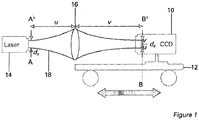
- FIG 1 is a schematic diagram of the measurement method for the determination of the beam propagation ratio and other beam characteristics of lasers.
- a CCD diode array camera system 10 is placed on a movable carriage 12 in front of a laser source 14.
- a relay lens 16 of the camera system 10 allows the CCD to capture a spatial intensity profile of the beam 18 at a particular plane.
- the beam width is then calculated using a modified second moment technique.
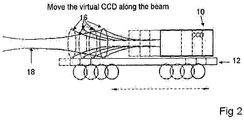
- a self-converging width measurement technique can be used to estimate the beam width at each measurement plane and represent the true value to an acceptable level of uncertainty. This measurement is repeated at a number of locations along the test beam axis, as shown schematically in Figure 2 , until enough data points have been obtained to allow the fitting of a hyperbola using a least squares fitting technique or other suitable mathematical technique.
- Figure 2 shows a series of examples of beam profile for a laser, at different positions, through the lens.
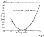
- the beam width is plotted against the position of the lens and a hyperbola fit applied to the data points.
- the coefficients of the fit are extracted. This is shown in the graph of Figure 3 . It will be appreciated that, in dependence on the components used and how these are set up, the electronic and optical components of the system might create an offset in the measurements, which can be accounted for by conventional methods.
- the coefficients of the fitted hyperbola allow the beam propagation parameters of the source to be determined.
- a convex lens 16 with minimal aberrations can create an artificial waist. This situation may arise if, for example, the beam waist is formed within the laser 14 or there is insufficient space to perform the required number of measurements either side of the waist. The position and diameter of this artificial waist can then be used, along with the known properties of the transform lens 16, to calculate the location and size of the original beam waist.
- the apparatus is provided with a support frame or device 20 upon which a laser source 14 to be tested can be accurately positioned.
- the sensor device 10 is provided on a moveable carriage 22 which can be moved by means of a stepper motor 24 attached to the framework 20.
- the stepper motor 24 enables the carriage 22 to move along the framework 20 in the direction of the two arrows shown in Figure 5 .
- This enables the sensor array to be moved along the light beam 18 in order to detect different parts of that light beam and in particular to seek to identify and measure the artificial beam waist 26 produced by the focusing lens 16.
- the camera system 10 is provided with one or more neutral density filters 28 for filtering the light beam 18 prior to the passage of this into the camera unit 10 and thus to the CCD sensor array.
- the embodiments of the present invention described below avoid the need of the use of fixed lenses and large motorised movement stages along the direction of light propagation and set the position of the lens or lenses with respect to the sensor device so that the relative positions of these two remain substantially fixed.
- the apparatus eliminates the need for movement stages and thus considerably reduces the size, complexity and cost of the apparatus.
- the method also allows simple assessment of the parameters of the system and thus can develop a system which requires less skill and expertise from the operator.
- the embodiments described below are particularly useful in the assessment and calibration of high accuracy light systems, particularly laser-based systems for use in industry, biomedicine and research, where the beam propagation parameters of the light beam must be assessed very accurately. These parameters facilitate the optimisation and continuous monitoring required for these applications to ensure maximum yields and high quality products. The parameters are also important in being able to establish the hazard potential of a laser, such as the nominal optical hazard distance and apparent source size for extended beams.
- a potential use of such a system is in the measurement of beam parameters of artificial optical sources, for example as is required by the European Artificial Optical Radiation Directive.
- the embodiments described below provide a lens and detector which are no longer translated (moved) to obtain different beam diameter measurements at different points along the beam propagation envelope.
- a variable focus lens element is used to transform the beam to allow scanning of the beam diameter to determine variations thereof, at enough sampling points so as to provide a high quality derivation of the beam propagation parameters for the light beam.
- Providing a variable focus lens element gives the apparatus greater reliability and makes it more simple, as well as reducing the power consumption of the apparatus. Of course, such apparatus represents a deviation from the requirements of ISO 11146 but it has been found can provide a more reliable and a more efficient assessment method.
- a sensor array 10 which in this example is a conventional CCD sensor array, and a variable focus liquid lens 30.
- the liquid lens has a structure of the type disclosed in WO-99/18456 , for example, and which can be described as an electrowetting liquid lens.
- the lens 30 is provided with a chamber having located therewithin a conducting metal cone and two immiscible liquids held as separate layers within the chamber. The walls of the cone are coated with a material which repels one of the liquids but not the other. This causes the liquid-to-liquid interface of the two liquids to form a curve towards the centre of the lens, that curvature of which is dependent upon the wettability of the immiscible liquids.
- FIG. 6 there are shown in schematic form the outlines of two light beams emanating from the lens 30 as a result in the change in focal length of the lens, itself caused by a change in the voltage applied to the lens.
- the lens 30 produces a highly waisted light beam which in turn generates a relatively wide beam at the CCD sensor array 10.
- the lens 30 is less curved, resulting in the light beam beyond the lens 30 being more "stretched” with the result that the waist 32 of that light beam moving closer to the position of the CCD sensor array 10 and thus in a beam of smaller width.
- This change in focus of the lens provides for beam propagation parameter measurement as M 2 , although beam propagation parameters are not necessarily restricted to just measurement of the beam quality factor (M 2 ).
- Figure 7 shows a perspective view in schematic form of the arrangement of Figure 6 with a light source 14 provided to direct a light beam 18 onto the liquid lens 30, which in turn generates the focused light beam 34 with its artificial waist 32.
- the light beam 34 has a different spread across the CCD array 10 with the result that, upon refocusing of the liquid lens 30, the focussed beam 34 can be adjusted so as to produce an artificial waist 32 which will in effect move in position from the liquid lens 30 and through the path of the CCD array 10, thus to provide a variety of measurements at the CCD array 10 in order to allow for the accurate location and determination of that waist 32.
- FIG 8 shows in schematic form another embodiment, which includes a CCD sensor array 10 as previously described and a liquid crystal Fresnel lens 36.
- Such lenses are well known in the art. Briefly, such lenses include liquid crystal located between two flat pieces of glass and concentric electrodes located and used for controlling the state of the liquid crystal material between the glass panels. The liquid crystal is controlled by applying a low voltage across the electrodes. Switching on the voltage for a particular electrode alters the effective refractive index of that part of the lens. By turning the concentric electrodes on or off, the focussing power of the lens can be changed from substantially zero to a few dioptres. Liquid crystal lenses of this type can operate in temperatures between -10°C and +50°C.
- the focal length of the lens 36 can be varied, thus varying the shape of the beam passing through the lens 36 and thus moving the effective waist 32 which is produced by this beam, thereby to project onto the CCD array 10 different portions of the beam 34 and thus with the purpose of identifying the location and dimensions of the artificial waist 32.
- This embodiment will operate in an analogous manner to the liquid lens of the embodiment of Figures 4 and 5 .
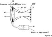
- the lens may be of a type which consists of a flexible membrane 40 containing a transparent liquid 42. Coupled to the lens 38 is a liquid or gas reservoir 44 and a pumping mechanism for pumping fluid pressure into and out of the liquid lens 38. Inflation of the lens 38 increases the curvature of the transparent flexible membrane 40, which thereby changes the refraction characteristics of the lens. In this manner, the focal length of the lens 38 can be altered so as to generate a varying beam 34 with a moveable artificial waist 32, in a similar manner to the embodiments to Figures 6 to 8 above.
- a variety of pressure controlled fluidic lenses are known in the art in addition to the example shown in Figure 9 .
- Holochip Corporation and Albuquerque, USA manufactures what it describes as an adaptive polymer lens, which operates by forming a lens from a liquid sealed in the transparent polymer membrane. The application of horizontal pressure to the circumference of the lens varies its focal length.
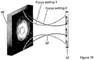
- Figure 10 shows another embodiment which makes use of an electro-optic variable focus lens 46 able to generate a tunable optical power range, typically between around -129 to +129 dioptres.
- a lens can be achieved by using a combination of two cylindrical electro-optic ferroelectric domain lens stacks in an orthogonal geometry, as described for example by Mahesh Krishnamurthi and colleagues in Applied Physics Letters, Volume 90, Issue 20, id. 201106 (2007 ) in the article entitled " Two Dimensional Dynamic Focusing of Laser Light by Ferroelectric Domain Based Electro-Optic Lenses"; and by M. J.
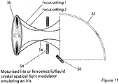
- FIG. 11 and 12 show the embodiments of apparatus which make use of a single sensor element. This avoids the need for an array detector of the type described above.
- Array detectors are expensive compared to single element detectors and do not have the same dynamic range and linearity characteristics of most discrete devices. Infra-red array detectors are high cost low resolution devices and are often subject to import controls due to their military applications.
- FIG 11 there is shown an example of apparatus which uses a single element detector 50 in place of a CCD array 10 of the type shown in the previously described embodiments.
- a liquid lens 30 is shown, although any of the lenses described above could be used in its place.
- the detector element 50 of Figure 11 could be any suitable high accuracy photodetector, such as a silicon photodiode, an InGaAs, pyroelectric or CdTe photodetector device.
- the light beam 34 from the lens 30 is reflected onto the detector 50 by means of a concave diffuser or mirror 52 of suitable form, that is which is able to reflect light coming from the lens 30 onto the single element detector 50.
- the apparatus includes an adaptable iris element 54 located between the lens 30 and the diffuser or mirror 52 which is designed and operated to select portions of the light beam from the lens 30 to reach the single element detector 50.
- the adaptable iris 30 may be a motorised iris of the type not dissimilar from the iris of a camera or may be provided by a liquid crystal spatial light modulator arranged to emulate an iris.
- Such a device could be formed of first and second glass plates with a ferro-electric or liquid crystal located between the plates and provided with electrical terminals able to create variable and moving openings within the iris, thereby to select certain parts of the light beam 34 for passage through the iris 54 and thus to the diffuser or mirror 52 and subsequently to the detector 50.
- the adaptable iris 54 could have a variable diameter aperture to clip the beam profile propagating through the variable lens. It could alternatively or in addition have a variable aperture location relative to the lens and thus to the beam 34. If the beam 34 is symmetrical, for each focal position of the lens, the aperture/iris 54 is scanned from a small to a large size. The power of the beam passing through the iris/aperture can then be used to find the beam width as described, for example, PD ISOITR 11146-3:2004 "Lasers and laser-related equipment - Test methods for laser beam widths, divergence angles and beam propagation ratios - Part 3: Intrinsic and geometrical laser beam classification, propagation and details of test methods" and SIEGMAN, A.E. et al., "Choice of clip levels for beam width measurements using knife edge techniques", IEEE Journal of Quantum Electronics Vol. 27 p. 1098-1104 (1991 ).
- the extremities of the beam 34 would be determined by a tailing off of a change in intensity measured at the detector 50 from the light beam 30 reflecting off and being focused by the concave diffuser or mirror 52 onto the detector 50.
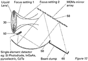
- FIG. 12 there is shown another embodiment of apparatus which avoids the use of array detectors and instead uses a microelectronic mechanical (MEM) micro mirror array 56, of a type available from Texas Instruments Corporation.
- This device 56 comprises an array of micro-mirrors which can be individually controlled to adopt two different orientations which typically have a 20° difference.
- This mirror array 56 can be used to sample the incoming intensity distribution of the beam 34 by directing some of the light beam into a beam dump 60 (typically an absorbing surface) and directing those parts of the light beam to be sampled to a diffuser or convex mirror 58, which thus reflects and focuses those portions of the light beam to be sampled onto the single detector element 50.
- a time result scan of all the pixels and the beam intensity profile can be captured.
- Devices of the type shown in Figure 10 can operate very fast as the mirror response time is typically in the region of tens of microseconds. Thus, a raster or other scan can be completed very rapidly.
- the lens 30 can be stepped through a range of focal configurations to allow the beam intensity distributions to be obtained in the same way as for an array detector 10. This apparatus allows complex intensity profiles to be measured, as opposed to the iris arrangement shown in Figure 11 .
- FIG. 13 there is shown another embodiment of apparatus which avoids the use of array detectors and instead uses a microelectronic mechanical (MEM) micro mirror array 156, of a type available from Texas Instruments Corporation.
- MEM microelectronic mechanical
- This device 156 comprises an array of micro-mirrors which can be individually controlled to adopt two different orientations which typically have a 20° difference.
- This mirror array 156 can be used to sample the incoming intensity distribution of the beam 134 by directing some of the light beam into a beam dump 160 (typically an absorbing surface) and directing those parts of the light beam to be sampled to a diffuser, lens, lens array or concave mirror (optimally an off-axis parabloid) 158, which thus reflects and focuses those portions of the light beam to be sampled onto the single detector element 150.
- a beam dump 160 typically an absorbing surface
- a diffuser, lens, lens array or concave mirror (optimally an off-axis parabloid) 158 which thus reflects and focuses those portions of the light beam to be sampled onto the single detector element 150. This allows a wide spectral coverage.
- Several single element detectors with differing spectral coverage could be placed within the focal spot of the focussing element or near the diffuser 158 to allow the device to provide a wide ranging spectral capability.
- This apparatus can be also used as a spectrally insensitive imaging device as an alternative to imaging arrays such as Charge Coupled Devices(CCD) or GaAs arrays for Infra Red light imaging.
- the mirror array 156 can be used for a very wide range of wavelengths and so the detection capability is then dictated by the single element detector 150.
- These single element detectors 150 can be made to be sensitive to wavelength sections from the UV to the far Infra red.
- the devices shown in Figure 13 can operate very fast as the mirror response time is typically in the region of tens of microseconds. Thus, a raster or other scan can be completed very rapidly.
- the other advantage of this system is that if light levels are low, blocks of pixels 157 can be scanned by appropriate positioning of a block of mirror elements 157, instead of orienting a single mirror element 156. This directs more light at the detector 150 and also allows a faster scan speed across the whole of the array 156. The resulting lower resolution image can be improved by reverting to single mirror element scans. This can also be localized to areas of interest within the image. Moreover, if it is known that the object or light beam to be scanned has elements of symmetry, the scan pattern can be changed to take advantage of this.
- the converging second moment width measurement regime can be implemented using the array pixels 157. Initially a low resolution measurement is done to identify the area of the beam which produces the highest power on the detector. Concentric circles (or other shape) of mirror array elements are activated sequentially around this point to generate a basic image. This can then be iteratively improved with raster scanning. If stray light or other light noise effects are a problem the beam dump can be replaced with a second optical element and single element detector which can be used with the first single element detector to facilitate differential detection.
- the lens 130 can be stepped through a range of focal configurations to allow the beam intensity distributions to be obtained in the same way as for an array detector.
- This apparatus allows complex intensity profiles to be measured.
Landscapes
- Physics & Mathematics (AREA)
- Spectroscopy & Molecular Physics (AREA)
- General Physics & Mathematics (AREA)
- Optics & Photonics (AREA)
- Chemical & Material Sciences (AREA)
- Analytical Chemistry (AREA)
- Photometry And Measurement Of Optical Pulse Characteristics (AREA)
Claims (14)
- System zum Ermitteln eines Ausbreitungsfaktors für die Bestimmung der Leistungsfähigkeit eines Laserlichtstrahls (18), aufweisend- einen Lichtsensor (10),- ein Linsenelement (16), betreibbar zum Fokussieren des Strahls einer zu testenden Laserlichtquelle (14) auf das Sensorelement,- wobei der Lichtsensor und das Linsenelement im Wesentlichen in einer Position relativ zueinander fixiert sind;- wobei das Linsenelement eine Linse mit variabler Brennweite ist und die Linse so einstellbar ist, dass sie ihre Brennweite derart einstellt, dass dem Lichtsensor ein variabel fokussierter Lichtstrahl an jeder Seite einer Taille zur Verfügung gestellt wird, um dadurch die Bestimmung einer Strahltaille und des Ausbreitungsfaktors des Lichtstrahls und daraus der Leistungsfähigkeit des Lichtstrahls zu ermöglichen.
- System nach Anspruch 1,
dadurch gekennzeichnet,
dass das variabel fokussierbare Linsenelement mittels elektrischer Stimulierung einstellbar ist. - System nach Anspruch 1 oder 2,
dadurch gekennzeichnet,
dass die Linse eine auf Elektrobenetzung basierende Flüssiglinse ist. - System nach Anspruch 1 oder 2,
dadurch gekennzeichnet,
dass die Linse eine Flüssigkristall-Linse ist. - System nach einem der Ansprüche 1 bis 4,
dadurch gekennzeichnet,
dass die Linse eine druckgesteuerte Flüssiglinse ist. - System nach Anspruch 1 oder 2,
dadurch gekennzeichnet,
dass die Linse eine elektrooptische Linse mit variablem Fokus ist. - System nach einem der vorhergehenden Ansprüche,
dadurch gekennzeichnet,
dass das Sensorelement ein Array von Sensoren umfasst - System nach Anspruch 7,
dadurch gekennzeichnet,
dass das Sensorelement ein CCD-Array ist. - System nach einem der Ansprüche 1 bis 6,
dadurch gekennzeichnet,
dass das Sensorelement einen Einzelelement-Detektor umfasst. - System nach Anspruch 9,
dadurch gekennzeichnet,
dass der Einzelelement-Detektor eine Silizium-Photodiode, ein InGaAs-, ein pyroelektrisches oder ein CdTe-Detektorelement ist. - System nach Anspruch 9 oder 10,
umfassend eine Auswahl- und / oder Steuerungsvorrichtung zum Ausrichten von Licht auf den Einzelelement-Detektor. - System nach Anspruch 9, 10 oder 11,
umfassend eine motorisierte Blende. - System nach einem der Ansprüche 9, 10, 11 oder 12,
umfassend ein bewegliches Spiegel-Array. - Verfahren zur Bestimmung der Eigenschaften eines Laserlichtstrahls, umfassend die Schritte:- Bereitstellen eines Sensorelements,- Bereitstellen eines Linsenelementes mit variablem Fokus, wobei das Sensorelement und das Linsenelement mit variablem Fokus im Wesentlichen in einer Position relativ zueinander fixiert sind,- Ausrichten des zu bewertenden Strahls auf das Linsenelement, wobei während eines Mess-Schrittes der Fokus des Linsenelements verändert wird, um dem Sensorelement einen variierend fokussierten Lichtstrahl an jedem Punkt einer Taille des Lichtstrahls zur Verfügung zu stellen,- daraus resultierend Ermitteln der Strahltaille sowie des Ausbreitungsfaktors des Lichtstrahls und mittels des genannten Erfassungsschritts Bestimmen der Eigenschaften des Lichtstrahls.
Applications Claiming Priority (2)
| Application Number | Priority Date | Filing Date | Title |
|---|---|---|---|
| GB0907290A GB2469993A (en) | 2009-04-28 | 2009-04-28 | Measuring the propagation properties of a light beam using a variable focus lens |
| PCT/GB2010/000848 WO2010125344A1 (en) | 2009-04-28 | 2010-04-28 | Method and system for measuring the propagation properties of a light beam |
Publications (2)
| Publication Number | Publication Date |
|---|---|
| EP2425221A1 EP2425221A1 (de) | 2012-03-07 |
| EP2425221B1 true EP2425221B1 (de) | 2017-04-12 |
Family
ID=40791927
Family Applications (1)
| Application Number | Title | Priority Date | Filing Date |
|---|---|---|---|
| EP10718255.2A Not-in-force EP2425221B1 (de) | 2009-04-28 | 2010-04-28 | Verfahren und system zur messung der ausbreitungseigenschaften eines lichtstrahls |
Country Status (4)
| Country | Link |
|---|---|
| US (1) | US8736827B2 (de) |
| EP (1) | EP2425221B1 (de) |
| GB (1) | GB2469993A (de) |
| WO (1) | WO2010125344A1 (de) |
Families Citing this family (12)
| Publication number | Priority date | Publication date | Assignee | Title |
|---|---|---|---|---|
| EP2787332B1 (de) | 2013-04-03 | 2019-02-20 | Sick Ag | Spektrometer und Verfahren zum Betrieb |
| DE102015209418A1 (de) * | 2015-05-22 | 2016-11-24 | Robert Bosch Gmbh | Scanvorrichtung und Scanverfahren |
| DE102015014387B3 (de) * | 2015-11-09 | 2017-05-11 | Primes GmbH Meßtechnik für die Produktion mit Laserstrahlung | Vorrichtung und Verfahren zur Strahlanalyse mit einem variablen optischen Element |
| DE102016009475B4 (de) | 2016-08-05 | 2019-06-19 | Primes GmbH Meßtechnik für die Produktion mit Laserstrahlung | Strahlleistungsmessung mit Aufweitung |
| DE102016011568B4 (de) | 2016-09-26 | 2019-03-07 | Primes GmbH Meßtechnik für die Produktion mit Laserstrahlung | Vorrichtung und Verfahren zur Bestimmung von räumlichen Abmessungen eines Lichtstrahls |
| US11243114B2 (en) | 2018-09-17 | 2022-02-08 | Trumpf Lasersystems For Semiconductor Manufacturing Gmbh | Method for determining at least one beam propagation parameter of a laser beam |
| TWI729403B (zh) * | 2019-05-31 | 2021-06-01 | 致茂電子股份有限公司 | 光電元件特性測量裝置 |
| TWI724673B (zh) * | 2019-12-05 | 2021-04-11 | 致茂電子股份有限公司 | 光電元件特性測量裝置 |
| CN113865829A (zh) * | 2021-10-12 | 2021-12-31 | 中国电子科技集团公司第四十四研究所 | 一种光电探测器参数测试用多通道对光装置 |
| CN118915326B (zh) * | 2024-08-30 | 2025-02-28 | 重庆理工大学 | 离轴抛物面反射镜的多孔径光束相干合成装置及其方法 |
| CN118857691B (zh) * | 2024-09-24 | 2024-11-26 | 中国工程物理研究院应用电子学研究所 | 一种基于HTM的远场光束质量β测量仪 |
| CN119756571B (zh) * | 2024-12-17 | 2025-12-16 | 武汉光至科技有限公司 | 一种光束质量分析仪 |
Family Cites Families (9)
| Publication number | Priority date | Publication date | Assignee | Title |
|---|---|---|---|---|
| JPS63298019A (ja) * | 1987-05-28 | 1988-12-05 | Ricoh Co Ltd | レ−ザ光強度分布測定用ナイフエツジ |
| JPH02271314A (ja) * | 1989-04-12 | 1990-11-06 | Canon Inc | 光走査装置 |
| JP2857459B2 (ja) * | 1990-03-15 | 1999-02-17 | 株式会社リコー | 光走査装置 |
| US5069527A (en) * | 1990-04-26 | 1991-12-03 | Coherent, Inc. | Apparatus for measuring the mode quality of a laser beam |
| FR2769375B1 (fr) * | 1997-10-08 | 2001-01-19 | Univ Joseph Fourier | Lentille a focale variable |
| US6646728B1 (en) * | 2001-07-09 | 2003-11-11 | 3D Systems, Inc. | Calibrating a focused beam of energy in a solid freeform fabrication apparatus by measuring the propagation characteristics of the beam |
| US7359124B1 (en) * | 2004-04-30 | 2008-04-15 | Louisiana Tech University Research Foundation As A Division Of The Louisiana Tech University Foundation | Wide-angle variable focal length lens system |
| KR100711254B1 (ko) * | 2005-11-01 | 2007-04-25 | 삼성전기주식회사 | 액체 줌 렌즈 |
| KR100723244B1 (ko) * | 2005-12-27 | 2007-05-29 | 삼성전기주식회사 | 전기습윤을 이용한 액체렌즈 제조방법 및 이에 의한액체렌즈 |
-
2009
- 2009-04-28 GB GB0907290A patent/GB2469993A/en not_active Withdrawn
-
2010
- 2010-04-28 US US13/265,310 patent/US8736827B2/en not_active Expired - Fee Related
- 2010-04-28 EP EP10718255.2A patent/EP2425221B1/de not_active Not-in-force
- 2010-04-28 WO PCT/GB2010/000848 patent/WO2010125344A1/en not_active Ceased
Non-Patent Citations (1)
| Title |
|---|
| None * |
Also Published As
| Publication number | Publication date |
|---|---|
| US20120086936A1 (en) | 2012-04-12 |
| US8736827B2 (en) | 2014-05-27 |
| EP2425221A1 (de) | 2012-03-07 |
| GB0907290D0 (en) | 2009-06-10 |
| WO2010125344A1 (en) | 2010-11-04 |
| GB2469993A (en) | 2010-11-10 |
Similar Documents
| Publication | Publication Date | Title |
|---|---|---|
| EP2425221B1 (de) | Verfahren und system zur messung der ausbreitungseigenschaften eines lichtstrahls | |
| US6678042B2 (en) | Laser beam multimeter | |
| US7898668B2 (en) | Terahertz spectrometer | |
| CN107144419A (zh) | 一种基于夏克‐哈特曼波前传感器的光学系统波像差测量装置与方法 | |
| CN106052585A (zh) | 一种面形检测装置与检测方法 | |
| CN101539457A (zh) | 基于mems微镜阵列的微型光谱仪 | |
| KR20210149839A (ko) | 레이저 빔의 초점 위치를 결정하는 장치 및 방법 | |
| Sauter et al. | Simultaneous beam steering and shaping using a single-interface optofluidic component | |
| WO2017033037A1 (en) | Terahertz wavefront measurement system and method | |
| US8009280B1 (en) | Wavefront characterization and correction | |
| WO2016007925A1 (en) | Spectral imaging of a sample using a plurality of discrete mid-infrared wavelengths | |
| CN106404189B (zh) | 测量太赫兹光束参数的方法 | |
| Sheikh et al. | Motion-free hybrid design laser beam propagation analyzer using a digital micromirror device and a variable focus liquid lens | |
| EP2715319A1 (de) | Wellenfront-messvorrichtung, wellenfront-messverfahren und objektmessvorrichtung | |
| EP2554974A1 (de) | Vorrichtung zur erkennung elektromagnetischer wellen | |
| KR20170059338A (ko) | 광학 측정 장치 및 이를 구비하는 전자 기기 | |
| CN220170884U (zh) | 一种红外光谱非线性折射率干涉测量系统 | |
| CN112268861A (zh) | 一种双波长飞秒抽运探测热反射系统 | |
| CN115493695B (zh) | 微区瞬态吸收光谱测量系统 | |
| Báez-Chorro et al. | Accurate beam profile characterization in THz transmission imaging systems | |
| Tan et al. | Effect of adaptive optical system on the capability of lidar detection in atmosphere | |
| Müller et al. | Feedback stabilization of quantum cascade laser beams for stand-off applications | |
| CN112268860A (zh) | 一种双波长飞秒抽运探测热反射系统 | |
| RU2808750C1 (ru) | Устройство для измерения параметров и характеристик источников излучения | |
| US20250305873A1 (en) | System and method for sampling terahertz pulses using modulated difference-frequency in repetition rates of femtosecond lasers |
Legal Events
| Date | Code | Title | Description |
|---|---|---|---|
| PUAI | Public reference made under article 153(3) epc to a published international application that has entered the european phase |
Free format text: ORIGINAL CODE: 0009012 |
|
| 17P | Request for examination filed |
Effective date: 20111018 |
|
| AK | Designated contracting states |
Kind code of ref document: A1 Designated state(s): AT BE BG CH CY CZ DE DK EE ES FI FR GB GR HR HU IE IS IT LI LT LU LV MC MK MT NL NO PL PT RO SE SI SK SM TR |
|
| DAX | Request for extension of the european patent (deleted) | ||
| GRAP | Despatch of communication of intention to grant a patent |
Free format text: ORIGINAL CODE: EPIDOSNIGR1 |
|
| INTG | Intention to grant announced |
Effective date: 20160628 |
|
| RIN1 | Information on inventor provided before grant (corrected) |
Inventor name: HALL, SIMON RICHARD GEOFFREY |
|
| GRAJ | Information related to disapproval of communication of intention to grant by the applicant or resumption of examination proceedings by the epo deleted |
Free format text: ORIGINAL CODE: EPIDOSDIGR1 |
|
| STAA | Information on the status of an ep patent application or granted ep patent |
Free format text: STATUS: REQUEST FOR EXAMINATION WAS MADE |
|
| INTC | Intention to grant announced (deleted) | ||
| GRAP | Despatch of communication of intention to grant a patent |
Free format text: ORIGINAL CODE: EPIDOSNIGR1 |
|
| STAA | Information on the status of an ep patent application or granted ep patent |
Free format text: STATUS: GRANT OF PATENT IS INTENDED |
|
| INTG | Intention to grant announced |
Effective date: 20161220 |
|
| GRAS | Grant fee paid |
Free format text: ORIGINAL CODE: EPIDOSNIGR3 |
|
| GRAA | (expected) grant |
Free format text: ORIGINAL CODE: 0009210 |
|
| STAA | Information on the status of an ep patent application or granted ep patent |
Free format text: STATUS: THE PATENT HAS BEEN GRANTED |
|
| AK | Designated contracting states |
Kind code of ref document: B1 Designated state(s): AT BE BG CH CY CZ DE DK EE ES FI FR GB GR HR HU IE IS IT LI LT LU LV MC MK MT NL NO PL PT RO SE SI SK SM TR |
|
| REG | Reference to a national code |
Ref country code: GB Ref legal event code: FG4D |
|
| REG | Reference to a national code |
Ref country code: CH Ref legal event code: EP |
|
| REG | Reference to a national code |
Ref country code: FR Ref legal event code: PLFP Year of fee payment: 8 |
|
| REG | Reference to a national code |
Ref country code: IE Ref legal event code: FG4D |
|
| REG | Reference to a national code |
Ref country code: AT Ref legal event code: REF Ref document number: 884383 Country of ref document: AT Kind code of ref document: T Effective date: 20170515 |
|
| REG | Reference to a national code |
Ref country code: DE Ref legal event code: R096 Ref document number: 602010041467 Country of ref document: DE |
|
| PGFP | Annual fee paid to national office [announced via postgrant information from national office to epo] |
Ref country code: DE Payment date: 20170428 Year of fee payment: 8 Ref country code: FR Payment date: 20170502 Year of fee payment: 8 |
|
| REG | Reference to a national code |
Ref country code: NL Ref legal event code: MP Effective date: 20170412 |
|
| REG | Reference to a national code |
Ref country code: LT Ref legal event code: MG4D |
|
| REG | Reference to a national code |
Ref country code: AT Ref legal event code: MK05 Ref document number: 884383 Country of ref document: AT Kind code of ref document: T Effective date: 20170412 |
|
| PG25 | Lapsed in a contracting state [announced via postgrant information from national office to epo] |
Ref country code: NL Free format text: LAPSE BECAUSE OF FAILURE TO SUBMIT A TRANSLATION OF THE DESCRIPTION OR TO PAY THE FEE WITHIN THE PRESCRIBED TIME-LIMIT Effective date: 20170412 |
|
| PG25 | Lapsed in a contracting state [announced via postgrant information from national office to epo] |
Ref country code: AT Free format text: LAPSE BECAUSE OF FAILURE TO SUBMIT A TRANSLATION OF THE DESCRIPTION OR TO PAY THE FEE WITHIN THE PRESCRIBED TIME-LIMIT Effective date: 20170412 Ref country code: HR Free format text: LAPSE BECAUSE OF FAILURE TO SUBMIT A TRANSLATION OF THE DESCRIPTION OR TO PAY THE FEE WITHIN THE PRESCRIBED TIME-LIMIT Effective date: 20170412 Ref country code: NO Free format text: LAPSE BECAUSE OF FAILURE TO SUBMIT A TRANSLATION OF THE DESCRIPTION OR TO PAY THE FEE WITHIN THE PRESCRIBED TIME-LIMIT Effective date: 20170712 Ref country code: GR Free format text: LAPSE BECAUSE OF FAILURE TO SUBMIT A TRANSLATION OF THE DESCRIPTION OR TO PAY THE FEE WITHIN THE PRESCRIBED TIME-LIMIT Effective date: 20170713 Ref country code: FI Free format text: LAPSE BECAUSE OF FAILURE TO SUBMIT A TRANSLATION OF THE DESCRIPTION OR TO PAY THE FEE WITHIN THE PRESCRIBED TIME-LIMIT Effective date: 20170412 Ref country code: LT Free format text: LAPSE BECAUSE OF FAILURE TO SUBMIT A TRANSLATION OF THE DESCRIPTION OR TO PAY THE FEE WITHIN THE PRESCRIBED TIME-LIMIT Effective date: 20170412 Ref country code: ES Free format text: LAPSE BECAUSE OF FAILURE TO SUBMIT A TRANSLATION OF THE DESCRIPTION OR TO PAY THE FEE WITHIN THE PRESCRIBED TIME-LIMIT Effective date: 20170412 |
|
| PGFP | Annual fee paid to national office [announced via postgrant information from national office to epo] |
Ref country code: GB Payment date: 20170712 Year of fee payment: 8 |
|
| PG25 | Lapsed in a contracting state [announced via postgrant information from national office to epo] |
Ref country code: BG Free format text: LAPSE BECAUSE OF FAILURE TO SUBMIT A TRANSLATION OF THE DESCRIPTION OR TO PAY THE FEE WITHIN THE PRESCRIBED TIME-LIMIT Effective date: 20170712 Ref country code: PL Free format text: LAPSE BECAUSE OF FAILURE TO SUBMIT A TRANSLATION OF THE DESCRIPTION OR TO PAY THE FEE WITHIN THE PRESCRIBED TIME-LIMIT Effective date: 20170412 Ref country code: SE Free format text: LAPSE BECAUSE OF FAILURE TO SUBMIT A TRANSLATION OF THE DESCRIPTION OR TO PAY THE FEE WITHIN THE PRESCRIBED TIME-LIMIT Effective date: 20170412 Ref country code: IS Free format text: LAPSE BECAUSE OF FAILURE TO SUBMIT A TRANSLATION OF THE DESCRIPTION OR TO PAY THE FEE WITHIN THE PRESCRIBED TIME-LIMIT Effective date: 20170812 Ref country code: LV Free format text: LAPSE BECAUSE OF FAILURE TO SUBMIT A TRANSLATION OF THE DESCRIPTION OR TO PAY THE FEE WITHIN THE PRESCRIBED TIME-LIMIT Effective date: 20170412 |
|
| REG | Reference to a national code |
Ref country code: CH Ref legal event code: PL |
|
| REG | Reference to a national code |
Ref country code: DE Ref legal event code: R097 Ref document number: 602010041467 Country of ref document: DE |
|
| REG | Reference to a national code |
Ref country code: IE Ref legal event code: MM4A |
|
| PG25 | Lapsed in a contracting state [announced via postgrant information from national office to epo] |
Ref country code: CZ Free format text: LAPSE BECAUSE OF FAILURE TO SUBMIT A TRANSLATION OF THE DESCRIPTION OR TO PAY THE FEE WITHIN THE PRESCRIBED TIME-LIMIT Effective date: 20170412 Ref country code: DK Free format text: LAPSE BECAUSE OF FAILURE TO SUBMIT A TRANSLATION OF THE DESCRIPTION OR TO PAY THE FEE WITHIN THE PRESCRIBED TIME-LIMIT Effective date: 20170412 Ref country code: MC Free format text: LAPSE BECAUSE OF FAILURE TO SUBMIT A TRANSLATION OF THE DESCRIPTION OR TO PAY THE FEE WITHIN THE PRESCRIBED TIME-LIMIT Effective date: 20170412 Ref country code: EE Free format text: LAPSE BECAUSE OF FAILURE TO SUBMIT A TRANSLATION OF THE DESCRIPTION OR TO PAY THE FEE WITHIN THE PRESCRIBED TIME-LIMIT Effective date: 20170412 Ref country code: SK Free format text: LAPSE BECAUSE OF FAILURE TO SUBMIT A TRANSLATION OF THE DESCRIPTION OR TO PAY THE FEE WITHIN THE PRESCRIBED TIME-LIMIT Effective date: 20170412 Ref country code: RO Free format text: LAPSE BECAUSE OF FAILURE TO SUBMIT A TRANSLATION OF THE DESCRIPTION OR TO PAY THE FEE WITHIN THE PRESCRIBED TIME-LIMIT Effective date: 20170412 |
|
| PLBE | No opposition filed within time limit |
Free format text: ORIGINAL CODE: 0009261 |
|
| STAA | Information on the status of an ep patent application or granted ep patent |
Free format text: STATUS: NO OPPOSITION FILED WITHIN TIME LIMIT |
|
| PG25 | Lapsed in a contracting state [announced via postgrant information from national office to epo] |
Ref country code: LU Free format text: LAPSE BECAUSE OF NON-PAYMENT OF DUE FEES Effective date: 20170428 Ref country code: LI Free format text: LAPSE BECAUSE OF NON-PAYMENT OF DUE FEES Effective date: 20170430 Ref country code: SM Free format text: LAPSE BECAUSE OF FAILURE TO SUBMIT A TRANSLATION OF THE DESCRIPTION OR TO PAY THE FEE WITHIN THE PRESCRIBED TIME-LIMIT Effective date: 20170412 Ref country code: CH Free format text: LAPSE BECAUSE OF NON-PAYMENT OF DUE FEES Effective date: 20170430 Ref country code: IT Free format text: LAPSE BECAUSE OF FAILURE TO SUBMIT A TRANSLATION OF THE DESCRIPTION OR TO PAY THE FEE WITHIN THE PRESCRIBED TIME-LIMIT Effective date: 20170412 |
|
| 26N | No opposition filed |
Effective date: 20180115 |
|
| REG | Reference to a national code |
Ref country code: BE Ref legal event code: MM Effective date: 20170430 |
|
| PG25 | Lapsed in a contracting state [announced via postgrant information from national office to epo] |
Ref country code: IE Free format text: LAPSE BECAUSE OF NON-PAYMENT OF DUE FEES Effective date: 20170428 |
|
| PG25 | Lapsed in a contracting state [announced via postgrant information from national office to epo] |
Ref country code: BE Free format text: LAPSE BECAUSE OF NON-PAYMENT OF DUE FEES Effective date: 20170430 Ref country code: SI Free format text: LAPSE BECAUSE OF FAILURE TO SUBMIT A TRANSLATION OF THE DESCRIPTION OR TO PAY THE FEE WITHIN THE PRESCRIBED TIME-LIMIT Effective date: 20170412 |
|
| PG25 | Lapsed in a contracting state [announced via postgrant information from national office to epo] |
Ref country code: MT Free format text: LAPSE BECAUSE OF NON-PAYMENT OF DUE FEES Effective date: 20170428 |
|
| REG | Reference to a national code |
Ref country code: DE Ref legal event code: R119 Ref document number: 602010041467 Country of ref document: DE |
|
| GBPC | Gb: european patent ceased through non-payment of renewal fee |
Effective date: 20180428 |
|
| PG25 | Lapsed in a contracting state [announced via postgrant information from national office to epo] |
Ref country code: DE Free format text: LAPSE BECAUSE OF NON-PAYMENT OF DUE FEES Effective date: 20181101 |
|
| PG25 | Lapsed in a contracting state [announced via postgrant information from national office to epo] |
Ref country code: GB Free format text: LAPSE BECAUSE OF NON-PAYMENT OF DUE FEES Effective date: 20180428 |
|
| PG25 | Lapsed in a contracting state [announced via postgrant information from national office to epo] |
Ref country code: FR Free format text: LAPSE BECAUSE OF NON-PAYMENT OF DUE FEES Effective date: 20180430 |
|
| PG25 | Lapsed in a contracting state [announced via postgrant information from national office to epo] |
Ref country code: HU Free format text: LAPSE BECAUSE OF FAILURE TO SUBMIT A TRANSLATION OF THE DESCRIPTION OR TO PAY THE FEE WITHIN THE PRESCRIBED TIME-LIMIT; INVALID AB INITIO Effective date: 20100428 |
|
| PG25 | Lapsed in a contracting state [announced via postgrant information from national office to epo] |
Ref country code: CY Free format text: LAPSE BECAUSE OF NON-PAYMENT OF DUE FEES Effective date: 20170412 |
|
| PG25 | Lapsed in a contracting state [announced via postgrant information from national office to epo] |
Ref country code: MK Free format text: LAPSE BECAUSE OF FAILURE TO SUBMIT A TRANSLATION OF THE DESCRIPTION OR TO PAY THE FEE WITHIN THE PRESCRIBED TIME-LIMIT Effective date: 20170412 |
|
| PG25 | Lapsed in a contracting state [announced via postgrant information from national office to epo] |
Ref country code: TR Free format text: LAPSE BECAUSE OF FAILURE TO SUBMIT A TRANSLATION OF THE DESCRIPTION OR TO PAY THE FEE WITHIN THE PRESCRIBED TIME-LIMIT Effective date: 20170412 |
|
| PG25 | Lapsed in a contracting state [announced via postgrant information from national office to epo] |
Ref country code: PT Free format text: LAPSE BECAUSE OF FAILURE TO SUBMIT A TRANSLATION OF THE DESCRIPTION OR TO PAY THE FEE WITHIN THE PRESCRIBED TIME-LIMIT Effective date: 20170412 |