EP2425192B1 - Anchoring means - Google Patents
Anchoring means Download PDFInfo
- Publication number
- EP2425192B1 EP2425192B1 EP10718719.7A EP10718719A EP2425192B1 EP 2425192 B1 EP2425192 B1 EP 2425192B1 EP 10718719 A EP10718719 A EP 10718719A EP 2425192 B1 EP2425192 B1 EP 2425192B1
- Authority
- EP
- European Patent Office
- Prior art keywords
- anchoring means
- mid section
- anchoring
- arm
- respect
- Prior art date
- Legal status (The legal status is an assumption and is not a legal conclusion. Google has not performed a legal analysis and makes no representation as to the accuracy of the status listed.)
- Active
Links
Images
Classifications
-
- F—MECHANICAL ENGINEERING; LIGHTING; HEATING; WEAPONS; BLASTING
- F27—FURNACES; KILNS; OVENS; RETORTS
- F27D—DETAILS OR ACCESSORIES OF FURNACES, KILNS, OVENS OR RETORTS, IN SO FAR AS THEY ARE OF KINDS OCCURRING IN MORE THAN ONE KIND OF FURNACE
- F27D1/00—Casings; Linings; Walls; Roofs
- F27D1/14—Supports for linings
- F27D1/141—Anchors therefor
Definitions
- the invention relates to an anchoring means according to the preamble of claim 1
- arms interconnected with the mid section of the anchoring means are bend with respect to the mid section over an angle between 20° and 40° whereas the free ends of the arms interconnected with the mid section are bended with respect to the arms such that the free ends extend parallel to the plains, that are positioned in essence perpendicular to a plain extending parallel to the mid section.
- the starting piece shown in figure 1 for forming the anchoring means is obtained by blanking out a polygonal plate section or starting plate. Therein the starting piece is build up of a multigonal mid section 1, in the embodiment shown being a substantially hexagonal mid section. It may be clear that also other multigonals are considered, such as quadragonal, pentagonal, and octagonal. A too small or too large number of arms will not benefit the functionality and robustness of the anchoring means.
- To the mid section 9 six legs 2, forming one part with the mid section, link to the circumferal edge of the mid section, which legs are separated from one another by blanked out slots 3.
- each leg 2 increases gradually in a direction turned away from the mid section 1, whereas the free ends 4 of legs 2 have a rectangular form.
- An increasing width provides amongst others a improved accessibility, whereby air chambers are prevented, and further sufficient robustness.
- a rectangular form provides in particular a good fixture with the base.
- a further slot like hole 5 is formed by blanking out in a longitudinal direction of the leg.
- the slot like holes preferably have a relative surface, with respect to that of the legs, which is between 30 and 100% thereof, such as 50%. This provides a good accessibility and maintenance of robustness.
- a round hole 6 is applied.
- the legs 3 are bended over the bending lines 7 with respect to the mid section 1 as is schematically indicated in figure 1 over an angle ⁇ between 20° and 40°, such as somewhat smaller than 30°. Other angles will not be functional, in a sense that for instance air chambers will remain. Further an anchoring means having larger angles is difficult to manufacture, and it is also more sensitive to breakage. In comparison to the anchoring means as disclosed in NL 193.073 there are important differences.
- a further advantage of the present anchoring means is that the concrete is easier to be positioned. This reduces the chance of mistakes when positioning, such as the appearance of air chambers, insufficient attachment, increased sensitivity to breakage, etcetera. As a consequence less or no anchoring means have to be removed and placed again.
- the free ends 4 of legs 2 are bended with respect to legs 2 along folding lines 8 schematically shown in figure 1 in such a way that the free ends 4 of legs 2 extend parallel to plains, which extend perpendicular to a plain which is parallel to the mid section 1.
- the length of a part of a leg in between folding legs 7 and 8 is in a radial direction measured from the heart of the hole 6 about equal to the distance between two folding lines 7 which are positioned opposing each other, and limiting the mid section 1.
- Such a length provides extra robustness and stiffness to the construction, as well as an improved manageability. The functionality thereof is as a consequence improved. Also from a aesthetic point of view the present embodiment appears neat and tidy.
- the plate section had a thickness of between 1.2 mm and 3.0 mm, preferably a thickness of between 1.5 mm and 2.0 mm.
- a too large thickness has as a consequence that the present anchoring means is difficult or not manageable for a person that is applying the anchoring means.
- a too small thickness has as a consequence that the anchoring means is for example mechanically too weak.
- connection part in the form of a nut 9 is welded in the area of a hole 6 being formed in the mid section.
- Such a pin 10 is build from a massive shaft 11, which shaft forms a single part with an external screw thread 12 being provided thereon. Thereby the external diameter of the part 12 is smaller then the external diameter of the part 11, such that at the transition between parts 11 and 12 a collar 13 is formed.
- the lining pins 10 are being welded to the object with an end thereof turned away from the screw tread end 12, for instance by pressing the pins with a suitable tool against the wall and heating the ends of the pins that are to be welded.
- the anchoring means are applied to the pins which are welded to the object by screwing an anchor means on each pin using the nut 9 welded to each respectively anchoring means.
- the nut 9 will at a given moment come in contact with collar 13 whereby it is prevented that the anchoring means is screwed too far to pin 11 and further that the anchoring means is at a required distance in each instance with respect to the object to be lined and unwanted deformation of the anchoring means will be prevented.
Landscapes
- Engineering & Computer Science (AREA)
- Mechanical Engineering (AREA)
- General Engineering & Computer Science (AREA)
- Joining Of Building Structures In Genera (AREA)
- Building Environments (AREA)
- Mobile Radio Communication Systems (AREA)
Description
- The invention relates to an anchoring means according to the preamble of claim 1
- Such an anchoring means is known from the Dutch patent
193.073 - As such this known anchoring means suffices, but with some lining materials and/or under difficult working conditions when applying the lining material on objects it may happen that the space between the anchoring means and the object is not thoroughly filled with lining material and underneath the anchoring means a non filled space or "air chamber" remains, which is unwanted.
- According to the invention arms interconnected with the mid section of the anchoring means are bend with respect to the mid section over an angle between 20° and 40° whereas the free ends of the arms interconnected with the mid section are bended with respect to the arms such that the free ends extend parallel to the plains, that are positioned in essence perpendicular to a plain extending parallel to the mid section.
- In practise it has been experienced that for this embodiment of the anchoring means according to the invention applying the lining material effectively between the given object and the anchoring means can be established without danger of remaining "air chambers" between the anchoring means and the object to which the anchoring means is applied, such that the lining applied is effected very effectively.
- The invention will be explained in detail with respect to the accompanying figures.
-
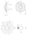
Figure 1 shows a top view of a blanked out flat plate part, from which the anchoring means is being manufactured by folding the plate parts. -
Figure 2 shows a side view of an anchoring means. -
Figure 3 shows a view of the anchoring means shown infigure 2 in the direction according to arrow III infigure 2 . -
Figure 4 shows a pin being used for attaching an anchoring means to an object. - The starting piece shown in
figure 1 for forming the anchoring means is obtained by blanking out a polygonal plate section or starting plate. Therein the starting piece is build up of a multigonal mid section 1, in the embodiment shown being a substantially hexagonal mid section. It may be clear that also other multigonals are considered, such as quadragonal, pentagonal, and octagonal. A too small or too large number of arms will not benefit the functionality and robustness of the anchoring means. To the mid section 9 six legs 2, forming one part with the mid section, link to the circumferal edge of the mid section, which legs are separated from one another by blanked outslots 3. Therein the width of each leg 2 increases gradually in a direction turned away from the mid section 1, whereas the free ends 4 of legs 2 have a rectangular form. An increasing width provides amongst others a improved accessibility, whereby air chambers are prevented, and further sufficient robustness. A rectangular form provides in particular a good fixture with the base. In each of the legs a further slot likehole 5 is formed by blanking out in a longitudinal direction of the leg. The slot like holes preferably have a relative surface, with respect to that of the legs, which is between 30 and 100% thereof, such as 50%. This provides a good accessibility and maintenance of robustness. In the hart of the mid section 1 a round hole 6 is applied. - For the manufacturing of the anchoring means as shown in
figures 2 and 3 thelegs 3 are bended over the bending lines 7 with respect to the mid section 1 as is schematically indicated infigure 1 over an angle α between 20° and 40°, such as somewhat smaller than 30°. Other angles will not be functional, in a sense that for instance air chambers will remain. Further an anchoring means having larger angles is difficult to manufacture, and it is also more sensitive to breakage. In comparison to the anchoring means as disclosed inNL 193.073 - A further important difference in comparison to the anchoring means disclosed in
NL 193.073 - The free ends 4 of legs 2 are bended with respect to legs 2 along folding lines 8 schematically shown in
figure 1 in such a way that the free ends 4 of legs 2 extend parallel to plains, which extend perpendicular to a plain which is parallel to the mid section 1. The length of a part of a leg in between folding legs 7 and 8 is in a radial direction measured from the hart of the hole 6 about equal to the distance between two folding lines 7 which are positioned opposing each other, and limiting the mid section 1. Such a length provides extra robustness and stiffness to the construction, as well as an improved manageability. The functionality thereof is as a consequence improved. Also from a aesthetic point of view the present embodiment appears neat and tidy. - In an example the plate section had a thickness of between 1.2 mm and 3.0 mm, preferably a thickness of between 1.5 mm and 2.0 mm. A too large thickness has as a consequence that the present anchoring means is difficult or not manageable for a person that is applying the anchoring means. A too small thickness has as a consequence that the anchoring means is for example mechanically too weak.
- As is shown further in
figure 3 between the bended legs 2 and the mid section 1 a connection part in the form of a nut 9 is welded in the area of a hole 6 being formed in the mid section. - For the attachment of the anchoring means to an object formed out of metal, which is to be applied with a fire proof and/of a wear resistant lining material, use is made of pens or styles as is shown in
figure 4 . - Such a
pin 10 is build from a massive shaft 11, which shaft forms a single part with anexternal screw thread 12 being provided thereon. Thereby the external diameter of thepart 12 is smaller then the external diameter of the part 11, such that at the transition between parts 11 and 12 acollar 13 is formed. - For attaching of the required number of anchoring means to an object provided the
lining pins 10 are being welded to the object with an end thereof turned away from thescrew tread end 12, for instance by pressing the pins with a suitable tool against the wall and heating the ends of the pins that are to be welded. - Subsequently the anchoring means are applied to the pins which are welded to the object by screwing an anchor means on each pin using the nut 9 welded to each respectively anchoring means. By screwing the anchoring means to the pin the nut 9 will at a given moment come in contact with
collar 13 whereby it is prevented that the anchoring means is screwed too far to pin 11 and further that the anchoring means is at a required distance in each instance with respect to the object to be lined and unwanted deformation of the anchoring means will be prevented. - In practice it is observed that in particular by the acute development of the relatively long arm 2 being connected to the mid section 1, that can resiliently diverse, the space in between the anchoring means and the object to be lined can effectively be filled with the lining material in an easy way as can be accomplished and the presence of optional air chambers can be prevented in the space between the anchoring means and the object to be lined.
Claims (8)
- Anchoring means for providing a fireproof and/or wear resistant lining on an object made of metal, wherein the build-up of a polygonal folded base portion is intended to be fixed to the object by means of a to the object welded pin, which is provided with an anchoring thread for receiving an attachment part attached to a polygonal mid section of the anchoring means, comprising an internal thread, wherein lips which extend transversely to said polygonal base portion, join the edges of said base portion, which lips are bend over an angle with respect to said mid section and having mutually enclosing bending lines, characterised in that the arms joined with the mid section of the anchoring means are bend with respect to the mid section over an angle between 20° and 40°, whereas the free ends of the arms joined with the mid section are bend with respect to the arms such that the free ends extend parallel to the plains, that are positioned in essence perpendicular to a plain extending parallel to the mid section.
- Anchoring means according to claim 1, characterised in that the arms are bend with respect to the mid section over an angle between 20° and 30°.
- Anchoring means according to any one of the preceding claims, characterised in that measured in a radial direction the length of an arm in between folding lines around which the arm is bended with respect to the mid section and the folding line around which the free end of the arm is bend with respect to the remaining part of the arm is about equal to the distance between two folding lines which are positioned opposing each other and around which two arms are bend with respect to the mid section.
- Anchoring means according to any one of the preceding claims, characterised in that the width of an arm increases gradually in a direction turned away from the mid section.
- Anchoring means according to any one of the preceding claims, characterised in that in an arm a further slot like hole is provided in a longitudinal direction of the arm.
- Anchoring means according to any one of the preceding claims, characterised in that a bend free end of an arm has an essentially rectangular form.
- Anchoring means according to any one of the preceding claims, characterised in that the plate section has a thickness of between 1.2 mm and 3.0 mm, preferably a thickness of between 1.5 mm and 2.0 mm.
- Method for applying an anchoring means according to any one of the preceding claims using an to the object attached pin, which pin is provided with an anchoring thread, characterised in that use is made of a to the object welded pin, which is provided with a part having an external anchoring thread provided on an end thereof turned away from the object, which part fits to a part of the pin having a larger diameter, such that at the transition between the part having an anchoring thread and the part of the pin having a larger diameter a collar is formed, coming into contact, by screwing the anchoring means onto the pin, with the attachment part, comprising an internal anchoring thread attached to the mid section of the anchoring means.
Applications Claiming Priority (2)
| Application Number | Priority Date | Filing Date | Title |
|---|---|---|---|
| NL1036914A NL1036914C2 (en) | 2009-04-29 | 2009-04-29 | ANCHORING BODY. |
| PCT/NL2010/050232 WO2010126360A1 (en) | 2009-04-29 | 2010-04-26 | Anchoring means |
Publications (2)
| Publication Number | Publication Date |
|---|---|
| EP2425192A1 EP2425192A1 (en) | 2012-03-07 |
| EP2425192B1 true EP2425192B1 (en) | 2013-06-05 |
Family
ID=41413089
Family Applications (1)
| Application Number | Title | Priority Date | Filing Date |
|---|---|---|---|
| EP10718719.7A Active EP2425192B1 (en) | 2009-04-29 | 2010-04-26 | Anchoring means |
Country Status (5)
| Country | Link |
|---|---|
| US (1) | US9127890B2 (en) |
| EP (1) | EP2425192B1 (en) |
| BR (1) | BRPI1016125B1 (en) |
| NL (1) | NL1036914C2 (en) |
| WO (1) | WO2010126360A1 (en) |
Cited By (2)
| Publication number | Priority date | Publication date | Assignee | Title |
|---|---|---|---|---|
| CN103398060A (en) * | 2013-08-08 | 2013-11-20 | 抚顺利元石化配件有限公司 | Intensified anchoring part with single-layer lining |
| CN103603856A (en) * | 2013-11-29 | 2014-02-26 | 李铭山 | Breathing ring anchoring nail |
Families Citing this family (49)
| Publication number | Priority date | Publication date | Assignee | Title |
|---|---|---|---|---|
| US8107950B2 (en) * | 2008-01-25 | 2012-01-31 | Telefonaktiebolaget Lm Ericsson (Publ) | Inter-RAT/ frequency automatic neighbor relation list management |
| EP3661304A1 (en) | 2009-06-19 | 2020-06-03 | Mitsubishi Electric Corporation | Mobile communication system |
| JP4989746B2 (en) * | 2010-04-30 | 2012-08-01 | 株式会社エヌ・ティ・ティ・ドコモ | Mobile communication method and mobile station |
| WO2011137579A1 (en) * | 2010-05-03 | 2011-11-10 | 上海贝尔股份有限公司 | Handover method used in radio communication network with carrier aggregation and apparatus thereof |
| EP2577926B1 (en) * | 2010-05-25 | 2018-07-25 | InterDigital Patent Holdings, Inc. | Retuning gaps and scheduling gaps in discontinuous reception |
| KR101852814B1 (en) * | 2010-06-18 | 2018-04-27 | 엘지전자 주식회사 | Method of transmitting power headroom information at user equipment in wireless communication system and apparatus thereof |
| EP2583404A1 (en) | 2010-06-18 | 2013-04-24 | Kyocera Corporation | Control channel architecture with control information distributed over multiple subframes on different carriers |
| CN102348226B (en) | 2010-07-27 | 2016-01-13 | 索尼公司 | Method, device and system for switching cells in a communication system supporting carrier aggregation |
| CN102348230B (en) | 2010-07-27 | 2016-05-04 | 索尼公司 | The method, apparatus and system of switching cell in the communication system of support carrier convergence |
| BR112013002311B1 (en) * | 2010-07-30 | 2021-11-23 | Deutsche Telekom Ag | METHOD FOR CONTROLLING ACCESS OF USER EQUIPMENT TO A PUBLIC MOBILE PHONE NETWORK AND PUBLIC MOBILE PHONE NETWORK |
| EP2675078A4 (en) * | 2011-02-11 | 2018-02-28 | Electronics and Telecommunications Research Institute | Wireless communication system using multiple transmission and reception points |
| US8837304B2 (en) | 2011-04-08 | 2014-09-16 | Sharp Kabushiki Kaisha | Devices for multi-group communications |
| GB2491866B (en) | 2011-06-15 | 2015-10-14 | Sca Ipla Holdings Inc | Apparatus and methods for selecting carriers to camp on to in a wireless telecommunications system supporting a plurality of carriers |
| US11974295B2 (en) * | 2011-07-25 | 2024-04-30 | Nec Corporation | Communication system |
| EP2738991B1 (en) | 2011-07-27 | 2019-09-18 | LG Electronics Inc. | Method for transmitting an uplink reference signal in a multi-node system and terminal using same |
| EP2557855B1 (en) * | 2011-08-10 | 2017-11-01 | Alcatel Lucent | A sensor, a mobile user terminal and a method of a sensor sensing a mobile user terminal |
| KR20130061936A (en) * | 2011-12-02 | 2013-06-12 | 삼성전자주식회사 | Apparatus and method for safe communication in wireless communication system |
| CN103988559B (en) * | 2011-12-20 | 2018-02-23 | 英特尔公司 | Use the multicast service of unicast sub-frame |
| US9450719B2 (en) * | 2012-03-05 | 2016-09-20 | Lg Electronics Inc. | Method and apparatus for transmitting or receiving downlink signal |
| US9338773B2 (en) * | 2012-03-26 | 2016-05-10 | Qualcomm Incorporated | Common search space for EPDCCH in LTE |
| US9294141B2 (en) | 2012-05-11 | 2016-03-22 | Qualcomm Incorporated | System and methods for improving page decode performance during reading of system information on a multi-SIM wireless communication device |
| US8958847B2 (en) * | 2012-05-11 | 2015-02-17 | Qualcomm Incorporated | Methods and apparatuses for optimization of multiple subscription device performance |
| CN104521305B (en) | 2012-08-02 | 2019-06-28 | 三菱电机株式会社 | Communication Systems |
| US9699701B2 (en) * | 2012-08-10 | 2017-07-04 | Qualcomm Incorporated | Mobility operation in LTE |
| US20140092758A1 (en) * | 2012-10-02 | 2014-04-03 | Research In Motion Limited | Processing for a carrier according to a carrier type |
| US20140092879A1 (en) * | 2012-10-02 | 2014-04-03 | Zte Wistron Telecom Ab | Downlink transmission point selection in a wireless heterogeneous network |
| KR20180006493A (en) | 2012-10-05 | 2018-01-17 | 닛본 덴끼 가부시끼가이샤 | Wireless communication system, wireless stations, wireless terminal, communication control method, and computer-readable medium |
| US9131434B2 (en) | 2012-10-19 | 2015-09-08 | Blackberry Limited | Using a cell as a pathloss or timing reference |
| US11356216B2 (en) * | 2013-01-10 | 2022-06-07 | Texas Instruments Incorporated | Methods and apparatus for dual connectivity operation in a wireless communication network |
| KR101950863B1 (en) * | 2013-01-16 | 2019-02-22 | 삼성전자주식회사 | Apparatus, block decoding unit and method for receiving signal in radio communication system |
| US9918299B2 (en) | 2013-08-06 | 2018-03-13 | Sun Patent Trust | Wireless communication method for device to device communication and user equipment |
| CN104703171A (en) * | 2013-12-07 | 2015-06-10 | 北京信威通信技术股份有限公司 | Cluster service attribute processing method, device and system |
| US9692571B2 (en) * | 2014-08-12 | 2017-06-27 | Alcatel Lucent | Signaling of non-virtual reference signals in coordinated multipoint communication |
| CA3195370A1 (en) | 2014-08-13 | 2016-02-13 | Silicon Holding B.V. | An anchoring assembly for anchoring a liner of a cured lining material |
| US20170238284A1 (en) * | 2016-02-05 | 2017-08-17 | Mediatek Inc. | Multi-Carrier Operation for Narrowband Internet of Things |
| US10680699B2 (en) * | 2016-07-20 | 2020-06-09 | Lg Electronics Inc. | Method and apparatus for calculating beamforming based paging occasion in wireless communication system |
| FR3063916A1 (en) * | 2017-03-16 | 2018-09-21 | Total Raffinage Chimie | ANCHOR STRUCTURE FORMED OF A SINGLE CUT TOOL FOR ANTI-EROSION COATING, ESPECIALLY FOR PROTECTION OF A WALL OF A CATALYTIC FLUID CRACKING UNIT. |
| WO2018170890A1 (en) * | 2017-03-24 | 2018-09-27 | 富士通株式会社 | System information indication method and apparatus, and communication system |
| US11197210B2 (en) * | 2018-07-19 | 2021-12-07 | Qualcomm Incorporated | Radio resource management for paging in a non-anchor carrier |
| USD872569S1 (en) | 2018-08-08 | 2020-01-14 | Brand Shared Services, Llc | Refractory anchor |
| US12018511B2 (en) | 2021-03-08 | 2024-06-25 | Brand Shared Services, Llc | X-shaped refractory anchor device and system |
| US12305925B2 (en) | 2018-08-08 | 2025-05-20 | Brand Shared Services, Llc | Refractory anchor device and system |
| US10982903B2 (en) | 2018-08-08 | 2021-04-20 | Brand Shared Services Llc | Refractory anchor device and system |
| JP6890279B2 (en) * | 2019-02-08 | 2021-06-18 | サン パテント トラスト | Wireless communication methods, user equipment and integrated circuits |
| NL2023011B1 (en) | 2019-04-26 | 2020-11-02 | Silicon Refractory Anchoring Systems B V | A refractory anchor |
| US12402135B2 (en) * | 2020-07-17 | 2025-08-26 | Qualcomm Incorporated | Feedback schemes for multiple component carrier scheduling and joint feedback reporting |
| US11736990B2 (en) * | 2020-07-21 | 2023-08-22 | Qualcomm Incorporated | Techniques for uplink performance optimization in dual carrier operation |
| US20220369089A1 (en) * | 2021-05-14 | 2022-11-17 | Qualcomm Incorporated | Optimized sib1 scheduling |
| WO2025241318A1 (en) * | 2024-05-22 | 2025-11-27 | Huawei Technologies Co., Ltd. | Method, apparatus, and system for initial access |
Family Cites Families (16)
| Publication number | Priority date | Publication date | Assignee | Title |
|---|---|---|---|---|
| US1899715A (en) * | 1930-07-14 | 1933-02-28 | Shakeproof Lock Washer Co | Lock nut |
| US2381352A (en) * | 1944-01-31 | 1945-08-07 | Palnut Company | Self-locking nut |
| US2435079A (en) * | 1945-07-24 | 1948-01-27 | Palnut Company | Fastening device |
| US2452184A (en) * | 1945-10-25 | 1948-10-26 | Dalton E Cole | Connector |
| USRE24793E (en) * | 1952-11-20 | 1960-03-08 | Lock nut with thread gripping fins | |
| US3507182A (en) * | 1967-01-27 | 1970-04-21 | George A Tinnerman | Composite plural part fastener |
| US3691897A (en) * | 1971-03-31 | 1972-09-19 | Illinois Tool Works | Torque limiting nut |
| FR2422919A1 (en) * | 1978-04-12 | 1979-11-09 | Petroles Cie Techniques | Anchoring ceramic fibre linings in furnaces - via ceramic cups secured to furnace casing by anchor bolts and locking sleeves |
| AT374917B (en) * | 1980-06-24 | 1984-06-12 | Plibrico Austria | METHOD FOR PRODUCING WALL PANELS AND SPRAY NOZZLE FOR CARRYING OUT THE METHOD |
| US4990044A (en) * | 1982-03-19 | 1991-02-05 | Daniel Kimak | Threaded push-on fastener |
| US4536116A (en) * | 1983-11-07 | 1985-08-20 | Maclean-Fogg Company | Composite molded plastic article |
| JPH03504999A (en) * | 1988-06-13 | 1991-10-31 | シーメンス、アクチエンゲゼルシヤフト | Thermal shielding devices for structures conducting high temperature fluids |
| US5139379A (en) * | 1990-10-29 | 1992-08-18 | Illinois Tool Works Inc. | Roofing fastener, improved screw therefor, and improved washer therefor |
| US5407313A (en) * | 1991-07-29 | 1995-04-18 | National Nail Corp. | Roofing nail pressure plate |
| NL193073C (en) * | 1991-08-26 | 1998-09-08 | Wouter Garot | A method for applying a refractory and / or wear-resistant coating to metal-made objects, as well as anchoring means intended for this method. |
| JPH11183041A (en) * | 1997-12-19 | 1999-07-06 | Shinagawa Refract Co Ltd | Anchor structure |
-
2009
- 2009-04-29 NL NL1036914A patent/NL1036914C2/en active
-
2010
- 2010-04-26 BR BRPI1016125-2A patent/BRPI1016125B1/en active IP Right Grant
- 2010-04-26 US US13/266,771 patent/US9127890B2/en active Active
- 2010-04-26 EP EP10718719.7A patent/EP2425192B1/en active Active
- 2010-04-26 WO PCT/NL2010/050232 patent/WO2010126360A1/en not_active Ceased
Cited By (2)
| Publication number | Priority date | Publication date | Assignee | Title |
|---|---|---|---|---|
| CN103398060A (en) * | 2013-08-08 | 2013-11-20 | 抚顺利元石化配件有限公司 | Intensified anchoring part with single-layer lining |
| CN103603856A (en) * | 2013-11-29 | 2014-02-26 | 李铭山 | Breathing ring anchoring nail |
Also Published As
| Publication number | Publication date |
|---|---|
| US20130343832A9 (en) | 2013-12-26 |
| BRPI1016125A2 (en) | 2015-12-22 |
| BRPI1016125B1 (en) | 2018-02-06 |
| EP2425192A1 (en) | 2012-03-07 |
| US9127890B2 (en) | 2015-09-08 |
| US20120294694A1 (en) | 2012-11-22 |
| NL1036914C2 (en) | 2010-11-01 |
| WO2010126360A1 (en) | 2010-11-04 |
Similar Documents
| Publication | Publication Date | Title |
|---|---|---|
| EP2425192B1 (en) | Anchoring means | |
| JP2012026571A5 (en) | Anchor and nut attached to anchor | |
| US10458453B1 (en) | Dowel bar assembly and mechanical connector | |
| EP2526308B1 (en) | System of fastening elements defined by a nut and a drawbar; drawbar and nut | |
| EP3688319B1 (en) | Undercut anchor | |
| NZ577831A (en) | Handling anchor comprising a head and two opposing zig-zag body portions suitable for embedding in a concrete structure | |
| JP6533121B2 (en) | Locking assembly for fixing a liner of stiffening lining material, ferrule suitable for use with the locking assembly, and a locking mounting assembly including a ferrule holder, and use of the locking assembly | |
| EP1832800A2 (en) | Base for support foot with high strength for supporting heavy bodies | |
| JP5113130B2 (en) | Concrete top edge indicator | |
| NL193073C (en) | A method for applying a refractory and / or wear-resistant coating to metal-made objects, as well as anchoring means intended for this method. | |
| US1218378A (en) | Concrete-insert. | |
| CN105839884B (en) | A kind of adjustable connection component | |
| EP4077824B1 (en) | Clip connector for connecting two studs | |
| KR101314175B1 (en) | Fixing device for insulating material | |
| WO2015037264A1 (en) | Anchor bolt and production method therefor | |
| JP4839249B2 (en) | Joining bracket | |
| EP4001534B1 (en) | Cladding fastener and a method for providing a concrete element with cladding fastener | |
| JP6584152B2 (en) | Insert mounting jig | |
| JP6584153B2 (en) | How to embed inserts | |
| JP5876768B2 (en) | Fixing device for cross-sectional defect member | |
| JP7077662B2 (en) | How to fix the insert and the inorganic plate | |
| JP6830831B2 (en) | Exterior wall panel | |
| JP2014145154A (en) | Post-construction bent anchor bolt and construction method of the same | |
| JP5662240B2 (en) | Support bar material | |
| JP3185462U (en) | Pillar decorative board |
Legal Events
| Date | Code | Title | Description |
|---|---|---|---|
| PUAI | Public reference made under article 153(3) epc to a published international application that has entered the european phase |
Free format text: ORIGINAL CODE: 0009012 |
|
| 17P | Request for examination filed |
Effective date: 20111018 |
|
| AK | Designated contracting states |
Kind code of ref document: A1 Designated state(s): AT BE BG CH CY CZ DE DK EE ES FI FR GB GR HR HU IE IS IT LI LT LU LV MC MK MT NL NO PL PT RO SE SI SK SM TR |
|
| DAX | Request for extension of the european patent (deleted) | ||
| GRAP | Despatch of communication of intention to grant a patent |
Free format text: ORIGINAL CODE: EPIDOSNIGR1 |
|
| GRAS | Grant fee paid |
Free format text: ORIGINAL CODE: EPIDOSNIGR3 |
|
| GRAA | (expected) grant |
Free format text: ORIGINAL CODE: 0009210 |
|
| AK | Designated contracting states |
Kind code of ref document: B1 Designated state(s): AT BE BG CH CY CZ DE DK EE ES FI FR GB GR HR HU IE IS IT LI LT LU LV MC MK MT NL NO PL PT RO SE SI SK SM TR |
|
| REG | Reference to a national code |
Ref country code: GB Ref legal event code: FG4D |
|
| REG | Reference to a national code |
Ref country code: CH Ref legal event code: EP |
|
| REG | Reference to a national code |
Ref country code: AT Ref legal event code: REF Ref document number: 615896 Country of ref document: AT Kind code of ref document: T Effective date: 20130615 |
|
| REG | Reference to a national code |
Ref country code: IE Ref legal event code: FG4D |
|
| REG | Reference to a national code |
Ref country code: DE Ref legal event code: R096 Ref document number: 602010007628 Country of ref document: DE Effective date: 20130801 |
|
| REG | Reference to a national code |
Ref country code: AT Ref legal event code: MK05 Ref document number: 615896 Country of ref document: AT Kind code of ref document: T Effective date: 20130605 |
|
| PG25 | Lapsed in a contracting state [announced via postgrant information from national office to epo] |
Ref country code: AT Free format text: LAPSE BECAUSE OF FAILURE TO SUBMIT A TRANSLATION OF THE DESCRIPTION OR TO PAY THE FEE WITHIN THE PRESCRIBED TIME-LIMIT Effective date: 20130605 Ref country code: LT Free format text: LAPSE BECAUSE OF FAILURE TO SUBMIT A TRANSLATION OF THE DESCRIPTION OR TO PAY THE FEE WITHIN THE PRESCRIBED TIME-LIMIT Effective date: 20130605 Ref country code: FI Free format text: LAPSE BECAUSE OF FAILURE TO SUBMIT A TRANSLATION OF THE DESCRIPTION OR TO PAY THE FEE WITHIN THE PRESCRIBED TIME-LIMIT Effective date: 20130605 Ref country code: NO Free format text: LAPSE BECAUSE OF FAILURE TO SUBMIT A TRANSLATION OF THE DESCRIPTION OR TO PAY THE FEE WITHIN THE PRESCRIBED TIME-LIMIT Effective date: 20130905 Ref country code: GR Free format text: LAPSE BECAUSE OF FAILURE TO SUBMIT A TRANSLATION OF THE DESCRIPTION OR TO PAY THE FEE WITHIN THE PRESCRIBED TIME-LIMIT Effective date: 20130906 Ref country code: SE Free format text: LAPSE BECAUSE OF FAILURE TO SUBMIT A TRANSLATION OF THE DESCRIPTION OR TO PAY THE FEE WITHIN THE PRESCRIBED TIME-LIMIT Effective date: 20130605 Ref country code: SI Free format text: LAPSE BECAUSE OF FAILURE TO SUBMIT A TRANSLATION OF THE DESCRIPTION OR TO PAY THE FEE WITHIN THE PRESCRIBED TIME-LIMIT Effective date: 20130605 Ref country code: ES Free format text: LAPSE BECAUSE OF FAILURE TO SUBMIT A TRANSLATION OF THE DESCRIPTION OR TO PAY THE FEE WITHIN THE PRESCRIBED TIME-LIMIT Effective date: 20130916 |
|
| REG | Reference to a national code |
Ref country code: NL Ref legal event code: VDEP Effective date: 20130605 |
|
| REG | Reference to a national code |
Ref country code: LT Ref legal event code: MG4D |
|
| PG25 | Lapsed in a contracting state [announced via postgrant information from national office to epo] |
Ref country code: BG Free format text: LAPSE BECAUSE OF FAILURE TO SUBMIT A TRANSLATION OF THE DESCRIPTION OR TO PAY THE FEE WITHIN THE PRESCRIBED TIME-LIMIT Effective date: 20130905 Ref country code: HR Free format text: LAPSE BECAUSE OF FAILURE TO SUBMIT A TRANSLATION OF THE DESCRIPTION OR TO PAY THE FEE WITHIN THE PRESCRIBED TIME-LIMIT Effective date: 20130605 |
|
| PG25 | Lapsed in a contracting state [announced via postgrant information from national office to epo] |
Ref country code: LV Free format text: LAPSE BECAUSE OF FAILURE TO SUBMIT A TRANSLATION OF THE DESCRIPTION OR TO PAY THE FEE WITHIN THE PRESCRIBED TIME-LIMIT Effective date: 20130605 |
|
| PG25 | Lapsed in a contracting state [announced via postgrant information from national office to epo] |
Ref country code: IS Free format text: LAPSE BECAUSE OF FAILURE TO SUBMIT A TRANSLATION OF THE DESCRIPTION OR TO PAY THE FEE WITHIN THE PRESCRIBED TIME-LIMIT Effective date: 20131005 Ref country code: EE Free format text: LAPSE BECAUSE OF FAILURE TO SUBMIT A TRANSLATION OF THE DESCRIPTION OR TO PAY THE FEE WITHIN THE PRESCRIBED TIME-LIMIT Effective date: 20130605 Ref country code: SK Free format text: LAPSE BECAUSE OF FAILURE TO SUBMIT A TRANSLATION OF THE DESCRIPTION OR TO PAY THE FEE WITHIN THE PRESCRIBED TIME-LIMIT Effective date: 20130605 Ref country code: CZ Free format text: LAPSE BECAUSE OF FAILURE TO SUBMIT A TRANSLATION OF THE DESCRIPTION OR TO PAY THE FEE WITHIN THE PRESCRIBED TIME-LIMIT Effective date: 20130605 Ref country code: PT Free format text: LAPSE BECAUSE OF FAILURE TO SUBMIT A TRANSLATION OF THE DESCRIPTION OR TO PAY THE FEE WITHIN THE PRESCRIBED TIME-LIMIT Effective date: 20131007 |
|
| PG25 | Lapsed in a contracting state [announced via postgrant information from national office to epo] |
Ref country code: RO Free format text: LAPSE BECAUSE OF FAILURE TO SUBMIT A TRANSLATION OF THE DESCRIPTION OR TO PAY THE FEE WITHIN THE PRESCRIBED TIME-LIMIT Effective date: 20130605 Ref country code: PL Free format text: LAPSE BECAUSE OF FAILURE TO SUBMIT A TRANSLATION OF THE DESCRIPTION OR TO PAY THE FEE WITHIN THE PRESCRIBED TIME-LIMIT Effective date: 20130605 Ref country code: NL Free format text: LAPSE BECAUSE OF FAILURE TO SUBMIT A TRANSLATION OF THE DESCRIPTION OR TO PAY THE FEE WITHIN THE PRESCRIBED TIME-LIMIT Effective date: 20130605 |
|
| PLBE | No opposition filed within time limit |
Free format text: ORIGINAL CODE: 0009261 |
|
| STAA | Information on the status of an ep patent application or granted ep patent |
Free format text: STATUS: NO OPPOSITION FILED WITHIN TIME LIMIT |
|
| PG25 | Lapsed in a contracting state [announced via postgrant information from national office to epo] |
Ref country code: DK Free format text: LAPSE BECAUSE OF FAILURE TO SUBMIT A TRANSLATION OF THE DESCRIPTION OR TO PAY THE FEE WITHIN THE PRESCRIBED TIME-LIMIT Effective date: 20130605 |
|
| 26N | No opposition filed |
Effective date: 20140306 |
|
| REG | Reference to a national code |
Ref country code: DE Ref legal event code: R097 Ref document number: 602010007628 Country of ref document: DE Effective date: 20140306 |
|
| PG25 | Lapsed in a contracting state [announced via postgrant information from national office to epo] |
Ref country code: MC Free format text: LAPSE BECAUSE OF FAILURE TO SUBMIT A TRANSLATION OF THE DESCRIPTION OR TO PAY THE FEE WITHIN THE PRESCRIBED TIME-LIMIT Effective date: 20130605 Ref country code: LU Free format text: LAPSE BECAUSE OF FAILURE TO SUBMIT A TRANSLATION OF THE DESCRIPTION OR TO PAY THE FEE WITHIN THE PRESCRIBED TIME-LIMIT Effective date: 20140426 |
|
| REG | Reference to a national code |
Ref country code: CH Ref legal event code: PL |
|
| REG | Reference to a national code |
Ref country code: IE Ref legal event code: MM4A |
|
| PG25 | Lapsed in a contracting state [announced via postgrant information from national office to epo] |
Ref country code: LI Free format text: LAPSE BECAUSE OF NON-PAYMENT OF DUE FEES Effective date: 20140430 Ref country code: CH Free format text: LAPSE BECAUSE OF NON-PAYMENT OF DUE FEES Effective date: 20140430 |
|
| REG | Reference to a national code |
Ref country code: FR Ref legal event code: PLFP Year of fee payment: 6 |
|
| PG25 | Lapsed in a contracting state [announced via postgrant information from national office to epo] |
Ref country code: IE Free format text: LAPSE BECAUSE OF NON-PAYMENT OF DUE FEES Effective date: 20140426 |
|
| PG25 | Lapsed in a contracting state [announced via postgrant information from national office to epo] |
Ref country code: MT Free format text: LAPSE BECAUSE OF FAILURE TO SUBMIT A TRANSLATION OF THE DESCRIPTION OR TO PAY THE FEE WITHIN THE PRESCRIBED TIME-LIMIT Effective date: 20130605 |
|
| REG | Reference to a national code |
Ref country code: FR Ref legal event code: PLFP Year of fee payment: 7 |
|
| PG25 | Lapsed in a contracting state [announced via postgrant information from national office to epo] |
Ref country code: SM Free format text: LAPSE BECAUSE OF FAILURE TO SUBMIT A TRANSLATION OF THE DESCRIPTION OR TO PAY THE FEE WITHIN THE PRESCRIBED TIME-LIMIT Effective date: 20130605 |
|
| PG25 | Lapsed in a contracting state [announced via postgrant information from national office to epo] |
Ref country code: CY Free format text: LAPSE BECAUSE OF FAILURE TO SUBMIT A TRANSLATION OF THE DESCRIPTION OR TO PAY THE FEE WITHIN THE PRESCRIBED TIME-LIMIT Effective date: 20130605 |
|
| PG25 | Lapsed in a contracting state [announced via postgrant information from national office to epo] |
Ref country code: TR Free format text: LAPSE BECAUSE OF FAILURE TO SUBMIT A TRANSLATION OF THE DESCRIPTION OR TO PAY THE FEE WITHIN THE PRESCRIBED TIME-LIMIT Effective date: 20130605 Ref country code: HU Free format text: LAPSE BECAUSE OF FAILURE TO SUBMIT A TRANSLATION OF THE DESCRIPTION OR TO PAY THE FEE WITHIN THE PRESCRIBED TIME-LIMIT; INVALID AB INITIO Effective date: 20100426 |
|
| REG | Reference to a national code |
Ref country code: FR Ref legal event code: PLFP Year of fee payment: 8 |
|
| REG | Reference to a national code |
Ref country code: FR Ref legal event code: PLFP Year of fee payment: 9 |
|
| PG25 | Lapsed in a contracting state [announced via postgrant information from national office to epo] |
Ref country code: MK Free format text: LAPSE BECAUSE OF FAILURE TO SUBMIT A TRANSLATION OF THE DESCRIPTION OR TO PAY THE FEE WITHIN THE PRESCRIBED TIME-LIMIT Effective date: 20130605 |
|
| P01 | Opt-out of the competence of the unified patent court (upc) registered |
Effective date: 20230527 |
|
| PGFP | Annual fee paid to national office [announced via postgrant information from national office to epo] |
Ref country code: DE Payment date: 20250422 Year of fee payment: 16 |
|
| PGFP | Annual fee paid to national office [announced via postgrant information from national office to epo] |
Ref country code: GB Payment date: 20250423 Year of fee payment: 16 |
|
| PGFP | Annual fee paid to national office [announced via postgrant information from national office to epo] |
Ref country code: IT Payment date: 20250424 Year of fee payment: 16 Ref country code: BE Payment date: 20250418 Year of fee payment: 16 |
|
| PGFP | Annual fee paid to national office [announced via postgrant information from national office to epo] |
Ref country code: FR Payment date: 20250425 Year of fee payment: 16 |