EP2425147B2 - Air spring device - Google Patents
Air spring device Download PDFInfo
- Publication number
- EP2425147B2 EP2425147B2 EP10704806.8A EP10704806A EP2425147B2 EP 2425147 B2 EP2425147 B2 EP 2425147B2 EP 10704806 A EP10704806 A EP 10704806A EP 2425147 B2 EP2425147 B2 EP 2425147B2
- Authority
- EP
- European Patent Office
- Prior art keywords
- air spring
- bellows
- outer guide
- rolling
- folding bellows
- Prior art date
- Legal status (The legal status is an assumption and is not a legal conclusion. Google has not performed a legal analysis and makes no representation as to the accuracy of the status listed.)
- Active
Links
Images
Classifications
-
- F—MECHANICAL ENGINEERING; LIGHTING; HEATING; WEAPONS; BLASTING
- F16—ENGINEERING ELEMENTS AND UNITS; GENERAL MEASURES FOR PRODUCING AND MAINTAINING EFFECTIVE FUNCTIONING OF MACHINES OR INSTALLATIONS; THERMAL INSULATION IN GENERAL
- F16F—SPRINGS; SHOCK-ABSORBERS; MEANS FOR DAMPING VIBRATION
- F16F9/00—Springs, vibration-dampers, shock-absorbers, or similarly-constructed movement-dampers using a fluid or the equivalent as damping medium
- F16F9/02—Springs, vibration-dampers, shock-absorbers, or similarly-constructed movement-dampers using a fluid or the equivalent as damping medium using gas only or vacuum
- F16F9/04—Springs, vibration-dampers, shock-absorbers, or similarly-constructed movement-dampers using a fluid or the equivalent as damping medium using gas only or vacuum in a chamber with a flexible wall
- F16F9/05—Springs, vibration-dampers, shock-absorbers, or similarly-constructed movement-dampers using a fluid or the equivalent as damping medium using gas only or vacuum in a chamber with a flexible wall the flexible wall being of the rolling diaphragm type
- F16F9/055—Springs, vibration-dampers, shock-absorbers, or similarly-constructed movement-dampers using a fluid or the equivalent as damping medium using gas only or vacuum in a chamber with a flexible wall the flexible wall being of the rolling diaphragm type having a double diaphragm construction
-
- F—MECHANICAL ENGINEERING; LIGHTING; HEATING; WEAPONS; BLASTING
- F16—ENGINEERING ELEMENTS AND UNITS; GENERAL MEASURES FOR PRODUCING AND MAINTAINING EFFECTIVE FUNCTIONING OF MACHINES OR INSTALLATIONS; THERMAL INSULATION IN GENERAL
- F16F—SPRINGS; SHOCK-ABSORBERS; MEANS FOR DAMPING VIBRATION
- F16F9/00—Springs, vibration-dampers, shock-absorbers, or similarly-constructed movement-dampers using a fluid or the equivalent as damping medium
- F16F9/32—Details
- F16F9/38—Covers for protection or appearance
Definitions
- the invention relates to an air spring device with a between an air spring cover and an air spring rolling piston airtight clamped air spring bellows made of elastomeric material, the air bag rolls to form a roll fold on the air spring piston and is attached to form a second fold on the air spring cover, with a bellows comprehensive outside air duct ,
- Air spring devices also called short air springs, which are clamped between the chassis and body and having an air spring bellows, which in turn is mounted between an air spring cover and a rolling piston are known in a variety of designs.
- the air spring is in operation under an internal overpressure.
- the air spring bellows rolls under load and during spring movements to form a rolling fold on the outer contour of the concentric air spring piston / rolling piston from.
- Such air spring is often used in road or rail vehicles to achieve a comfortable suspension.
- air springs in which the air bag forms only one side of a rolling fold, namely usually on the rolling piston, or air springs, in which the rolling bellows is clamped to form a two-sided (rolling) fold between the air spring cover and rolling piston.
- Air springs with unilateral roll folds are often found in passenger cars, while the often larger and more sustainable air springs with roll creases on both sides are more likely to be installed in trucks and rail vehicles.
- the rolling bellows or the air springs or dampers are provided with so-called outer guides, namely with a tubular sleeve surrounding the rolling bellows as a "supporting corset" or supporting body.
- outer guides namely with a tubular sleeve surrounding the rolling bellows as a "supporting corset" or supporting body.
- bellows are often used, which partially surround the air spring and with which, for example. protected against soiling sensitive roll fold is protected.
- Foreign objects such as small stones thrown up or tarmac from the road surface, can significantly damage the rubber skin of the rolling bellows fold and reduce the service life.
- Such a generic air spring is for example from the DE 10 2006 005 459 A1 known.
- Due to the low height prohibits the well-proven in the usual installation position fastening of the bellows between the outer guide and damper, since the damper is now yes mounted next to the air spring. A sufficient and the elasticity of the bellows not overstretching "working length" is therefore not available here.
- the object of the invention was therefore to provide for such an in-head position built-in air spring arrangement and attachment of a bellows, with a reliable protection against pollution can be achieved and the latter by providing a sufficient working length for the bellows latter a safe Function and long service life granted.
- the bellows at the end of the rolling piston has a sealing against contamination attachment, z.
- contamination attachment As a screw or crimp, which seals securely against ingress of water or against ingress of dirt.
- a further advantageous embodiment is that the bellows on the outer guide has a fastening that allows ventilation of the space surrounded by the bellows. As a result, inflation or collapse of the now relatively long bellows can be reliably avoided.
- the bellows has at least one cylindrical section without folds in the region of the outer guide. Such a cylindrical portion then takes over a certain guidance of the bellows on the outer guide (sleeve), which prevents the ends of the outer guide from running during compression against the inside of the folds. This can occur, in particular, when the outer guide is forced to lateral movements or lateral offset due to the axle kinematics.
- the cylindrical portion of the bellows then has a slightly larger diameter than the outer guide, i. a slightly larger inner diameter than the outer diameter of the outer guide.
- the bellows extends to the air spring cover. This offers a cost-effective way to protect the lower part of the air spring bellows from contamination. As far as complete encapsulation is desired, it is advantageous if the bellows on the air spring cover "dirt and waterproof" is attached, possibly providing a further ventilation.
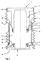
- the single FIGURE shows an inventive air spring device 1 in "overhead position, which here has a lower air spring cover 2, arranged in the upper part air spring piston 3 and an air spring bellows 4.
- the air spring bellows 4 is enclosed by a sleeve-shaped outer guide 5.
- Die Heilfederkolben has an upper connection part 6 for connection eg to a body.
- the air spring bellows 4 is compressed airtight with clamping rings 7 each on clamping seats 8 of the air spring piston 3 and the air spring cover 2 and forms between air spring piston 3 and air spring cover 2 the working space 9 as a volume-elastic cavity, which is acted upon by an overpressure.
- This overpressure ensures that the air spring bellows 4 forms a rolled fold 10 and a further fold 11.
- the roll fold 10 rolls in axial relative movements of air spring piston 3 and air spring cover 2 on the outer circumference of the air spring piston. In the fold 11 rolling on the air spring cover is minimized or completely prevented by a corresponding shape of the lid.
- the air bag 4 is supported on the cover side by a mold ring 12, so that it does not roll or not too strong on the air spring cover 2.
- the overpressure in the working space 9 also presses the air spring bellows 4 from the inside against the outer guide 5.
- the air spring bellows 4 is thereby supported, so that its radial extent does not exceed the predetermined by the outer guide 5 and the spring characteristic significantly determining degree.
- the air spring is provided with a bellows 13 which protects the rolled fold 10 from contamination.
- the bellows 13 is attached to the rolling fold 10 opposite end of the rolling piston 3 with a sealed against impurities crimping clamp 14, surrounds the outer guide 5 by its entire length and goes beyond that, namely extends to the end of the air spring cover. 2
- the bellows 13 is additionally attached via an outwardly projecting collar 15 of the outer guide 5 to the latter.
- the collar 15 has ventilation holes 16.
- the bellows 13 has, in the region of the outer guide 5, a cylindrical section 17 without folds, which assumes a certain guidance of the bellows 13 on the outer guide 5.
- the inner diameter of the bellows in the cylindrical portion is slightly larger than the outer diameter of the outer guide. 5
Landscapes
- Engineering & Computer Science (AREA)
- General Engineering & Computer Science (AREA)
- Mechanical Engineering (AREA)
- Fluid-Damping Devices (AREA)
- Sealing Devices (AREA)
- Diaphragms And Bellows (AREA)
Description
Die Erfindung betrifft eine Luftfedereinrichtung mit einem zwischen einem Luftfederdeckel und einem Luftfeder-Abrollkolben luftdicht eingespannten Luftfederbalg aus elastomerem Material, wobei der Luftfederbalg unter Ausbildung einer Rollfalte am Luftfederkolben abrollt und unter Ausbildung einer zweiten Falte am Luftfederdeckel befestigt ist, mit einer den Luftfederbalg hülsenförmig umfassenden Außenführung.The invention relates to an air spring device with a between an air spring cover and an air spring rolling piston airtight clamped air spring bellows made of elastomeric material, the air bag rolls to form a roll fold on the air spring piston and is attached to form a second fold on the air spring cover, with a bellows comprehensive outside air duct ,
Luftfedereinrichtungen, auch kurz Luftfedern genannt, die zwischen Fahrwerk und Karosserie eingespannt sind und die einen Luftfederbalg aufweisen, der wiederum zwischen einem Luftfederdeckel und einem Abrollkolben befestigt ist, sind in eine Vielzahl von Ausführungen bekannt. Die Luftfeder steht im Betrieb unter einem inneren Überdruck. Der Luftfederbalg rollt unter Last und bei Federbewegungen unter Bildung einer Rollfalte auf der Außenkontur des konzentrischen Luftfederkolbens/Abrollkolbens ab. Eine derartige Luftfeder wird häufig in Straßen- oder Schienenfahrzeugen eingesetzt, um eine komfortable Federung zu erreichen.Air spring devices, also called short air springs, which are clamped between the chassis and body and having an air spring bellows, which in turn is mounted between an air spring cover and a rolling piston are known in a variety of designs. The air spring is in operation under an internal overpressure. The air spring bellows rolls under load and during spring movements to form a rolling fold on the outer contour of the concentric air spring piston / rolling piston from. Such air spring is often used in road or rail vehicles to achieve a comfortable suspension.
Dabei existieren sowohl Luftfedern, bei denen der Luftfederbalg nur einseitig eine Rollfalte bildet, nämlich in der Regel auf dem Abrollkolben, oder Luftfedern, bei denen der Rollbalg unter Bildung einer beidseitigen (Roll-)Falte zwischen Luftfederdeckel und Abrollkolben eingespannt ist. Luftfedern mit einseitiger Rollfalte sind oft in Pkw zu finden, während die oft größeren und tragfähigeren Luftfedern mit beidseitiger Rollfalte eher in LKW und Schienenfahrzeuge eingebaut werden.In this case, there are both air springs in which the air bag forms only one side of a rolling fold, namely usually on the rolling piston, or air springs, in which the rolling bellows is clamped to form a two-sided (rolling) fold between the air spring cover and rolling piston. Air springs with unilateral roll folds are often found in passenger cars, while the often larger and more sustainable air springs with roll creases on both sides are more likely to be installed in trucks and rail vehicles.
Um bei dünneren Rollbälgen eine genügende Tragfähigkeit des Gesamtsystems zu erreichen, werden die Rollbälge bzw. die Luftfedern oder -dämpfer mit so genannten Außenführungen zu versehen, nämlich mit einer den Rollbalg umgebenden rohrförmigen Hülse als "Stützkorsett" oder Stützkörper. So lässt sich beispielsweise ein dünner Rollbalg mit einer dünnen Leichtmetallhülse als Stützkörper auf hohe Innendrücke und damit hohe Tragfähigkeiten bei gleichzeitig gutem Harshness -Verhalten optimieren. Die Außenführungen sind dabei so ausgebildet und angeordnet, dass der Rollbalg einerseits an der Außenseite des Abrollkolbens und andererseits an der Innenoberfläche der Außenführung abrollen kann.In order to achieve a sufficient load-bearing capacity of the overall system for thinner roller bellows, the rolling bellows or the air springs or dampers are provided with so-called outer guides, namely with a tubular sleeve surrounding the rolling bellows as a "supporting corset" or supporting body. Thus, for example, a thin rolling bellows with a thin light metal sleeve as a supporting body can be optimized for high internal pressures and thus high load-bearing capacities combined with good harshness behavior. The outer guides are designed and arranged so that the rolling bellows can roll on the one hand on the outside of the rolling piston and on the other hand on the inner surface of the outer guide.
Insbesondere dann, wenn Luftfedern im Fahrwerksbereich von Fahrzeugen angeordnet sind, werden oft Faltenbälge eingesetzt, die die Luftfeder teilweise umgeben und mit denen z.B. die gegenüber Verschmutzungen empfindliche Rollfalte geschützt wird. Fremdkörper, wie etwa kleine hochgeschleuderte Steine oder Teerstücke aus dem Straßenbelag, können die Gummihaut der Rollbalgfalte nämlich erheblich schädigen und die Lebensdauer verringern.In particular, when air springs are arranged in the chassis area of vehicles, bellows are often used, which partially surround the air spring and with which, for example. protected against soiling sensitive roll fold is protected. Foreign objects, such as small stones thrown up or tarmac from the road surface, can significantly damage the rubber skin of the rolling bellows fold and reduce the service life.
Der Einsatz solcher Faltenbälge birgt keine besonderen Probleme, solange bei relativ großzügigen Bauhöhen Luftfedern mit integrierten und koaxial angeordneten Dämpfern verwendet werden können und für die Luftfeder die übliche Einbaulage vorgesehen ist, bei sich der nämlich der Luftfederdeckel oben und der Abrollkolben unten befinden. Dabei zeigt die Rollfalte "nach unten". Ein Faltenbalg kann dann leicht am unteren Ende der als Außenführung dienenden Hülse und nach unten hin am Dämpfer befestigt werden. Eine solche Befestigung am Dämpfer erlaubt eine ausreichende und die Elastizität des Faltenbalges nicht überdehnende "Arbeitslänge".The use of such bellows holds no special problems, as long as air springs can be used with integrated and coaxial dampers at relatively generous heights and the usual mounting position is provided for the air spring, namely at the top of the air spring cover and the rolling piston are below. The roll fold shows "downwards". A bellows can then be easily attached to the lower end of serving as an outer guide sleeve and down to the damper. Such attachment to the damper allows sufficient and the elasticity of the bellows not overstretching "working length".
Aufgrund des vorhandenen geringen Bauraumes bei modernen Fahrzeugen ist es jedoch oft nötig, Luftfedern ohne integrierte Dämpfer in Über-Kopf-Lage einzubauen. Die Dämpfer werden dann z.B. separat neben der Luftfeder eingebaut, was die "Bauhöhe" des Fahrwerks natürlich erheblich reduzieren kann. Bei dieser auch unter dem Begriff "upside-down-Einbau" bekannten Einbaulage stützt sich der Abrollkolben - nach oben gelegen - an der Karosserie ab, während der Luftfederdeckel unten auf z.B. einem Querlenker einer Achse aufliegt. In dieser Einbaulage ist die Rollfalte nach oben gerichtet und es bildet sich zwischen Außenführung und Abrollkolben ein Ringspalt, also eine ringförmige "Tasche", die unbedingt durch einen Faltenbalg verschlossen werden muss, da sich sonst sofort Fremdkörper in dieser Tasche sammeln und nicht wieder durch die Schwerkraft herausfallen können.Due to the small space available in modern vehicles, however, it is often necessary to install air springs without integrated dampers in an overhead position. The dampers are then replaced e.g. installed separately next to the air spring, which of course can significantly reduce the "height" of the chassis. In this installation position, which is also known by the term "upside-down installation", the rolling piston is supported on the bodywork, while the air spring cover is mounted on the bottom of e.g. a wishbone of an axle rests. In this installation position, the roll fold is directed upwards and forms an annular gap between the outer guide and rolling piston, so an annular "pocket", which must necessarily be closed by a bellows, otherwise immediately foreign objects collect in this bag and not again through the Gravity can fall out.
Eine derartige, gattungsgemäße Luftfeder ist beispielsweise aus der
Weiter beschreibt die
Aufgabe der Erfindung war es nun, für eine solche in Über-Kopf-Lage eingebaute Luftfeder eine Anordnung und Befestigung eines Faltenbalges bereitzustellen, mit der ein zuverlässiger Schutz gegen Verschmutzung erreicht werden kann und die durch die Bereitstellung einer ausreichenden Arbeitslänge für den Faltenbalg letzterem eine sichere Funktion und lange Lebensdauer gewährt.The object of the invention was therefore to provide for such an in-head position built-in air spring arrangement and attachment of a bellows, with a reliable protection against pollution can be achieved and the latter by providing a sufficient working length for the bellows latter a safe Function and long service life granted.
Gelöst wird diese Aufgabe durch die Merkmale des Hauptanspruchs. Weitere vorteilhafte Ausbildungen sind in den Unteransprüchen offenbart.This object is achieved by the features of the main claim. Further advantageous embodiments are disclosed in the subclaims.
Dadurch dass der Faltenbalg einerseits am Ende des Abrollkolbens und andererseits an der Außenführung befestigt ist, ergibt sich eine sichere Fixierung über die Länge des Faltenbalges.The fact that the bellows is fastened on the one hand at the end of the rolling piston and on the other hand on the outer guide, there is a secure fixation over the length of the bellows.
Eine vorteilhafte und besonders einfache zu montierende Ausbildung der Befestigung besteht darin, dass der Faltenbalg am Ende des Abrollkolbens eine gegen Verunreinigungen dichtende Befestigung aufweist, z. B. eine Schraub- oder Quetschschelle, die sicher gegen eindringendes Wasser oder gegen eindringenden Schmutz dichtet.An advantageous and particularly simple to be mounted training the attachment is that the bellows at the end of the rolling piston has a sealing against contamination attachment, z. As a screw or crimp, which seals securely against ingress of water or against ingress of dirt.
Bei einem die Außenführung über im Wesentlichen ihre gesamte Länge umgebenden Faltenbalg ist es vorteilhaft, dass der Faltenbalg am dem Ende oder in der Nähe des Endes der Außenführung befestigt ist, welches dem Luftfederdeckel zugewandt ist.In a bellows surrounding the outer guide over substantially its entire length, it is advantageous that the bellows is secured to the end or near the end of the outer guide, which faces the air spring cover.
Eine weitere vorteilhafte Ausbildung besteht darin, dass der Faltenbalg an der Außenführung eine Befestigung aufweist, die eine Belüftung des vom Faltenbalg umgebenen Raumes erlaubt. Damit kann ein Aufblähen oder Kollabieren des nun doch relativ langen Faltenbalges sicher vermieden werden.A further advantageous embodiment is that the bellows on the outer guide has a fastening that allows ventilation of the space surrounded by the bellows. As a result, inflation or collapse of the now relatively long bellows can be reliably avoided.
Besonders sicher und einfach herzustellende und damit vorteilhafte Ausbildung einer solchen Belüftung und Befestigung an der Außenführung bestehen darin, dass der Faltenbalg an einem nach außen ragenden Kragen oder Vorsprung der Außenführung befestigt ist und der Kragen oder Vorsprung Lüftungsbohrungen aufweist, oder dass der Kragen oder Vorsprung über den Umfang Unterbrechungen oder Ausnehmungen, so genannte "Taschen" aufweist.Particularly safe and easy to manufacture and thus advantageous formation of such ventilation and attachment to the outer guide is that the bellows is attached to an outwardly projecting collar or projection of the outer guide and the collar or projection has ventilation holes, or that the collar or projection over the circumference has interruptions or recesses, so-called "pockets".
Erfindungsgemäß ist der Faltenbalg im Bereich der Außenführung mindestens einen zylindrischen Abschnitt ohne Falten aufweist. Ein solcher zylindrischer Abschnitt übernimmt dann eine gewisse Führung des Faltenbalges auf der Außenführung (Hülse), wodurch verhindert wird, dass beim Einfedern die Enden der Außenführung gegen die Innenseite der Falten laufen. Dies kann nämlich insbesondere dann auftreten, wenn die Außenführung aufgrund der Achskinematik auch zu seitlichen Bewegungen bzw. zu seitlichem Versatz gezwungen ist.According to the invention, the bellows has at least one cylindrical section without folds in the region of the outer guide. Such a cylindrical portion then takes over a certain guidance of the bellows on the outer guide (sleeve), which prevents the ends of the outer guide from running during compression against the inside of the folds. This can occur, in particular, when the outer guide is forced to lateral movements or lateral offset due to the axle kinematics.
Vorteilhafterweise weist der zylindrische Abschnitt des Faltenbalgs dann einen geringfügig größeren Durchmesser als die Außenführung auf, d.h. einen geringfügig größeren Innendurchmesser als der Außendurchmesser der Außenführung.Advantageously, then the cylindrical portion of the bellows then has a slightly larger diameter than the outer guide, i. a slightly larger inner diameter than the outer diameter of the outer guide.
Weiter erfindungsgemäß erstreckt sich der Faltenbalg bis zum Luftfederdeckel. Damit bietet sich eine kostengünstige Möglichkeit, auch den unteren Bereich des Luftfederbalges vor Verschmutzungen zu schützen. Soweit ein vollständige Kapselung gewünscht ist, ist es dabei vorteilhaft, wenn der Faltenbalg am Luftfederdeckel "schmutz- und wasserdicht" befestigt ist, ggf. unter Bereitstellung einer weiteren Belüftung.Further according to the invention, the bellows extends to the air spring cover. This offers a cost-effective way to protect the lower part of the air spring bellows from contamination. As far as complete encapsulation is desired, it is advantageous if the bellows on the air spring cover "dirt and waterproof" is attached, possibly providing a further ventilation.
Die einzige Figur zeigt eine erfindungsgemäße Luftfedereinrichtung 1 in "Über-Kopf-Lage, die hier einen unten angeordneten Luftfederdeckel 2, einen im oberen Teil angeordneten Luftfederkolben 3 und einen Luftfederbalg 4 aufweist. Der Luftfederbalg 4 ist von einer hülsenförmigen Außenführung 5 umschlossen. Der Luftfederkolben weist ein oberes Anschlussteil 6 auf zur Anbindung z. B. an eine Karosserie.The single FIGURE shows an inventive
Der Luftfederbalg 4 ist mit Klemmringen 7 jeweils auf Klemmsitzen 8 des Luftfederkolbens 3 und des Luftfederdeckels 2 luftdicht verpresst und bildet zwischen Luftfederkolben 3 und Luftfederdeckel 2 den Arbeitsraum 9 als volumenelastischen Hohlraum, der mit einem Überdruck beaufschlagbar ist. Dieser Überdruck sorgt dafür, dass der Luftfederbalg 4 eine Rollfalte 10 und eine weitere Falte 11 bildet. Die Rollfalte 10 rollt bei axialen Relativbewegungen von Luftfederkolben 3 und Luftfederdeckel 2 auf dem Außenumfang des Luftfederkolbens ab. Bei der Falte 11 wird ein Abrollen am Luftfederdeckel durch eine entsprechende Formgebung des Deckels minimiert bzw. ganz verhindert. Dazu ist der Luftfederbalg 4 deckelseitig durch einen Formring 12 gestützt, so dass er nicht oder nicht zu stark über den Luftfederdeckel 2 abrollt. Der Überdruck im Arbeitsraum 9 presst außerdem den Luftfederbalg 4 von Innen gegen die Außenführung 5.The air spring bellows 4 is compressed airtight with clamping rings 7 each on clamping seats 8 of the
Der Luftfederbalg 4 wird dadurch gestützt, so dass seine radiale Ausdehnung das durch die Außenführung 5 vorgegebene und die Federcharakteristik erheblich bestimmende Maß nicht überschreitet.The air spring bellows 4 is thereby supported, so that its radial extent does not exceed the predetermined by the outer guide 5 and the spring characteristic significantly determining degree.
Die Luftfeder ist mit einem Faltenbalg 13 versehen, welcher die Rollfalte 10 vor Verschmutzungen schützt. Der Faltenbalg 13 ist an dem der Rollfalte 10 gegenüberliegenden Ende des Abrollkolbens 3 mit einer gegen Verunreinigungen dichtenden Quetschschelle 14 befestigt, umgibt die Außenführung 5 um ihre gesamte Länge und geht noch darüber hinaus, erstreckt sich nämlich bis zum Ende des Luftfederdeckels 2.The air spring is provided with a
Der Faltenbalg 13 ist zusätzlich über einen nach außen ragenden Kragen 15 der Außenführung 5 an letzterer befestigt. Der Kragen 15 weist Lüftungsbohrungen 16 auf.The
Der Faltenbalg 13 weist im Bereich der Außenführung 5 einen zylindrischen Abschnitt 17 ohne Falten auf, der eine gewisse Führung des Faltenbalges 13 auf der Außenführung 5 übernimmt. Der Innendurchmesser des Faltenbalges in dem zylindrischen Abschnitt ist geringfügig größer als der Außendurchmesser der Außenführung 5.The
- 11
- LuftfedereinrichtungAir spring device
- 22
- LuftfederdeckelAir spring cover
- 33
- LuftfederkolbenAir spring piston
- 44
- Luftfederbalgsuspension bellows
- 55
- Außenführungexternal guide
- 66
- AnschussteilAnschussteil
- 77
- Klemmringclamping ring
- 88th
- Klemmsitzforce fit
- 99
- Arbeitsraumworking space
- 1010
- Rollfalterolling fold
- 1111
- Faltewrinkle
- 1212
- Formringmold ring
- 1313
- Faltenbalgbellow
- 1414
- QuetschschelleQuetschschelle
- 1515
- Kragencollar
- 1616
- Lüftungsbohrungventilation hole
- 1717
- Zylindrischer AbschnittCylindrical section
Claims (5)
- Air spring device (1) in the overhead position having an air spring bellows (4) which is made from elastomeric material and is clamped in an airtight manner between an air spring cover (2) and an air spring rolling piston (3), the air spring bellows (4) rolling on the air spring rolling piston (3) with the formation of a rolling fold (10) which is directed upward and being fastened to the air spring cover (2) with the formation of a second fold (11), having an outer guide (5) which encloses the air spring bellows (4) in a sleeve-shaped manner, wherein a folding bellows (13) which protects the rolling fold (10) which is directed upward against contaminants is fastened to that end of the air spring rolling piston (3) which lies opposite the rolling fold (10) and to that end of the outer guide (5) which faces the air spring cover (2),
wherein the folding bellows (13) comprises a section which, away from the air spring rolling piston (3), surrounds the outer guide (5) about its entire length and, moreover, extends to the end of the air spring cover (2), wherein the folding bellows (13) is fastened to the air spring cover (2), wherein the folding bellows (13), in the region of the outer guide (5), has at least one cylindrical section (17) without folds, which takes over guidance of the folding bellows (13) on the outer guide (5), which prevents the ends of the outer guide (5) running against the inner sides of the folds during compression if the outer guide (5) is also forced into lateral movements on account of the axle kinematics, in which the folding bellows (13) is fastened to an outwardly protruding collar or projection (15) of the outer guide (5), and the collar or projection (15) has ventilating holes (16). - Air spring device according to Claim 1, in which the folding bellows (13) has a fastening (14) which seals against contaminants at the end of the rolling piston (3).
- Air spring device according to either of Claims 1 and 2, in which the folding bellows (13) has a fastening on the outer guide (5), which fastening permits ventilation of the space which is surrounded by the folding bellows (13).
- Air spring device according to one of Claims 1 to 3, in which the folding bellows (13) is fastened to an outwardly protruding collar or projection (15) of the outer guide (5), and the collar or projection (15) has interruptions or recesses over the circumference.
- Air spring device according to one of Claims 1 to 4, in which the cylindrical section (17) of the folding bellows (13) has a slightly larger diameter than the outer guide (5).
Applications Claiming Priority (2)
| Application Number | Priority Date | Filing Date | Title |
|---|---|---|---|
| DE102009003829.9A DE102009003829B4 (en) | 2009-04-27 | 2009-04-27 | Air suspension device |
| PCT/EP2010/051836 WO2010124885A1 (en) | 2009-04-27 | 2010-02-15 | Air spring device |
Publications (3)
| Publication Number | Publication Date |
|---|---|
| EP2425147A1 EP2425147A1 (en) | 2012-03-07 |
| EP2425147B1 EP2425147B1 (en) | 2013-04-17 |
| EP2425147B2 true EP2425147B2 (en) | 2016-11-16 |
Family
ID=42133640
Family Applications (1)
| Application Number | Title | Priority Date | Filing Date |
|---|---|---|---|
| EP10704806.8A Active EP2425147B2 (en) | 2009-04-27 | 2010-02-15 | Air spring device |
Country Status (5)
| Country | Link |
|---|---|
| US (1) | US8979076B2 (en) |
| EP (1) | EP2425147B2 (en) |
| CN (1) | CN102449344B (en) |
| DE (1) | DE102009003829B4 (en) |
| WO (1) | WO2010124885A1 (en) |
Families Citing this family (22)
| Publication number | Priority date | Publication date | Assignee | Title |
|---|---|---|---|---|
| WO2012171038A2 (en) * | 2011-06-10 | 2012-12-13 | Conaway, Richard | Air spring with constrained elastic sleeve |
| CN202402545U (en) * | 2012-01-20 | 2012-08-29 | 喜临门家具股份有限公司 | Gas pressure spring with adjustable elastic force |
| EP2870378B1 (en) | 2012-07-03 | 2022-04-13 | Continental Teves AG & Co. OHG | Air spring strut |
| US9387741B2 (en) * | 2012-09-30 | 2016-07-12 | Firestone Industrial Products Company, Llc | Elastomeric thermal barrier as well as gas spring assembly and suspension system including same |
| DE102013004850B4 (en) * | 2013-03-05 | 2018-03-29 | Iwis Motorsysteme Gmbh & Co. Kg | Clamping device with leaf spring diaphragm |
| DE102013211666A1 (en) * | 2013-06-20 | 2014-12-24 | Continental Teves Ag & Co. Ohg | air spring |
| GB2529714B (en) * | 2014-09-01 | 2018-03-28 | Jaguar Land Rover Ltd | Dust boot for a damper of a vehicle suspension system |
| WO2017059476A1 (en) * | 2015-10-06 | 2017-04-13 | Rkc Holdings Pty Ltd | Airbag protection sleeve |
| DE102015119579B4 (en) * | 2015-11-12 | 2021-08-12 | Dunlop Systems And Components | Air suspension unit |
| DE102016202642A1 (en) * | 2016-01-29 | 2017-08-03 | Continental Teves Ag & Co. Ohg | Air spring with bellows |
| US9890829B2 (en) | 2016-04-14 | 2018-02-13 | Air Spring Protection Systems, LLC | Protective sheet for vehicle suspension systems and method of installation thereof |
| US10442266B2 (en) * | 2016-12-05 | 2019-10-15 | Continental Automotive Systems, Inc. | Air spring standing piston bearing |
| EP3372864B1 (en) | 2017-03-07 | 2019-09-11 | Continental Teves AG & Co. OHG | Air spring with a bellows-type connection |
| US10053180B1 (en) * | 2017-08-31 | 2018-08-21 | Tower Trikes, Inc. | Trike steering and suspension systems |
| WO2019143563A1 (en) | 2018-01-19 | 2019-07-25 | Firestone Industrial Products Company, Llc | Gas spring assemblies and methods of assembling same |
| DE102019203368B4 (en) * | 2019-03-12 | 2022-09-29 | Volkswagen Aktiengesellschaft | Protective tube for a vibration damper, vibration damper for a motor vehicle wheel suspension with a protective tube and method for mounting a protective tube |
| US11401994B2 (en) * | 2019-11-08 | 2022-08-02 | Continental Automotive Systems, Inc. | Air spring gaiters with floating ring |
| DE102021103856A1 (en) | 2021-02-18 | 2022-08-18 | Vibracoustic Se | Air spring and vehicle comprising the air spring |
| DE102022210872A1 (en) * | 2022-10-13 | 2024-04-18 | Continental Automotive Technologies GmbH | Air suspension system |
| DE102022129266B3 (en) | 2022-11-07 | 2023-12-28 | Dr. Ing. H.C. F. Porsche Aktiengesellschaft | Device for decoupling in an air suspension of a vehicle, method for producing the device |
| CN116838743A (en) * | 2023-06-30 | 2023-10-03 | 大陆汽车电子系统(常熟)有限公司 | Dustproof assembly, air spring and vehicle |
| DE102024201405B4 (en) * | 2024-02-15 | 2026-03-26 | Aumovio Germany Gmbh | Method for widening a protective bellows of a motor vehicle air spring |
Citations (13)
| Publication number | Priority date | Publication date | Assignee | Title |
|---|---|---|---|---|
| DE1505315A1 (en) † | 1965-07-13 | 1969-10-30 | Berliet Automobiles | Membrane or diaphragm cushion for the pneumatic suspension of motor vehicles or the like., In particular for commercial vehicles |
| EP0944486B1 (en) † | 1996-12-17 | 2002-09-25 | Phoenix Aktiengesellschaft | Pneumatic suspension system |
| DE10323332A1 (en) † | 2003-05-23 | 2004-12-09 | Bayerische Motoren Werke Ag | Pneumatic spring for spring-mounted wheel suspensions of motor vehicle chassis frame, comprises a flexible guide cylinder which is preferably an elastomer hose |
| US20050253316A1 (en) † | 2004-05-13 | 2005-11-17 | Ingo Harms | Air spring device |
| DE102004007962B4 (en) † | 2004-02-18 | 2006-06-14 | Zf Friedrichshafen Ag | Air spring with a protective sleeve for a rolling bellows |
| DE102005045804A1 (en) † | 2005-09-24 | 2007-03-29 | Continental Aktiengesellschaft | A gas spring assembly |
| DE102006005459A1 (en) † | 2006-02-07 | 2007-08-09 | Continental Aktiengesellschaft | Air spring with external guide |
| WO2007124923A1 (en) † | 2006-04-29 | 2007-11-08 | Daimler Ag | Spring shock absorber for a motor vehicle |
| JP2007309357A (en) † | 2006-05-16 | 2007-11-29 | Toyota Motor Corp | Air spring and suspension using the air spring |
| DE102006046560A1 (en) † | 2006-09-30 | 2008-04-03 | Bayerische Motoren Werke Ag | Air spring, in particular for the chassis of a vehicle |
| JP2008082468A (en) † | 2006-09-28 | 2008-04-10 | Bridgestone Corp | Air spring |
| DE102007004037A1 (en) † | 2007-01-22 | 2008-07-31 | Carl Freudenberg Kg | Arrangement for bellows as dust boot at air spring or air spring absorber, has free standing cross layer bellows, and other bellows that is fixed with its ends at exterior side of cross layer bellows of roll folding area |
| JP2009063014A (en) † | 2007-09-04 | 2009-03-26 | Bridgestone Corp | Air spring |
Family Cites Families (10)
| Publication number | Priority date | Publication date | Assignee | Title |
|---|---|---|---|---|
| US4200269A (en) * | 1977-12-08 | 1980-04-29 | Ludwig George C | Self adjusting shock absorber |
| DE3815967A1 (en) | 1987-05-21 | 1988-12-01 | Volkswagen Ag | Oscillation damper with gas- or liquid-filled spaces |
| JPH0237011A (en) * | 1988-07-26 | 1990-02-07 | Mazda Motor Corp | Suspension device |
| DE3934821A1 (en) * | 1989-10-19 | 1991-04-25 | Daimler Benz Ag | Air spring for heavy vehicle - incorporates height adjustable stop to lower suspension for loading and unloading |
| JP2002531784A (en) * | 1998-12-03 | 2002-09-24 | フェニックス アクチエンゲゼルシャフト | Air spring device |
| DE10200632B4 (en) * | 2002-01-10 | 2004-05-27 | Thyssenkrupp Bilstein Gmbh | Air spring strut |
| EP1344957B1 (en) * | 2002-03-13 | 2005-10-05 | Continental Aktiengesellschaft | Pneumatic suspension and damping device |
| DE102004050189A1 (en) * | 2004-10-15 | 2006-04-20 | Contitech Luftfedersysteme Gmbh | air spring |
| DE102006038523A1 (en) | 2006-04-29 | 2007-10-31 | Daimlerchrysler Ag | Spring damping unit for a vehicle comprises a rolling piston which is able slide through a housing part using a sealing element |
| DE102006052314B4 (en) * | 2006-11-07 | 2024-09-12 | Continental Automotive Technologies GmbH | Air suspension system |
-
2009
- 2009-04-27 DE DE102009003829.9A patent/DE102009003829B4/en active Active
-
2010
- 2010-02-15 WO PCT/EP2010/051836 patent/WO2010124885A1/en not_active Ceased
- 2010-02-15 US US13/266,508 patent/US8979076B2/en not_active Expired - Fee Related
- 2010-02-15 EP EP10704806.8A patent/EP2425147B2/en active Active
- 2010-02-15 CN CN201080022892.5A patent/CN102449344B/en not_active Expired - Fee Related
Patent Citations (13)
| Publication number | Priority date | Publication date | Assignee | Title |
|---|---|---|---|---|
| DE1505315A1 (en) † | 1965-07-13 | 1969-10-30 | Berliet Automobiles | Membrane or diaphragm cushion for the pneumatic suspension of motor vehicles or the like., In particular for commercial vehicles |
| EP0944486B1 (en) † | 1996-12-17 | 2002-09-25 | Phoenix Aktiengesellschaft | Pneumatic suspension system |
| DE10323332A1 (en) † | 2003-05-23 | 2004-12-09 | Bayerische Motoren Werke Ag | Pneumatic spring for spring-mounted wheel suspensions of motor vehicle chassis frame, comprises a flexible guide cylinder which is preferably an elastomer hose |
| DE102004007962B4 (en) † | 2004-02-18 | 2006-06-14 | Zf Friedrichshafen Ag | Air spring with a protective sleeve for a rolling bellows |
| US20050253316A1 (en) † | 2004-05-13 | 2005-11-17 | Ingo Harms | Air spring device |
| DE102005045804A1 (en) † | 2005-09-24 | 2007-03-29 | Continental Aktiengesellschaft | A gas spring assembly |
| DE102006005459A1 (en) † | 2006-02-07 | 2007-08-09 | Continental Aktiengesellschaft | Air spring with external guide |
| WO2007124923A1 (en) † | 2006-04-29 | 2007-11-08 | Daimler Ag | Spring shock absorber for a motor vehicle |
| JP2007309357A (en) † | 2006-05-16 | 2007-11-29 | Toyota Motor Corp | Air spring and suspension using the air spring |
| JP2008082468A (en) † | 2006-09-28 | 2008-04-10 | Bridgestone Corp | Air spring |
| DE102006046560A1 (en) † | 2006-09-30 | 2008-04-03 | Bayerische Motoren Werke Ag | Air spring, in particular for the chassis of a vehicle |
| DE102007004037A1 (en) † | 2007-01-22 | 2008-07-31 | Carl Freudenberg Kg | Arrangement for bellows as dust boot at air spring or air spring absorber, has free standing cross layer bellows, and other bellows that is fixed with its ends at exterior side of cross layer bellows of roll folding area |
| JP2009063014A (en) † | 2007-09-04 | 2009-03-26 | Bridgestone Corp | Air spring |
Also Published As
| Publication number | Publication date |
|---|---|
| CN102449344A (en) | 2012-05-09 |
| EP2425147A1 (en) | 2012-03-07 |
| US20120112392A1 (en) | 2012-05-10 |
| US8979076B2 (en) | 2015-03-17 |
| DE102009003829B4 (en) | 2020-08-06 |
| EP2425147B1 (en) | 2013-04-17 |
| DE102009003829A1 (en) | 2010-10-28 |
| WO2010124885A1 (en) | 2010-11-04 |
| CN102449344B (en) | 2016-04-27 |
Similar Documents
| Publication | Publication Date | Title |
|---|---|---|
| EP2425147B2 (en) | Air spring device | |
| EP2870378B1 (en) | Air spring strut | |
| DE10122796B4 (en) | Piston-cylinder unit with a bellows | |
| EP3011198B1 (en) | Air spring | |
| EP2605923B1 (en) | Air strut with elastic piston mounting | |
| EP1188000A1 (en) | Pneumatic suspension system | |
| EP2847487B1 (en) | Air spring and method for turning up an air spring bellows of an air spring | |
| DE102013206235A1 (en) | Air spring, in particular for vehicles | |
| EP2673529B1 (en) | Air spring strut for a vehicle | |
| EP2003363A2 (en) | Pneumatic spring device | |
| DE102011001495B4 (en) | Active air spring damper module | |
| DE102010036365A1 (en) | Air spring roll with partial stiffening | |
| DE102011003151A1 (en) | Pneumatic spring unit for e.g. passenger car, has covering fastened at external periphery and outside upper rolling region of spring rolling bellows by clamping ring, which produces circulating constriction at spring rolling bellows | |
| DE102006005459A1 (en) | Air spring with external guide | |
| DE102021103856A1 (en) | Air spring and vehicle comprising the air spring | |
| DE102014208298B4 (en) | Cuff for a strut module of a vehicle as well as strut module and correspondingly equipped vehicle | |
| EP2218594A1 (en) | Torsion bearing for pneumatic spring | |
| EP2287491B1 (en) | Pneumatic spring | |
| DE102012220754B4 (en) | Air spring | |
| DE202010008268U1 (en) | Air spring device with rolling contour | |
| DE102011109670B4 (en) | air spring | |
| EP2381126B1 (en) | Air spring with double rolling lobe | |
| DE202010008057U1 (en) | Air spring with bellows | |
| DE102018210535B4 (en) | Attaching a damper cap to a damper tube | |
| DE19933783A1 (en) | Protective component for car hydraulic systems has thin-walled elastic hose between which can be moved from position in which lower fastening section is inside higher to position where they are spaced apart |
Legal Events
| Date | Code | Title | Description |
|---|---|---|---|
| PUAI | Public reference made under article 153(3) epc to a published international application that has entered the european phase |
Free format text: ORIGINAL CODE: 0009012 |
|
| 17P | Request for examination filed |
Effective date: 20111128 |
|
| AK | Designated contracting states |
Kind code of ref document: A1 Designated state(s): AT BE BG CH CY CZ DE DK EE ES FI FR GB GR HR HU IE IS IT LI LT LU LV MC MK MT NL NO PL PT RO SE SI SK SM TR |
|
| DAX | Request for extension of the european patent (deleted) | ||
| GRAP | Despatch of communication of intention to grant a patent |
Free format text: ORIGINAL CODE: EPIDOSNIGR1 |
|
| GRAS | Grant fee paid |
Free format text: ORIGINAL CODE: EPIDOSNIGR3 |
|
| GRAA | (expected) grant |
Free format text: ORIGINAL CODE: 0009210 |
|
| AK | Designated contracting states |
Kind code of ref document: B1 Designated state(s): AT BE BG CH CY CZ DE DK EE ES FI FR GB GR HR HU IE IS IT LI LT LU LV MC MK MT NL NO PL PT RO SE SI SK SM TR |
|
| REG | Reference to a national code |
Ref country code: GB Ref legal event code: FG4D Free format text: NOT ENGLISH |
|
| REG | Reference to a national code |
Ref country code: CH Ref legal event code: EP |
|
| REG | Reference to a national code |
Ref country code: IE Ref legal event code: FG4D Free format text: LANGUAGE OF EP DOCUMENT: GERMAN |
|
| REG | Reference to a national code |
Ref country code: AT Ref legal event code: REF Ref document number: 607501 Country of ref document: AT Kind code of ref document: T Effective date: 20130515 |
|
| REG | Reference to a national code |
Ref country code: DE Ref legal event code: R096 Ref document number: 502010002983 Country of ref document: DE Effective date: 20130613 |
|
| REG | Reference to a national code |
Ref country code: LT Ref legal event code: MG4D |
|
| REG | Reference to a national code |
Ref country code: NL Ref legal event code: VDEP Effective date: 20130417 |
|
| PG25 | Lapsed in a contracting state [announced via postgrant information from national office to epo] |
Ref country code: ES Free format text: LAPSE BECAUSE OF FAILURE TO SUBMIT A TRANSLATION OF THE DESCRIPTION OR TO PAY THE FEE WITHIN THE PRESCRIBED TIME-LIMIT Effective date: 20130728 Ref country code: SI Free format text: LAPSE BECAUSE OF FAILURE TO SUBMIT A TRANSLATION OF THE DESCRIPTION OR TO PAY THE FEE WITHIN THE PRESCRIBED TIME-LIMIT Effective date: 20130417 Ref country code: PT Free format text: LAPSE BECAUSE OF FAILURE TO SUBMIT A TRANSLATION OF THE DESCRIPTION OR TO PAY THE FEE WITHIN THE PRESCRIBED TIME-LIMIT Effective date: 20130819 Ref country code: FI Free format text: LAPSE BECAUSE OF FAILURE TO SUBMIT A TRANSLATION OF THE DESCRIPTION OR TO PAY THE FEE WITHIN THE PRESCRIBED TIME-LIMIT Effective date: 20130417 Ref country code: GR Free format text: LAPSE BECAUSE OF FAILURE TO SUBMIT A TRANSLATION OF THE DESCRIPTION OR TO PAY THE FEE WITHIN THE PRESCRIBED TIME-LIMIT Effective date: 20130718 Ref country code: LT Free format text: LAPSE BECAUSE OF FAILURE TO SUBMIT A TRANSLATION OF THE DESCRIPTION OR TO PAY THE FEE WITHIN THE PRESCRIBED TIME-LIMIT Effective date: 20130417 Ref country code: NO Free format text: LAPSE BECAUSE OF FAILURE TO SUBMIT A TRANSLATION OF THE DESCRIPTION OR TO PAY THE FEE WITHIN THE PRESCRIBED TIME-LIMIT Effective date: 20130717 Ref country code: IS Free format text: LAPSE BECAUSE OF FAILURE TO SUBMIT A TRANSLATION OF THE DESCRIPTION OR TO PAY THE FEE WITHIN THE PRESCRIBED TIME-LIMIT Effective date: 20130817 Ref country code: SE Free format text: LAPSE BECAUSE OF FAILURE TO SUBMIT A TRANSLATION OF THE DESCRIPTION OR TO PAY THE FEE WITHIN THE PRESCRIBED TIME-LIMIT Effective date: 20130417 |
|
| PG25 | Lapsed in a contracting state [announced via postgrant information from national office to epo] |
Ref country code: LV Free format text: LAPSE BECAUSE OF FAILURE TO SUBMIT A TRANSLATION OF THE DESCRIPTION OR TO PAY THE FEE WITHIN THE PRESCRIBED TIME-LIMIT Effective date: 20130417 Ref country code: BG Free format text: LAPSE BECAUSE OF FAILURE TO SUBMIT A TRANSLATION OF THE DESCRIPTION OR TO PAY THE FEE WITHIN THE PRESCRIBED TIME-LIMIT Effective date: 20130717 Ref country code: CY Free format text: LAPSE BECAUSE OF FAILURE TO SUBMIT A TRANSLATION OF THE DESCRIPTION OR TO PAY THE FEE WITHIN THE PRESCRIBED TIME-LIMIT Effective date: 20130417 Ref country code: PL Free format text: LAPSE BECAUSE OF FAILURE TO SUBMIT A TRANSLATION OF THE DESCRIPTION OR TO PAY THE FEE WITHIN THE PRESCRIBED TIME-LIMIT Effective date: 20130417 Ref country code: HR Free format text: LAPSE BECAUSE OF FAILURE TO SUBMIT A TRANSLATION OF THE DESCRIPTION OR TO PAY THE FEE WITHIN THE PRESCRIBED TIME-LIMIT Effective date: 20130417 |
|
| PLBI | Opposition filed |
Free format text: ORIGINAL CODE: 0009260 |
|
| PLAB | Opposition data, opponent's data or that of the opponent's representative modified |
Free format text: ORIGINAL CODE: 0009299OPPO |
|
| PG25 | Lapsed in a contracting state [announced via postgrant information from national office to epo] |
Ref country code: CZ Free format text: LAPSE BECAUSE OF FAILURE TO SUBMIT A TRANSLATION OF THE DESCRIPTION OR TO PAY THE FEE WITHIN THE PRESCRIBED TIME-LIMIT Effective date: 20130417 Ref country code: EE Free format text: LAPSE BECAUSE OF FAILURE TO SUBMIT A TRANSLATION OF THE DESCRIPTION OR TO PAY THE FEE WITHIN THE PRESCRIBED TIME-LIMIT Effective date: 20130417 Ref country code: SK Free format text: LAPSE BECAUSE OF FAILURE TO SUBMIT A TRANSLATION OF THE DESCRIPTION OR TO PAY THE FEE WITHIN THE PRESCRIBED TIME-LIMIT Effective date: 20130417 Ref country code: DK Free format text: LAPSE BECAUSE OF FAILURE TO SUBMIT A TRANSLATION OF THE DESCRIPTION OR TO PAY THE FEE WITHIN THE PRESCRIBED TIME-LIMIT Effective date: 20130417 |
|
| 26 | Opposition filed |
Opponent name: TRELLEBORGVIBRACOUSTIC GMBH Effective date: 20140102 |
|
| R26 | Opposition filed (corrected) |
Opponent name: TRELLEBORGVIBRACOUSTIC GMBH Effective date: 20140102 |
|
| PLAX | Notice of opposition and request to file observation + time limit sent |
Free format text: ORIGINAL CODE: EPIDOSNOBS2 |
|
| PG25 | Lapsed in a contracting state [announced via postgrant information from national office to epo] |
Ref country code: NL Free format text: LAPSE BECAUSE OF FAILURE TO SUBMIT A TRANSLATION OF THE DESCRIPTION OR TO PAY THE FEE WITHIN THE PRESCRIBED TIME-LIMIT Effective date: 20130417 Ref country code: IT Free format text: LAPSE BECAUSE OF FAILURE TO SUBMIT A TRANSLATION OF THE DESCRIPTION OR TO PAY THE FEE WITHIN THE PRESCRIBED TIME-LIMIT Effective date: 20130417 Ref country code: RO Free format text: LAPSE BECAUSE OF FAILURE TO SUBMIT A TRANSLATION OF THE DESCRIPTION OR TO PAY THE FEE WITHIN THE PRESCRIBED TIME-LIMIT Effective date: 20130417 |
|
| REG | Reference to a national code |
Ref country code: DE Ref legal event code: R026 Ref document number: 502010002983 Country of ref document: DE Effective date: 20140102 |
|
| PLBB | Reply of patent proprietor to notice(s) of opposition received |
Free format text: ORIGINAL CODE: EPIDOSNOBS3 |
|
| BERE | Be: lapsed |
Owner name: CONTINENTAL TEVES A.G. & CO. OHG Effective date: 20140228 |
|
| PG25 | Lapsed in a contracting state [announced via postgrant information from national office to epo] |
Ref country code: MC Free format text: LAPSE BECAUSE OF FAILURE TO SUBMIT A TRANSLATION OF THE DESCRIPTION OR TO PAY THE FEE WITHIN THE PRESCRIBED TIME-LIMIT Effective date: 20130417 Ref country code: LU Free format text: LAPSE BECAUSE OF FAILURE TO SUBMIT A TRANSLATION OF THE DESCRIPTION OR TO PAY THE FEE WITHIN THE PRESCRIBED TIME-LIMIT Effective date: 20140215 |
|
| REG | Reference to a national code |
Ref country code: CH Ref legal event code: PL |
|
| GBPC | Gb: european patent ceased through non-payment of renewal fee |
Effective date: 20140215 |
|
| PG25 | Lapsed in a contracting state [announced via postgrant information from national office to epo] |
Ref country code: LI Free format text: LAPSE BECAUSE OF NON-PAYMENT OF DUE FEES Effective date: 20140228 Ref country code: CH Free format text: LAPSE BECAUSE OF NON-PAYMENT OF DUE FEES Effective date: 20140228 |
|
| REG | Reference to a national code |
Ref country code: IE Ref legal event code: MM4A |
|
| PG25 | Lapsed in a contracting state [announced via postgrant information from national office to epo] |
Ref country code: IE Free format text: LAPSE BECAUSE OF NON-PAYMENT OF DUE FEES Effective date: 20140215 Ref country code: BE Free format text: LAPSE BECAUSE OF NON-PAYMENT OF DUE FEES Effective date: 20140228 Ref country code: GB Free format text: LAPSE BECAUSE OF NON-PAYMENT OF DUE FEES Effective date: 20140215 |
|
| REG | Reference to a national code |
Ref country code: FR Ref legal event code: PLFP Year of fee payment: 7 |
|
| PG25 | Lapsed in a contracting state [announced via postgrant information from national office to epo] |
Ref country code: MT Free format text: LAPSE BECAUSE OF FAILURE TO SUBMIT A TRANSLATION OF THE DESCRIPTION OR TO PAY THE FEE WITHIN THE PRESCRIBED TIME-LIMIT Effective date: 20130417 |
|
| REG | Reference to a national code |
Ref country code: AT Ref legal event code: MM01 Ref document number: 607501 Country of ref document: AT Kind code of ref document: T Effective date: 20150215 |
|
| PG25 | Lapsed in a contracting state [announced via postgrant information from national office to epo] |
Ref country code: SM Free format text: LAPSE BECAUSE OF FAILURE TO SUBMIT A TRANSLATION OF THE DESCRIPTION OR TO PAY THE FEE WITHIN THE PRESCRIBED TIME-LIMIT Effective date: 20130417 |
|
| PG25 | Lapsed in a contracting state [announced via postgrant information from national office to epo] |
Ref country code: AT Free format text: LAPSE BECAUSE OF NON-PAYMENT OF DUE FEES Effective date: 20150215 |
|
| PG25 | Lapsed in a contracting state [announced via postgrant information from national office to epo] |
Ref country code: TR Free format text: LAPSE BECAUSE OF FAILURE TO SUBMIT A TRANSLATION OF THE DESCRIPTION OR TO PAY THE FEE WITHIN THE PRESCRIBED TIME-LIMIT Effective date: 20130417 Ref country code: HU Free format text: LAPSE BECAUSE OF FAILURE TO SUBMIT A TRANSLATION OF THE DESCRIPTION OR TO PAY THE FEE WITHIN THE PRESCRIBED TIME-LIMIT; INVALID AB INITIO Effective date: 20100215 |
|
| PUAH | Patent maintained in amended form |
Free format text: ORIGINAL CODE: 0009272 |
|
| STAA | Information on the status of an ep patent application or granted ep patent |
Free format text: STATUS: PATENT MAINTAINED AS AMENDED |
|
| 27A | Patent maintained in amended form |
Effective date: 20161116 |
|
| AK | Designated contracting states |
Kind code of ref document: B2 Designated state(s): AT BE BG CH CY CZ DE DK EE ES FI FR GB GR HR HU IE IS IT LI LT LU LV MC MK MT NL NO PL PT RO SE SI SK SM TR |
|
| REG | Reference to a national code |
Ref country code: DE Ref legal event code: R102 Ref document number: 502010002983 Country of ref document: DE |
|
| REG | Reference to a national code |
Ref country code: FR Ref legal event code: PLFP Year of fee payment: 8 |
|
| PG25 | Lapsed in a contracting state [announced via postgrant information from national office to epo] |
Ref country code: LV Free format text: LAPSE BECAUSE OF FAILURE TO SUBMIT A TRANSLATION OF THE DESCRIPTION OR TO PAY THE FEE WITHIN THE PRESCRIBED TIME-LIMIT Effective date: 20161116 |
|
| REG | Reference to a national code |
Ref country code: FR Ref legal event code: PLFP Year of fee payment: 9 |
|
| PG25 | Lapsed in a contracting state [announced via postgrant information from national office to epo] |
Ref country code: MK Free format text: LAPSE BECAUSE OF FAILURE TO SUBMIT A TRANSLATION OF THE DESCRIPTION OR TO PAY THE FEE WITHIN THE PRESCRIBED TIME-LIMIT Effective date: 20130417 |
|
| PGFP | Annual fee paid to national office [announced via postgrant information from national office to epo] |
Ref country code: FR Payment date: 20200219 Year of fee payment: 11 |
|
| PG25 | Lapsed in a contracting state [announced via postgrant information from national office to epo] |
Ref country code: FR Free format text: LAPSE BECAUSE OF NON-PAYMENT OF DUE FEES Effective date: 20210228 |
|
| REG | Reference to a national code |
Ref country code: DE Ref legal event code: R081 Ref document number: 502010002983 Country of ref document: DE Owner name: CONTINENTAL AUTOMOTIVE TECHNOLOGIES GMBH, DE Free format text: FORMER OWNER: CONTINENTAL TEVES AG & CO. OHG, 60488 FRANKFURT, DE Ref country code: DE Ref legal event code: R081 Ref document number: 502010002983 Country of ref document: DE Owner name: AUMOVIO GERMANY GMBH, DE Free format text: FORMER OWNER: CONTINENTAL TEVES AG & CO. OHG, 60488 FRANKFURT, DE |
|
| P01 | Opt-out of the competence of the unified patent court (upc) registered |
Effective date: 20230522 |
|
| REG | Reference to a national code |
Ref country code: DE Ref legal event code: R081 Ref document number: 502010002983 Country of ref document: DE Owner name: CONTINENTAL AUTOMOTIVE TECHNOLOGIES GMBH, DE Free format text: FORMER OWNER: CONTINENTAL AUTOMOTIVE TECHNOLOGIES GMBH, 30165 HANNOVER, DE Ref country code: DE Ref legal event code: R081 Ref document number: 502010002983 Country of ref document: DE Owner name: AUMOVIO GERMANY GMBH, DE Free format text: FORMER OWNER: CONTINENTAL AUTOMOTIVE TECHNOLOGIES GMBH, 30165 HANNOVER, DE |
|
| PGFP | Annual fee paid to national office [announced via postgrant information from national office to epo] |
Ref country code: DE Payment date: 20250228 Year of fee payment: 16 |
|
| REG | Reference to a national code |
Ref country code: DE Ref legal event code: R081 Ref document number: 502010002983 Country of ref document: DE Owner name: AUMOVIO GERMANY GMBH, DE Free format text: FORMER OWNER: CONTINENTAL AUTOMOTIVE TECHNOLOGIES GMBH, 30175 HANNOVER, DE |