EP2425112B1 - Kühleranordnung, kühler und die kühleranordnung umfassendes fahrzeug - Google Patents
Kühleranordnung, kühler und die kühleranordnung umfassendes fahrzeug Download PDFInfo
- Publication number
- EP2425112B1 EP2425112B1 EP09844107.4A EP09844107A EP2425112B1 EP 2425112 B1 EP2425112 B1 EP 2425112B1 EP 09844107 A EP09844107 A EP 09844107A EP 2425112 B1 EP2425112 B1 EP 2425112B1
- Authority
- EP
- European Patent Office
- Prior art keywords
- cooler
- radiator
- egr
- engine
- egr cooler
- Prior art date
- Legal status (The legal status is an assumption and is not a legal conclusion. Google has not performed a legal analysis and makes no representation as to the accuracy of the status listed.)
- Not-in-force
Links
- 239000002826 coolant Substances 0.000 claims description 54
- 238000001816 cooling Methods 0.000 claims description 44
- 238000011144 upstream manufacturing Methods 0.000 claims description 3
- 238000002955 isolation Methods 0.000 claims description 2
- 239000003570 air Substances 0.000 description 78
- 239000007789 gas Substances 0.000 description 43
- XLYOFNOQVPJJNP-UHFFFAOYSA-N water Substances O XLYOFNOQVPJJNP-UHFFFAOYSA-N 0.000 description 20
- 230000002349 favourable effect Effects 0.000 description 15
- 238000007710 freezing Methods 0.000 description 9
- 230000008014 freezing Effects 0.000 description 9
- 238000002485 combustion reaction Methods 0.000 description 5
- 239000000463 material Substances 0.000 description 4
- 239000000203 mixture Substances 0.000 description 4
- 239000004033 plastic Substances 0.000 description 4
- 229920003023 plastic Polymers 0.000 description 4
- LYCAIKOWRPUZTN-UHFFFAOYSA-N Ethylene glycol Chemical compound OCCO LYCAIKOWRPUZTN-UHFFFAOYSA-N 0.000 description 2
- 230000005540 biological transmission Effects 0.000 description 2
- 230000000903 blocking effect Effects 0.000 description 2
- 238000013021 overheating Methods 0.000 description 2
- 238000004806 packaging method and process Methods 0.000 description 2
- 238000009825 accumulation Methods 0.000 description 1
- 239000012080 ambient air Substances 0.000 description 1
- QVGXLLKOCUKJST-UHFFFAOYSA-N atomic oxygen Chemical compound [O] QVGXLLKOCUKJST-UHFFFAOYSA-N 0.000 description 1
- 239000003054 catalyst Substances 0.000 description 1
- 230000006835 compression Effects 0.000 description 1
- 238000007906 compression Methods 0.000 description 1
- 230000009977 dual effect Effects 0.000 description 1
- 239000000446 fuel Substances 0.000 description 1
- 238000010438 heat treatment Methods 0.000 description 1
- WGCNASOHLSPBMP-UHFFFAOYSA-N hydroxyacetaldehyde Natural products OCC=O WGCNASOHLSPBMP-UHFFFAOYSA-N 0.000 description 1
- 230000010354 integration Effects 0.000 description 1
- 239000007788 liquid Substances 0.000 description 1
- 238000002156 mixing Methods 0.000 description 1
- 239000001301 oxygen Substances 0.000 description 1
- 229910052760 oxygen Inorganic materials 0.000 description 1
Images


Classifications
-
- F—MECHANICAL ENGINEERING; LIGHTING; HEATING; WEAPONS; BLASTING
- F01—MACHINES OR ENGINES IN GENERAL; ENGINE PLANTS IN GENERAL; STEAM ENGINES
- F01P—COOLING OF MACHINES OR ENGINES IN GENERAL; COOLING OF INTERNAL-COMBUSTION ENGINES
- F01P3/00—Liquid cooling
- F01P3/20—Cooling circuits not specific to a single part of engine or machine
-
- F—MECHANICAL ENGINEERING; LIGHTING; HEATING; WEAPONS; BLASTING
- F02—COMBUSTION ENGINES; HOT-GAS OR COMBUSTION-PRODUCT ENGINE PLANTS
- F02B—INTERNAL-COMBUSTION PISTON ENGINES; COMBUSTION ENGINES IN GENERAL
- F02B29/00—Engines characterised by provision for charging or scavenging not provided for in groups F02B25/00, F02B27/00 or F02B33/00 - F02B39/00; Details thereof
- F02B29/04—Cooling of air intake supply
- F02B29/0406—Layout of the intake air cooling or coolant circuit
- F02B29/0437—Liquid cooled heat exchangers
- F02B29/0443—Layout of the coolant or refrigerant circuit
-
- F—MECHANICAL ENGINEERING; LIGHTING; HEATING; WEAPONS; BLASTING
- F02—COMBUSTION ENGINES; HOT-GAS OR COMBUSTION-PRODUCT ENGINE PLANTS
- F02B—INTERNAL-COMBUSTION PISTON ENGINES; COMBUSTION ENGINES IN GENERAL
- F02B29/00—Engines characterised by provision for charging or scavenging not provided for in groups F02B25/00, F02B27/00 or F02B33/00 - F02B39/00; Details thereof
- F02B29/04—Cooling of air intake supply
- F02B29/045—Constructional details of the heat exchangers, e.g. pipes, plates, ribs, insulation, materials, or manufacturing and assembly
- F02B29/0475—Constructional details of the heat exchangers, e.g. pipes, plates, ribs, insulation, materials, or manufacturing and assembly the intake air cooler being combined with another device, e.g. heater, valve, compressor, filter or EGR cooler, or being assembled on a special engine location
-
- F—MECHANICAL ENGINEERING; LIGHTING; HEATING; WEAPONS; BLASTING
- F02—COMBUSTION ENGINES; HOT-GAS OR COMBUSTION-PRODUCT ENGINE PLANTS
- F02M—SUPPLYING COMBUSTION ENGINES IN GENERAL WITH COMBUSTIBLE MIXTURES OR CONSTITUENTS THEREOF
- F02M26/00—Engine-pertinent apparatus for adding exhaust gases to combustion-air, main fuel or fuel-air mixture, e.g. by exhaust gas recirculation [EGR] systems
- F02M26/13—Arrangement or layout of EGR passages, e.g. in relation to specific engine parts or for incorporation of accessories
- F02M26/22—Arrangement or layout of EGR passages, e.g. in relation to specific engine parts or for incorporation of accessories with coolers in the recirculation passage
- F02M26/23—Layout, e.g. schematics
- F02M26/24—Layout, e.g. schematics with two or more coolers
-
- F—MECHANICAL ENGINEERING; LIGHTING; HEATING; WEAPONS; BLASTING
- F02—COMBUSTION ENGINES; HOT-GAS OR COMBUSTION-PRODUCT ENGINE PLANTS
- F02M—SUPPLYING COMBUSTION ENGINES IN GENERAL WITH COMBUSTIBLE MIXTURES OR CONSTITUENTS THEREOF
- F02M26/00—Engine-pertinent apparatus for adding exhaust gases to combustion-air, main fuel or fuel-air mixture, e.g. by exhaust gas recirculation [EGR] systems
- F02M26/13—Arrangement or layout of EGR passages, e.g. in relation to specific engine parts or for incorporation of accessories
- F02M26/22—Arrangement or layout of EGR passages, e.g. in relation to specific engine parts or for incorporation of accessories with coolers in the recirculation passage
- F02M26/23—Layout, e.g. schematics
- F02M26/28—Layout, e.g. schematics with liquid-cooled heat exchangers
-
- F—MECHANICAL ENGINEERING; LIGHTING; HEATING; WEAPONS; BLASTING
- F02—COMBUSTION ENGINES; HOT-GAS OR COMBUSTION-PRODUCT ENGINE PLANTS
- F02M—SUPPLYING COMBUSTION ENGINES IN GENERAL WITH COMBUSTIBLE MIXTURES OR CONSTITUENTS THEREOF
- F02M26/00—Engine-pertinent apparatus for adding exhaust gases to combustion-air, main fuel or fuel-air mixture, e.g. by exhaust gas recirculation [EGR] systems
- F02M26/13—Arrangement or layout of EGR passages, e.g. in relation to specific engine parts or for incorporation of accessories
- F02M26/22—Arrangement or layout of EGR passages, e.g. in relation to specific engine parts or for incorporation of accessories with coolers in the recirculation passage
- F02M26/29—Constructional details of the coolers, e.g. pipes, plates, ribs, insulation or materials
- F02M26/30—Connections of coolers to other devices, e.g. to valves, heaters, compressors or filters; Coolers characterised by their location on the engine
-
- F—MECHANICAL ENGINEERING; LIGHTING; HEATING; WEAPONS; BLASTING
- F28—HEAT EXCHANGE IN GENERAL
- F28D—HEAT-EXCHANGE APPARATUS, NOT PROVIDED FOR IN ANOTHER SUBCLASS, IN WHICH THE HEAT-EXCHANGE MEDIA DO NOT COME INTO DIRECT CONTACT
- F28D21/00—Heat-exchange apparatus not covered by any of the groups F28D1/00 - F28D20/00
- F28D21/0001—Recuperative heat exchangers
- F28D21/0003—Recuperative heat exchangers the heat being recuperated from exhaust gases
-
- F—MECHANICAL ENGINEERING; LIGHTING; HEATING; WEAPONS; BLASTING
- F28—HEAT EXCHANGE IN GENERAL
- F28F—DETAILS OF HEAT-EXCHANGE AND HEAT-TRANSFER APPARATUS, OF GENERAL APPLICATION
- F28F9/00—Casings; Header boxes; Auxiliary supports for elements; Auxiliary members within casings
- F28F9/02—Header boxes; End plates
- F28F9/0202—Header boxes having their inner space divided by partitions
- F28F9/0204—Header boxes having their inner space divided by partitions for elongated header box, e.g. with transversal and longitudinal partitions
- F28F9/0214—Header boxes having their inner space divided by partitions for elongated header box, e.g. with transversal and longitudinal partitions having only longitudinal partitions
-
- F—MECHANICAL ENGINEERING; LIGHTING; HEATING; WEAPONS; BLASTING
- F28—HEAT EXCHANGE IN GENERAL
- F28F—DETAILS OF HEAT-EXCHANGE AND HEAT-TRANSFER APPARATUS, OF GENERAL APPLICATION
- F28F9/00—Casings; Header boxes; Auxiliary supports for elements; Auxiliary members within casings
- F28F9/02—Header boxes; End plates
- F28F9/0234—Header boxes; End plates having a second heat exchanger disposed there within, e.g. oil cooler
-
- Y—GENERAL TAGGING OF NEW TECHNOLOGICAL DEVELOPMENTS; GENERAL TAGGING OF CROSS-SECTIONAL TECHNOLOGIES SPANNING OVER SEVERAL SECTIONS OF THE IPC; TECHNICAL SUBJECTS COVERED BY FORMER USPC CROSS-REFERENCE ART COLLECTIONS [XRACs] AND DIGESTS
- Y02—TECHNOLOGIES OR APPLICATIONS FOR MITIGATION OR ADAPTATION AGAINST CLIMATE CHANGE
- Y02T—CLIMATE CHANGE MITIGATION TECHNOLOGIES RELATED TO TRANSPORTATION
- Y02T10/00—Road transport of goods or passengers
- Y02T10/10—Internal combustion engine [ICE] based vehicles
- Y02T10/12—Improving ICE efficiencies
Definitions
- the invention relates to a cooler arrangement and a vehicle comprising a cooler arrangement according to the preamble of independent claim 1.
- EGR exhaust gas recirculation
- CAC charge air cooler
- the recirculated exhaust gas is cooled to such a low temperature as possible.
- the lowest temperature is limited by freezing of condensed water in a low temperature EGR cooler (LT-EGR cooler) in a multistage EGR cooling circuit.
- Exhaust gases carry a large amount of water from combustion and intake air.
- the dew point is around 40°C to 60°C.
- Condensing water is not a problem as long as the condensed water is introduced in the combustion process continuously.
- water accumulation of a certain volume during low load operation of the engine which is then introduced into the engine at higher load can damage the engine.
- accumulated water will stay in the LT-EGR cooler when the engine is switched off. In cold ambient, the water can freeze and cause damage besides blocking the LT-EGR cooler.
- Use of a LT-EGR cooler in cold climate can cause not only condensing but also freezing even during operation.
- the inner surface of the heat exchanger in the LT-EGR cooler will be covered by ice which can grow in thickness until the LT-EGR cooler is blocked which will deteriorate the operation of the exhaust emission control system.
- LT-EGR cooler has to be by-passed when ambient temperatures decrease close to the freezing point of water which results in a loss of efficiency of the exhaust emission control.
- the exhaust gas leaving the engine borne high temperature EGR cooler may be cooled in a second step for both single stage and dual stage turbo charged engines.
- the low temperature exhaust gas recirculation can either be cooled by a coolant or directly by the air flow.
- WO 2007/055644 discloses a system for exhaust gas recirculation with a HT-EGR cooler and a LT-EGR cooler.
- the HT-EGR cooler is cooled by a fan whilst the LT-EGR cooler is cooled either by a flow of air or by a separate cooling circuit.
- JP H09 280118 relates to a cooler arrangement where an EGR cooler is arranged in a cooler manifold of a cooler.
- the EGR cooler is arranged in the inlet manifold of a charge air cooler.
- a cooler arrangement for a vehicle is proposed, particularly a commercial vehicle, wherein at least one EGR cooler is arranged in a cooler manifold of a cooler. Integrating the at least one EGR cooler in the cooler manifold is very space efficient.
- the cooler manifold provides space for the at least one EGR cooler.
- a cooler medium is contained in the cooler manifold, for instance a liquid or a gas.
- a cooler manifold is generally arranged at the inlet side (inlet manifold) and the outlet side (outlet manifold) of a cooler.
- the cooler medium commonly also called coolant, is distributed from the inlet manifold to channels in the cooler and collected in the outlet manifold.
- the cooler medium is used in a cooling circuit, for instance as engine coolant and the like.
- a cooling medium preferably air in an incoming air flow
- the cooler medium used to cool the EGR cooler can be controlled with respect to temperature.
- a favourably low temperature can be achieved without the danger of freezing and subsequently blocking the passage for the exhaust gases through the EGR.
- the cooling can be controlled via the cooler medium down to temperatures close to the freezing point of water, e.g. down to 5°C or even lower, without the risk of uncontrolled freezing of water contained in the exhaust gases.
- the cooler medium can be a conventional water/glycol-mixture or gas, e.g. air which is used in a cooling circuit. In a charge air cooler, for instance, the cooler medium can be the charged air.
- the at least one EGR cooler can be arranged in a housing of a radiator.
- the EGR cooler can be immersed in the cooler medium of the radiator in a manifold of the radiator.
- the at least one EGR cooler can be arranged in a housing of a charge air cooler.
- the EGR cooler can be immersed in the cooler medium contained in a cooler manifold of the charge air cooler.
- the at least one EGR cooler can be arranged in a higher position than an inlet manifold of an engine, which is operationally connected to the EGR cooler.
- the term "higher position" defines a position above the inlet manifold in a height direction of a vehicle when the cooler arrangement is arranged in the vehicle.
- the inlet manifold of the engine is provided for feeding air into the combustion engine.
- Water condensing in the EGR cooler can flow continuously into the engine without the possibility to accumulate in pockets between the EGR cooler and the inlet manifold of the engine.
- the power efficiency of the engine can be improved thus improving the efficiency of fuel usage and reducing emissions.
- the water can be sprayed into the compression stroke of the engine thus cooling the vapour which results in an increase of power of the engine.
- the at least one EGR cooler can be arranged in an outlet manifold of the cooler.
- the cooler medium in the outlet manifold of the cooler has an advantageous low temperature.
- an efficient cooling of the medium to be cooled in the at least one EGR cooler can be provided.
- the outlet manifold is usually arranged at the topmost part of the radiator, thus allowing condensed water in the EGR cooler to flow to the engine instead of accumulating.
- the at least one EGR cooler can be arranged in an intermediate manifold of the cooler.
- the cooler is embodied as radiator when the radiator is of the back-to-front type with the inlet and outlet manifolds at one side of the radiator, e.g. at the bottom, and the intermediate manifold at the opposite side, e.g. the top of the radiator.
- the intermediate manifold is usually arranged at the topmost part of the radiator, thus allowing water to flow to the engine instead of accumulating in the piping.
- the at least one cooler can be a low temperature radiator.
- the cooler can be kept at an expediently low temperature level which is available in the cooling circuit of the vehicle.
- the cooler can operate in a temperature range below 200°C.
- the temperature of the medium, e.g. exhaust gas, cooled in at least one EGR cooler can be reduced in a high temperature stage to a reasonable value below 200°C, preferably not more than 150°C.
- a conventional plastic material can be used for the radiator manifold.
- the at least one EGR cooler can be arranged upstream of a charge air cooler with respect to the exhaust gas flow in the multistage cooling circuit.
- This is an expedient arrangement for a cooling circuit of a combustion engine.
- a connection pipe between the at least one EGR cooler and the charge air cooler can be favourably short.
- placing the at least one EGR cooler close to the charge air cooler allows for using a hose connected to the charge air cooler for mixing the recirculated exhaust evacuating from the at least one EGR cooler and the fresh air evacuating from the charge air cooler.
- the cooler can be a full face radiator.
- full face defines that the extent of the radiator in a plane perpendicular to a longitudinal direction of the vehicle substantially covers an opening in the front of an engine compartment when viewed in a longitudinal direction of the vehicle.
- the charge air cooler can be arranged at the rear of the engine.
- the cooler can be a non-full-face radiator.
- non-full face defines that the extent of the radiator in a plane perpendicular to a longitudinal direction of the vehicle is substantially smaller than the extent of an opening in the front of an engine compartment in said plane perpendicular to the longitudinal direction of the vehicle.
- the radiator can be located adjacent a charge air cooler. After being cooled in the at least one EGR cooler integrated in a manifold of the radiator, the exhaust gases need to travel only a very short distance, e.g. a few centimetres or a few millimetres, to the charge air cooler outlet manifold, where the exhaust gas is mixed with fresh compressed air.
- the cooler medium used for cooling the at least one EGR cooler need not to be routed back to the engine, only back to the radiator inlet manifold. If the radiator cooler medium is only used for cooling the at least one EGR cooler integrated in the radiator housing, e.g. in the radiator outlet manifold, no cooler medium from this circuit needs to be routed back to the engine. If the radiator cooler medium is employed for cooling one or more additional components than the at least one EGR cooler, e.g. for transmission cooling, hoses and pipes routed to the engine can have a smaller diameter than otherwise.
- the cooler can provide a separator for thermal isolation of the at least one EGR cooler and a portion of the coolant circulating in the cooler.
- cold cooler medium which is meant for other cooling purposes than the at least one EGR cooler is not in thermal contact with the at least one cooler and consequently not heated up unintentionally.
- a cooler for a vehicle comprising a cooler housing, wherein an EGR cooler is arranged in the cooler housing.
- the cooler constitutes a space efficient component for a multistage cooling circuit employed for an engine such as a combustion engine.
- the EGR cooler can be arranged in a cooler manifold of the radiator.
- the cooler medium of the radiator the temperature of which is controllable, can be used as cooler medium for cooling the EGR cooler. Freezing of water in the EGR cooler can be avoided.
- the EGR cooler can be arranged in the cooler outlet manifold.
- the cooler medium in the outlet manifold is at the lowest temperature available in the cooler and can be used to cool the at least one cooler.
- a vehicle comprising a cooler arrangement comprising at least one radiator and one or more coolers.
- At least one EGR cooler is arranged in a cooler housing of a cooler.
- the at least one EGR cooler can constitute a stage of a multistage cooling circuit for cooling a medium in more than one stages. Integrating the at least one EGR cooler in the cooler, e.g. a radiator or a charge air cooler, is very space efficient and allows for a controlled cooling of the EGR cooler. Freezing at low temperatures in the EGR cooler can be avoided.
- the at least one EGR cooler is effectively and in a controlled way cooled by the cooler medium.
- the vehicle can preferably be a truck, such as a heavy duty, a medium duty or a light duty truck.
- a space efficient multistage cooling circuit by way of example an exhaust gas recirculation cooling circuit, can be provided.
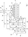
- Fig. 1 depicts schematically a first embodiment of a cooler arrangement 100 for a vehicle 200 ( Fig. 6 ) comprising a multistage cooling circuit 130 for exhaust gas recirculation (EGR) with an engine 10.
- the multistage cooling circuit 130 has a high temperature EGR cooler 30 (HT EGR cooler 30) arranged at the outlet manifold 14 of the engine 10 and a low temperature EGR cooler 40 (LT-EGR cooler 40) integrated in an outlet manifold 74 of a low temperature radiator 70 (LT radiator 70).
- the low temperature radiator is configured for a temperature up to about 10-15°C above an ambient temperature, i.e. rarely above 50°C.
- the LT radiator 70 has a coolant circuit 80.
- a pump 82 circulates the cooler medium through the LT radiator 70.
- the cooler medium is also often called “coolant”.
- the cooler medium can be an engine coolant, particularly water/glycol mixture, or charged air in a charge air cooler or the like.
- the manifold 74 is often called "
- a portion of the exhaust gas from the engine 10 is fed through a pipe 32 into the HT-EGR cooler 30, whereas another portion of the exhaust gas is directly fed into an exhaust line 18 (bypassing the HT EGR cooler) and transferred into a catalyst section 26 via a turbine 24 of a turbocharger 20.
- a compressor 22 of the turbocharger 20 in the air feed pipe 66 compressed fresh air which is cooled in a charge air cooler 60.
- the cooled air is fed to an inlet manifold 12 of the engine 10 through an output pipe 68. Cooled exhaust is fed into the output pipe 68 and mixed with the fresh air.
- the LT radiator 70 is by way of example a non-full-face radiator as it is arranged adjacent to (beside) the charge air cooler 60. Both together constitute the foremost area of the cooling package in front of the engine 10.
- An engine coolant cools the exhaust gas in the HT-EGR cooler 30.
- the engine coolant is fed through pipe 52 to a radiator 50 as cooler medium and cooled coolant, i.e. cooled cooler medium, through pipe 54 back to the engine 10.
- a part of the engine coolant can flow through the HT-EGR cooler 30 and through pipe 16 and is mixed with the engine coolant in pipe 52.
- a coolant pump 92 in pipe 54 circulates the coolant. Air is sucked into the engine compartment via a fan 90 downstream of the radiator 50.
- the radiator 50 can be by-passed by the engine coolant through a by-pass pipe 56.
- the coolant flow can be split by a valve 58 located in the input pipe 52.
- Exhaust gas which is cooled in the HT-EGR cooler 30 is fed back to the inlet manifold 12 of the engine and the air pipe 68, respectively, through a recirculation pipe 34.
- exhaust gas is cooled below 200°C in the HT-EGR cooler 30.
- a valve 36 in the recirculation pipe 34 can feed a portion of the precooled exhaust gas to the LT-EGR cooler 40 through a feed pipe 38. After cooling further down, the portion of the exhaust gas is fed into the air pipe 68 upstream of the exhaust gas directly originating from the HT-EGR cooler 30.
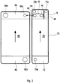
- Fig. 2a illustrates a part of a second embodiment of the cooler arrangement not included in the scope of protection. More specifically, Fig. 2a illustrates a back view of a non-full-face LT radiator 70 with a housing 78 and an outlet manifold 74 encompassing the LT-EGR cooler 40, adjacent to the charge air cooler 60.
- the outlet manifold 74 is often called "outlet tank”.
- the LT radiator 70 comprises a tubular system (not shown) comprising a plurality of narrow, spaced tubes extending between an inlet tank 72 and the outlet tank 74 for transporting the coolant, wherein the air sucked into the engine compartment via the fan 90 flows between the tubes.
- Coolant (cooler medium) circulating through the LT radiator 70 is cooled by the wind sucked through the LT radiator 70 by the fan 90 ( Fig. 1 ).
- the cooler medium enters the radiator 70 through a port 70a in an inlet manifold 72 and evacuates the LT radiator 70 through a port 70b in the outlet manifold 74.
- the LT-EGR cooler 40 integrated in the LT radiator 70 is cooled by the coolant of the LT radiator 70. Exhaust gas enters the LT-EGR cooler 40 through port 44 and leaves the LT-EGR cooler through port 46 towards an input port 60c of the charge air cooler 60.
- the LT-EGR cooler 40 may comprise a tubular system (not shown) comprising a plurality of narrow, spaced tubes extending between the port 44 and the port 46 for transporting the exhaust gases, wherein the coolant in the outlet tank cooles the tubes.
- the distance of the connection 42 (shown in Fig. 1 as pipe 42) is favourably very short in the range of only a few centimetres down to a few millimetres.
- the cooling air flows perpendicular to the faces of the charge air cooler 60 and the LT radiator 70, i.e. perpendicular to the paper plane of the drawing.
- Compressed air enters the charge air cooler 60 through a port 60a in an inlet tank 62 of the charge air cooler 60 and leaves the charge air cooler 60 through a port 60b in an outlet manifold 64 of the charge air cooler 60 where it is mixed with the exhaust gas coming from the LT-EGR cooler 40.
- the cooler medium is continuously circulated in the LT radiator 70 in order to avoid overheating of the LT radiator 70 by the precooled exhaust gas.
- FIG. 2b A part of a third embodiment of the cooler arrangement, not included in the scope of protection, with a charge air cooler 60 encompassing an LT-EGR cooler 40 as second cooler can be seen in Fig. 2b .
- Fig. 2c displays a detail of this arrangement.
- the LT-EGR cooler 40 is disposed in the outlet manifold 64 of the charge air cooler 60, wherein the LT-EGR cooler 40 is immersed in a compartment 64a of the outlet manifold 64.
- the LT-EGR cooler 40 can be immersed in a separate coolant, e.g. engine coolant from a low-temperature coolant circuit, indicated by ingoing and outgoing arrows in the compartment 64a.
- the cooled exhaust gas from the LT-EGR cooler 40 is mixed with cooled charge air in the outlet manifold 64 of the charged air cooler 60 and discharged towards the engine through output port 60c.
- the arrangement is compact and space efficient.
- Fig. 3 illustrates a fourth embodiment of the cooler arrangement. More specifically, Fig. 3 illustrates a back view of a non-full-face LT radiator 70 like in Fig. 1 with a housing 78 and an outlet manifold 74 encompassing the LT-EGR cooler 40, adjacent to the charge air cooler 60.
- Cooler medium circulating through the LT radiator 70 is cooled by the wind sucked through the LT radiator 70 by the fan 90 ( Fig. 1 ).
- the cooler medium enters the radiator 70 through a port 70a in the inlet manifold 72 and evacuates the LT radiator 70 through ports 70b and 70c in the outlet manifold 74 which is divided by a separator wall 48 in two compartments. Coolant in the compartment where port 70c is located is virtually not in thermal contact with the LT-EGR cooler 40 which is located in the compartment of port 70b.
- the LT-EGR cooler 40 integrated in the LT radiator 70 is cooled by the cooler medium of the LT radiator 70. Exhaust gas enters the LT-EGR cooler 40 through port 44 and leaves the LT-EGR cooler through port 46 towards an input port 60c of the charge air cooler 60.
- connection 42 (shown in Fig. 1 as pipe 42) is favourably very short in the range of only a few centimetres down to a few millimetres.
- the cooling air flows perpendicular to the faces of the charge air cooler 60 and the LT radiator 70, i.e. perpendicular to the paper plane of the drawing.
- Compressed air enters the charge air cooler 60 through port 60a in an inlet manifold 62 of the charge air cooler 60 and leaves the charge air cooler 60 through port 60b in an outlet manifold 64 of the charge air cooler 60 where it is mixed with the exhaust gas coming from the LT-EGR cooler 40.
- the cooler medium is continuously circulated in the LT radiator 70 in order to avoid overheating of the LT radiator 70 by the precooled exhaust gas.
- Fig. 4 illustrates a fifth embodiment of the cooler arrangement.
- the cooler arrangement comprises a full-face radiator 70 according to the invention is shown.
- the cooler arrangement 110 comprises a multistage cooling circuit 130 for exhaust gas recirculation (EGR) with an engine 10.
- the multistage cooling circuit 130 has a high temperature EGR cooler 30 (HT EGR cooler 30) arranged at the outlet manifold 14 of the engine 10 and a low temperature EGR cooler 40 (LT-EGR cooler 40) integrated in an outlet manifold 74 of a low temperature radiator 70 (LT radiator 70).
- the LT radiator 70 has a coolant circuit 80.
- the coolant circuit 80 is parallel to a second coolant circuit 96.
- the coolant circuits 80 and 96 are connected by a valve 88.
- the second cooling circuit 96 comprises a pipe 84 from the LT radiator 70 to a charge air cooler 60 arranged at the rear of the engine 10, the charge air cooler 60, a pipe 86 from the charge air cooler 60 to a pump 92 which circulates the coolant in the second coolant circuit 96, and a pipe 83 from the engine 10 to the LT radiator 70.
- the coolant in the second coolant circuit 96 can be mixed with engine coolant fed to the engine 10.
- the engine coolant is cooled in a radiator 50 fed to the engine 10 through an output pipe 54 to which pipe 86 connects.
- An engine coolant cools the exhaust gas in the HT-EGR cooler 30.
- the engine coolant is fed through pipe 52 to a radiator 50 and cooled coolant through pipe 54 back to the engine 10.
- a part of the engine coolant can flow through the HT-EGR cooler 30 and subsequently through pipe 16 and is mixed with the engine coolant in pipe 52.
- a coolant pump 92 in pipe 54 circulates the coolant. Air is sucked into the engine compartment via a fan 90 downstream of the radiator 50.
- the engine coolant can by-pass the radiator 50 through a by-pass pipe 56.
- the coolant flow can be split by a valve 58 located in the input pipe 52.
- An element 94 is arranged between pipe 83 and 86.
- a portion of the exhaust gas from the engine 10 is fed through a pipe 32 into the HT-EGR cooler 30, whereas another portion of the exhaust gas is directly fed into the exhaust line 18 and transferred into a catalyser section 26 via a turbine 24 of a turbocharger 20.
- a compressor 22 of the turbocharger 20 in the air feed pipe 66 compressed fresh air which is cooled in a charge air cooler 60.
- the cooled air is fed to an inlet manifold 12 of the engine 10 through an output pipe 68. Cooled exhaust evacuated from the LT-EGR cooler 40 is fed into the output pipe 68 and mixed with the fresh air.
- the HT-EGR cooler 30 is connected directly to the LT radiator 70 by a pipe 38 and from the LT-EGR cooler 40 back through a pipe 42 to pipe 68 where recirculated and now cooled exhaust gas can be mixed with fresh air and the mixture fed to the inlet manifold 12 of the engine 10 as mentioned above.
- exhaust gas is cooled below 200°C in the HT-EGR cooler 30.
- the LT radiator 70 is a full-face radiator arranged as foremost one of the radiators 40, 50 of the cooling package in front of the engine 10, whereas the charge air cooler 60 is arranged at the rear of the engine.
- Fig. 5 shows a LT radiator 170 in a side view according to a sixth example embodiment of the cooler arrangement not included in the scope of protection.
- the LT radiator 170 can be a full face or a non-full-face device.
- the LT radiator 170 is arranged as of a "back-to-front" type, i.e. the coolant inlet and outlet tanks are on the same side of the radiator housing 178.
- the coolant enters the radiator housing 178 through an inlet tank 172 in the bottom, flows upwards to an intermediate tank 174 and back downwards to the outlet tank 176.
- the flow direction is indicated by arrows in the radiator housing 178.
- the cooling air is indicated by a bold arrow parallel to the paper plane of the drawing.
- a second cooler 40 preferably a LT-EGR cooler 40 is arranged in the intermediate manifold 174 of the LT radiator 170 and cooled by the radiator coolant flowing from the inlet manifold 172 in the bottom to the intermediate manifold 174 in the top and back to the outlet manifold 176 in the bottom.
- a preferred vehicle according to the invention which incorporates a cooler arrangement 100 or 110 which was described in Fig. 1 and Fig. 3 .
- a LT-EGR cooler 40 ( Fig. 1 , Fig. 4 ) can be integrated in an outlet manifold 74 of a LT-radiator 70 ( Figs. 3 , 4 ) or in an intermediate manifold 174 of an LT radiator 170 ( Fig. 5 ).
- the EGR gases may have temperatures of around 150 °C, which means that a plastic manifold 74, 174 can be used for the radiator 70, 170.
- the cooler medium used for LT-EGR cooling does not need to be routed to the engine 10 ( Fig. 1 , Fig. 4 ), only back again to the LT-radiator inlet manifold 72, 172. If the LT radiator coolant is used only for the LT-EGR cooling it is not necessary to rout cooler medium from this circuit to the engine. If the LT radiator cooler medium is used for other purposes as well, e.g. as coolant for cooling a transmission, hoses and pipes routed to the engine 10 ( Fig. 1 , Fig. 4 ) can have smaller diameter than otherwise.
- Integration of the LT-EGR cooler 40 into the LT radiator 70, 170 saves cost and weight. Engine packaging is facilitated, since there is no additional component on the engine 10 such as an engine mounted LT-EGR cooler. Either no LT coolant at all, or a smaller amount of coolant has to be routed to the engine, which once again facilitates packaging.
- the present invention can be implemented on all trucks comprising LT-EGR cooling.
Landscapes
- Engineering & Computer Science (AREA)
- Mechanical Engineering (AREA)
- General Engineering & Computer Science (AREA)
- Chemical & Material Sciences (AREA)
- Combustion & Propulsion (AREA)
- Physics & Mathematics (AREA)
- Thermal Sciences (AREA)
- Exhaust-Gas Circulating Devices (AREA)
Claims (13)
- Kühleranordnung (100, 110) für ein Fahrzeug (200), insbesondere ein Nutzfahrzeug, wobei in der Kühleranordnung (100, 110) wenigstens ein EGR-Kühler (40) in einem Kühler-Sammler (74, 174) eines Kühlers (60, 70, 170) angeordnet ist, dadurch gekennzeichnet, dass der Kühler (60, 70, 170) eine Trenneinrichtung (48) zur thermischen Isolierung des wenigstens einen EGR-Kühlers (40) und eines Abschnitts des in dem Kühler (60, 70, 170) zirkulierenden Kühlmittels bereitstellt.
- Kühleranordnung nach Anspruch 1, dadurch gekennzeichnet, dass der wenigstens eine EGR-Kühler (40) in einem Gehäuse (78, 178) eines Radiators (70, 170) angeordnet ist.
- Kühleranordnung nach Anspruch 1, dadurch gekennzeichnet, dass der wenigstens eine EGR-Kühler (40) in einem Gehäuse eines Ladeluftkühlers (60) angeordnet ist.
- Kühleranordnung nach einem vorhergehenden Anspruch, dadurch gekennzeichnet, dass der wenigstens eine EGR-Kühler (40) eine Niedrigtemperaturstufe eines EGR-Kühl-Kreislaufs (130) zum Kühlen eines Abgases in mehr als einer Stufe darstellt.
- Kühleranordnung nach einem vorhergehenden Anspruch, dadurch gekennzeichnet, dass der wenigstens eine EGR-Kühler (40) an einer höheren Position als ein Einlass-Sammler (12) eines Motors (10) angeordnet ist, der mit dem EGR-Kühler (40) funktionell verbunden ist.
- Kühleranordnung nach einem vorhergehenden Anspruch, dadurch gekennzeichnet, dass der wenigstens eine EGR-Kühler (40) in einem Auslass-Sammler (74) oder einem Zwischen-Sammler (174) des Kühlers (60, 70, 170) angeordnet ist.
- Kühleranordnung nach einem vorhergehenden Anspruch, dadurch gekennzeichnet, dass der Kühler (70, 170) ein Niedrigtemperaturradiator ist.
- Kühleranordnung nach einem vorhergehenden Anspruch, dadurch gekennzeichnet, dass der Kühler (60, 70, 170) in einem Temperaturbereich unter 200°C arbeitet.
- Kühleranordnung nach einem vorhergehenden Anspruch, dadurch gekennzeichnet, dass der wenigstens eine EGR-Kühler (40) stromaufwärts von einem Ladeluftkühler (60) in Bezug auf die Abgasströmung in einem Mehrstufenkühlkreislauf (130) angeordnet ist.
- Kühleranordnung nach einem vorhergehenden Anspruch, dadurch gekennzeichnet, dass der Kühler (70, 170) ein vollflächiger Radiator ist.
- Kühleranordnung nach einem der Ansprüche 1 bis 9, dadurch gekennzeichnet, dass der Kühler (70, 170) ein nicht-vollflächiger Radiator ist.
- Kühleranordnung nach Anspruch 9 und 11, dadurch gekennzeichnet, dass der wenigstens eine Radiator (70, 170) angrenzend an den Ladeluftkühler (60) angeordnet ist.
- Fahrzeug (200), insbesondere Nutzfahrzeug, umfassend eine Kühleranordnung (100, 110) nach einem der Ansprüche 1 bis 12.
Applications Claiming Priority (1)
| Application Number | Priority Date | Filing Date | Title |
|---|---|---|---|
| PCT/SE2009/000221 WO2010126402A1 (en) | 2009-04-28 | 2009-04-28 | Cooler arrangement, a cooler and vehicle comprising the cooler arrangement |
Publications (3)
| Publication Number | Publication Date |
|---|---|
| EP2425112A1 EP2425112A1 (de) | 2012-03-07 |
| EP2425112A4 EP2425112A4 (de) | 2015-12-16 |
| EP2425112B1 true EP2425112B1 (de) | 2017-03-22 |
Family
ID=43032369
Family Applications (1)
| Application Number | Title | Priority Date | Filing Date |
|---|---|---|---|
| EP09844107.4A Not-in-force EP2425112B1 (de) | 2009-04-28 | 2009-04-28 | Kühleranordnung, kühler und die kühleranordnung umfassendes fahrzeug |
Country Status (2)
| Country | Link |
|---|---|
| EP (1) | EP2425112B1 (de) |
| WO (1) | WO2010126402A1 (de) |
Families Citing this family (5)
| Publication number | Priority date | Publication date | Assignee | Title |
|---|---|---|---|---|
| CN105179061B (zh) * | 2015-10-16 | 2018-03-20 | 安徽江淮汽车集团股份有限公司 | 一种包括有双膨胀水箱的双循环冷却系统 |
| CN105179067B (zh) * | 2015-10-16 | 2017-12-22 | 安徽江淮汽车集团股份有限公司 | 一种包括有辅助水泵的双循环冷却系统 |
| CN105201630B (zh) * | 2015-10-16 | 2018-04-06 | 安徽江淮汽车集团股份有限公司 | 一种包括有双膨胀水箱的冷却系统 |
| JP6230585B2 (ja) * | 2015-11-18 | 2017-11-15 | 本田技研工業株式会社 | 内燃機関の排気浄化装置 |
| US10767601B2 (en) * | 2019-01-18 | 2020-09-08 | Volvo Car Corporation | Vehicle exhaust gas recirculation system utilizing a low temperature circuit-high temperature circuit crossover valve assembly |
Family Cites Families (12)
| Publication number | Priority date | Publication date | Assignee | Title |
|---|---|---|---|---|
| US5186245A (en) * | 1992-04-06 | 1993-02-16 | General Motors Corporation | Flow control baffle for radiator in-tank cooler |
| JPH09280118A (ja) | 1996-04-16 | 1997-10-28 | Isuzu Motors Ltd | ディーゼルエンジン用egr装置 |
| BR0307933A (pt) * | 2002-12-03 | 2004-12-21 | Behr Gmbh & Co | Dispositivo para a refrigeração |
| FR2856747B1 (fr) * | 2003-06-25 | 2005-09-23 | Valeo Thermique Moteur Sa | Module de refroidissement de l'air de suralimentation et des gaz d'echappement recircules d'un moteur a combustion interne de vehicule automobile. |
| SE528198C2 (sv) * | 2005-02-21 | 2006-09-26 | Scania Cv Ab | Laddluftkylare |
| SE529101C2 (sv) | 2005-09-20 | 2007-05-02 | Scania Cv Ab | Kylarrangemang för återcirkulation av gaser hos en överladdad förbränningsmotor |
| US7464700B2 (en) * | 2006-03-03 | 2008-12-16 | Proliance International Inc. | Method for cooling an internal combustion engine having exhaust gas recirculation and charge air cooling |
| US7516779B1 (en) * | 2006-03-15 | 2009-04-14 | Proliance International Inc. | Concentric tube oil cooler |
| JP4970022B2 (ja) * | 2006-08-02 | 2012-07-04 | カルソニックカンセイ株式会社 | 複合型熱交換器及び複合型熱交換器システム |
| JP2008106688A (ja) * | 2006-10-26 | 2008-05-08 | Mazda Motor Corp | エンジンの排気環流装置 |
| SE531102C2 (sv) * | 2006-12-05 | 2008-12-16 | Scania Cv Ab | Arrangemang hos en överladdad förbränningsmotor |
| JP2008231941A (ja) * | 2007-03-16 | 2008-10-02 | Toyota Motor Corp | 還流ガスの冷却装置 |
-
2009
- 2009-04-28 EP EP09844107.4A patent/EP2425112B1/de not_active Not-in-force
- 2009-04-28 WO PCT/SE2009/000221 patent/WO2010126402A1/en not_active Ceased
Non-Patent Citations (1)
| Title |
|---|
| None * |
Also Published As
| Publication number | Publication date |
|---|---|
| EP2425112A1 (de) | 2012-03-07 |
| WO2010126402A1 (en) | 2010-11-04 |
| EP2425112A4 (de) | 2015-12-16 |
Similar Documents
| Publication | Publication Date | Title |
|---|---|---|
| US6244256B1 (en) | High-temperature coolant loop for cooled exhaust gas recirculation for internal combustion engines | |
| US8051841B2 (en) | Charging fluid intake module and internal combustion engine | |
| US7254947B2 (en) | Vehicle cooling system | |
| US20060236987A1 (en) | Method for controlling the temperature of gases entering an engine of an automotive vehicle, heat exchanger and device for managing the temperature of these gases | |
| CN102140979B (zh) | 废气再循环系统中的水分清除 | |
| US6935319B2 (en) | Exhaust-gas recirculation system of an internal combustion engine | |
| US8424303B2 (en) | Cooling arrangement for a supercharged internal combustion engine | |
| CN101743390B (zh) | 内燃机 | |
| US9506395B2 (en) | Cooling system and associated operating method | |
| US7757678B2 (en) | Locomotive exhaust gas recirculation cooling | |
| US11125190B2 (en) | Methods and system for an engine system | |
| US20080196679A1 (en) | Cooling System For a Motor Vehicle | |
| EP2425112B1 (de) | Kühleranordnung, kühler und die kühleranordnung umfassendes fahrzeug | |
| US20100006043A1 (en) | Cooling arrangement at a vehicle | |
| EP1819911B1 (de) | Kühlvorrichtung in einem fahrzeug | |
| JP2010511125A (ja) | 車両の冷却器装置 | |
| US20100269800A1 (en) | Exhaust gas recirculation cooling circuit | |
| US9556824B2 (en) | Integration of forced EGR/EGR-pump into EGR-cooler | |
| US8127722B2 (en) | Cooling circuit for the thermal engine of an automotive vehicle | |
| CN105927373B (zh) | 用于发动机组件的歧管 | |
| KR20060034238A (ko) | 가스 온도 조절 방법 및 열교환 시스템 | |
| US20100199664A1 (en) | Device and method for recirculating exhaust gas in an internal combustion engine | |
| US8973538B2 (en) | Inline engine having side-mounted heat exchangers | |
| CN102482980B (zh) | 用于车辆的冷却回路及包括冷却回路的车辆 | |
| KR20150032589A (ko) | 내연기관용 과급 공기 냉각을 위한 시스템 및 과급 공기 냉각을 제공하기 위한 관련 방법 |
Legal Events
| Date | Code | Title | Description |
|---|---|---|---|
| PUAI | Public reference made under article 153(3) epc to a published international application that has entered the european phase |
Free format text: ORIGINAL CODE: 0009012 |
|
| 17P | Request for examination filed |
Effective date: 20111128 |
|
| AK | Designated contracting states |
Kind code of ref document: A1 Designated state(s): AT BE BG CH CY CZ DE DK EE ES FI FR GB GR HR HU IE IS IT LI LT LU LV MC MK MT NL NO PL PT RO SE SI SK TR |
|
| DAX | Request for extension of the european patent (deleted) | ||
| RA4 | Supplementary search report drawn up and despatched (corrected) |
Effective date: 20151113 |
|
| RIC1 | Information provided on ipc code assigned before grant |
Ipc: F02M 25/07 20060101AFI20151109BHEP Ipc: F01P 3/20 20060101ALI20151109BHEP Ipc: F28F 9/02 20060101ALI20151109BHEP Ipc: F28D 21/00 20060101ALN20151109BHEP Ipc: F02B 29/04 20060101ALI20151109BHEP |
|
| GRAP | Despatch of communication of intention to grant a patent |
Free format text: ORIGINAL CODE: EPIDOSNIGR1 |
|
| RIC1 | Information provided on ipc code assigned before grant |
Ipc: F02M 26/28 20160101ALI20160526BHEP Ipc: F01P 3/20 20060101ALI20160526BHEP Ipc: F28F 9/02 20060101ALI20160526BHEP Ipc: F02M 26/24 20160101AFI20160526BHEP Ipc: F02B 29/04 20060101ALI20160526BHEP Ipc: F28D 21/00 20060101ALN20160526BHEP Ipc: F02M 26/30 20160101ALI20160526BHEP |
|
| INTG | Intention to grant announced |
Effective date: 20160609 |
|
| GRAJ | Information related to disapproval of communication of intention to grant by the applicant or resumption of examination proceedings by the epo deleted |
Free format text: ORIGINAL CODE: EPIDOSDIGR1 |
|
| REG | Reference to a national code |
Ref country code: DE Ref legal event code: R079 Ref document number: 602009045015 Country of ref document: DE Free format text: PREVIOUS MAIN CLASS: F02M0025070000 Ipc: F02M0026240000 |
|
| GRAP | Despatch of communication of intention to grant a patent |
Free format text: ORIGINAL CODE: EPIDOSNIGR1 |
|
| INTC | Intention to grant announced (deleted) | ||
| RIC1 | Information provided on ipc code assigned before grant |
Ipc: F02M 26/24 20160101AFI20161013BHEP Ipc: F02B 29/04 20060101ALI20161013BHEP Ipc: F02M 26/28 20160101ALI20161013BHEP Ipc: F02M 26/30 20160101ALI20161013BHEP Ipc: F01P 3/20 20060101ALI20161013BHEP Ipc: F28D 21/00 20060101ALN20161013BHEP Ipc: F28F 9/02 20060101ALI20161013BHEP |
|
| INTG | Intention to grant announced |
Effective date: 20161103 |
|
| GRAS | Grant fee paid |
Free format text: ORIGINAL CODE: EPIDOSNIGR3 |
|
| GRAA | (expected) grant |
Free format text: ORIGINAL CODE: 0009210 |
|
| RIN1 | Information on inventor provided before grant (corrected) |
Inventor name: JEMT, KATARINA Inventor name: DAHL, ERIK |
|
| AK | Designated contracting states |
Kind code of ref document: B1 Designated state(s): AT BE BG CH CY CZ DE DK EE ES FI FR GB GR HR HU IE IS IT LI LT LU LV MC MK MT NL NO PL PT RO SE SI SK TR |
|
| REG | Reference to a national code |
Ref country code: GB Ref legal event code: FG4D |
|
| REG | Reference to a national code |
Ref country code: FR Ref legal event code: PLFP Year of fee payment: 9 |
|
| REG | Reference to a national code |
Ref country code: CH Ref legal event code: EP |
|
| REG | Reference to a national code |
Ref country code: AT Ref legal event code: REF Ref document number: 878048 Country of ref document: AT Kind code of ref document: T Effective date: 20170415 |
|
| REG | Reference to a national code |
Ref country code: IE Ref legal event code: FG4D |
|
| REG | Reference to a national code |
Ref country code: DE Ref legal event code: R096 Ref document number: 602009045015 Country of ref document: DE |
|
| REG | Reference to a national code |
Ref country code: NL Ref legal event code: MP Effective date: 20170322 |
|
| PG25 | Lapsed in a contracting state [announced via postgrant information from national office to epo] |
Ref country code: NO Free format text: LAPSE BECAUSE OF FAILURE TO SUBMIT A TRANSLATION OF THE DESCRIPTION OR TO PAY THE FEE WITHIN THE PRESCRIBED TIME-LIMIT Effective date: 20170622 Ref country code: FI Free format text: LAPSE BECAUSE OF FAILURE TO SUBMIT A TRANSLATION OF THE DESCRIPTION OR TO PAY THE FEE WITHIN THE PRESCRIBED TIME-LIMIT Effective date: 20170322 Ref country code: HR Free format text: LAPSE BECAUSE OF FAILURE TO SUBMIT A TRANSLATION OF THE DESCRIPTION OR TO PAY THE FEE WITHIN THE PRESCRIBED TIME-LIMIT Effective date: 20170322 Ref country code: GR Free format text: LAPSE BECAUSE OF FAILURE TO SUBMIT A TRANSLATION OF THE DESCRIPTION OR TO PAY THE FEE WITHIN THE PRESCRIBED TIME-LIMIT Effective date: 20170623 Ref country code: LT Free format text: LAPSE BECAUSE OF FAILURE TO SUBMIT A TRANSLATION OF THE DESCRIPTION OR TO PAY THE FEE WITHIN THE PRESCRIBED TIME-LIMIT Effective date: 20170322 |
|
| REG | Reference to a national code |
Ref country code: LT Ref legal event code: MG4D |
|
| REG | Reference to a national code |
Ref country code: AT Ref legal event code: MK05 Ref document number: 878048 Country of ref document: AT Kind code of ref document: T Effective date: 20170322 |
|
| PG25 | Lapsed in a contracting state [announced via postgrant information from national office to epo] |
Ref country code: LV Free format text: LAPSE BECAUSE OF FAILURE TO SUBMIT A TRANSLATION OF THE DESCRIPTION OR TO PAY THE FEE WITHIN THE PRESCRIBED TIME-LIMIT Effective date: 20170322 Ref country code: SE Free format text: LAPSE BECAUSE OF FAILURE TO SUBMIT A TRANSLATION OF THE DESCRIPTION OR TO PAY THE FEE WITHIN THE PRESCRIBED TIME-LIMIT Effective date: 20170322 Ref country code: BG Free format text: LAPSE BECAUSE OF FAILURE TO SUBMIT A TRANSLATION OF THE DESCRIPTION OR TO PAY THE FEE WITHIN THE PRESCRIBED TIME-LIMIT Effective date: 20170622 |
|
| PG25 | Lapsed in a contracting state [announced via postgrant information from national office to epo] |
Ref country code: NL Free format text: LAPSE BECAUSE OF FAILURE TO SUBMIT A TRANSLATION OF THE DESCRIPTION OR TO PAY THE FEE WITHIN THE PRESCRIBED TIME-LIMIT Effective date: 20170322 |
|
| PG25 | Lapsed in a contracting state [announced via postgrant information from national office to epo] |
Ref country code: AT Free format text: LAPSE BECAUSE OF FAILURE TO SUBMIT A TRANSLATION OF THE DESCRIPTION OR TO PAY THE FEE WITHIN THE PRESCRIBED TIME-LIMIT Effective date: 20170322 Ref country code: SK Free format text: LAPSE BECAUSE OF FAILURE TO SUBMIT A TRANSLATION OF THE DESCRIPTION OR TO PAY THE FEE WITHIN THE PRESCRIBED TIME-LIMIT Effective date: 20170322 Ref country code: ES Free format text: LAPSE BECAUSE OF FAILURE TO SUBMIT A TRANSLATION OF THE DESCRIPTION OR TO PAY THE FEE WITHIN THE PRESCRIBED TIME-LIMIT Effective date: 20170322 Ref country code: RO Free format text: LAPSE BECAUSE OF FAILURE TO SUBMIT A TRANSLATION OF THE DESCRIPTION OR TO PAY THE FEE WITHIN THE PRESCRIBED TIME-LIMIT Effective date: 20170322 Ref country code: IT Free format text: LAPSE BECAUSE OF FAILURE TO SUBMIT A TRANSLATION OF THE DESCRIPTION OR TO PAY THE FEE WITHIN THE PRESCRIBED TIME-LIMIT Effective date: 20170322 Ref country code: EE Free format text: LAPSE BECAUSE OF FAILURE TO SUBMIT A TRANSLATION OF THE DESCRIPTION OR TO PAY THE FEE WITHIN THE PRESCRIBED TIME-LIMIT Effective date: 20170322 Ref country code: CZ Free format text: LAPSE BECAUSE OF FAILURE TO SUBMIT A TRANSLATION OF THE DESCRIPTION OR TO PAY THE FEE WITHIN THE PRESCRIBED TIME-LIMIT Effective date: 20170322 |
|
| PG25 | Lapsed in a contracting state [announced via postgrant information from national office to epo] |
Ref country code: IS Free format text: LAPSE BECAUSE OF FAILURE TO SUBMIT A TRANSLATION OF THE DESCRIPTION OR TO PAY THE FEE WITHIN THE PRESCRIBED TIME-LIMIT Effective date: 20170722 Ref country code: PL Free format text: LAPSE BECAUSE OF FAILURE TO SUBMIT A TRANSLATION OF THE DESCRIPTION OR TO PAY THE FEE WITHIN THE PRESCRIBED TIME-LIMIT Effective date: 20170322 Ref country code: PT Free format text: LAPSE BECAUSE OF FAILURE TO SUBMIT A TRANSLATION OF THE DESCRIPTION OR TO PAY THE FEE WITHIN THE PRESCRIBED TIME-LIMIT Effective date: 20170724 |
|
| REG | Reference to a national code |
Ref country code: CH Ref legal event code: PL |
|
| REG | Reference to a national code |
Ref country code: DE Ref legal event code: R097 Ref document number: 602009045015 Country of ref document: DE |
|
| REG | Reference to a national code |
Ref country code: IE Ref legal event code: MM4A |
|
| PLBE | No opposition filed within time limit |
Free format text: ORIGINAL CODE: 0009261 |
|
| STAA | Information on the status of an ep patent application or granted ep patent |
Free format text: STATUS: NO OPPOSITION FILED WITHIN TIME LIMIT |
|
| PG25 | Lapsed in a contracting state [announced via postgrant information from national office to epo] |
Ref country code: DK Free format text: LAPSE BECAUSE OF FAILURE TO SUBMIT A TRANSLATION OF THE DESCRIPTION OR TO PAY THE FEE WITHIN THE PRESCRIBED TIME-LIMIT Effective date: 20170322 Ref country code: MC Free format text: LAPSE BECAUSE OF FAILURE TO SUBMIT A TRANSLATION OF THE DESCRIPTION OR TO PAY THE FEE WITHIN THE PRESCRIBED TIME-LIMIT Effective date: 20170322 |
|
| 26N | No opposition filed |
Effective date: 20180102 |
|
| GBPC | Gb: european patent ceased through non-payment of renewal fee |
Effective date: 20170622 |
|
| PG25 | Lapsed in a contracting state [announced via postgrant information from national office to epo] |
Ref country code: SI Free format text: LAPSE BECAUSE OF FAILURE TO SUBMIT A TRANSLATION OF THE DESCRIPTION OR TO PAY THE FEE WITHIN THE PRESCRIBED TIME-LIMIT Effective date: 20170322 Ref country code: LI Free format text: LAPSE BECAUSE OF NON-PAYMENT OF DUE FEES Effective date: 20170430 Ref country code: CH Free format text: LAPSE BECAUSE OF NON-PAYMENT OF DUE FEES Effective date: 20170430 Ref country code: LU Free format text: LAPSE BECAUSE OF NON-PAYMENT OF DUE FEES Effective date: 20170428 |
|
| REG | Reference to a national code |
Ref country code: BE Ref legal event code: MM Effective date: 20170430 |
|
| REG | Reference to a national code |
Ref country code: FR Ref legal event code: PLFP Year of fee payment: 10 |
|
| PG25 | Lapsed in a contracting state [announced via postgrant information from national office to epo] |
Ref country code: GB Free format text: LAPSE BECAUSE OF NON-PAYMENT OF DUE FEES Effective date: 20170622 Ref country code: IE Free format text: LAPSE BECAUSE OF NON-PAYMENT OF DUE FEES Effective date: 20170428 |
|
| PG25 | Lapsed in a contracting state [announced via postgrant information from national office to epo] |
Ref country code: BE Free format text: LAPSE BECAUSE OF NON-PAYMENT OF DUE FEES Effective date: 20170430 |
|
| PG25 | Lapsed in a contracting state [announced via postgrant information from national office to epo] |
Ref country code: MT Free format text: LAPSE BECAUSE OF NON-PAYMENT OF DUE FEES Effective date: 20170428 |
|
| PG25 | Lapsed in a contracting state [announced via postgrant information from national office to epo] |
Ref country code: HU Free format text: LAPSE BECAUSE OF FAILURE TO SUBMIT A TRANSLATION OF THE DESCRIPTION OR TO PAY THE FEE WITHIN THE PRESCRIBED TIME-LIMIT; INVALID AB INITIO Effective date: 20090428 |
|
| PG25 | Lapsed in a contracting state [announced via postgrant information from national office to epo] |
Ref country code: CY Free format text: LAPSE BECAUSE OF NON-PAYMENT OF DUE FEES Effective date: 20170322 |
|
| PG25 | Lapsed in a contracting state [announced via postgrant information from national office to epo] |
Ref country code: MK Free format text: LAPSE BECAUSE OF FAILURE TO SUBMIT A TRANSLATION OF THE DESCRIPTION OR TO PAY THE FEE WITHIN THE PRESCRIBED TIME-LIMIT Effective date: 20170322 |
|
| PG25 | Lapsed in a contracting state [announced via postgrant information from national office to epo] |
Ref country code: TR Free format text: LAPSE BECAUSE OF FAILURE TO SUBMIT A TRANSLATION OF THE DESCRIPTION OR TO PAY THE FEE WITHIN THE PRESCRIBED TIME-LIMIT Effective date: 20170322 |
|
| PGFP | Annual fee paid to national office [announced via postgrant information from national office to epo] |
Ref country code: FR Payment date: 20230421 Year of fee payment: 15 Ref country code: DE Payment date: 20230427 Year of fee payment: 15 |
|
| REG | Reference to a national code |
Ref country code: DE Ref legal event code: R119 Ref document number: 602009045015 Country of ref document: DE |
|
| PG25 | Lapsed in a contracting state [announced via postgrant information from national office to epo] |
Ref country code: DE Free format text: LAPSE BECAUSE OF NON-PAYMENT OF DUE FEES Effective date: 20241105 |
|
| PG25 | Lapsed in a contracting state [announced via postgrant information from national office to epo] |
Ref country code: FR Free format text: LAPSE BECAUSE OF NON-PAYMENT OF DUE FEES Effective date: 20240430 |
|
| PG25 | Lapsed in a contracting state [announced via postgrant information from national office to epo] |
Ref country code: FR Free format text: LAPSE BECAUSE OF NON-PAYMENT OF DUE FEES Effective date: 20240430 Ref country code: DE Free format text: LAPSE BECAUSE OF NON-PAYMENT OF DUE FEES Effective date: 20241105 |