EP2425047B1 - Front-loading household washing machine, in particular a laundry washing or washing/drying machine - Google Patents
Front-loading household washing machine, in particular a laundry washing or washing/drying machine Download PDFInfo
- Publication number
- EP2425047B1 EP2425047B1 EP10723783.6A EP10723783A EP2425047B1 EP 2425047 B1 EP2425047 B1 EP 2425047B1 EP 10723783 A EP10723783 A EP 10723783A EP 2425047 B1 EP2425047 B1 EP 2425047B1
- Authority
- EP
- European Patent Office
- Prior art keywords
- dispenser
- washing
- door
- washing machine
- wash tub
- Prior art date
- Legal status (The legal status is an assumption and is not a legal conclusion. Google has not performed a legal analysis and makes no representation as to the accuracy of the status listed.)
- Not-in-force
Links
Images


Classifications
-
- D—TEXTILES; PAPER
- D06—TREATMENT OF TEXTILES OR THE LIKE; LAUNDERING; FLEXIBLE MATERIALS NOT OTHERWISE PROVIDED FOR
- D06F—LAUNDERING, DRYING, IRONING, PRESSING OR FOLDING TEXTILE ARTICLES
- D06F39/00—Details of washing machines not specific to a single type of machines covered by groups D06F9/00 - D06F27/00
- D06F39/02—Devices for adding soap or other washing agents
-
- D—TEXTILES; PAPER
- D06—TREATMENT OF TEXTILES OR THE LIKE; LAUNDERING; FLEXIBLE MATERIALS NOT OTHERWISE PROVIDED FOR
- D06F—LAUNDERING, DRYING, IRONING, PRESSING OR FOLDING TEXTILE ARTICLES
- D06F39/00—Details of washing machines not specific to a single type of machines covered by groups D06F9/00 - D06F27/00
- D06F39/12—Casings; Tubs
- D06F39/14—Doors or covers; Securing means therefor
-
- D—TEXTILES; PAPER
- D06—TREATMENT OF TEXTILES OR THE LIKE; LAUNDERING; FLEXIBLE MATERIALS NOT OTHERWISE PROVIDED FOR
- D06F—LAUNDERING, DRYING, IRONING, PRESSING OR FOLDING TEXTILE ARTICLES
- D06F37/00—Details specific to washing machines covered by groups D06F21/00 - D06F25/00
- D06F37/26—Casings; Tubs
- D06F37/28—Doors; Security means therefor
Definitions
- the present invention relates to a front-loading household washing machine, in particular a laundry washing or washing/drying machine, according to the preamble of claim 1.
- the invention is applicable to the field of front-loading household washing machines, in particular laundry washing or washing/drying machines, wherein the dispenser of washing agents (detergent, softener, bleach, etc.) is located in the door that closes the load opening of the machine.
- washing agents detergent, softener, bleach, etc.
- a door In front-loading household washing machines known in the art, a door is used for closing the load opening through which the laundry to be washed is placed into a drum rotating inside a wash tub.
- the door usually includes a transparent porthole glass, which allows the user to see the internal portion of the rotary drum and the laundry loaded therein.
- Patent GB2029862 discloses a door for front-loading household washing machines that comprises a porthole glass within which a washing agent dispenser is provided.
- the door and the porthole glass are fitted with a housing wherein an extractable dispenser is inserted, which is shaped like a small basket open on top.
- Document WO 2004/055253 A1 relates to a washing machine door comprising a container for the washing products.
- the upper central part of the glass (6) of the loading door (4) comprises a built-in removable container (7) for the washing products.
- at least one water conduit (8) which is used to convey water the washing products, accesses the aforementioned container (7) through the hinged portion of the door (4) and is guided through the frame (5) of same.
- washing agent dispenser built in the porthole glass may cause a leak of washing agents onto the floor in front of the washing machine, especially when the user pours into the dispenser a quantity of washing agents in excess of the maximum allowable or recommended level. This drawback is particularly critical when liquid detergents or additives are used.
- washing agent dispenser built in the porthole glass does not allow the user to adequately see the internal portion of the rotary drum and the laundry loaded therein.
- washing machines described in the above-mentioned documents oblige the user to take a rather uncomfortable position in order to pour the washing agents into the appropriate dispenser, since the latter is located in a relatively low position.
- the present invention provides a front-loading household washing machine, in particular a laundry washing or washing/drying machine, incorporating the features set out in the annexed claims, which are intended as an integral part of the present description.
- Fig. 1 is a sectional view of a front-loading household washing machine 1, in particular a laundry washing or washing/drying machine, according to the present invention.
- the washing machine 1 comprises a cabinet 2 within which a wash tub 3 is arranged in a known manner. Inside the latter, a drum 4 is rotated about a horizontal or substantially horizontal axis X.
- the laundry to be washed is placed inside the drum 4 through a load opening 5 associated with a front part 21 of the cabinet 2.
- the axis X of the drum 4 is preferably slightly inclined, in that it is raised towards the front part 21 of the cabinet; this allows a user to load the laundry into the drum 4 more easily.
- the load opening 5 is closed by a door 6 that comprises a porthole glass 61 made of transparent material and a frame 62 for supporting said porthole glass, said porthole glass 61 preferably protruding in the direction of the axis of the drum 4 with respect to the frame 62.
- said door 6 comprises a washing agent dispenser 7 arranged in the frame 62 above said porthole glass 61.
- washing agent dispenser 7 allows to make a washing machine 1 which allows the user to:
- the washing machine 1 also comprises a hydraulic system 8 adapted to carry water from the household water main to a distributor 81 arranged in an upper portion 22 of the cabinet 2 and adapted to precipitate the water into a plurality of compartments 71A, 71B, 71C, 71D (visible in Figs. 2 to 4 ) for feeding the washing agents (e.g. softener, detergent, etc.) contained into the dispenser 7.
- a hydraulic system 8 adapted to carry water from the household water main to a distributor 81 arranged in an upper portion 22 of the cabinet 2 and adapted to precipitate the water into a plurality of compartments 71A, 71B, 71C, 71D (visible in Figs. 2 to 4 ) for feeding the washing agents (e.g. softener, detergent, etc.) contained into the dispenser 7.
- a washing agents e.g. softener, detergent, etc.
- said plurality of compartments includes:
- Each of said compartments 71 A, 71B, 71C, 71D has an aperture through which the washing agents contained therein are released.
- the third compartment 71C is a removable compartment that can be inserted by a user into the fourth compartment 71D when he/she wants to use bleach for a subsequent treatment of the washing machine 1, or extracted when he/she wants to use a prewash detergent.
- said first compartment 71A may be designed in a manner such as to accommodate a removable bulkhead (not shown in the drawings), in particular of the non-hermetic type. For example, it is possible to use a vertical bulkhead in which apertures have been obtained for defining a restricted overall outflow section, thus slowing down the detergent flow from the first compartment 71A to the wash tub 3, in particular when said detergent is a liquid one.
- Fig. 2 it can be noticed therein that the rotation of the door 6 relative to the cabinet 2 is ensured, in a known manner, by at least one hinge 63 that constrains the door 6 to the cabinet 2. Also, in order to keep the door 6 closed when the washing machine 1 is in operation, the door 6 is fitted, in a known manner, with a catch 64 adapted to be coupled to a corresponding hook (not shown in the drawings) fitted to the cabinet 2.
- the door 6 of the washing machine 1 comprises means for connecting the washing agent dispenser 7 hydraulically to the tub 3, said connection means being hydraulically connected to an inlet hole (not shown in the drawings) obtained in the wash tub 3 through a connection duct 73, preferably made of elastic material, e.g. rubber.
- said hydraulic connection means may comprise a joint 72 that provides a continuous connection between the dispenser 7 and the connection duct 73 both when the door 6 is closed and when the door 6 is open.
- the particular arrangement of the washing agent dispenser 7 and the provision of the joint 72 allow the washing machine 1 to be so designed as to eliminate any risk of washing agent leakage, even should any residual water drops, possibly with a washing agent dissolved in them, remain in the dispenser 7 at the end of a wash, or should the user pour an excessive quantity of washing agents into the dispenser 7; in fact, the coupling between the joint 72 and the dispenser 7 arranged in the frame 62 above the porthole glass 61 allows all the washing agent placed in the dispenser 7 to enter directly into the wash tub 3, in particular when the door 6 is opened. This prevents water percolation, possibly with a dissolved washing agent, onto the floor in front of the washing machine, unlike what happens with known washing machines, especially at the end of a wash cycle.
- the joint 72 may be coupled to the door 6 in a manner such that its axis of rotation does not coincide with the axis of rotation of said door 6.
- the joint 72 may be coupled to the door 6 in a manner such as to make a complex movement relative to the cabinet 2, said movement consisting of a combination of the rotation of the door 6 about the axis of said at least one hinge 63 and the rotation of the joint 72 about its own axis. Said complex movement of the joint 72 allows to obtain a greater opening angle of said door 6, said opening angle being in particular approximately 135°.
- Figs. 3 and 4 are exploded views of a first and a second possible embodiments of the door 6 of the washing machine 1 according to the present invention.
- FIG. 6 Such drawings clearly show that the frame 62 of the door 6 comprises a front portion 62A and a rear portion 62B, the porthole glass 61 fitting into a passage 62C obtained in the rear portion 62B and being coupled to said rear portion 62B through an element 65, in particular the latter having substantially a truncated-cone shape.
- the porthole glass 61 is secured by glueing or welding (in particular by vibration welding) or by means of screw or joint connections between the element 65 and the rear portion 62B with the porthole glass 61 sandwiched in between, so as to form an assembly as per the process specified in patent application for invention WO2007/000645 in the name of the present Applicant, the teachings of which are intended as an integral part of the present description.
- the door 6 also comprises a hopper compartment 66 adapted to house the dispenser 7 and to convey the washing agents into a coupling 67 connected to the joint 72, preferably by interposing at least a first sealing element 67A between the coupling 67 and the joint 72.
- the assembly consisting of the porthole glass 61, the truncated-cone element 65 and the rear portion 62B is then connected, by glueing or welding (in particular by vibration welding) or by means of screw or joint connections, to the front portion 62A, with the hopper compartment 66 in between.
- the hopper compartment 66 stays locked between the front portion 62A and the assembly consisting of the porthole glass 61, the truncated-cone element 65 and the rear portion 62B, while still being in a position that provides easy access for cleaning (after removing the drawer above).
- the second embodiment shown in Fig. 4 is very similar to the first embodiment of Fig. 3 , the main differences being that in the second embodiment of Fig. 4 :
- the dispenser 7 comprises an upper drawer 74 and a lower drawer 75 connected to each other so as to form one piece, in particular by glueing or welding, preferably by vibration welding.
- said lower drawer 75 is made of a plastic material resistant to the chemical agents contained in the detergent, in particular PP (polypropylene). Thanks to its particular design, the lower drawer 75 has the function of conveying the washing agents from the compartments 71A, 71B, 71C, 71D towards the coupling 67 without the chemical agents contained in the detergents coming in contact with and damaging the hopper compartment 66.
- the dispenser 7 may comprise one or more of the following elements:
- Figs. 3 and 4 also show that the door 6 comprises a printed circuit board 68 for controlling the operation of the washing machine 1 according to the present invention, said printed circuit board 68 being associated with a control box 68A and a keyboard 68B.
- the door 6 also comprises an inspection hatch 69 that provides access to the printed circuit board 68.
- said inspection hatch 69 is fitted with sealing means, in particular a co-moulded gasket (not shown in the drawings), which allow the printed circuit board 68 to be kept isolated from water and wash liquid.
- the arrangement of the washing agent dispenser 7 in the frame 62 above said porthole glass 61 allows to reduce the percolation or dripping of water from the door 6 when the latter is opened.
- the dispenser 7 and the joint 72 allow the washing machine 1 to be so designed as to prevent any leakage of washing agents, in particular when some residual wash liquid remains in the dispenser 7 at the end of the wash; in fact, the coupling between the joint 72 and the dispenser 7 arranged in the frame 62 above the porthole glass 61 allows all the washing agent placed in the dispenser 7 to enter directly into the tub 3 also after opening the door 6. This prevents water percolation, possibly with a dissolved washing agent, onto the floor in front of the washing machine, unlike what happens with known washing machines, especially at the end of a wash cycle.
- the dispenser 7 and the joint 72 allow the washing machine 1 to be designed in a manner such as to prevent any leakage of washing agents, even when the user pours a quantity of washing agents into the dispenser 7 in excess of the maximum allowable or recommended level, since said washing agents are in any case fed into the wash tub 3.
- the special arrangement of the dispenser 7 in accordance with the present invention allows to provide a washing machine 1 that allows the user to adequately see the inner portion of the wash tub 3 and the laundry loaded in the drum 4, as well as to comfortably pour the washing agents into the appropriate dispenser 7.
- the washing machine according to the present invention is that a single operation, i.e. opening the door 6, is required to gain access both to the dispenser 7 for pouring in the washing agents and to the load opening 5 for loading the textile items to be treated.
- the machine according to the present invention is characterized by including components, such as the compartments 71A, 71B, 71C, 71D, the hopper compartment 66 and the nozzles of the distributor 81, which are easily accessible for cleaning.
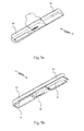
- FIGs. 5a and 5b show perspective views, respectively a top and a bottom views, of a variant implementation of the first cover 91 according to the present invention.
- said first cover 91 is made of polypropylene and comprises a rear wall 93 resting on the rear portion 62B of the frame 62 and/or on the inspection hatch 69 when the first cover 91 is mounted on the dispenser 7.
- said rear wall 93 is an integral part of the first cover 91 and is therefore made of polypropylene as well, thus protecting the other components of the door 6 from the chemical agents contained in the washing agents.
- the provision of the rear wall 93 also gives the door 6 a more pleasant aesthetic appearance in that, for example, it covers any fastening means used for securing the rear portion 62B to the front portion 62A of the frame 62 and/or any means, such as screws, used for securing the inspection hatch 69 to the hopper compartment 66.
- Said first cover 91 also comprises at least one rib 94 adapted to separate said compartments 71A, 71B, 71C, 71D from one another and to prevent the washing agents contained therein from mixing together when they are poured in.
- Fig. 5b shows that the lower portion of said first cover 91 comprises at least one small wavebreaker wall 95 adapted to fit into said compartments 71A, 71B, 71C, 71D to prevent a washing agent, in particular a liquid one, from overflowing, especially when said door 6 is closed too quickly and/or abruptly.
- a washing agent in particular a liquid one
- the second cover 92 comprises a small wavebreaker wall 95 too, as shown in particular in Figs. 3 and 4 .
- the means for connecting the washing agent dispenser 7 hydraulically to the wash tub 3 may be such as to provide a hydraulic connection between the dispenser 7 and the connection duct 73 only when the door 6 is closed.
- the hydraulic connection means differ from those shown in Fig. 2 in that the joint 72 is replaced by a valve adapted to intercept a flow section obtained on the rear portion 62B, said flow section being connected to the hopper compartment 66 and being positioned in a manner such that the flow it carries is directed towards the connection duct 73.
- This on-off valve allows the washing agents and/or the wash liquid to be sealingly confined within the door 6 when the latter is open, and to be released only after the door 6 has been properly closed.
- the on-off valve is connected, e.g. mechanically, to a drive element applied to the front part 21 of the cabinet 2, which causes the valve to open automatically when the door 6 is closed.
- the valve is equipped with a device, such as a spring or an electromechanic actuator, suitable for keeping the valve closed when the door 6 is open.
- the washing agent dispenser 7 is so designed as to have a substantially cylindrical shape, in particular the axis of said cylinder being substantially horizontal to allow the dispenser 7 to be positioned in the frame 62 above said porthole glass 61.
- the washing agent dispenser 7 having a substantially cylindrical shape allows the user to see the quantity of washing agent poured in the dispenser 7 more easily, thus facilitating a correct dosage thereof.
- said substantially cylindrical dispenser 7 comprises at least one upper aperture and a shelf adjacent thereto; preferably, said shelf is made as one piece with another component of the dispenser 7 (e.g. with the upper drawer 74) and/or is substantially parallel to the floor or slightly inclined upwards, and can support a measure cup or a container of washing agent so that the latter can be poured more easily into the dispenser 7 through said upper aperture; it can also accommodate labels and/or icons to facilitate the identification of each compartment of said plurality of compartments 71A, 71B, 71C, 71D.
- the width of the upper aperture is at least 65 mm, while the width of the shelf is at least 10 mm.
- the distance between the upper aperture and the upper edge of the door 6 is at least 85 mm.
- the substantially cylindrical dispenser 7 has at least a lower aperture for feeding the washing agents into the wash tub 3, and may comprise at least one draft adapted to facilitate the loading of the washing agents into said dispenser 7.
- the substantially cylindrical dispenser 7 may be fixed or, advantageously, it may be so designed as to either:
- the dispenser 7 By designing the dispenser 7 in a manner such that it includes at least one small rotary door or that it can rotate about its own axis, it is possible to provide a dispenser 7 which is suitable for preventing the washing agents from flowing directly into the wash tub 3 after having been poured into the dispenser 7.
- references such as notches or the like, adapted to inform the user about the required quantities of washing agents, are preferably associated with the compartments 71A, 71B, 71C, 71D.
- these embodiments of the dispenser 7 according to the present invention allow said washing agents to be fed into the wash tub 3 only after the door 6 has been closed.
- the cylindrical dispenser 7 comprising a small rotary door
- the latter switches automatically from the first to the second operating position and vice versa when the door 6 is closed and/or opened; in the case of the cylindrical dispenser 7 adapted to rotate about its own axis, the aperture of the dispenser 7 is automatically directed substantially downwards when the door 6 is closed, so as to obtain the release of the washing agents into the wash tub 3, whereas the aperture of the dispenser 7 is automatically directed substantially upwards when the door 6 is opened, so as to allow the washing agents to be poured into the dispenser 7.
- the washing agent dispenser 7 is substantially wedge-shaped, with the vertex of said wedge facing downwards, said dispenser 7 comprising an upper aperture for loading the washing agents into the dispenser 7 and a lower aperture for feeding the washing agents into the wash tub 3.
- the dispenser 7 preferably comprises:
- the substantially wedge-shaped dispenser 7 may be fixed or, advantageously, it may be so designed as to either:
- the dispenser 7 By designing the dispenser 7 in a manner such that it is substantially wedge-shaped, it is possible to provide a washing machine 1 which facilitates the loading of washing agents into said dispenser 7 without having to subject the washing machine 1 and/or components thereof, such as the door 6, to significant modifications.
- substantially wedge-shaped dispenser 7 can:
Landscapes
- Engineering & Computer Science (AREA)
- Textile Engineering (AREA)
- Detail Structures Of Washing Machines And Dryers (AREA)
- Main Body Construction Of Washing Machines And Laundry Dryers (AREA)
- Accessory Of Washing/Drying Machine, Commercial Washing/Drying Machine, Other Washing/Drying Machine (AREA)
Description
- The present invention relates to a front-loading household washing machine, in particular a laundry washing or washing/drying machine, according to the preamble of
claim 1. - The invention is applicable to the field of front-loading household washing machines, in particular laundry washing or washing/drying machines, wherein the dispenser of washing agents (detergent, softener, bleach, etc.) is located in the door that closes the load opening of the machine.
- In front-loading household washing machines known in the art, a door is used for closing the load opening through which the laundry to be washed is placed into a drum rotating inside a wash tub. The door usually includes a transparent porthole glass, which allows the user to see the internal portion of the rotary drum and the laundry loaded therein.
-
Patent GB2029862 - In
GB2260770 - Document
WO 2004/055253 A1 relates to a washing machine door comprising a container for the washing products. The upper central part of the glass (6) of the loading door (4) comprises a built-in removable container (7) for the washing products. Moreover, at least one water conduit (8), which is used to convey water the washing products, accesses the aforementioned container (7) through the hinged portion of the door (4) and is guided through the frame (5) of same. - In the washing agent dispensers known from patents
GB2029862 GB2260770 - Besides posing the risk of considerable percolation or dripping, a further problem suffered by the washing machines known from the above-mentioned documents is that the washing agent dispenser built in the porthole glass may cause a leak of washing agents onto the floor in front of the washing machine, especially when the user pours into the dispenser a quantity of washing agents in excess of the maximum allowable or recommended level. This drawback is particularly critical when liquid detergents or additives are used.
- It is also apparent that the washing agent dispenser built in the porthole glass does not allow the user to adequately see the internal portion of the rotary drum and the laundry loaded therein.
- Moreover, the washing machines described in the above-mentioned documents oblige the user to take a rather uncomfortable position in order to pour the washing agents into the appropriate dispenser, since the latter is located in a relatively low position.
- In this frame, it is the main object of the present invention to overcome the above-mentioned drawbacks by providing a front-loading household washing machine, in particular a laundry washing or washing/drying machine, so conceived as to eliminate or significantly reduce both the percolation and dripping of water from the door when the latter is opened and the leakage of washing agents, in particular when the user pours into the dispenser a quantity of washing agents in excess of the maximum allowable or recommended level.
- It is another object of the present invention to provide a front-loading household washing machine, in particular a laundry washing or washing/drying machine, which allows the user to adequately see the internal portion of the rotary drum and the laundry loaded therein.
- It is yet another object of the present invention to provide a front-loading household washing machine, in particular a laundry washing or washing/drying machine, which allows the user to pour the washing agents comfortably into the appropriate dispenser. In order to achieve these objects, the present invention provides a front-loading household washing machine, in particular a laundry washing or washing/drying machine, incorporating the features set out in the annexed claims, which are intended as an integral part of the present description.
- Further objects, features and advantages of the present invention will become apparent from the following detailed description and from the annexed drawings, which are supplied by way of non-limiting example, wherein:
-
Fig. 1 is a sectional view of a front-loading household washing machine, in particular a laundry washing or washing/drying machine, according to the present invention; -
Fig. 2 shows a door of a washing machine according to the present invention; -
Fig. 3 is an exploded view of a first possible embodiment of a washing machine door according to the present invention; -
Fig. 4 is an exploded view of a second possible embodiment of a washing machine door according to the present invention; -
Figs. 5a and 5b are perspective views, respectively from the top and from the bottom, of a variant implementation of an element of the washing machine door according to the present invention. - For clarity, in the present description the same reference numerals will be used for designating identical or equivalent items shown in the annexed drawings.
-
Fig. 1 is a sectional view of a front-loadinghousehold washing machine 1, in particular a laundry washing or washing/drying machine, according to the present invention. Thewashing machine 1 comprises a cabinet 2 within which awash tub 3 is arranged in a known manner. Inside the latter, a drum 4 is rotated about a horizontal or substantially horizontal axis X. - The laundry to be washed is placed inside the drum 4 through a load opening 5 associated with a
front part 21 of the cabinet 2. - As can be seen in particular in
Fig. 1 , the axis X of the drum 4 is preferably slightly inclined, in that it is raised towards thefront part 21 of the cabinet; this allows a user to load the laundry into the drum 4 more easily. - The
load opening 5 is closed by adoor 6 that comprises aporthole glass 61 made of transparent material and aframe 62 for supporting said porthole glass, saidporthole glass 61 preferably protruding in the direction of the axis of the drum 4 with respect to theframe 62. - When the
door 6 is closed, theporthole glass 61 is inserted into the load opening 5 and enters partially into thetub 3 and, possibly, into the drum 4; theframe 62 abuts on thefront part 21 of the cabinet 2, adjacent to the load opening 5 of said cabinet 2. According to the present invention, saiddoor 6 comprises awashing agent dispenser 7 arranged in theframe 62 above saidporthole glass 61. - The special arrangement of the
washing agent dispenser 7 according to the present invention allows to make awashing machine 1 which allows the user to: - adequately see the inner portion of the drum 4 and the laundry loaded therein, since the
porthole glass 61 does not house thewashing agent dispenser 7; - comfortably load the washing agents into the
appropriate dispenser 7, which is located at an adequate height. - The
washing machine 1 also comprises ahydraulic system 8 adapted to carry water from the household water main to adistributor 81 arranged in an upper portion 22 of the cabinet 2 and adapted to precipitate the water into a plurality ofcompartments Figs. 2 to 4 ) for feeding the washing agents (e.g. softener, detergent, etc.) contained into thedispenser 7. - In particular, said plurality of compartments includes:
- a
first compartment 71A adapted to contain a detergent for a wash phase; - a
second compartment 71B adapted to contain a softener; - a
third compartment 71C adapted to contain a bleach; - a
fourth compartment 71D adapted to contain a detergent for a prewash phase. - Each of said
compartments third compartment 71C is a removable compartment that can be inserted by a user into thefourth compartment 71D when he/she wants to use bleach for a subsequent treatment of thewashing machine 1, or extracted when he/she wants to use a prewash detergent. Preferably, saidfirst compartment 71A may be designed in a manner such as to accommodate a removable bulkhead (not shown in the drawings), in particular of the non-hermetic type. For example, it is possible to use a vertical bulkhead in which apertures have been obtained for defining a restricted overall outflow section, thus slowing down the detergent flow from thefirst compartment 71A to thewash tub 3, in particular when said detergent is a liquid one. - Referring now to
Fig. 2 , it can be noticed therein that the rotation of thedoor 6 relative to the cabinet 2 is ensured, in a known manner, by at least onehinge 63 that constrains thedoor 6 to the cabinet 2. Also, in order to keep thedoor 6 closed when thewashing machine 1 is in operation, thedoor 6 is fitted, in a known manner, with acatch 64 adapted to be coupled to a corresponding hook (not shown in the drawings) fitted to the cabinet 2. - The
door 6 of thewashing machine 1 according to the present invention comprises means for connecting thewashing agent dispenser 7 hydraulically to thetub 3, said connection means being hydraulically connected to an inlet hole (not shown in the drawings) obtained in thewash tub 3 through aconnection duct 73, preferably made of elastic material, e.g. rubber. - In particular, said hydraulic connection means may comprise a
joint 72 that provides a continuous connection between thedispenser 7 and theconnection duct 73 both when thedoor 6 is closed and when thedoor 6 is open. - The particular arrangement of the
washing agent dispenser 7 and the provision of thejoint 72 allow thewashing machine 1 to be so designed as to eliminate any risk of washing agent leakage, even should any residual water drops, possibly with a washing agent dissolved in them, remain in thedispenser 7 at the end of a wash, or should the user pour an excessive quantity of washing agents into thedispenser 7; in fact, the coupling between thejoint 72 and thedispenser 7 arranged in theframe 62 above theporthole glass 61 allows all the washing agent placed in thedispenser 7 to enter directly into thewash tub 3, in particular when thedoor 6 is opened. This prevents water percolation, possibly with a dissolved washing agent, onto the floor in front of the washing machine, unlike what happens with known washing machines, especially at the end of a wash cycle. - Furthermore, the
joint 72 may be coupled to thedoor 6 in a manner such that its axis of rotation does not coincide with the axis of rotation of saiddoor 6. In particular, thejoint 72 may be coupled to thedoor 6 in a manner such as to make a complex movement relative to the cabinet 2, said movement consisting of a combination of the rotation of thedoor 6 about the axis of said at least onehinge 63 and the rotation of thejoint 72 about its own axis. Said complex movement of thejoint 72 allows to obtain a greater opening angle of saiddoor 6, said opening angle being in particular approximately 135°. - When using a
joint 72 with an axis of rotation coinciding with the axis of rotation of thedoor 6, in particular with the axis of said at least onehinge 63, the smaller maximum opening angle of thedoor 6 is counterbalanced by the possibility of using afixed joint 72. -
Figs. 3 and4 are exploded views of a first and a second possible embodiments of thedoor 6 of thewashing machine 1 according to the present invention. - Such drawings clearly show that the
frame 62 of thedoor 6 comprises afront portion 62A and arear portion 62B, theporthole glass 61 fitting into apassage 62C obtained in therear portion 62B and being coupled to saidrear portion 62B through anelement 65, in particular the latter having substantially a truncated-cone shape. - The
porthole glass 61 is secured by glueing or welding (in particular by vibration welding) or by means of screw or joint connections between theelement 65 and therear portion 62B with theporthole glass 61 sandwiched in between, so as to form an assembly as per the process specified in patent application for inventionWO2007/000645 in the name of the present Applicant, the teachings of which are intended as an integral part of the present description. - The
door 6 also comprises ahopper compartment 66 adapted to house thedispenser 7 and to convey the washing agents into acoupling 67 connected to thejoint 72, preferably by interposing at least afirst sealing element 67A between thecoupling 67 and thejoint 72. - The assembly consisting of the
porthole glass 61, the truncated-cone element 65 and therear portion 62B is then connected, by glueing or welding (in particular by vibration welding) or by means of screw or joint connections, to thefront portion 62A, with thehopper compartment 66 in between. As a consequence, in this condition thehopper compartment 66 stays locked between thefront portion 62A and the assembly consisting of theporthole glass 61, the truncated-cone element 65 and therear portion 62B, while still being in a position that provides easy access for cleaning (after removing the drawer above). - In particular, in the first embodiment shown in
Fig. 3 it can be noted that: - the
coupling 67 is made as one piece with thehopper compartment 66; - the
hopper compartment 66 is made separately from the truncated-cone element 65; - the
dispenser 7, thehopper compartment 66, thecoupling 67 and the joint 72 come directly in contact with the detergent and are made of a plastic material resistant to the chemical agents included in the detergent, preferably PP (polypropylene); - the
porthole glass 61 and thefront portion 62A are made of a substantially transparent material, preferably theporthole glass 61 being made of glass and thefront portion 62A being made of a plastic material such as, for example, SAN (styrene acrylonitrile copolymer) or mass metallized ABS (acrylonitrile-butadiene-styrene) or PC (polycarbonate); - the
rear portion 62B and the truncated-cone portion 65 are made of a different plastic material, preferably ABS (acrylonitrile-butadiene-styrene). - The second embodiment shown in
Fig. 4 is very similar to the first embodiment ofFig. 3 , the main differences being that in the second embodiment ofFig. 4 : - the
coupling 67 is manufactured separately from thehopper compartment 66. With this design, it is appropriate to insert asecond sealing element 67B to prevent any leakage of wash liquid between thehopper compartment 66 and thecoupling 67; - the
hopper compartment 66 is made as one piece with the truncated-cone element 65 by means of a single moulding operation. The truncated-cone element 65 and thehopper compartment 66 are both made of ABS (acrylonitrile-butadiene-styrene), i.e. a plastic material which preferably must not regularly come in contact with chemical agents contained in detergents. - Consequently, in the second embodiment of
Fig. 4 thedispenser 7 comprises anupper drawer 74 and alower drawer 75 connected to each other so as to form one piece, in particular by glueing or welding, preferably by vibration welding. Preferably, saidlower drawer 75 is made of a plastic material resistant to the chemical agents contained in the detergent, in particular PP (polypropylene). Thanks to its particular design, thelower drawer 75 has the function of conveying the washing agents from thecompartments coupling 67 without the chemical agents contained in the detergents coming in contact with and damaging thehopper compartment 66. - It is however apparent that in the practical implementation the details shown in
Figs. 3 and4 may have different shapes and be replaced with other technically equivalent elements. - In
Figs. 3 and4 it is also possible to see that thedispenser 7 may comprise one or more of the following elements: - a
first cover 91 adapted to be associated with the plurality ofcompartments - a siphon 76 for at least one of said plurality of
compartments second compartment 71B intended for a softener; - a
second cover 92 adapted to be associated with at least one compartment of said plurality ofcompartments third compartment 71C intended for a bleach. -
Figs. 3 and4 also show that thedoor 6 comprises a printedcircuit board 68 for controlling the operation of thewashing machine 1 according to the present invention, said printedcircuit board 68 being associated with acontrol box 68A and akeyboard 68B. - The
door 6 also comprises aninspection hatch 69 that provides access to the printedcircuit board 68. Preferably, saidinspection hatch 69 is fitted with sealing means, in particular a co-moulded gasket (not shown in the drawings), which allow the printedcircuit board 68 to be kept isolated from water and wash liquid. - The advantages offered by a front-loading household washing machine, in particular a laundry washing or washing/drying machine, according to the present invention are apparent from the above description.
- In particular, such advantages lie in that the arrangement of the
washing agent dispenser 7 in theframe 62 above saidporthole glass 61 allows to reduce the percolation or dripping of water from thedoor 6 when the latter is opened. Thedispenser 7 and the joint 72 allow thewashing machine 1 to be so designed as to prevent any leakage of washing agents, in particular when some residual wash liquid remains in thedispenser 7 at the end of the wash; in fact, the coupling between the joint 72 and thedispenser 7 arranged in theframe 62 above theporthole glass 61 allows all the washing agent placed in thedispenser 7 to enter directly into thetub 3 also after opening thedoor 6. This prevents water percolation, possibly with a dissolved washing agent, onto the floor in front of the washing machine, unlike what happens with known washing machines, especially at the end of a wash cycle. - Thus, the
dispenser 7 and the joint 72 allow thewashing machine 1 to be designed in a manner such as to prevent any leakage of washing agents, even when the user pours a quantity of washing agents into thedispenser 7 in excess of the maximum allowable or recommended level, since said washing agents are in any case fed into thewash tub 3. - Furthermore, the special arrangement of the
dispenser 7 in accordance with the present invention allows to provide awashing machine 1 that allows the user to adequately see the inner portion of thewash tub 3 and the laundry loaded in the drum 4, as well as to comfortably pour the washing agents into theappropriate dispenser 7. - Another advantage of the washing machine according to the present invention is that a single operation, i.e. opening the
door 6, is required to gain access both to thedispenser 7 for pouring in the washing agents and to theload opening 5 for loading the textile items to be treated. What is more, the machine according to the present invention is characterized by including components, such as thecompartments hopper compartment 66 and the nozzles of thedistributor 81, which are easily accessible for cleaning. - The front-loading household washing machine described herein by way of example may be subject to many possible variations without departing from the novelty spirit of the inventive idea; it is also clear that in the practical implementation of the invention the illustrated details may have different shapes or be replaced with other technically equivalent elements.
- For example,
Figs. 5a and 5b show perspective views, respectively a top and a bottom views, of a variant implementation of thefirst cover 91 according to the present invention. - In
Fig. 5a , saidfirst cover 91 is made of polypropylene and comprises arear wall 93 resting on therear portion 62B of theframe 62 and/or on theinspection hatch 69 when thefirst cover 91 is mounted on thedispenser 7. Preferably, saidrear wall 93 is an integral part of thefirst cover 91 and is therefore made of polypropylene as well, thus protecting the other components of thedoor 6 from the chemical agents contained in the washing agents. The provision of therear wall 93 also gives the door 6 a more pleasant aesthetic appearance in that, for example, it covers any fastening means used for securing therear portion 62B to thefront portion 62A of theframe 62 and/or any means, such as screws, used for securing theinspection hatch 69 to thehopper compartment 66. - Said
first cover 91 also comprises at least onerib 94 adapted to separate saidcompartments - In addition,
Fig. 5b shows that the lower portion of saidfirst cover 91 comprises at least onesmall wavebreaker wall 95 adapted to fit into saidcompartments door 6 is closed too quickly and/or abruptly. - Preferably, the
second cover 92 comprises asmall wavebreaker wall 95 too, as shown in particular inFigs. 3 and4 . - In another variant embodiment of the
washing machine 1 according to the present invention, the means for connecting thewashing agent dispenser 7 hydraulically to thewash tub 3 may be such as to provide a hydraulic connection between thedispenser 7 and theconnection duct 73 only when thedoor 6 is closed. In this case, the hydraulic connection means differ from those shown inFig. 2 in that the joint 72 is replaced by a valve adapted to intercept a flow section obtained on therear portion 62B, said flow section being connected to thehopper compartment 66 and being positioned in a manner such that the flow it carries is directed towards theconnection duct 73. This on-off valve allows the washing agents and/or the wash liquid to be sealingly confined within thedoor 6 when the latter is open, and to be released only after thedoor 6 has been properly closed. To this end, the on-off valve is connected, e.g. mechanically, to a drive element applied to thefront part 21 of the cabinet 2, which causes the valve to open automatically when thedoor 6 is closed. Furthermore, the valve is equipped with a device, such as a spring or an electromechanic actuator, suitable for keeping the valve closed when thedoor 6 is open. - In another variant implementation (not shown in the drawings) of the
washing machine 1 according to the present invention, thewashing agent dispenser 7 is so designed as to have a substantially cylindrical shape, in particular the axis of said cylinder being substantially horizontal to allow thedispenser 7 to be positioned in theframe 62 above saidporthole glass 61. - The
washing agent dispenser 7 having a substantially cylindrical shape allows the user to see the quantity of washing agent poured in thedispenser 7 more easily, thus facilitating a correct dosage thereof. - Preferably, said substantially
cylindrical dispenser 7 comprises at least one upper aperture and a shelf adjacent thereto; preferably, said shelf is made as one piece with another component of the dispenser 7 (e.g. with the upper drawer 74) and/or is substantially parallel to the floor or slightly inclined upwards, and can support a measure cup or a container of washing agent so that the latter can be poured more easily into thedispenser 7 through said upper aperture; it can also accommodate labels and/or icons to facilitate the identification of each compartment of said plurality ofcompartments door 6 is at least 85 mm. Furthermore, the substantiallycylindrical dispenser 7 has at least a lower aperture for feeding the washing agents into thewash tub 3, and may comprise at least one draft adapted to facilitate the loading of the washing agents into saiddispenser 7. - The substantially
cylindrical dispenser 7 may be fixed or, advantageously, it may be so designed as to either: - include at least one small rotary door adapted to switch from a first operating position, wherein an upper aperture for feeding the washing agents into the
dispenser 7 is open and a lower aperture for feeding the washing agents into thewash tub 3 is closed, to a second operating position, wherein the upper aperture is closed and the lower aperture is open, so as to allow the washing agents to be fed into thewash tub 3. Preferably, said first operating position is set automatically when thedoor 6 of thewashing machine 1 is opened, whereas said second operating position is set automatically when saiddoor 6 is closed;
or - rotate about its own axis in order to switch from a first washing agent loading position, wherein an aperture of the
dispenser 7 is directed substantially upwards, to a second washing agent release position for feeding the washing agents into thewash tub 3, wherein the aperture of thedispenser 7 is directed substantially downwards. Preferably, said first loading position is set automatically when thedoor 6 is opened, whereas said second release position is set automatically when saiddoor 6 is closed. - By designing the
dispenser 7 in a manner such that it includes at least one small rotary door or that it can rotate about its own axis, it is possible to provide adispenser 7 which is suitable for preventing the washing agents from flowing directly into thewash tub 3 after having been poured into thedispenser 7. In this case, references such as notches or the like, adapted to inform the user about the required quantities of washing agents, are preferably associated with thecompartments dispenser 7 according to the present invention allow said washing agents to be fed into thewash tub 3 only after thedoor 6 has been closed. In particular, in the case of thecylindrical dispenser 7 comprising a small rotary door, the latter switches automatically from the first to the second operating position and vice versa when thedoor 6 is closed and/or opened; in the case of thecylindrical dispenser 7 adapted to rotate about its own axis, the aperture of thedispenser 7 is automatically directed substantially downwards when thedoor 6 is closed, so as to obtain the release of the washing agents into thewash tub 3, whereas the aperture of thedispenser 7 is automatically directed substantially upwards when thedoor 6 is opened, so as to allow the washing agents to be poured into thedispenser 7. - In a further variant embodiment (not shown in the drawings) of the
washing machine 1 according to the present invention, thewashing agent dispenser 7 is substantially wedge-shaped, with the vertex of said wedge facing downwards, saiddispenser 7 comprising an upper aperture for loading the washing agents into thedispenser 7 and a lower aperture for feeding the washing agents into thewash tub 3. - The particular shape of the
dispenser 7 allows the user to see the quantity of washing agent poured in thedispenser 7 more easily, thus facilitating a correct dosage thereof. In this case as well, the dispenser preferably comprises: - a shelf adjacent to the upper aperture of the
dispenser 7, made as one piece with another component of the dispenser 7 (e.g. with the upper drawer 74) and/or substantially parallel to the floor or slightly inclined upwards. The shelf can support a measure cup or a container of washing agent, so that the latter can be poured more easily into thedispenser 7 through said upper aperture; it can also accommodate labels and/or icons to facilitate the identification of each compartment of said plurality ofcompartments door 6 is at least 85 mm; - at least one draft to facilitate the loading of the washing agents into said
dispenser 7. - The substantially wedge-shaped
dispenser 7 may be fixed or, advantageously, it may be so designed as to either: - pivot about said downward-facing vertex in order to switch from a first operating position, wherein the
dispenser 7 is substantially housed in theframe 62 above saidporthole glass 61 and said upper aperture is minimally open, to a second operating position, wherein thedispenser 7 is substantially extracted from theframe 62 and said upper aperture is fully open. Preferably, said first operating position is set automatically when thedoor 6 of thewashing machine 1 is closed, whereas said second operating position is set automatically when saiddoor 6 is opened. The pivoting action determines, for example, a forward movement of the front portion of thedispenser 7 by approximately 30 mm;
or - comprise side walls made of a deformable material, in particular an elastomeric material (rubber and/or silicone), so as to obtain a "bellows-like" opening and/or closing of the
dispenser 7 relative to theframe 62. In this case as well, thedispenser 7 can thus switch from a first operating position, wherein the upper aperture is fully open, to a second operating position, wherein the upper aperture is minimally open. Preferably, said first operating position is set automatically when thedoor 6 of thewashing machine 1 is opened, whereas said second operating position is set automatically when saiddoor 6 is closed. - By designing the
dispenser 7 in a manner such that it is substantially wedge-shaped, it is possible to provide awashing machine 1 which facilitates the loading of washing agents into saiddispenser 7 without having to subject thewashing machine 1 and/or components thereof, such as thedoor 6, to significant modifications. - In addition, the fact that the substantially wedge-shaped
dispenser 7 can: - pivot, or
- comprise side walls made of a deformable material, so as to obtain a "bellows-like" opening and/or closing action,
- It can therefore be easily understood that the present invention is not limited to the above-described front-loading household washing machine, in particular a laundry washing or washing/drying machine, but may be subject to many modifications, improvements or replacements of equivalent parts and elements without departing from the inventive idea, as clearly specified in the following claims.
Claims (16)
- Front-loading household washing machine (1), in particular a laundry washing or washing/drying machine, comprising a cabinet (2) within which a wash tub (3) is arranged, and having a load opening (5) that can be closed by a door (6) constrained to said cabinet (2), said door (6) comprising a porthole glass (61) adapted to fit at least partly into said load opening (5) and a frame (62) supporting said porthole glass (61),
characterized in that
said door (6) comprises a washing agent dispenser (7) arranged in the frame (62) above said porthole glass (61). - Washing machine (1) according to claim 1, characterized in that said door (6) comprises means for connecting the washing agent dispenser (7) hydraulically to said wash tub (3), said connection means being hydraulically connected to an inlet hole obtained in the wash tub (3) through a connection duct (73) preferably made of elastic material.
- Washing machine (1) according to claim 2, characterized in that said hydraulic connection means comprise a joint (72) that provides a continuous connection between the dispenser (7) and the connection duct (73) both when the door (6) is closed and when the door (6) is open.
- Washing machine (1) according to claim 2, characterized in that said hydraulic connection means comprise a valve adapted to provide the hydraulic connection between the dispenser (7) and the wash tub (3) when said door (6) is closed and to break the hydraulic connection between the dispenser (7) and the wash tub (3) when said door (6) is open.
- Washing machine (1) according to claim 1, characterized in that said frame (62) of the door (6) comprises a front portion (62A) and a rear portion (62B), said porthole glass (61) fitting into a passage (62C) obtained in the rear portion (62B) and being coupled to said rear portion (62B) through an element (65), in particular the latter having substantially a truncated-cone shape.
- Washing machine (1) according to claim 1, characterized by comprising a printed circuit board (68) for controlling the operation of said washing machine (1), said printed circuit board (68) being preferably associated with a control box (68A) and a keyboard (68B), said door (6) comprising an inspection hatch (69) that provides access to the printed circuit board (68).
- Washing machine (1) according to claim 1, characterized by comprising a hydraulic system (8) adapted to carry water from the household water main to a distributor (81) arranged in an upper portion (22) of the cabinet (2) and to precipitate the water into a plurality of compartments (71A, 71B, 71C, 71D) for feeding the washing agents contained in the dispenser (7).
- Washing machine (1) according to claim 7, characterized in that said dispenser (7) comprises a first cover (91) adapted to be associated with said plurality of compartments (71A, 71B, 71C, 71D).
- Washing machine (1) according to claim 7, characterized in that said dispenser (7) comprises a second cover (92) adapted to be associated with at least one compartment of said plurality of compartments (71A, 71B, 71C, 71D), in particular said at least one compartment being a third compartment (71C) intended for bleach.
- Washing machine (1) according to claim 1, characterized in that said washing agent dispenser (7) has a substantially cylindrical shape, in particular the axis of said cylinder being substantially horizontal in order to allow the dispenser (7) to be positioned in the frame (62) above said porthole glass (61).
- Washing machine (1) according to claim 10, characterized in that said dispenser (7) having a substantially cylindrical shape is so designed as to include at least one lower aperture for feeding the washing agents into the wash tub (3).
- Washing machine (1) according to claim 10, characterized in that said dispenser (7) having a substantially cylindrical shape is so designed as to include at least one small rotary door adapted to switch from a first operating position, wherein an upper aperture for feeding the washing agents into the dispenser (7) is open and a lower aperture for feeding the washing agents into the wash tub (3) is closed, to a second operating position, wherein the upper aperture is closed and the lower aperture is open.
- Washing machine (1) according to claim 10, characterized in that said dispenser (7) having a substantially cylindrical shape is so designed as to rotate about its own axis in order to switch from a first washing agent loading position, wherein an aperture of the dispenser (7) is directed substantially upwards, to a second washing agent release position for feeding the washing agents into the wash tub (3), wherein the aperture of the dispenser (7) is directed substantially downwards.
- Washing machine (1) according to claim 1, characterized in that said washing agent dispenser (7) is substantially wedge-shaped, with the vertex of said wedge facing downwards, said dispenser (7) comprising an upper aperture for loading the washing agents into the dispenser (7) and a lower aperture for feeding the washing agents into the wash tub (3).
- Washing machine (1) according to claim 14, characterized in that said substantially wedge-shaped dispenser (7) is so designed as to pivot about said downward-facing vertex in order to switch from a first operating position, wherein the dispenser (7) is substantially housed in the frame (62) above said porthole glass (61) and said upper aperture is minimally open, to a second operating position, wherein the dispenser (7) is substantially extracted from the frame (62) and said upper aperture is fully open.
- Washing machine (1) according to claim 14, characterized in that said substantially wedge-shaped dispenser (7) is so designed as to provide a "bellows-like" opening and/or closing of the dispenser (7) relative to the frame (62) in order to switch from a first operating condition, wherein the upper aperture is fully open, to a second operating position, wherein the upper aperture is minimally open.
Priority Applications (1)
| Application Number | Priority Date | Filing Date | Title |
|---|---|---|---|
| PL10723783T PL2425047T3 (en) | 2009-04-30 | 2010-04-29 | Front-loading household washing machine, in particular a laundry washing or washing/drying machine |
Applications Claiming Priority (2)
| Application Number | Priority Date | Filing Date | Title |
|---|---|---|---|
| ITTO2009A000345A IT1394005B1 (en) | 2009-04-30 | 2009-04-30 | WASHING MACHINE WITH FRONTAL HOUSEHOLD USE, IN PARTICULAR WASHING MACHINE OR WASHING MACHINE |
| PCT/IB2010/051889 WO2010125538A1 (en) | 2009-04-30 | 2010-04-29 | Front-loading household washing machine, in particular a laundry washing or washing/drying machine |
Publications (2)
| Publication Number | Publication Date |
|---|---|
| EP2425047A1 EP2425047A1 (en) | 2012-03-07 |
| EP2425047B1 true EP2425047B1 (en) | 2015-01-28 |
Family
ID=42110065
Family Applications (1)
| Application Number | Title | Priority Date | Filing Date |
|---|---|---|---|
| EP10723783.6A Not-in-force EP2425047B1 (en) | 2009-04-30 | 2010-04-29 | Front-loading household washing machine, in particular a laundry washing or washing/drying machine |
Country Status (5)
| Country | Link |
|---|---|
| EP (1) | EP2425047B1 (en) |
| ES (1) | ES2533529T3 (en) |
| IT (1) | IT1394005B1 (en) |
| PL (1) | PL2425047T3 (en) |
| WO (1) | WO2010125538A1 (en) |
Families Citing this family (7)
| Publication number | Priority date | Publication date | Assignee | Title |
|---|---|---|---|---|
| ITTO20100862A1 (en) * | 2010-10-27 | 2012-04-28 | Indesit Co Spa | WASHING MACHINE WITH FRONTAL HOUSEHOLD USE, IN PARTICULAR WASHING MACHINE OR WASHING MACHINE. |
| US9388523B2 (en) * | 2011-08-31 | 2016-07-12 | Lg Electronics Inc. | Laundry treating apparatus |
| US9469931B2 (en) | 2011-12-21 | 2016-10-18 | Whirlpool Corporation | Laundry treating appliance door with planar window element and baffle for controlling laundry movement |
| US9115461B2 (en) | 2011-12-21 | 2015-08-25 | Whirlpool Corporation | Door wash aid dispenser for a laundry treating appliance |
| EP2896737B1 (en) * | 2014-01-15 | 2017-03-22 | Electrolux Appliances Aktiebolag | Fluid supply for a household appliance and household appliance |
| EP3502335B1 (en) * | 2017-12-22 | 2022-02-09 | Candy S.p.A. | Washing machine |
| ES2881900T3 (en) * | 2018-09-17 | 2021-11-30 | Candy Spa | Door-hinge assembly on a washing machine |
Family Cites Families (3)
| Publication number | Priority date | Publication date | Assignee | Title |
|---|---|---|---|---|
| IT1256272B (en) * | 1991-10-22 | 1995-11-29 | Zanussi Elettrodomestici | WASHING MACHINE WITH DETERGENT CONTAINER RECOVERED IN THE PORTHOLE |
| ES2226550B1 (en) * | 2002-12-18 | 2006-06-01 | Incaelec, S.L. | LOADING DOOR OF WASHER CARRIER OF THE RECEIVING BUCKET OF WASHING PRODUCTS. |
| KR20060023016A (en) * | 2004-09-08 | 2006-03-13 | 엘지전자 주식회사 | washer |
-
2009
- 2009-04-30 IT ITTO2009A000345A patent/IT1394005B1/en active
-
2010
- 2010-04-29 ES ES10723783.6T patent/ES2533529T3/en active Active
- 2010-04-29 EP EP10723783.6A patent/EP2425047B1/en not_active Not-in-force
- 2010-04-29 WO PCT/IB2010/051889 patent/WO2010125538A1/en not_active Ceased
- 2010-04-29 PL PL10723783T patent/PL2425047T3/en unknown
Also Published As
| Publication number | Publication date |
|---|---|
| ES2533529T3 (en) | 2015-04-10 |
| ITTO20090345A1 (en) | 2010-11-01 |
| EP2425047A1 (en) | 2012-03-07 |
| PL2425047T3 (en) | 2015-06-30 |
| WO2010125538A1 (en) | 2010-11-04 |
| IT1394005B1 (en) | 2012-05-17 |
Similar Documents
| Publication | Publication Date | Title |
|---|---|---|
| EP2425047A1 (en) | Front-loading household washing machine, in particular a laundry washing or washing/drying machine | |
| EP2743393B1 (en) | A front-loading laundry washing machine for household use, in particular a washing or washing/drying machine | |
| KR950014449A (en) | Front-loading Washer | |
| US20070125134A1 (en) | Detergent supply apparatus of washing machine | |
| US6622896B2 (en) | Dishwasher detergent dispenser | |
| CN110291244A (en) | washing machine | |
| US8959962B2 (en) | Washer/dryer | |
| EP3293303B1 (en) | Laundry treating appliance with a slidable dispenser | |
| KR102044106B1 (en) | Dual washing machine | |
| EP1951947B1 (en) | Front-loading laundry washing machine | |
| US11708657B2 (en) | Laundry treating appliance and dispenser | |
| AU758082B2 (en) | Dishwashing machine, in particular for home use, having a functional loading door | |
| KR20170140623A (en) | Dish Washer | |
| CA2265351C (en) | Dispenser for front loading washing machine | |
| EP0731203B1 (en) | A condensation laundry dryer with arrangements for collecting condensation water in a container | |
| KR20170096321A (en) | Apparatus for injecting liquid additive in washing machine | |
| CN101346090A (en) | Dishwasher with improved structure of in-door supply device | |
| US12209351B2 (en) | Washing machine | |
| KR20140065859A (en) | Laundry treating apparatus | |
| KR101938245B1 (en) | Laundry treating apparatus | |
| KR20220112503A (en) | Washing machine | |
| EP2633115B1 (en) | A front-loading laundry washing machine for household use, in particular a washing or washing/drying machine | |
| KR20100068892A (en) | Washing machine |
Legal Events
| Date | Code | Title | Description |
|---|---|---|---|
| PUAI | Public reference made under article 153(3) epc to a published international application that has entered the european phase |
Free format text: ORIGINAL CODE: 0009012 |
|
| 17P | Request for examination filed |
Effective date: 20111104 |
|
| AK | Designated contracting states |
Kind code of ref document: A1 Designated state(s): AT BE BG CH CY CZ DE DK EE ES FI FR GB GR HR HU IE IS IT LI LT LU LV MC MK MT NL NO PL PT RO SE SI SK SM TR |
|
| DAX | Request for extension of the european patent (deleted) | ||
| GRAJ | Information related to disapproval of communication of intention to grant by the applicant or resumption of examination proceedings by the epo deleted |
Free format text: ORIGINAL CODE: EPIDOSDIGR1 |
|
| GRAP | Despatch of communication of intention to grant a patent |
Free format text: ORIGINAL CODE: EPIDOSNIGR1 |
|
| GRAP | Despatch of communication of intention to grant a patent |
Free format text: ORIGINAL CODE: EPIDOSNIGR1 |
|
| GRAS | Grant fee paid |
Free format text: ORIGINAL CODE: EPIDOSNIGR3 |
|
| INTG | Intention to grant announced |
Effective date: 20141203 |
|
| GRAA | (expected) grant |
Free format text: ORIGINAL CODE: 0009210 |
|
| AK | Designated contracting states |
Kind code of ref document: B1 Designated state(s): AT BE BG CH CY CZ DE DK EE ES FI FR GB GR HR HU IE IS IT LI LT LU LV MC MK MT NL NO PL PT RO SE SI SK SM TR |
|
| REG | Reference to a national code |
Ref country code: GB Ref legal event code: FG4D |
|
| REG | Reference to a national code |
Ref country code: CH Ref legal event code: EP |
|
| REG | Reference to a national code |
Ref country code: IE Ref legal event code: FG4D |
|
| REG | Reference to a national code |
Ref country code: DE Ref legal event code: R096 Ref document number: 602010022108 Country of ref document: DE Effective date: 20150312 |
|
| REG | Reference to a national code |
Ref country code: AT Ref legal event code: REF Ref document number: 708294 Country of ref document: AT Kind code of ref document: T Effective date: 20150315 |
|
| REG | Reference to a national code |
Ref country code: FR Ref legal event code: PLFP Year of fee payment: 6 |
|
| REG | Reference to a national code |
Ref country code: ES Ref legal event code: FG2A Ref document number: 2533529 Country of ref document: ES Kind code of ref document: T3 Effective date: 20150410 |
|
| REG | Reference to a national code |
Ref country code: AT Ref legal event code: MK05 Ref document number: 708294 Country of ref document: AT Kind code of ref document: T Effective date: 20150128 |
|
| REG | Reference to a national code |
Ref country code: NL Ref legal event code: VDEP Effective date: 20150128 |
|
| REG | Reference to a national code |
Ref country code: LT Ref legal event code: MG4D |
|
| REG | Reference to a national code |
Ref country code: PL Ref legal event code: T3 |
|
| PG25 | Lapsed in a contracting state [announced via postgrant information from national office to epo] |
Ref country code: NO Free format text: LAPSE BECAUSE OF FAILURE TO SUBMIT A TRANSLATION OF THE DESCRIPTION OR TO PAY THE FEE WITHIN THE PRESCRIBED TIME-LIMIT Effective date: 20150428 Ref country code: LT Free format text: LAPSE BECAUSE OF FAILURE TO SUBMIT A TRANSLATION OF THE DESCRIPTION OR TO PAY THE FEE WITHIN THE PRESCRIBED TIME-LIMIT Effective date: 20150128 Ref country code: FI Free format text: LAPSE BECAUSE OF FAILURE TO SUBMIT A TRANSLATION OF THE DESCRIPTION OR TO PAY THE FEE WITHIN THE PRESCRIBED TIME-LIMIT Effective date: 20150128 Ref country code: SE Free format text: LAPSE BECAUSE OF FAILURE TO SUBMIT A TRANSLATION OF THE DESCRIPTION OR TO PAY THE FEE WITHIN THE PRESCRIBED TIME-LIMIT Effective date: 20150128 Ref country code: HR Free format text: LAPSE BECAUSE OF FAILURE TO SUBMIT A TRANSLATION OF THE DESCRIPTION OR TO PAY THE FEE WITHIN THE PRESCRIBED TIME-LIMIT Effective date: 20150128 Ref country code: BG Free format text: LAPSE BECAUSE OF FAILURE TO SUBMIT A TRANSLATION OF THE DESCRIPTION OR TO PAY THE FEE WITHIN THE PRESCRIBED TIME-LIMIT Effective date: 20150428 |
|
| PG25 | Lapsed in a contracting state [announced via postgrant information from national office to epo] |
Ref country code: NL Free format text: LAPSE BECAUSE OF FAILURE TO SUBMIT A TRANSLATION OF THE DESCRIPTION OR TO PAY THE FEE WITHIN THE PRESCRIBED TIME-LIMIT Effective date: 20150128 Ref country code: IS Free format text: LAPSE BECAUSE OF FAILURE TO SUBMIT A TRANSLATION OF THE DESCRIPTION OR TO PAY THE FEE WITHIN THE PRESCRIBED TIME-LIMIT Effective date: 20150528 Ref country code: AT Free format text: LAPSE BECAUSE OF FAILURE TO SUBMIT A TRANSLATION OF THE DESCRIPTION OR TO PAY THE FEE WITHIN THE PRESCRIBED TIME-LIMIT Effective date: 20150128 Ref country code: LV Free format text: LAPSE BECAUSE OF FAILURE TO SUBMIT A TRANSLATION OF THE DESCRIPTION OR TO PAY THE FEE WITHIN THE PRESCRIBED TIME-LIMIT Effective date: 20150128 Ref country code: GR Free format text: LAPSE BECAUSE OF FAILURE TO SUBMIT A TRANSLATION OF THE DESCRIPTION OR TO PAY THE FEE WITHIN THE PRESCRIBED TIME-LIMIT Effective date: 20150429 |
|
| REG | Reference to a national code |
Ref country code: DE Ref legal event code: R097 Ref document number: 602010022108 Country of ref document: DE |
|
| PG25 | Lapsed in a contracting state [announced via postgrant information from national office to epo] |
Ref country code: EE Free format text: LAPSE BECAUSE OF FAILURE TO SUBMIT A TRANSLATION OF THE DESCRIPTION OR TO PAY THE FEE WITHIN THE PRESCRIBED TIME-LIMIT Effective date: 20150128 Ref country code: SK Free format text: LAPSE BECAUSE OF FAILURE TO SUBMIT A TRANSLATION OF THE DESCRIPTION OR TO PAY THE FEE WITHIN THE PRESCRIBED TIME-LIMIT Effective date: 20150128 Ref country code: DK Free format text: LAPSE BECAUSE OF FAILURE TO SUBMIT A TRANSLATION OF THE DESCRIPTION OR TO PAY THE FEE WITHIN THE PRESCRIBED TIME-LIMIT Effective date: 20150128 Ref country code: RO Free format text: LAPSE BECAUSE OF FAILURE TO SUBMIT A TRANSLATION OF THE DESCRIPTION OR TO PAY THE FEE WITHIN THE PRESCRIBED TIME-LIMIT Effective date: 20150128 Ref country code: CZ Free format text: LAPSE BECAUSE OF FAILURE TO SUBMIT A TRANSLATION OF THE DESCRIPTION OR TO PAY THE FEE WITHIN THE PRESCRIBED TIME-LIMIT Effective date: 20150128 |
|
| PG25 | Lapsed in a contracting state [announced via postgrant information from national office to epo] |
Ref country code: MC Free format text: LAPSE BECAUSE OF FAILURE TO SUBMIT A TRANSLATION OF THE DESCRIPTION OR TO PAY THE FEE WITHIN THE PRESCRIBED TIME-LIMIT Effective date: 20150128 Ref country code: LU Free format text: LAPSE BECAUSE OF FAILURE TO SUBMIT A TRANSLATION OF THE DESCRIPTION OR TO PAY THE FEE WITHIN THE PRESCRIBED TIME-LIMIT Effective date: 20150429 |
|
| REG | Reference to a national code |
Ref country code: CH Ref legal event code: PL |
|
| PLBE | No opposition filed within time limit |
Free format text: ORIGINAL CODE: 0009261 |
|
| STAA | Information on the status of an ep patent application or granted ep patent |
Free format text: STATUS: NO OPPOSITION FILED WITHIN TIME LIMIT |
|
| 26N | No opposition filed |
Effective date: 20151029 |
|
| REG | Reference to a national code |
Ref country code: IE Ref legal event code: MM4A |
|
| PG25 | Lapsed in a contracting state [announced via postgrant information from national office to epo] |
Ref country code: LI Free format text: LAPSE BECAUSE OF NON-PAYMENT OF DUE FEES Effective date: 20150430 Ref country code: CH Free format text: LAPSE BECAUSE OF NON-PAYMENT OF DUE FEES Effective date: 20150430 |
|
| PG25 | Lapsed in a contracting state [announced via postgrant information from national office to epo] |
Ref country code: SI Free format text: LAPSE BECAUSE OF FAILURE TO SUBMIT A TRANSLATION OF THE DESCRIPTION OR TO PAY THE FEE WITHIN THE PRESCRIBED TIME-LIMIT Effective date: 20150128 |
|
| REG | Reference to a national code |
Ref country code: FR Ref legal event code: PLFP Year of fee payment: 7 |
|
| PG25 | Lapsed in a contracting state [announced via postgrant information from national office to epo] |
Ref country code: IE Free format text: LAPSE BECAUSE OF NON-PAYMENT OF DUE FEES Effective date: 20150429 |
|
| PGFP | Annual fee paid to national office [announced via postgrant information from national office to epo] |
Ref country code: ES Payment date: 20160311 Year of fee payment: 7 |
|
| PG25 | Lapsed in a contracting state [announced via postgrant information from national office to epo] |
Ref country code: BE Free format text: LAPSE BECAUSE OF FAILURE TO SUBMIT A TRANSLATION OF THE DESCRIPTION OR TO PAY THE FEE WITHIN THE PRESCRIBED TIME-LIMIT Effective date: 20150128 |
|
| PG25 | Lapsed in a contracting state [announced via postgrant information from national office to epo] |
Ref country code: MT Free format text: LAPSE BECAUSE OF FAILURE TO SUBMIT A TRANSLATION OF THE DESCRIPTION OR TO PAY THE FEE WITHIN THE PRESCRIBED TIME-LIMIT Effective date: 20150128 |
|
| REG | Reference to a national code |
Ref country code: FR Ref legal event code: PLFP Year of fee payment: 8 |
|
| PG25 | Lapsed in a contracting state [announced via postgrant information from national office to epo] |
Ref country code: HU Free format text: LAPSE BECAUSE OF FAILURE TO SUBMIT A TRANSLATION OF THE DESCRIPTION OR TO PAY THE FEE WITHIN THE PRESCRIBED TIME-LIMIT; INVALID AB INITIO Effective date: 20100429 Ref country code: SM Free format text: LAPSE BECAUSE OF FAILURE TO SUBMIT A TRANSLATION OF THE DESCRIPTION OR TO PAY THE FEE WITHIN THE PRESCRIBED TIME-LIMIT Effective date: 20150128 |
|
| PG25 | Lapsed in a contracting state [announced via postgrant information from national office to epo] |
Ref country code: CY Free format text: LAPSE BECAUSE OF FAILURE TO SUBMIT A TRANSLATION OF THE DESCRIPTION OR TO PAY THE FEE WITHIN THE PRESCRIBED TIME-LIMIT Effective date: 20150128 |
|
| PGFP | Annual fee paid to national office [announced via postgrant information from national office to epo] |
Ref country code: TR Payment date: 20170324 Year of fee payment: 8 |
|
| PG25 | Lapsed in a contracting state [announced via postgrant information from national office to epo] |
Ref country code: PT Free format text: LAPSE BECAUSE OF FAILURE TO SUBMIT A TRANSLATION OF THE DESCRIPTION OR TO PAY THE FEE WITHIN THE PRESCRIBED TIME-LIMIT Effective date: 20150528 |
|
| REG | Reference to a national code |
Ref country code: FR Ref legal event code: PLFP Year of fee payment: 9 |
|
| PGFP | Annual fee paid to national office [announced via postgrant information from national office to epo] |
Ref country code: PL Payment date: 20180314 Year of fee payment: 9 |
|
| PG25 | Lapsed in a contracting state [announced via postgrant information from national office to epo] |
Ref country code: MK Free format text: LAPSE BECAUSE OF FAILURE TO SUBMIT A TRANSLATION OF THE DESCRIPTION OR TO PAY THE FEE WITHIN THE PRESCRIBED TIME-LIMIT Effective date: 20150128 |
|
| REG | Reference to a national code |
Ref country code: ES Ref legal event code: FD2A Effective date: 20180629 |
|
| PG25 | Lapsed in a contracting state [announced via postgrant information from national office to epo] |
Ref country code: ES Free format text: LAPSE BECAUSE OF NON-PAYMENT OF DUE FEES Effective date: 20170430 |
|
| PG25 | Lapsed in a contracting state [announced via postgrant information from national office to epo] |
Ref country code: PL Free format text: LAPSE BECAUSE OF NON-PAYMENT OF DUE FEES Effective date: 20190429 |
|
| PG25 | Lapsed in a contracting state [announced via postgrant information from national office to epo] |
Ref country code: TR Free format text: LAPSE BECAUSE OF NON-PAYMENT OF DUE FEES Effective date: 20180429 |
|
| P01 | Opt-out of the competence of the unified patent court (upc) registered |
Effective date: 20230522 |
|
| REG | Reference to a national code |
Ref country code: DE Ref legal event code: R082 Ref document number: 602010022108 Country of ref document: DE Ref country code: DE Ref legal event code: R081 Ref document number: 602010022108 Country of ref document: DE Owner name: WHIRLPOOL EMEA S.R.L., IT Free format text: FORMER OWNER: INDESIT COMPANY S.P.A., FABRIANO, ANCONA, IT |
|
| PGFP | Annual fee paid to national office [announced via postgrant information from national office to epo] |
Ref country code: GB Payment date: 20240423 Year of fee payment: 15 |
|
| PGFP | Annual fee paid to national office [announced via postgrant information from national office to epo] |
Ref country code: DE Payment date: 20240429 Year of fee payment: 15 |
|
| PGFP | Annual fee paid to national office [announced via postgrant information from national office to epo] |
Ref country code: IT Payment date: 20240408 Year of fee payment: 15 Ref country code: FR Payment date: 20240430 Year of fee payment: 15 |
|
| REG | Reference to a national code |
Ref country code: DE Ref legal event code: R119 Ref document number: 602010022108 Country of ref document: DE |
|
| GBPC | Gb: european patent ceased through non-payment of renewal fee |
Effective date: 20250429 |
|
| PG25 | Lapsed in a contracting state [announced via postgrant information from national office to epo] |
Ref country code: DE Free format text: LAPSE BECAUSE OF NON-PAYMENT OF DUE FEES Effective date: 20251104 |
|
| PG25 | Lapsed in a contracting state [announced via postgrant information from national office to epo] |
Ref country code: GB Free format text: LAPSE BECAUSE OF NON-PAYMENT OF DUE FEES Effective date: 20250429 |
|
| PG25 | Lapsed in a contracting state [announced via postgrant information from national office to epo] |
Ref country code: FR Free format text: LAPSE BECAUSE OF NON-PAYMENT OF DUE FEES Effective date: 20250430 |
|
| PG25 | Lapsed in a contracting state [announced via postgrant information from national office to epo] |
Ref country code: IT Free format text: LAPSE BECAUSE OF NON-PAYMENT OF DUE FEES Effective date: 20250429 |