EP2424428B1 - Dispositif de surveillance de perfusion coronaire implantable - Google Patents
Dispositif de surveillance de perfusion coronaire implantable Download PDFInfo
- Publication number
- EP2424428B1 EP2424428B1 EP09844109.0A EP09844109A EP2424428B1 EP 2424428 B1 EP2424428 B1 EP 2424428B1 EP 09844109 A EP09844109 A EP 09844109A EP 2424428 B1 EP2424428 B1 EP 2424428B1
- Authority
- EP
- European Patent Office
- Prior art keywords
- coronary perfusion
- monitoring device
- time
- blood pressure
- measurement unit
- Prior art date
- Legal status (The legal status is an assumption and is not a legal conclusion. Google has not performed a legal analysis and makes no representation as to the accuracy of the status listed.)
- Not-in-force
Links
Images


Classifications
-
- A—HUMAN NECESSITIES
- A61—MEDICAL OR VETERINARY SCIENCE; HYGIENE
- A61B—DIAGNOSIS; SURGERY; IDENTIFICATION
- A61B5/00—Measuring for diagnostic purposes; Identification of persons
- A61B5/02—Detecting, measuring or recording pulse, heart rate, blood pressure or blood flow; Combined pulse/heart-rate/blood pressure determination; Evaluating a cardiovascular condition not otherwise provided for, e.g. using combinations of techniques provided for in this group with electrocardiography or electroauscultation; Heart catheters for measuring blood pressure
- A61B5/021—Measuring pressure in heart or blood vessels
- A61B5/0215—Measuring pressure in heart or blood vessels by means inserted into the body
- A61B5/02158—Measuring pressure in heart or blood vessels by means inserted into the body provided with two or more sensor elements
-
- A—HUMAN NECESSITIES
- A61—MEDICAL OR VETERINARY SCIENCE; HYGIENE
- A61B—DIAGNOSIS; SURGERY; IDENTIFICATION
- A61B5/00—Measuring for diagnostic purposes; Identification of persons
- A61B5/02—Detecting, measuring or recording pulse, heart rate, blood pressure or blood flow; Combined pulse/heart-rate/blood pressure determination; Evaluating a cardiovascular condition not otherwise provided for, e.g. using combinations of techniques provided for in this group with electrocardiography or electroauscultation; Heart catheters for measuring blood pressure
- A61B5/02007—Evaluating blood vessel condition, e.g. elasticity, compliance
-
- A—HUMAN NECESSITIES
- A61—MEDICAL OR VETERINARY SCIENCE; HYGIENE
- A61B—DIAGNOSIS; SURGERY; IDENTIFICATION
- A61B5/00—Measuring for diagnostic purposes; Identification of persons
- A61B5/02—Detecting, measuring or recording pulse, heart rate, blood pressure or blood flow; Combined pulse/heart-rate/blood pressure determination; Evaluating a cardiovascular condition not otherwise provided for, e.g. using combinations of techniques provided for in this group with electrocardiography or electroauscultation; Heart catheters for measuring blood pressure
- A61B5/02028—Determining haemodynamic parameters not otherwise provided for, e.g. cardiac contractility or left ventricular ejection fraction
-
- A—HUMAN NECESSITIES
- A61—MEDICAL OR VETERINARY SCIENCE; HYGIENE
- A61B—DIAGNOSIS; SURGERY; IDENTIFICATION
- A61B5/00—Measuring for diagnostic purposes; Identification of persons
- A61B5/02—Detecting, measuring or recording pulse, heart rate, blood pressure or blood flow; Combined pulse/heart-rate/blood pressure determination; Evaluating a cardiovascular condition not otherwise provided for, e.g. using combinations of techniques provided for in this group with electrocardiography or electroauscultation; Heart catheters for measuring blood pressure
- A61B5/021—Measuring pressure in heart or blood vessels
- A61B5/02108—Measuring pressure in heart or blood vessels from analysis of pulse wave characteristics
- A61B5/02125—Measuring pressure in heart or blood vessels from analysis of pulse wave characteristics of pulse wave propagation time
-
- A—HUMAN NECESSITIES
- A61—MEDICAL OR VETERINARY SCIENCE; HYGIENE
- A61B—DIAGNOSIS; SURGERY; IDENTIFICATION
- A61B5/00—Measuring for diagnostic purposes; Identification of persons
- A61B5/02—Detecting, measuring or recording pulse, heart rate, blood pressure or blood flow; Combined pulse/heart-rate/blood pressure determination; Evaluating a cardiovascular condition not otherwise provided for, e.g. using combinations of techniques provided for in this group with electrocardiography or electroauscultation; Heart catheters for measuring blood pressure
- A61B5/026—Measuring blood flow
- A61B5/0295—Measuring blood flow using plethysmography, i.e. measuring the variations in the volume of a body part as modified by the circulation of blood therethrough, e.g. impedance plethysmography
-
- A—HUMAN NECESSITIES
- A61—MEDICAL OR VETERINARY SCIENCE; HYGIENE
- A61B—DIAGNOSIS; SURGERY; IDENTIFICATION
- A61B5/00—Measuring for diagnostic purposes; Identification of persons
- A61B5/05—Detecting, measuring or recording for diagnosis by means of electric currents or magnetic fields; Measuring using microwaves or radio waves
- A61B5/053—Measuring electrical impedance or conductance of a portion of the body
Definitions
- the present invention relates to an implantable coronary perfusion monitoring device
- arteriosclerosis cardiovascular disease
- the present invention is inter alia based upon the theory of the so-called "Windkessel effect” and peripherally reflected pressure waves, resulting in a measure calculated through the use of various sensors (e.g. impedance sensors) which very effectively can monitor the conditions which are crucial for a good coronary perfusion.
- various sensors e.g. impedance sensors
- vascular mechanical properties are carefully matched with cardiac position, heart rate and timing of contraction in a young healthy person (or animal) to minimize afterload and maximize coronary perfusion.
- the pressure curve in the first part of aorta is determined not only by cardiac and local vascular properties, but also by the properties of the more distal elastic arteries which is referred to as the "Windkessel effect" and reflection of pressure waves in the periphery (mainly in bifurcations and high resistance vessels).
- the elastic (large) arteries expand during systolic ejection of blood from the left ventricle and recoil in diastole.
- the physiologic meaning of this is to decrease the rise of pressure during ejection and thereby facilitate ejection (i.e. minimize afterload) and also to increase pressure during diastole improving coronary perfusion pressure at the time when the heart is relaxed and can be perfused.
- the time constant of recoil is in a healthy person perfectly matched.
- the reflection of pressure waves has a similar physiologic effect.
- the pressure waves (5-10 m/s) travel much faster than blood flow ( ⁇ 1m/s). This means that waves reflected in the periphery come back to the heart during each ongoing beat.
- the wave speed is affected by many factors including blood pressure and stiffness of the vessels.
- the reflection coefficient is determined by the matching of vascular impedances. In a healthy person bifurcations are almost perfectly matched to avoid reflection of forward travelling waves. The main source of reflection in healthy person therefore is peripheral resistance vessels (arteriole).
- the summed effect of the reflected pressure waves is to increase diastolic pressure and facilitate coronary perfusion as above, while maintaining a low afterload.
- Arteriosclerosis is a problem far more complicated than "vascular stenosis".
- the above mentioned phenomenon are not only related to arteriosclerosis, but also to hypertension per se since vascular stiffness is non-linear. Wave speed and stiffness increase with increasing pressure. This may be functional in exercise with increasing heart rate and a modest rise in blood pressure, since the matching then is maintained, but is usually an unwanted effect in hypertensive disease.
- US-4,821,735 relates to a method and apparatus for detecting myocardial ischemia that monitors the systemic vascular resistance and detects the presence of myocardial ischemia when the systemic vascular resistance increases by at least sixty percent over a base line value.
- the detection involves monitoring the arterial pressure to get a blood pressure signal.
- the first time derivative of the blood pressure signal is calculated and the peak of the dP/dt signal is determined.
- the pressure value corresponding in time to this identified peak in dP/dt is identified.
- the systemic vascular resistance is determined as the quotient between the identified pressure value and the peak dP/dt value.
- EP1518560 discloses a method for diagnosing coronary perfusion in a mammal comprising administration to a coronary artery of the mammal a gas or gas precursor, and monitoring the expired breath from said mammal by means of a gas detector to detect the gas therein for determining a perfusion.
- US-6,315,735 discloses an in-vivo technique for determination of the compliance of the vascular system downstream of a ventricle or the systemic blood flow from the blood pressure. The calculations are based upon the so-called Windkessel model.
- US-5,211,177 discloses determination of vascular impedance based upon arterial blood pressure and the modified Windkessel model.
- WO-2005/014084 discloses an IMD capable of identifying periods of coronary perfusion based upon different signals collected by the IMD, such as pressure signals, oximetry signals, etc. and then to deliver a therapeutic and/or diagnostic agent to a heart during diastolic coronary perfusion for more optimal use of the agent.
- the inventors have identified a need of improved indication and monitoring of the status of coronary perfusion both for diagnostic and therapeutic purposes.
- the object of the present invention is to achieve an improved device meeting the above demands.
- the invention is based upon the theory of the Windkessel effect and peripherally reflected pressure waves, and a measure is determined which very effectively monitors the conditions which are crucial for a good coronary perfusion.
- CPI coronary perfusion index
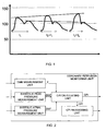
- the coronary perfusion index CPI is constructed to both monitor the supply and demand side of coronary circulation and should be as high as possible.
- the systolic arterial pressure SAP is a measure of demand, while the diastolic peak pressure DPP is a measure of blood supply.
- the time t is a measure of the "biological age" of the cardiovascular system.
- the above measures used to calculate CPI may be determined in a number of different ways.
- one or many of the measures are determined by use of impedance measurements.
- one or many of the measures are determined by use of blood pressure measurements.
- one or many of the measures are determined by a combination of different measurement techniques, e.g. by measuring blood pressure, impedance, blood flow, heart sound or electrical heart potentials.
- the CPI may be used for diagnosis or for therapy management.
- the therapy (pacing, drug management / titration, etc.) could then be adjusted to maximize CPI.
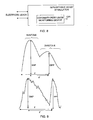
- FIG. 2 showing a block diagram of the implantable coronary perfusion monitoring device according to the present invention, the overall concept of the present invention will be discussed.
- the present invention relates to an implantable coronary perfusion monitoring device for in-vivo determination of a coronary perfusion index ( CPI ) indicative of the coronary perfusion of a heart.
- CPI coronary perfusion index
- the device comprises a systolic arterial pressure measurement unit adapted to determine a systolic arterial blood pressure measure SAP related to systolic arterial pressure; a diastolic peak pressure measurement unit adapted to determine a diastolic peak blood pressure measure DPP related to diastolic aortic peak pressure, and a time measurement unit to determine a blood pressure reflection wave measure t indicating the timely position in the heart cycle of the maximum of a reflected blood pressure wave and being a time period starting at a preset point of time in systole and ending at a local maximum of blood pressure following aortic valve closure.
- a coronary perfusion index calculating unit is provided adapted to determine said coronary perfusion index CPI as ( t ⁇ DPP) / SAP.
- the coronary perfusion index CPI is calculated by using three parameters t, DPP and SAP.
- the blood pressure reflection wave measure t is a time period starting at a preset point of time in systole and ending at a local maximum of blood pressure following aortic valve closure.
- Figure 3 is a block diagram illustrating different embodiments for determining a time measure in accordance with the present invention.
- a number of different measurement units is disclosed, but it should be understood that, in use, preferably, one or two units are used. Two units may be used if different measurement techniques are used to detect the start and the end of the time period.
- an impedance measurement unit is used to determine the blood pressure reflection wave measure t by identifying specified parts of impedance waveforms obtained by the impedance measurement unit.
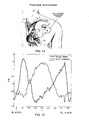
- the upper curve of figure 9 schematically illustrates the aortic blood pressure close to the aortic valve.
- the lower curve illustrates an impedance signal obtained by the set up illustrated in figure 11 .
- FIG 11 is shown how the impedance is recorded between the electrodes in the right atrium and the pacemaker can be in order to monitor the aortic valve closure, for instance tripolar impedance configuration using the RA-ring and RA-tip in connection with the device can (capsule or housing) as nodes for current injection and voltage sensing.
- the resulting voltage which is measured during injection of the excitation current will be across the aorta and that the resulting impedance signal contains information pertaining to the aorta.
- tripolar impedance measuring aortic properties is displayed together with impedance waveform using a right ventricle-left ventricle quadropolar configuration. This latter configuration is predominantly acquiring left ventricular properties. As can be expected, the tripolar impedance measuring aortic properties is in opposite phase when compared to an impedance measurement monitoring the left ventricle for instance.
- the solid line represents the impedance discussed above, whereas the dashed impedance waveform represents a more "standard" intracardiac impedance, e.g. obtained between electrodes in right and left ventricles.
- the dashed waveform will increase during systole as blood is ejected from the heart and decrease as blood returns during diastole, due to the higher conductivity of blood than the surrounding tissue..In the case with the impedance discussed in relation to the present invention is the opposite. This would suggest that we measure an increased blood volume during systole. Thus, this observation in connection with the information from figure 11 is a strong indication that in fact the aorta is measured.
- aortic pressure curve close to the aortic valve is shown.
- the aortic valve is open.
- the left ventricle relaxes and the valve is closed.
- the connections to the aorta of the two coronary arteries are situated in aorta close to the aortic valve.
- Flow in the coronary arteries supplying the left ventricle is close to zero during systole due to high wall tension and collapse of small intramyocardial blood vessels. The diastolic pressure is therefore of great importance for myocardial vascular supply.
- the time period ends at the local maximum of blood pressure following aortic valve closure, which is determined from the invested impedance curve form as the point of time of the second maximum of the inverted impedance waveform, which is illustrated in figure 9 .
- the preset point of time starting the time period is, according to one embodiment, the point in time where the first maximum of the inverted impedance waveform (d(-Z)/dt) occurs following the R-wave, where Z is the impedance measured by the impedance measurement unit.
- the time period length determined according to this embodiment is denoted t '.
- Figures 10a-10c show further examples of impedance curves were t, t', SAP and DDP are indicated.
- the impedance curve shown in figure 10c is obtained by applying the current between the ring electrode in the right atrium and the housing of the pacemaker (the case), and the voltage is sensed between the tip electrode in the right atrium and the case.
- a blood pressure measurement unit is used to determine the blood pressure reflection wave measure t by identifying specified parts of pressure waveforms obtained by that unit.
- the time period ends at the point of time of the second arterial pressure maximum of the reflected wave following aorta valve closure.
- the preset point of time starting the time period is the point of time where the maximum of dLVP/dt occurs, where LVP is the blood pressure in the left ventricle measured by the blood pressure measurement unit.
- the preset point of time starting the time period is the time of opening of the aortic valve following an R-wave.
- closure of the AV-valves i.e. the mitralis and/or tricuspidalis valves, may be used as starting points.
- the point of time of opening and/or closing of the valves is in one embodiment determined by using a heart sound measurement unit. If measuring the closure of the AV-valves preferably the first heart tone (S1) is used.
- the point of time of opening of the aortic valve is determined by using a blood flow measurement unit adapted to measure the blood flow in the left ventricle or in the arterial system. The time period then ends at the point of time at which a second maximum is sensed going in the other direction compared to the direction of the primary pulse started by the mechanical systole.
- the time of opening of the aortic valve following the R-wave may as an alternative be determined by using a pulseplethysmography (PPG) measurement unit adapted to measure the onset of blood flow following the onset of electrical systole, and that the time period ends at the point of time of a second maximum detectable in a PPG-signal detected by said PPG measurement unit.
- PPG pulseplethysmography
- the preset point of time starting the time period is the point of time for the R-wave using an IEGM detecting unit.
- the time period in this case is indicated by t in the upper curve of figure 9 .
- a further alternative is to use as a starting point the point in time coinciding with the first pressure maximum, or inverted impedance maximum, following the R-wave.
- t becomes negative which may be the case of very quick reflecting pressure waves.
- an indirect measure of t may also be obtained through an estimate of vessel elasticity.
- An increased elasticity in the arterial system of the patient will inevitably lead to a prolongation of t, whereas a decrease in elasticity will cause a faster return of the reflected pressure wave, causing a decrease in t.
- a blood pressure measurement unit is arranged in accordance with one embodiment of the present invention. This is schematically illustrated in figure 6 .
- the blood pressure measurement unit is adapted to measure the blood pressure in the arterial system close to the aortic valve, and by determining DPP as the peak-to-peak value for the second maximum in the heart cycle from obtained pressure signals which is shown in the upper curve of figure 9 .
- the blood pressure measurement unit is adapted to measure the blood pressure in the arterial system close to the aortic valve, and to determine DPP by integration of the pressure signal waveform during diastole.
- the device comprises an impedance measurement unit adapted to determine the DPP as the amplitude of the local maximum of the impedance during diastole.
- a block diagram of this embodiment is shown in figure 4 , and in the lower curve of figure 9 is indicated how to identify DPP from the impedance curve.
- figure 13 shows an impedance waveform where DPP is determined by identifying the peak to peak impedance value during diastole, indicated in the figure as ⁇ Z v . For example by performing a peak-to-peak calculation in a given window after a detected R-wave.
- Still another possibility is to use photoplethysmography or impedance in direct connection to the main coronary arteries as approximation for DPP, considering that the DPP is supposed to be a measure of blood supply to the heart itself.
- Another alternative is to use a flow sensor in connection to the main coronary artery and then detecting the peak value.
- the systolic arterial pressure SAP is the absolute blood pressure above atmospheric pressure. SAP is determined most effectively by using a pressure sensor in the arterial system, preferably close to the aortic valve.
- the implantable coronary perfusion monitoring device comprises a blood pressure measurement unit adapted to measure the blood pressure in the arterial system in the aorta or in the left ventricle, and that determines SAP as the first maximum pressure value following the onset of electrical systole.
- a block diagram illustrating this embodiment is shown in figure 7 .
- the upper curve of figure 9 illustrates how SAP is determined from the pressure curve.
- SAP may be calculated by integrating the waveform during systole.
- the device comprises an impedance measurement unit adapted to determine the SAP as the first maximum peak to peak value of the inverted impedance signal, occurring after onset of electrical systole.
- an impedance measurement unit adapted to determine the SAP as the first maximum peak to peak value of the inverted impedance signal, occurring after onset of electrical systole. This embodiment is illustrated by the block diagram in figure 6 and indicated in the lower curve in figure 9 .
- a photoplethysmography sensor may be used which has the benefit that it does not need to be arranged in the arterial system, but only adjacent to it.
- pulsating blood flow SAP may be determined.
- the CPI values may be calculated at regular intervals, or upon request, and in that regard the device further comprises a CPI processing unit adapted to store calculated CPI values in order to e.g. identify long term trends of the CPI values.
- the CPI processing unit may e.g. be provided with one or many threshold values indicative of specific perfusion states.
- the CPI processing unit may then be adapted to generate CPI alert signals in dependence of the CPI values relation to the threshold or thresholds.
- One preferred implementation of the implantable coronary perfusion monitoring device is to arranged the device in connection to an implantable heart stimulator provided with one or many electrode leads adapted to apply stimulation therapy to the heart.
- the CPI processing unit is adapted to detect variations of the CPI values as a result of variation of the stimulation therapy and then being able to optimize the stimulation therapy such that the CPI is as high as possible.
- the implantable heart stimulator including the coronary perfusion monitoring device is naturally provided with all necessary means required to perform its intended stimulation therapy.
- telemetry means which enables bidirectional wireless communication between the stimulator and an external programming device. It is then possible, in addition to all other information sent to, and received from, the stimulator to also include CPI values and values related to CPI values.
Landscapes
- Health & Medical Sciences (AREA)
- Life Sciences & Earth Sciences (AREA)
- Cardiology (AREA)
- Heart & Thoracic Surgery (AREA)
- Molecular Biology (AREA)
- Veterinary Medicine (AREA)
- Biophysics (AREA)
- Pathology (AREA)
- Engineering & Computer Science (AREA)
- Biomedical Technology (AREA)
- Public Health (AREA)
- Medical Informatics (AREA)
- Physics & Mathematics (AREA)
- Surgery (AREA)
- Animal Behavior & Ethology (AREA)
- General Health & Medical Sciences (AREA)
- Physiology (AREA)
- Vascular Medicine (AREA)
- Nuclear Medicine, Radiotherapy & Molecular Imaging (AREA)
- Radiology & Medical Imaging (AREA)
- Hematology (AREA)
- Measuring Pulse, Heart Rate, Blood Pressure Or Blood Flow (AREA)
Claims (20)
- Dispositif de surveillance de perfusion coronaire implantable destiné à la détermination in vivo d'un index de perfusion coronaire, c'est-à-dire CPI, indiquant la perfusion coronaire d'un coeur, ledit dispositif comprend
une unité de mesure de la pression artérielle systolique adaptée pour déterminer une mesure de pression sanguine artérielle systolique, c'est-à-dire SAP, en rapport avec la pression artérielle systolique ;
une unité de mesure de la pointe de pression diastolique adaptée pour déterminer une mesure de la pointe de pression artérielle diastolique, c'est-à-dire DPP, en rapport avec la pointe de pression aortique diastolique représentant une onde de pression artérielle réfléchie ;
une unité de mesure du temps destinée à déterminer une mesure d'onde de réflexion de pression artérielle, c'est-à-dire t, indiquant la position dans le temps dans le cycle cardiaque du maximum d'une onde de pression artérielle réfléchie et qui est une période de temps commençant à un moment prédéfini en systole et se terminant à un maximum local de pression artérielle suivant la fermeture de la valve aortique, et
une unité de calcul de l'index de perfusion coronaire adaptée pour déterminer ledit index de perfusion coronaire CPI en tant que (t • DPP) / SAP. - Dispositif de surveillance de perfusion coronaire implantable selon la revendication 1, comprenant une unité de mesure d'impédance, dans lequel ladite mesure d'onde de réflexion de pression artérielle t est déterminée en identifiant des parties spécifiées de formes d'onde d'impédance obtenues par l'unité de mesure d'impédance.
- Dispositif de surveillance de perfusion coronaire implantable selon la revendication 2, dans lequel ledit moment prédéfini commençant la période de temps est le moment où le premier d(-Z)/dt maximal se produit suivant l'onde R, où Z est l'impédance mesurée par l'unité de mesure d'impédance.
- Dispositif de surveillance de perfusion coronaire implantable selon la revendication 2, dans lequel ladite période de temps se termine au moment du second maximum de la forme d'onde d'impédance inversée.
- Dispositif de surveillance de perfusion coronaire implantable selon la revendication 1, comprenant une unité de mesure de pression artérielle et que ladite mesure d'onde de réflexion de pression artérielle t est déterminée en identifiant des parties spécifiées, représentant des parties de début et de fin de la période de temps, de formes d'onde de pression obtenues par l'unité de mesure de pression artérielle.
- Dispositif de surveillance de perfusion coronaire implantable selon la revendication 5, dans lequel ledit moment prédéfini commençant la période de temps est le moment où le maximum de dLVP/dt se produit, où LVP est la pression artérielle dans le ventricule gauche mesurée par ladite unité de mesure de pression artérielle.
- Dispositif de surveillance de perfusion coronaire implantable selon la revendication 5, dans lequel ladite période de temps se termine au moment du second maximum de la pression artérielle dans l'onde réfléchie suivant la fermeture de la valve aortique.
- Dispositif de surveillance de perfusion coronaire implantable selon la revendication 1, dans lequel ledit moment prédéfini commençant la période de temps est le moment de l'ouverture de la valve aortique suivant une onde R.
- Dispositif de surveillance de perfusion coronaire implantable selon la revendication 8, dans lequel le moment de l'ouverture de la valve aortique est déterminé en utilisant une unité de mesure du bruit cardiaque.
- Dispositif de surveillance de perfusion coronaire implantable selon la revendication 8, dans lequel le moment de l'ouverture de la valve aortique est déterminé en utilisant une unité de mesure de débit sanguin adaptée pour mesurer le débit sanguin dans le ventricule gauche ou dans le système artériel.
- Dispositif de surveillance de perfusion coronaire implantable selon la revendication 10, dans lequel ladite période de temps se termine au moment auquel un second maximum est détecté en allant dans l'autre direction par rapport à la direction de l'impulsion primaire commencée par la systole mécanique.
- Dispositif de surveillance de perfusion coronaire implantable selon la revendication 2, dans lequel le moment d'ouverture de la valve aortique suivant l'onde R est déterminé en utilisant une unité de mesure de pléthysmographie du pouls, c'est-à-dire PPG, adaptée pour mesurer le début du débit sanguin suivant le début de la systole électrique.
- Dispositif de surveillance de perfusion coronaire implantable selon la revendication 12, dans lequel ladite période de temps se termine au moment d'un second maximum détectable dans un signal de PPG détecté par ladite unité de mesure de PPG.
- Dispositif de surveillance de perfusion coronaire implantable selon la revendication 1, dans lequel ledit moment prédéfini commençant la période de temps est le moment de l'onde R en utilisant une unité de détection à électrocardiogramme endocavitaire.
- Dispositif de surveillance de perfusion coronaire implantable selon l'une quelconque des revendications 1 à 14, dans lequel le dispositif comprend une unité de mesure de pression artérielle adaptée pour mesurer la pression artérielle dans le système artériel proche de la valve aortique, et en déterminant la DPP en tant que valeur de crête à crête pour le second maximum dans le cycle cardiaque à partir de signaux de pression obtenus.
- Dispositif de surveillance de perfusion coronaire implantable selon l'une quelconque des revendications 1 à 14, dans lequel le dispositif comprend une unité de mesure de pression artérielle adaptée pour mesurer la pression artérielle dans le système artériel proche de la valve aortique, et en déterminant la DPP par intégration du signal de pression pendant la diastole.
- Dispositif de surveillance de perfusion coronaire implantable selon l'une quelconque des revendications 1 à 14, dans lequel le dispositif comprend une unité de mesure d'impédance adaptée pour déterminer la DPP en tant qu'amplitude du maximum local de l'impédance pendant la diastole.
- Dispositif de surveillance de perfusion coronaire implantable selon l'une quelconque des revendications 1 à 14, dans lequel le dispositif comprend une unité de mesure de pression artérielle adaptée pour mesurer la pression artérielle dans le système artériel dans l'aorte ou dans le ventricule gauche, et en déterminant la SAP en tant que la valeur de pression du premier maximum suivant le début de la systole électrique.
- Dispositif de surveillance de perfusion coronaire implantable selon l'une quelconque des revendications 1 à 14, dans lequel le dispositif comprend une unité de mesure d'impédance adaptée pour déterminer la SAP en tant que valeur de crête à crête du premier maximum du signal d'impédance inversé, se produisant après le début de la systole électrique.
- Dispositif de surveillance de perfusion coronaire implantable selon une quelconque revendication précédente, dans lequel ledit dispositif comprend en outre une unité de traitement de CPI adaptée pour enregistrer des valeurs de CPI calculées et pour identifier des tendances à long terme des valeurs de CPI.
Applications Claiming Priority (1)
| Application Number | Priority Date | Filing Date | Title |
|---|---|---|---|
| PCT/SE2009/000223 WO2010126404A1 (fr) | 2009-04-29 | 2009-04-29 | Dispositif de surveillance de perfusion coronaire implantable |
Publications (3)
| Publication Number | Publication Date |
|---|---|
| EP2424428A1 EP2424428A1 (fr) | 2012-03-07 |
| EP2424428A4 EP2424428A4 (fr) | 2013-03-27 |
| EP2424428B1 true EP2424428B1 (fr) | 2015-03-04 |
Family
ID=43032371
Family Applications (1)
| Application Number | Title | Priority Date | Filing Date |
|---|---|---|---|
| EP09844109.0A Not-in-force EP2424428B1 (fr) | 2009-04-29 | 2009-04-29 | Dispositif de surveillance de perfusion coronaire implantable |
Country Status (3)
| Country | Link |
|---|---|
| US (1) | US8690787B2 (fr) |
| EP (1) | EP2424428B1 (fr) |
| WO (1) | WO2010126404A1 (fr) |
Families Citing this family (12)
| Publication number | Priority date | Publication date | Assignee | Title |
|---|---|---|---|---|
| US8403983B2 (en) | 2008-09-29 | 2013-03-26 | Cardiaq Valve Technologies, Inc. | Heart valve |
| EP2845569A1 (fr) | 2008-10-01 | 2015-03-11 | Cardiaq Valve Technologies, Inc. | Système d'administration pour implant vasculaire |
| CA2756049C (fr) | 2009-04-15 | 2017-05-02 | Impala, Inc. | Implant vasculaire et systeme d'introduction |
| US8579964B2 (en) | 2010-05-05 | 2013-11-12 | Neovasc Inc. | Transcatheter mitral valve prosthesis |
| US9308087B2 (en) | 2011-04-28 | 2016-04-12 | Neovasc Tiara Inc. | Sequentially deployed transcatheter mitral valve prosthesis |
| US9554897B2 (en) | 2011-04-28 | 2017-01-31 | Neovasc Tiara Inc. | Methods and apparatus for engaging a valve prosthesis with tissue |
| US9345573B2 (en) | 2012-05-30 | 2016-05-24 | Neovasc Tiara Inc. | Methods and apparatus for loading a prosthesis onto a delivery system |
| US10583002B2 (en) | 2013-03-11 | 2020-03-10 | Neovasc Tiara Inc. | Prosthetic valve with anti-pivoting mechanism |
| US9681951B2 (en) | 2013-03-14 | 2017-06-20 | Edwards Lifesciences Cardiaq Llc | Prosthesis with outer skirt and anchors |
| US9572665B2 (en) | 2013-04-04 | 2017-02-21 | Neovasc Tiara Inc. | Methods and apparatus for delivering a prosthetic valve to a beating heart |
| US11116456B2 (en) | 2019-06-27 | 2021-09-14 | Medtronic, Inc. | Sensing for heart failure management |
| CN117281494B (zh) * | 2023-11-27 | 2024-03-12 | 安徽通灵仿生科技有限公司 | 一种动脉血压信号的信号特征点识别方法及装置 |
Family Cites Families (10)
| Publication number | Priority date | Publication date | Assignee | Title |
|---|---|---|---|---|
| US4834107A (en) | 1984-05-10 | 1989-05-30 | Sylvia Warner | Heart-related parameters monitoring apparatus |
| IL77677A (en) * | 1986-01-22 | 1990-04-29 | Daniel Goor | Method and apparatus for detecting mycardial ischemia |
| US5054493A (en) | 1986-01-31 | 1991-10-08 | Regents Of The University Of Minnesota | Method for diagnosing, monitoring and treating hypertension |
| US5211177A (en) | 1990-12-28 | 1993-05-18 | Regents Of The University Of Minnesota | Vascular impedance measurement instrument |
| US5766127A (en) * | 1996-04-15 | 1998-06-16 | Ohmeda Inc. | Method and apparatus for improved photoplethysmographic perfusion-index monitoring |
| EP0870466B1 (fr) * | 1997-04-12 | 1999-06-02 | Hewlett-Packard Company | Procédé et dispositif pour déterminer la concentration d'un constituant |
| US6315735B1 (en) | 1999-03-31 | 2001-11-13 | Pulsion Medical Systems Ag | Devices for in-vivo determination of the compliance function and the systemic blood flow of a living being |
| US7951129B2 (en) * | 2003-08-07 | 2011-05-31 | Medtronic, Inc. | Diastolic coronary perfusion detection for timed delivery of therapeutic and/or diagnostic agents |
| EP1518560A1 (fr) | 2003-09-26 | 2005-03-30 | Aga Ab | Utilisation d'un gaz pour l'obtention d'un agent diagnostique pour la diagnose de la perfusion coronaire |
| US20090275854A1 (en) | 2008-04-30 | 2009-11-05 | Zielinski Todd M | System and method of monitoring physiologic parameters based on complex impedance waveform morphology |
-
2009
- 2009-04-29 US US13/265,722 patent/US8690787B2/en active Active
- 2009-04-29 EP EP09844109.0A patent/EP2424428B1/fr not_active Not-in-force
- 2009-04-29 WO PCT/SE2009/000223 patent/WO2010126404A1/fr active Application Filing
Also Published As
| Publication number | Publication date |
|---|---|
| EP2424428A4 (fr) | 2013-03-27 |
| WO2010126404A1 (fr) | 2010-11-04 |
| EP2424428A1 (fr) | 2012-03-07 |
| US8690787B2 (en) | 2014-04-08 |
| US20120083703A1 (en) | 2012-04-05 |
Similar Documents
| Publication | Publication Date | Title |
|---|---|---|
| EP2424428B1 (fr) | Dispositif de surveillance de perfusion coronaire implantable | |
| US10863907B2 (en) | Method and apparatus for the non-invasive measurement of pulse transit times (PTT) | |
| Dehkordi et al. | Comparison of different methods for estimating cardiac timings: a comprehensive multimodal echocardiography investigation | |
| US7899526B2 (en) | Portable device for monitoring electrocardiographic signals and indices of blood flow | |
| EP2528499B1 (fr) | Elimination des effets de cycles cardiaques irréguliers lors de la détermination de paramètres cardiovasculaires | |
| US8162841B2 (en) | Standalone systemic arterial blood pressure monitoring device | |
| US7615011B2 (en) | Method and apparatus for measuring blood volume, and vital sign monitor using the same | |
| JP5985355B2 (ja) | 血液量測定方法および測定装置 | |
| US8428698B2 (en) | Systems and methods for monitoring DP, IVRT, DiFT, diastolic function and/or HF | |
| US8632470B2 (en) | Assessment of pulmonary vascular resistance via pulmonary artery pressure | |
| US20100268101A1 (en) | Method and apparatus for measuring blood volume | |
| EP1690566A1 (fr) | Détecteur d' ischémie | |
| US8812093B2 (en) | Systems and methods for exploiting near-field impedance and admittance for use with implantable medical devices | |
| US20060135871A1 (en) | Method for measurement of systolic and diastolic time intervals | |
| ITBO20100105A1 (it) | Dispositivo per la quantificazione e il monitoraggio della funzione cardiovascolare in corso di stress o attivita' fisica e a riposo | |
| US8112150B2 (en) | Optimization of pacemaker settings | |
| Ragosta et al. | Normal waveforms, artifacts, and pitfalls | |
| Jasińska-Gniadzik et al. | Haemodynamic monitoring in acute heart failure–what you need to know | |
| US11666230B1 (en) | Electronic device and method for noninvasive, continuous blood pressure monitoring | |
| WO2017137983A1 (fr) | Système et procédé permettant de surveiller les paramètres cardiaques de manière non invasive | |
| JP6304749B2 (ja) | 循環動態監視装置 | |
| Hettrick et al. | Human feasibility study of hemodynamic monitoring via continuous intrathoracic impedance monitoring | |
| Ripoli et al. | NON-INVASIVE BLOOD PRESSURE MEASUREMENT APPROACH FOR CONTINUOUS AMBULATORY MONITORING |
Legal Events
| Date | Code | Title | Description |
|---|---|---|---|
| PUAI | Public reference made under article 153(3) epc to a published international application that has entered the european phase |
Free format text: ORIGINAL CODE: 0009012 |
|
| 17P | Request for examination filed |
Effective date: 20111129 |
|
| AK | Designated contracting states |
Kind code of ref document: A1 Designated state(s): AT BE BG CH CY CZ DE DK EE ES FI FR GB GR HR HU IE IS IT LI LT LU LV MC MK MT NL NO PL PT RO SE SI SK TR |
|
| DAX | Request for extension of the european patent (deleted) | ||
| A4 | Supplementary search report drawn up and despatched |
Effective date: 20130226 |
|
| RIC1 | Information provided on ipc code assigned before grant |
Ipc: A61B 5/0215 20060101AFI20130220BHEP Ipc: A61B 5/021 20060101ALI20130220BHEP Ipc: A61B 5/026 20060101ALI20130220BHEP Ipc: A61B 5/02 20060101ALI20130220BHEP Ipc: A61B 5/053 20060101ALI20130220BHEP Ipc: A61B 5/0295 20060101ALI20130220BHEP |
|
| GRAP | Despatch of communication of intention to grant a patent |
Free format text: ORIGINAL CODE: EPIDOSNIGR1 |
|
| INTG | Intention to grant announced |
Effective date: 20141002 |
|
| GRAS | Grant fee paid |
Free format text: ORIGINAL CODE: EPIDOSNIGR3 |
|
| GRAA | (expected) grant |
Free format text: ORIGINAL CODE: 0009210 |
|
| AK | Designated contracting states |
Kind code of ref document: B1 Designated state(s): AT BE BG CH CY CZ DE DK EE ES FI FR GB GR HR HU IE IS IT LI LT LU LV MC MK MT NL NO PL PT RO SE SI SK TR |
|
| REG | Reference to a national code |
Ref country code: GB Ref legal event code: FG4D |
|
| REG | Reference to a national code |
Ref country code: CH Ref legal event code: EP |
|
| REG | Reference to a national code |
Ref country code: IE Ref legal event code: FG4D |
|
| REG | Reference to a national code |
Ref country code: CH Ref legal event code: NV Representative=s name: E. BLUM AND CO. AG PATENT- UND MARKENANWAELTE , CH |
|
| REG | Reference to a national code |
Ref country code: AT Ref legal event code: REF Ref document number: 713103 Country of ref document: AT Kind code of ref document: T Effective date: 20150415 |
|
| REG | Reference to a national code |
Ref country code: DE Ref legal event code: R096 Ref document number: 602009029872 Country of ref document: DE Effective date: 20150416 |
|
| REG | Reference to a national code |
Ref country code: AT Ref legal event code: MK05 Ref document number: 713103 Country of ref document: AT Kind code of ref document: T Effective date: 20150304 Ref country code: NL Ref legal event code: VDEP Effective date: 20150304 |
|
| PG25 | Lapsed in a contracting state [announced via postgrant information from national office to epo] |
Ref country code: NO Free format text: LAPSE BECAUSE OF FAILURE TO SUBMIT A TRANSLATION OF THE DESCRIPTION OR TO PAY THE FEE WITHIN THE PRESCRIBED TIME-LIMIT Effective date: 20150604 Ref country code: SE Free format text: LAPSE BECAUSE OF FAILURE TO SUBMIT A TRANSLATION OF THE DESCRIPTION OR TO PAY THE FEE WITHIN THE PRESCRIBED TIME-LIMIT Effective date: 20150304 Ref country code: HR Free format text: LAPSE BECAUSE OF FAILURE TO SUBMIT A TRANSLATION OF THE DESCRIPTION OR TO PAY THE FEE WITHIN THE PRESCRIBED TIME-LIMIT Effective date: 20150304 Ref country code: LT Free format text: LAPSE BECAUSE OF FAILURE TO SUBMIT A TRANSLATION OF THE DESCRIPTION OR TO PAY THE FEE WITHIN THE PRESCRIBED TIME-LIMIT Effective date: 20150304 Ref country code: ES Free format text: LAPSE BECAUSE OF FAILURE TO SUBMIT A TRANSLATION OF THE DESCRIPTION OR TO PAY THE FEE WITHIN THE PRESCRIBED TIME-LIMIT Effective date: 20150304 Ref country code: FI Free format text: LAPSE BECAUSE OF FAILURE TO SUBMIT A TRANSLATION OF THE DESCRIPTION OR TO PAY THE FEE WITHIN THE PRESCRIBED TIME-LIMIT Effective date: 20150304 |
|
| REG | Reference to a national code |
Ref country code: LT Ref legal event code: MG4D |
|
| PG25 | Lapsed in a contracting state [announced via postgrant information from national office to epo] |
Ref country code: AT Free format text: LAPSE BECAUSE OF FAILURE TO SUBMIT A TRANSLATION OF THE DESCRIPTION OR TO PAY THE FEE WITHIN THE PRESCRIBED TIME-LIMIT Effective date: 20150304 Ref country code: GR Free format text: LAPSE BECAUSE OF FAILURE TO SUBMIT A TRANSLATION OF THE DESCRIPTION OR TO PAY THE FEE WITHIN THE PRESCRIBED TIME-LIMIT Effective date: 20150605 Ref country code: LV Free format text: LAPSE BECAUSE OF FAILURE TO SUBMIT A TRANSLATION OF THE DESCRIPTION OR TO PAY THE FEE WITHIN THE PRESCRIBED TIME-LIMIT Effective date: 20150304 |
|
| PG25 | Lapsed in a contracting state [announced via postgrant information from national office to epo] |
Ref country code: NL Free format text: LAPSE BECAUSE OF FAILURE TO SUBMIT A TRANSLATION OF THE DESCRIPTION OR TO PAY THE FEE WITHIN THE PRESCRIBED TIME-LIMIT Effective date: 20150304 |
|
| PG25 | Lapsed in a contracting state [announced via postgrant information from national office to epo] |
Ref country code: RO Free format text: LAPSE BECAUSE OF FAILURE TO SUBMIT A TRANSLATION OF THE DESCRIPTION OR TO PAY THE FEE WITHIN THE PRESCRIBED TIME-LIMIT Effective date: 20150304 Ref country code: PT Free format text: LAPSE BECAUSE OF FAILURE TO SUBMIT A TRANSLATION OF THE DESCRIPTION OR TO PAY THE FEE WITHIN THE PRESCRIBED TIME-LIMIT Effective date: 20150706 Ref country code: EE Free format text: LAPSE BECAUSE OF FAILURE TO SUBMIT A TRANSLATION OF THE DESCRIPTION OR TO PAY THE FEE WITHIN THE PRESCRIBED TIME-LIMIT Effective date: 20150304 Ref country code: SK Free format text: LAPSE BECAUSE OF FAILURE TO SUBMIT A TRANSLATION OF THE DESCRIPTION OR TO PAY THE FEE WITHIN THE PRESCRIBED TIME-LIMIT Effective date: 20150304 Ref country code: CZ Free format text: LAPSE BECAUSE OF FAILURE TO SUBMIT A TRANSLATION OF THE DESCRIPTION OR TO PAY THE FEE WITHIN THE PRESCRIBED TIME-LIMIT Effective date: 20150304 |
|
| PG25 | Lapsed in a contracting state [announced via postgrant information from national office to epo] |
Ref country code: MC Free format text: LAPSE BECAUSE OF FAILURE TO SUBMIT A TRANSLATION OF THE DESCRIPTION OR TO PAY THE FEE WITHIN THE PRESCRIBED TIME-LIMIT Effective date: 20150304 Ref country code: IS Free format text: LAPSE BECAUSE OF FAILURE TO SUBMIT A TRANSLATION OF THE DESCRIPTION OR TO PAY THE FEE WITHIN THE PRESCRIBED TIME-LIMIT Effective date: 20150704 Ref country code: PL Free format text: LAPSE BECAUSE OF FAILURE TO SUBMIT A TRANSLATION OF THE DESCRIPTION OR TO PAY THE FEE WITHIN THE PRESCRIBED TIME-LIMIT Effective date: 20150304 |
|
| REG | Reference to a national code |
Ref country code: DE Ref legal event code: R097 Ref document number: 602009029872 Country of ref document: DE |
|
| PLBE | No opposition filed within time limit |
Free format text: ORIGINAL CODE: 0009261 |
|
| STAA | Information on the status of an ep patent application or granted ep patent |
Free format text: STATUS: NO OPPOSITION FILED WITHIN TIME LIMIT |
|
| REG | Reference to a national code |
Ref country code: IE Ref legal event code: MM4A |
|
| PG25 | Lapsed in a contracting state [announced via postgrant information from national office to epo] |
Ref country code: DK Free format text: LAPSE BECAUSE OF FAILURE TO SUBMIT A TRANSLATION OF THE DESCRIPTION OR TO PAY THE FEE WITHIN THE PRESCRIBED TIME-LIMIT Effective date: 20150304 |
|
| 26N | No opposition filed |
Effective date: 20151207 |
|
| GBPC | Gb: european patent ceased through non-payment of renewal fee |
Effective date: 20150604 |
|
| PG25 | Lapsed in a contracting state [announced via postgrant information from national office to epo] |
Ref country code: SI Free format text: LAPSE BECAUSE OF FAILURE TO SUBMIT A TRANSLATION OF THE DESCRIPTION OR TO PAY THE FEE WITHIN THE PRESCRIBED TIME-LIMIT Effective date: 20150304 |
|
| REG | Reference to a national code |
Ref country code: FR Ref legal event code: PLFP Year of fee payment: 8 |
|
| PG25 | Lapsed in a contracting state [announced via postgrant information from national office to epo] |
Ref country code: GB Free format text: LAPSE BECAUSE OF NON-PAYMENT OF DUE FEES Effective date: 20150604 Ref country code: IE Free format text: LAPSE BECAUSE OF NON-PAYMENT OF DUE FEES Effective date: 20150429 |
|
| PG25 | Lapsed in a contracting state [announced via postgrant information from national office to epo] |
Ref country code: BE Free format text: LAPSE BECAUSE OF FAILURE TO SUBMIT A TRANSLATION OF THE DESCRIPTION OR TO PAY THE FEE WITHIN THE PRESCRIBED TIME-LIMIT Effective date: 20150304 |
|
| PG25 | Lapsed in a contracting state [announced via postgrant information from national office to epo] |
Ref country code: MT Free format text: LAPSE BECAUSE OF FAILURE TO SUBMIT A TRANSLATION OF THE DESCRIPTION OR TO PAY THE FEE WITHIN THE PRESCRIBED TIME-LIMIT Effective date: 20150304 |
|
| REG | Reference to a national code |
Ref country code: FR Ref legal event code: PLFP Year of fee payment: 9 |
|
| PG25 | Lapsed in a contracting state [announced via postgrant information from national office to epo] |
Ref country code: HU Free format text: LAPSE BECAUSE OF FAILURE TO SUBMIT A TRANSLATION OF THE DESCRIPTION OR TO PAY THE FEE WITHIN THE PRESCRIBED TIME-LIMIT; INVALID AB INITIO Effective date: 20090429 Ref country code: BG Free format text: LAPSE BECAUSE OF FAILURE TO SUBMIT A TRANSLATION OF THE DESCRIPTION OR TO PAY THE FEE WITHIN THE PRESCRIBED TIME-LIMIT Effective date: 20150304 |
|
| PG25 | Lapsed in a contracting state [announced via postgrant information from national office to epo] |
Ref country code: CY Free format text: LAPSE BECAUSE OF FAILURE TO SUBMIT A TRANSLATION OF THE DESCRIPTION OR TO PAY THE FEE WITHIN THE PRESCRIBED TIME-LIMIT Effective date: 20150304 |
|
| PG25 | Lapsed in a contracting state [announced via postgrant information from national office to epo] |
Ref country code: TR Free format text: LAPSE BECAUSE OF FAILURE TO SUBMIT A TRANSLATION OF THE DESCRIPTION OR TO PAY THE FEE WITHIN THE PRESCRIBED TIME-LIMIT Effective date: 20150304 |
|
| PG25 | Lapsed in a contracting state [announced via postgrant information from national office to epo] |
Ref country code: LU Free format text: LAPSE BECAUSE OF NON-PAYMENT OF DUE FEES Effective date: 20150429 |
|
| REG | Reference to a national code |
Ref country code: FR Ref legal event code: PLFP Year of fee payment: 10 |
|
| PG25 | Lapsed in a contracting state [announced via postgrant information from national office to epo] |
Ref country code: MK Free format text: LAPSE BECAUSE OF FAILURE TO SUBMIT A TRANSLATION OF THE DESCRIPTION OR TO PAY THE FEE WITHIN THE PRESCRIBED TIME-LIMIT Effective date: 20150304 |
|
| PGFP | Annual fee paid to national office [announced via postgrant information from national office to epo] |
Ref country code: CH Payment date: 20210318 Year of fee payment: 13 Ref country code: FR Payment date: 20210324 Year of fee payment: 13 |
|
| PGFP | Annual fee paid to national office [announced via postgrant information from national office to epo] |
Ref country code: IT Payment date: 20210415 Year of fee payment: 13 Ref country code: DE Payment date: 20210318 Year of fee payment: 13 |
|
| REG | Reference to a national code |
Ref country code: DE Ref legal event code: R119 Ref document number: 602009029872 Country of ref document: DE |
|
| REG | Reference to a national code |
Ref country code: CH Ref legal event code: PL |
|
| PG25 | Lapsed in a contracting state [announced via postgrant information from national office to epo] |
Ref country code: LI Free format text: LAPSE BECAUSE OF NON-PAYMENT OF DUE FEES Effective date: 20220430 Ref country code: FR Free format text: LAPSE BECAUSE OF NON-PAYMENT OF DUE FEES Effective date: 20220430 Ref country code: DE Free format text: LAPSE BECAUSE OF NON-PAYMENT OF DUE FEES Effective date: 20221103 Ref country code: CH Free format text: LAPSE BECAUSE OF NON-PAYMENT OF DUE FEES Effective date: 20220430 |
|
| PG25 | Lapsed in a contracting state [announced via postgrant information from national office to epo] |
Ref country code: IT Free format text: LAPSE BECAUSE OF NON-PAYMENT OF DUE FEES Effective date: 20220429 |
|
| P01 | Opt-out of the competence of the unified patent court (upc) registered |
Effective date: 20230602 |