EP2423823B1 - Methods and apparatus for improved host/initiator utilization in serial advanced technology attachment communication - Google Patents
Methods and apparatus for improved host/initiator utilization in serial advanced technology attachment communication Download PDFInfo
- Publication number
- EP2423823B1 EP2423823B1 EP11178910.3A EP11178910A EP2423823B1 EP 2423823 B1 EP2423823 B1 EP 2423823B1 EP 11178910 A EP11178910 A EP 11178910A EP 2423823 B1 EP2423823 B1 EP 2423823B1
- Authority
- EP
- European Patent Office
- Prior art keywords
- size
- data
- storage device
- switching device
- subcount
- Prior art date
- Legal status (The legal status is an assumption and is not a legal conclusion. Google has not performed a legal analysis and makes no representation as to the accuracy of the status listed.)
- Not-in-force
Links
Images


Classifications
-
- G—PHYSICS
- G06—COMPUTING; CALCULATING OR COUNTING
- G06F—ELECTRIC DIGITAL DATA PROCESSING
- G06F13/00—Interconnection of, or transfer of information or other signals between, memories, input/output devices or central processing units
- G06F13/14—Handling requests for interconnection or transfer
- G06F13/20—Handling requests for interconnection or transfer for access to input/output bus
- G06F13/28—Handling requests for interconnection or transfer for access to input/output bus using burst mode transfer, e.g. direct memory access DMA, cycle steal
-
- G—PHYSICS
- G06—COMPUTING; CALCULATING OR COUNTING
- G06F—ELECTRIC DIGITAL DATA PROCESSING
- G06F13/00—Interconnection of, or transfer of information or other signals between, memories, input/output devices or central processing units
- G06F13/14—Handling requests for interconnection or transfer
- G06F13/16—Handling requests for interconnection or transfer for access to memory bus
-
- G—PHYSICS
- G06—COMPUTING; CALCULATING OR COUNTING
- G06F—ELECTRIC DIGITAL DATA PROCESSING
- G06F2213/00—Indexing scheme relating to interconnection of, or transfer of information or other signals between, memories, input/output devices or central processing units
- G06F2213/0028—Serial attached SCSI [SAS]
-
- G—PHYSICS
- G06—COMPUTING; CALCULATING OR COUNTING
- G06F—ELECTRIC DIGITAL DATA PROCESSING
- G06F2213/00—Indexing scheme relating to interconnection of, or transfer of information or other signals between, memories, input/output devices or central processing units
- G06F2213/0032—Serial ATA [SATA]
Definitions
- the invention relates generally to storage system performance and more specifically relates to methods and apparatus for improving initiator performance in communications between a Serial Attached SCSI Serial Advanced Technology Attachment Tunneling Protocol (SAS/STP) initiator device and a plurality of SATA target devices through a Serial Attached SCSI (SAS) expander.
- SAS/STP Serial Attached SCSI Serial Advanced Technology Attachment Tunneling Protocol
- SAS Serial Attached SCSI
- a host system communicates with one or more storage devices.
- a SAS/STP initiator device e.g., a host system
- a SATA target device e.g., a SATA storage device such as a disk drive.
- a host system a native SATA host controller
- NCPQ SATA Native Command Queuing
- the SATA Device sends a DMA SETUP Frame Information Structure (FIS) to the SATA host to indicate that it is now ready to receive data from the host to the device.
- FIS Frame Information Structure
- the SATA protocol provides a mechanism for the device to use multiple DMA SETUP FISs to complete a large I/O (for example 500 megabytes)
- the SATA storage devices will choose to send a single DMA SETUP FIS for the entire I/O size (e.g., 500 megabytes as in the previous example).
- This capability is referred as Non-Zero Buffer Offset in the SATA specification. Since typical SATA disk drives do not provide sustained data transfer over such large volumes of data, this SATA standard technique results in large periods of stalling due to flow control signals/frames on the SATA interface.
- SAS Serial Attached SCSI
- STP Serial Attached SCSI Tunneling Protocol
- these periods of stalling can be wasteful in that they consume other SAS resources (particularly SAS connection pathways that could be used for other connections but for the stalled connection with one SATA device that has stalled the large DMA transfer).
- SAS Initiator or SATA host has no real knowledge of the SATA storage device's internal buffer state and therefore cannot intelligently determine how much data the drive can actually sustain.
- a SAS topology coupling a plurality of SATA storage devices to a SAS controller (e.g., through a SAS expander), the overall system performance is degraded by this SATA feature.
- US 2007/0136521 discloses a method according to the preamble of claim 1 and a device according to the preamble of claim 7.
- the present invention solves the above and other problems, thereby advancing the state of the useful arts, by providing methods and apparatus for enhanced performance in communications between a SAS/STP initiator and multiple SATA target devices through an enhanced SAS expander.
- the expander is enhanced in accordance with features and aspects hereof to receive a DMA SETUP FIS from a storage device and to transmit multiple modified DMA SETUP FISs to the SAS/STP initiator where each modified DMA SETUP FIS comprises a subcount less than the maximum count in the received DMA SETUP FIS.
- Another arrangement hereof provides a method operable in a SAS expander for transferring data from a SAS/STP initiator coupled with the expander to a SATA storage device of a plurality of SATA storage devices coupled with the expander.
- the method comprises receiving a Register FIS comprising a command (hereinafter also referred to as a "COMMAND FIS") from the SAS/STP initiator wherein the COMMAND FIS comprises an I/O request size indicating the size of data to be exchanged with the SATA storage device.
- the method then transmits the COMMAND FIS to the SATA storage device.
- the method also comprises a) receiving a DMA SETUP FIS from the SATA storage device.
- the DMA SETUP FIS comprises a maximum size of data that may be transferred to the SATA storage device in response to the DMA SETUP FIS.
- the method also comprises b) determining a subcount size less than the maximum size and c) transmitting a modified DMA SETUP FIS to the SAS/STP initiator wherein the modified DMA SETUP FIS comprises the subcount size.
- the method then comprises d) transferring data between the SAS/STP initiator and the SATA storage device wherein the amount of data forwarded is no greater than the subcount size.
- the method then comprises e) repeating steps b), c), and d) until the amount of data exchanged is equal to the maximum size or is equal to the I/O request size.
- the method also comprises repeating the steps of a), b), c), d), and e) until the amount of data exchanged is equal to the I/O request size.
- Yet another aspect hereof provides a switching device according to claim 7.
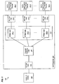
- FIG. 1 is a block diagram of a system 100 enhanced in accordance with features and aspects hereof to improve performance of the system in communications between an initiator device (e.g., a SATA host/initiator) and multiple SATA target devices through an enhanced switching device 104 (e.g., an enhanced SAS expander 104 in a SAS domain topology).
- Switching device 104 couples initiator 102 with a plurality of SATA target devices 106.1 through 106.n.
- Initiator 102 may be any device adapted for communicating with one or more SATA storage devices through an intermediate switching device.
- initiator 102 may be any device adapted for communications utilizing the SAS protocols and more specifically adapted for communications utilizing the SATA Tunneling Protocol (STP) of the SAS architecture.
- STP SATA Tunneling Protocol
- initiator 102 may be a SAS/STP initiator.
- SATA target devices 106.1 through 106.n may be any devices adapted to receive and process I/O requests in accordance with the SATA protocol.
- each SATA target device 106.1 through 106.n may be a SATA storage device such as a rotating magnetic or optical disk drive or a semi-conductor storage device such as a RAMdisk or flash memory storage device.
- Switching device 104 may be any device adapted to couple initiator 102 to any of a plurality of SATA storage devices 106.1 through 106.n.
- switching device 104 may be a SAS expander 104 comprising numerous standard components typical in any SAS expander. Such standard components may include, for example, front-end port logic 112 and back-end port logic 114.1 through 114.n.
- Front-end port logic 112 may be any circuit within the SAS expander 104 adapted to process physical and link layer aspects of the SAS protocols (as well as other layers of the protocols).
- back-end port logic 114.1 through 114.n each comprise any circuit within SAS expander 104 adapted to process physical and link layer aspects of the SAS and/or SATA protocols for coupling expander 104 with a plurality of SATA storage devices 106.1 through 106.n.
- crossbar switching logic 108 within SAS expander 104 comprises any suitable circuit for controllably switching SAS/STP initiator 102 (coupled through front-end port logic 112) to any of the SATA storage devices 106.1 through 106.n (through its corresponding back-end port logic circuits 114.1 through 114.n).
- SAS expander 104 is enhanced to comprise bridge logic 110 adapted for improving communication performance between SAS/STP initiator 102 and multiple SATA storage devices 106.1 through 106.n.
- SAS/STP initiator 102 may be logically connected to a single SATA storage device for the entire duration of a transfer having a maximum length indicated by a DMA SETUP FIS received from that SATA storage device.
- the maximum transfer length indicated by the DMA SETUP FIS indicates a maximum DMA transfer allowed from the SAS/STP initiator 102
- mechanical latency and other overhead processing issues within the SATA storage device 106.1 may temporarily pause the DMA transfer (using flow control features of the SAS protocol).
- bridge logic 110 of enhanced SAS expander 104 permits the SAS/STP initiator to process I/O requests directed to other SATA storage devices while a first SATA storage device may have paused a data transfer from the SAS/STP initiator 102.
- bridge logic 110 comprises bridge logic components 110.1 through 110.n each associated with a respective back-end port logic 114.1 through 114.n coupling the expander with a corresponding SATA storage device 106.1 through 106.n.
- Bridge logic 110 in operation receives a DMA SETUP FIS from a SATA storage device responsive to a COMMAND FIS sent to the storage device by SAS/STP initiator 102.
- the maximum original transfer size associated with the received DMA SETUP FIS is then broken into multiple modified DMA SETUP FISs each indicating a subcount less than the original maximum transfer size.
- These multiple modified DMA SETUP FIS are then transferred to SAS/STP initiator 102 to permit the initiator to process DMA transfers for I/O requests directed to other SATA storage devices between the multiple modified DMA SETUP FISs.
- bridge logic 110 may determine the subcount as a predetermined fixed buffer size.
- the predetermined fixed buffer size may be statically or dynamically configured at initialization or installation of expander 104.
- a manual process may be utilized by the system administrator in configuring the predetermined fixed buffer size based on heuristics and measured performance of the system and/or of the individual storage devices. Any number of factors may be considered in determining the predetermined fixed buffer size used for the subcount in each of the multiple modified DMA SETUP FISs to be transmitted to SAS/STP initiator 102.
- bridge logic 110 may comprise one or more buffer memories such that the subcount used in each modified DMA SETUP FIS is determined based on the size of the buffer memory in the bridge logic 110.
- each component bridge logic 110.1 through 110.n may comprise an associated buffer 200.1 through 200.n, respectively. The subcount used in such an embodiment is therefore determined based on the size of the buffer 200.1 through 200.n associated with bridge logic 110.1 through 110.n, respectively.
- bridge logic 110 may be devoid of such a buffer and determines the subcount used in each modified DMA SETUP FIS based on the size of a buffer within each SATA storage device 106.1 through 106.n. As shown in FIG. 3 , each bridge logic component 110.1 through 110.n may query SATA storage device 106.1 to determine the size of its respective buffer 300.1 through 300.n.
- switching device 104 may be any suitable device that couples any initiator device to any of a plurality of SATA storage devices.
- switching device 104 could be a Fibre Channel or Ethernet switch adapted to couple an initiator device to any of a plurality of SATA storage devices.
- initiator 102 need not be SAS/STP initiator device but rather could be any device for initiating contact with a target device.
- Switching device 104 could therefore also comprise protocol translation features for converting between protocols used between the switching device 104 and initiator 102 and protocols used between switching device 104 and the SATA storage devices 106.1 through 106.n.
- bridge logic 110 may be implemented as a single circuit component, as multiple bridge logic circuits (one for each back-end port), or may be integrated with other circuit component of switching device 104. Such design choices are well-known to those of ordinary skill in the art. Further, those of ordinary skill in the art will readily recognize that any number of port logic elements may be present in a fully functional switching device 104 as appropriate for the particular environment. Still further, switching device 104 may be coupled with any desired number of initiator devices and SATA storage devices as appropriate to the particular needs of the enterprise.
- FIG. 4 is a flowchart describing an exemplary method for improving communications between an initiator device and a plurality of SATA storage devices through an enhanced switching device (e.g., SAS expander) in accordance with features and aspects hereof.
- the method of FIG. 4 may be generally operable in enhanced SAS expander 104 of FIG. 1 and more specifically operable in conjunction with bridge logic 110 of enhanced SAS expander 104.
- an I/O request is received from the SAS/STP initiator.
- the received request is forwarded to the identified SATA storage device as an appropriate COMMAND FIS requesting that the storage device prepare for the indicated I/O request (e.g., a write command to be followed by a number of DATA FISs from the SAS/STP initiator to the SATA storage device when the device is ready to receive the data).
- the expander receives a first DMA SETUP FIS from the identified SATA storage device.
- the DMA SETUP FIS comprises a maximum count for the amount of data that may be transferred in a single DMA operation (e.g., the "original" count). This original count may be saved in a memory or register associated with the bridge logic corresponding to the SATA storage device from which the DMA SETUP FIS was received.
- a subcount is determined to be used for each of a plurality of modified DMA SETUP FISs to be sent to the SAS/STP initiator.
- the subcount may be determined as a predetermined fixed buffer size or may be determined based on the size of a buffer associated with the bridge logic and/or associated with the identified SATA storage device.
- a modified DMA SETUP FIS is sent to the SAS/STP initiator.
- the modified DMA SETUP FIS comprises the determined subcount (or a lesser remaining transfer count for the I/O request).
- the modified DMA SETUP FIS allows the SAS/STP initiator to prepare for a smaller DMA transfer such that the DMA circuits of the SAS/STP initiator (as well as any DMA circuits associated with the SAS expander) will not be tied up for an extended duration should be SATA storage device pause the data transfer due to overhead processing or other latencies within the SATA storage device.
- the SAS expander transfers data from the SAS/STP initiator to the identified SATA storage device up to a maximum count equal to the subcount provided in the modified DMA SETUP FIS.
- Step 410 determines whether the subcount amount of data has been transferred (or if the entire I/O request transfer has been completed). If not, processing continues looping back to step 408 to continue transferring data from the SAS/STP initiator to the SATA storage device until the subcount has been exhausted (or the entire I/O request has been transferred).
- the bridge logic of the SAS expander determines whether an amount of data equal to the original count of the received DMA SETUP FIS has been transferred from the SAS/STP initiator to the SATA storage device.
- step 414 next determines whether more data needs to be transferred to complete the entirety of the received I/O request. If so, processing continues looping back to step 402 to await receipt of a next DMA SETUP FIS from the SATA storage device. When all the data for the I/O request is completely transferred, step 416 then receives a completion status from the SATA storage device for return to the SAS/STP initiator to thereby complete the I/O request.
- the method of FIG. 4 breaks up or subdivides the original count in each received in each DMA SETUP FIS received from the SATA storage device into multiple modified DMA SETUP FISs to be sent to the SAS/STP initiator.
- Each modified DMA SETUP FIS comprises a subcount - a subset of the maximum original count of the received DMA SETUP FIS.
- the SAS/STP initiator (and more specifically the DMA circuits of the initiator) may be reconfigured to initiate similar transfers to other SATA storage devices coupled with the SAS expander.
- the overall performance of the system in communicating between a SAS/STP initiator and multiple SATA storage devices may be improved by reducing delays incurred due to latency and overhead processing of any one of the multiple storage devices.
- bridge logic of the enhanced SAS expander is performing the method of FIG. 4 for each of multiple DMA transfers between the SAS/STP initiator and the multiple storage devices.
- FIGS. 5 to 7 are flowcharts providing exemplary additional details of step 404 of FIG. 4 to determine a subcount value less than the original count in a DMA SETUP FIS received from a SATA storage device.
- step 500 determines the subcount as a predetermined fixed buffer size.
- the predetermined fixed buffer size may be set by the administrator in installing or configuring the SAS expander and/or may be determined as a statically configured parameter of the SAS expander. Where an administrator manually determines the predetermined fixed size, any number of heuristics and factors may be considered in selecting an appropriate size including, for example, desired performance goals as compared to past performance measurements, known buffer sizes within any or all of the storage devices, etc.
- step 600 determines the subcount based on the size of a buffer in the bridge logic associated with the SATA storage device.
- the bridge logic of the enhanced SAS expander may comprise a memory buffer logically subdivided to provide a portion of the buffer for use with a corresponding one of the plurality of storage devices.
- the bridge logic may comprise distinct buffer memories each associated with a corresponding one of the SATA storage devices.
- the subcount may be determined based on a buffer size of a buffer in within each of the SATA storage device.
- step 700 may query the SATA storage device to determine its buffer size and step 702 may set the subcount value equal to the buffer size of the corresponding SATA storage device.
- step 702 may set the subcount value to a value derived from a function of the SATA storage device buffer size (e.g., a predetermined percentage portion of the total buffer size associated with the SATA storage device).
Description
- This application is a continuation in part of
U.S. Patent Application No. 12/868,279, filed August 25, 2010 - The invention relates generally to storage system performance and more specifically relates to methods and apparatus for improving initiator performance in communications between a Serial Attached SCSI Serial Advanced Technology Attachment Tunneling Protocol (SAS/STP) initiator device and a plurality of SATA target devices through a Serial Attached SCSI (SAS) expander.
- In storage systems, a host system communicates with one or more storage devices. In SATA storage systems configured in a SAS domain, a SAS/STP initiator device (e.g., a host system) communicates with a SATA target device (e.g., a SATA storage device such as a disk drive). In native SATA configurations, a host system (a native SATA host controller) couples with a single SATA storage device to exchange data with the single SATA storage device. In SATA Native Command Queuing (NCQ) protocol, the SATA Device sends a DMA SETUP Frame Information Structure (FIS) to the SATA host to indicate that it is now ready to receive data from the host to the device. Although the SATA protocol provides a mechanism for the device to use multiple DMA SETUP FISs to complete a large I/O (for example 500 megabytes), in practice the SATA storage devices will choose to send a single DMA SETUP FIS for the entire I/O size (e.g., 500 megabytes as in the previous example). This capability is referred as Non-Zero Buffer Offset in the SATA specification. Since typical SATA disk drives do not provide sustained data transfer over such large volumes of data, this SATA standard technique results in large periods of stalling due to flow control signals/frames on the SATA interface.
- In the typical desktop personal computer/workstation environment, this problem is largely a non-issue since the SATA interface is a point-to-point interface between the host and the single device. This stalling behavior does not affect any other devices.
- However, when using SATA storage devices in a Serial Attached SCSI (SAS) topology using the SATA Tunneling Protocol (STP), these periods of stalling can be wasteful in that they consume other SAS resources (particularly SAS connection pathways that could be used for other connections but for the stalled connection with one SATA device that has stalled the large DMA transfer). However, the SAS Initiator or SATA host has no real knowledge of the SATA storage device's internal buffer state and therefore cannot intelligently determine how much data the drive can actually sustain. In a SAS topology coupling a plurality of SATA storage devices to a SAS controller (e.g., through a SAS expander), the overall system performance is degraded by this SATA feature.
- Thus, it is an ongoing challenge to improve performance of a SATA storage system as regard utilization of a SAS initiator acting as a SATA host coupled with multiple SATA storage devices.
US 2007/0136521 discloses a method according to the preamble of claim 1 and a device according to the preamble of claim 7. - The present invention solves the above and other problems, thereby advancing the state of the useful arts, by providing methods and apparatus for enhanced performance in communications between a SAS/STP initiator and multiple SATA target devices through an enhanced SAS expander. The expander is enhanced in accordance with features and aspects hereof to receive a DMA SETUP FIS from a storage device and to transmit multiple modified DMA SETUP FISs to the SAS/STP initiator where each modified DMA SETUP FIS comprises a subcount less than the maximum count in the received DMA SETUP FIS.
- In one aspect hereof, a method is provided according to claim 1.
- Another arrangement hereof provides a method operable in a SAS expander for transferring data from a SAS/STP initiator coupled with the expander to a SATA storage device of a plurality of SATA storage devices coupled with the expander. The method comprises receiving a Register FIS comprising a command (hereinafter also referred to as a "COMMAND FIS") from the SAS/STP initiator wherein the COMMAND FIS comprises an I/O request size indicating the size of data to be exchanged with the SATA storage device. The method then transmits the COMMAND FIS to the SATA storage device. The method also comprises a) receiving a DMA SETUP FIS from the SATA storage device. The DMA SETUP FIS comprises a maximum size of data that may be transferred to the SATA storage device in response to the DMA SETUP FIS. The method also comprises b) determining a subcount size less than the maximum size and c) transmitting a modified DMA SETUP FIS to the SAS/STP initiator wherein the modified DMA SETUP FIS comprises the subcount size. The method then comprises d) transferring data between the SAS/STP initiator and the SATA storage device wherein the amount of data forwarded is no greater than the subcount size. The method then comprises e) repeating steps b), c), and d) until the amount of data exchanged is equal to the maximum size or is equal to the I/O request size. Lastly, the method also comprises repeating the steps of a), b), c), d), and e) until the amount of data exchanged is equal to the I/O request size.
- Yet another aspect hereof provides a switching device according to claim 7.
-
-
FIG. 1 is a block diagram of an exemplary system comprising an enhanced switching device adapted to improve performance in communication between an initiator device and a plurality of SATA storage devices in accordance with features and aspects hereof. -
FIGS. 2 and 3 are block diagrams providing exemplary additional details of the bridge logic ofFIG. 1 in accordance with features and aspects hereof. -
FIGS. 4 through 7 are flowcharts describing exemplary methods providing enhanced performance in communication between a SAS/STP initiator and a plurality of SATA storage devices through an enhanced SAS expander in accordance with features and aspects hereof. -
FIG. 1 is a block diagram of asystem 100 enhanced in accordance with features and aspects hereof to improve performance of the system in communications between an initiator device (e.g., a SATA host/initiator) and multiple SATA target devices through an enhanced switching device 104 (e.g., an enhanced SAS expander 104 in a SAS domain topology). Switchingdevice 104couples initiator 102 with a plurality of SATA target devices 106.1 through 106.n.Initiator 102 may be any device adapted for communicating with one or more SATA storage devices through an intermediate switching device. In one exemplary embodiment,initiator 102 may be any device adapted for communications utilizing the SAS protocols and more specifically adapted for communications utilizing the SATA Tunneling Protocol (STP) of the SAS architecture. In such an embodiment,initiator 102 may be a SAS/STP initiator. SATA target devices 106.1 through 106.n may be any devices adapted to receive and process I/O requests in accordance with the SATA protocol. In particular, each SATA target device 106.1 through 106.n may be a SATA storage device such as a rotating magnetic or optical disk drive or a semi-conductor storage device such as a RAMdisk or flash memory storage device. -
Switching device 104 may be any device adapted tocouple initiator 102 to any of a plurality of SATA storage devices 106.1 through 106.n. In one exemplary embodiment,switching device 104 may be aSAS expander 104 comprising numerous standard components typical in any SAS expander. Such standard components may include, for example, front-end port logic 112 and back-end port logic 114.1 through 114.n. Front-end port logic 112 may be any circuit within the SAS expander 104 adapted to process physical and link layer aspects of the SAS protocols (as well as other layers of the protocols). In like manner, back-end port logic 114.1 through 114.n each comprise any circuit within SAS expander 104 adapted to process physical and link layer aspects of the SAS and/or SATA protocols for coupling expander 104 with a plurality of SATA storage devices 106.1 through 106.n. Still further,crossbar switching logic 108 withinSAS expander 104 comprises any suitable circuit for controllably switching SAS/STP initiator 102 (coupled through front-end port logic 112) to any of the SATA storage devices 106.1 through 106.n (through its corresponding back-end port logic circuits 114.1 through 114.n). -
SAS expander 104 is enhanced to comprisebridge logic 110 adapted for improving communication performance between SAS/STP initiator 102 and multiple SATA storage devices 106.1 through 106.n. As noted above, in prior SAS expanders, SAS/STP initiator 102 may be logically connected to a single SATA storage device for the entire duration of a transfer having a maximum length indicated by a DMA SETUP FIS received from that SATA storage device. Though the maximum transfer length indicated by the DMA SETUP FIS indicates a maximum DMA transfer allowed from the SAS/STP initiator 102, mechanical latency and other overhead processing issues within the SATA storage device 106.1 may temporarily pause the DMA transfer (using flow control features of the SAS protocol). During such pauses, prior SAS expanders provided no mechanism to permit SAS/STP initiator 102 to perform I/O processing directed toward other SATA storage devices. By contrast,bridge logic 110 of enhanced SAS expander 104 permits the SAS/STP initiator to process I/O requests directed to other SATA storage devices while a first SATA storage device may have paused a data transfer from the SAS/STP initiator 102. - More specifically,
bridge logic 110 comprises bridge logic components 110.1 through 110.n each associated with a respective back-end port logic 114.1 through 114.n coupling the expander with a corresponding SATA storage device 106.1 through 106.n.Bridge logic 110 in operation receives a DMA SETUP FIS from a SATA storage device responsive to a COMMAND FIS sent to the storage device by SAS/STP initiator 102. The maximum original transfer size associated with the received DMA SETUP FIS is then broken into multiple modified DMA SETUP FISs each indicating a subcount less than the original maximum transfer size. These multiple modified DMA SETUP FIS are then transferred to SAS/STP initiator 102 to permit the initiator to process DMA transfers for I/O requests directed to other SATA storage devices between the multiple modified DMA SETUP FISs. - In one exemplary embodiment,
bridge logic 110 may determine the subcount as a predetermined fixed buffer size. The predetermined fixed buffer size may be statically or dynamically configured at initialization or installation ofexpander 104. A manual process may be utilized by the system administrator in configuring the predetermined fixed buffer size based on heuristics and measured performance of the system and/or of the individual storage devices. Any number of factors may be considered in determining the predetermined fixed buffer size used for the subcount in each of the multiple modified DMA SETUP FISs to be transmitted to SAS/STP initiator 102. - In another exemplary embodiment,
bridge logic 110 may comprise one or more buffer memories such that the subcount used in each modified DMA SETUP FIS is determined based on the size of the buffer memory in thebridge logic 110. For example, as shown inFIG. 2 , each component bridge logic 110.1 through 110.n may comprise an associated buffer 200.1 through 200.n, respectively. The subcount used in such an embodiment is therefore determined based on the size of the buffer 200.1 through 200.n associated with bridge logic 110.1 through 110.n, respectively. - In yet another exemplary embodiment,
bridge logic 110 may be devoid of such a buffer and determines the subcount used in each modified DMA SETUP FIS based on the size of a buffer within each SATA storage device 106.1 through 106.n. As shown inFIG. 3 , each bridge logic component 110.1 through 110.n may query SATA storage device 106.1 to determine the size of its respective buffer 300.1 through 300.n. - Though
FIG. 1 is discussed primarily with reference to a SAS topology environment (e.g.,SAS initiator 102 coupled through SAS expander 104) it will be readily understood that switchingdevice 104 may be any suitable device that couples any initiator device to any of a plurality of SATA storage devices. For example, switchingdevice 104 could be a Fibre Channel or Ethernet switch adapted to couple an initiator device to any of a plurality of SATA storage devices. Still further,initiator 102 need not be SAS/STP initiator device but rather could be any device for initiating contact with a target device.Switching device 104 could therefore also comprise protocol translation features for converting between protocols used between the switchingdevice 104 andinitiator 102 and protocols used between switchingdevice 104 and the SATA storage devices 106.1 through 106.n. - Those of ordinary skill in the art will readily recognize numerous additional and equivalent components that may be present in a fully
functional switching device 104. Such additional and equivalent components are omitted herein for simplicity and brevity of this discussion. Thus, the features shown inFIGS. 1 through 3 are intended merely to suggest exemplary embodiments for implementing enhanced features and aspects hereof. In particular,bridge logic 110 may be implemented as a single circuit component, as multiple bridge logic circuits (one for each back-end port), or may be integrated with other circuit component of switchingdevice 104. Such design choices are well-known to those of ordinary skill in the art. Further, those of ordinary skill in the art will readily recognize that any number of port logic elements may be present in a fullyfunctional switching device 104 as appropriate for the particular environment. Still further, switchingdevice 104 may be coupled with any desired number of initiator devices and SATA storage devices as appropriate to the particular needs of the enterprise. -
FIG. 4 is a flowchart describing an exemplary method for improving communications between an initiator device and a plurality of SATA storage devices through an enhanced switching device (e.g., SAS expander) in accordance with features and aspects hereof. The method ofFIG. 4 may be generally operable inenhanced SAS expander 104 ofFIG. 1 and more specifically operable in conjunction withbridge logic 110 ofenhanced SAS expander 104. Atstep 400, an I/O request is received from the SAS/STP initiator. The received request is forwarded to the identified SATA storage device as an appropriate COMMAND FIS requesting that the storage device prepare for the indicated I/O request (e.g., a write command to be followed by a number of DATA FISs from the SAS/STP initiator to the SATA storage device when the device is ready to receive the data). Atstep 402, the expander receives a first DMA SETUP FIS from the identified SATA storage device. The DMA SETUP FIS comprises a maximum count for the amount of data that may be transferred in a single DMA operation (e.g., the "original" count). This original count may be saved in a memory or register associated with the bridge logic corresponding to the SATA storage device from which the DMA SETUP FIS was received. Atstep 404, a subcount is determined to be used for each of a plurality of modified DMA SETUP FISs to be sent to the SAS/STP initiator. As noted above, the subcount may be determined as a predetermined fixed buffer size or may be determined based on the size of a buffer associated with the bridge logic and/or associated with the identified SATA storage device. - At
step 406, a modified DMA SETUP FIS is sent to the SAS/STP initiator. The modified DMA SETUP FIS comprises the determined subcount (or a lesser remaining transfer count for the I/O request). The modified DMA SETUP FIS allows the SAS/STP initiator to prepare for a smaller DMA transfer such that the DMA circuits of the SAS/STP initiator (as well as any DMA circuits associated with the SAS expander) will not be tied up for an extended duration should be SATA storage device pause the data transfer due to overhead processing or other latencies within the SATA storage device. Atstep 408, the SAS expander transfers data from the SAS/STP initiator to the identified SATA storage device up to a maximum count equal to the subcount provided in the modified DMA SETUP FIS. Step 410 determines whether the subcount amount of data has been transferred (or if the entire I/O request transfer has been completed). If not, processing continues looping back to step 408 to continue transferring data from the SAS/STP initiator to the SATA storage device until the subcount has been exhausted (or the entire I/O request has been transferred). Atstep 412, the bridge logic of the SAS expander determines whether an amount of data equal to the original count of the received DMA SETUP FIS has been transferred from the SAS/STP initiator to the SATA storage device. If not, processing continues looping back to step 406 to transmit a next modified DMA SETUP FIS enabling transfer of another subcount amount of data from the SAS/STP initiator. When the original count amount of data has been transferred, step 414 next determines whether more data needs to be transferred to complete the entirety of the received I/O request. If so, processing continues looping back to step 402 to await receipt of a next DMA SETUP FIS from the SATA storage device. When all the data for the I/O request is completely transferred,step 416 then receives a completion status from the SATA storage device for return to the SAS/STP initiator to thereby complete the I/O request. - Thus, the method of
FIG. 4 breaks up or subdivides the original count in each received in each DMA SETUP FIS received from the SATA storage device into multiple modified DMA SETUP FISs to be sent to the SAS/STP initiator. Each modified DMA SETUP FIS comprises a subcount - a subset of the maximum original count of the received DMA SETUP FIS. By this method the SAS/STP initiator (in particular DMA circuits of the SAS/STP initiator) need not be tied up and dedicated to a single SATA storage device while that SATA storage device may incur delays or latencies due to overhead processing within the device. Rather, the SAS/STP initiator (and more specifically the DMA circuits of the initiator) may be reconfigured to initiate similar transfers to other SATA storage devices coupled with the SAS expander. Thus, the overall performance of the system in communicating between a SAS/STP initiator and multiple SATA storage devices may be improved by reducing delays incurred due to latency and overhead processing of any one of the multiple storage devices. - It will be readily recognized by those of ordinary skill in the art that the method of
FIG. 4 is operable substantially concurrently for each of the multiple storage devices. In other words, bridge logic of the enhanced SAS expander is performing the method ofFIG. 4 for each of multiple DMA transfers between the SAS/STP initiator and the multiple storage devices. -
FIGS. 5 to 7 are flowcharts providing exemplary additional details ofstep 404 ofFIG. 4 to determine a subcount value less than the original count in a DMA SETUP FIS received from a SATA storage device. In one exemplary embodiment is shown inFIG. 5 ,step 500 determines the subcount as a predetermined fixed buffer size. The predetermined fixed buffer size may be set by the administrator in installing or configuring the SAS expander and/or may be determined as a statically configured parameter of the SAS expander. Where an administrator manually determines the predetermined fixed size, any number of heuristics and factors may be considered in selecting an appropriate size including, for example, desired performance goals as compared to past performance measurements, known buffer sizes within any or all of the storage devices, etc. In another exemplary embodiment shown inFIG. 6 ,step 600 determines the subcount based on the size of a buffer in the bridge logic associated with the SATA storage device. The bridge logic of the enhanced SAS expander may comprise a memory buffer logically subdivided to provide a portion of the buffer for use with a corresponding one of the plurality of storage devices. Alternatively, the bridge logic may comprise distinct buffer memories each associated with a corresponding one of the SATA storage devices. In still another exemplary embodiment shown inFIG. 7 , the subcount may be determined based on a buffer size of a buffer in within each of the SATA storage device. In such an embodiment, step 700 may query the SATA storage device to determine its buffer size and step 702 may set the subcount value equal to the buffer size of the corresponding SATA storage device. Alternatively, step 702 may set the subcount value to a value derived from a function of the SATA storage device buffer size (e.g., a predetermined percentage portion of the total buffer size associated with the SATA storage device). - Those of ordinary skill in the art will readily recognize numerous additional an equivalent steps that may be provided in the processing of the methods of
FIG. 4 through 7 . For example, error recovery and retry techniques well known to those of ordinary skill in the art may be employed to recover from anomalous conditions arising in the midst of the modified DMA transfers. Such additional and equivalent steps are omitted herein for simplicity and brevity of this discussion. - While the invention has been illustrated and described in the drawings and foregoing description, such illustration and description is to be considered as exemplary and not restrictive in character. One embodiment of the invention and minor variants thereof have been shown and described. In particular, features shown and described as exemplary software or firmware embodiments may be equivalently implemented as customized logic circuits and vice versa.
Claims (13)
- A method operable in a switching device (104) adapted to couple with an initiator device (102) and adapted to couple with a plurality of Serial Advanced Technology Attachment (SATA) storage devices (114.1 through114.n), the method comprising:receiving, at.the switching device, a Direct Memory Access (DMA) SETUP Frame Information Structure (FIS) from a SATA storage device, wherein the DMA SETUP FIS specifies a maximum size of data to be transferred from the initiator device to the storage device before another DMA SETUP FIS is received from the SATA storage device; andthe method characterized in that it comprises transmitting, from the switching device, a plurality of new DMA SETUP FISs to the initiator device, wherein each new DMA SETUP FIS specifies a subcount size of data to be transferred from the initiator device to the SATA storage device that is less than the maximum size of data to be transferred, and wherein the sum of the subcount size of data of each new DMA SETUP FIS is not greater than the maximum size of data.
- The method of claim 1 further comprising:determining the subcount size of data for each of the new DMA SETUP FISs as a predetermined fixed value.
- The method of claim 1 further comprising:determining the subcount size of data for each of the new DMA SETUP FISs as equal to a size of a buffer within the switching device.
- The method of claim 1
wherein the switching device comprises a plurality of buffers each associated with a corresponding SATA storage device,
the method further comprising:determining the subcount size of data for each of the new DMA SETUP FISs as equal to a size of a buffer that is associated with the SATA storage device. - The method of claim 1 further comprising:determining the subcount size of data for each of the new DMA SETUP FISs as equal to a size of a buffer within the SATA storage device.
- The method of claim 5 further comprising:querying the SATA storage device to determine the size of its buffer.
- A switching device (104), the switching device (104) comprising:a front-end port (112) adapted for coupling the switching device (104) with a Serial Attached SCSI Serial Advanced Technology Attachment Tunneling Protocol initiator (SAS/STP initiator (102));a plurality of back-end ports (114.1 through. 14.n) each adapted to couple the switching device (104) with a corresponding SATA storage device (106.1 through 106.n); andbridge logic (110) coupled with the front-end port (112) and coupled with the plurality of back-end ports (114.1 through 114.n),wherein the bridge logic (110) is adapted to receive a Direct Memory Access (DMA) SETUP Frame Information Structure (FIS) from a SATA storage device (106.1 through 106.n) through its corresponding back-end port (114.1 through 114.n), wherein the DMA SETUP FIS specifies a maximum size of data to be transferred from the SAS/STP initiator (102) to the SATA storage device before another DMA SETUP FIS is received from the SATA storage device, andthe switching device (104) characterized in that the bridge logic (110) is further adapted to transmit a plurality of new DMA SETUP FISs to the SAS/STP initiator (102) wherein each new DMA SETUP FIS comprises a subcount size of data less than the maximum size and wherein the sum of the subcount size of data of each new DMA SETUP FIS is not greater than the maximum size of data.
- The switching device (104) of claim 7
wherein the bridge logic (110) is further adapted to determine the subcount size of data for each of the new DMA SETUP FISs as a predetermined fixed value. - The switching device (104) of claim 7
wherein the bridge logic (110) is further adapted to determine the subcount size of data for each of the new DMA SETUP FISs as equal to the size of a buffer (200.1 through 200.n) within the switching device (104). - The switching device (104) of claim 7
wherein the bridge logic (110) further comprises:a plurality of buffers (200.1 through 200.n) each associated with a corresponding back-end port (114.1 through 114.n),wherein the bridge logic (110) is further adapted to determine the subcount size of data for each of the new DMA SETUP FISs as equal to the size of the buffer (200.1 through 200.n) associated with the back-end port (114.1 through 114.n) through which the DMA SETUP FIS was received. - The switching device (104) of claim 7
wherein the bridge logic (110) is further adapted to determine the subcount size of data for each of the new DMA SETUP FISs as equal to the size of a buffer (300.1 through 300.n) within the SATA storage device (106.1 through 106.n). - The switching device (104) of claim 11
wherein the bridge logic (110) is further adapted to query the SATA storage device (106.1 through 106.n) to determine the size of its buffer (300.1 through 300.n). - The switching device (104) of claim 7
wherein the switching device (104) is a Serial Attached SCSI (SAS) expander.
Applications Claiming Priority (2)
| Application Number | Priority Date | Filing Date | Title |
|---|---|---|---|
| US86827910A | 2010-08-25 | 2010-08-25 | |
| US12/870,975 US8281054B2 (en) | 2010-08-25 | 2010-08-30 | Methods and apparatus for improved host/initiator utilization in serial advanced technology attachment communication |
Publications (3)
| Publication Number | Publication Date |
|---|---|
| EP2423823A2 EP2423823A2 (en) | 2012-02-29 |
| EP2423823A3 EP2423823A3 (en) | 2012-05-30 |
| EP2423823B1 true EP2423823B1 (en) | 2014-11-19 |
Family
ID=44534029
Family Applications (1)
| Application Number | Title | Priority Date | Filing Date |
|---|---|---|---|
| EP11178910.3A Not-in-force EP2423823B1 (en) | 2010-08-25 | 2011-08-25 | Methods and apparatus for improved host/initiator utilization in serial advanced technology attachment communication |
Country Status (6)
| Country | Link |
|---|---|
| US (1) | US8281054B2 (en) |
| EP (1) | EP2423823B1 (en) |
| JP (1) | JP2012048704A (en) |
| KR (1) | KR101266572B1 (en) |
| CN (1) | CN102387184B (en) |
| TW (1) | TWI387961B (en) |
Families Citing this family (8)
| Publication number | Priority date | Publication date | Assignee | Title |
|---|---|---|---|---|
| US8626974B2 (en) * | 2012-01-19 | 2014-01-07 | Lsi Corporation | Methods and systems for reduced signal path count for interconnect signals within a storage system expander |
| US8898506B2 (en) | 2012-07-25 | 2014-11-25 | Lsi Corporation | Methods and structure for hardware serial advanced technology attachment (SATA) error recovery in a serial attached SCSI (SAS) expander |
| US8589607B1 (en) | 2012-08-07 | 2013-11-19 | Lsi Corporation | Methods and structure for hardware management of serial advanced technology attachment (SATA) DMA non-zero offsets in a serial attached SCSI (SAS) expander |
| US9424205B2 (en) | 2013-01-16 | 2016-08-23 | Applied Micro Circuits Corporation | System and method for SATA virtualization and domain protection |
| US20150363346A1 (en) * | 2013-04-02 | 2015-12-17 | Hewlett-Packard Development Company, L.P. | Sata initiator addressing and storage device slicing |
| US9424224B2 (en) * | 2013-06-18 | 2016-08-23 | Avago Technologies General Ip (Singapore) Pte. Ltd. | PCIe tunneling through SAS |
| CN103475695A (en) * | 2013-08-21 | 2013-12-25 | 华为数字技术(成都)有限公司 | Interconnection method and device for storage system |
| CN113127389B (en) * | 2021-04-16 | 2022-08-26 | 无锡众星微系统技术有限公司 | SAS STP service acceleration method |
Family Cites Families (13)
| Publication number | Priority date | Publication date | Assignee | Title |
|---|---|---|---|---|
| JP2004030042A (en) | 2002-06-24 | 2004-01-29 | Fuji Xerox Co Ltd | Image forming system, and down loading method in image forming system |
| US7376763B2 (en) * | 2003-07-17 | 2008-05-20 | International Business Machines Corporation | Method for transferring data from a memory subsystem to a network adapter by extending data lengths to improve the memory subsystem and PCI bus efficiency |
| US7032042B2 (en) * | 2003-09-10 | 2006-04-18 | Intel Corporation | Request conversion |
| US20060004935A1 (en) * | 2004-06-30 | 2006-01-05 | Pak-Lung Seto | Multi-protocol bridge |
| US20060218324A1 (en) * | 2005-03-25 | 2006-09-28 | Matsushita Electrical Industrial Co., Ltd | Systems and methods for flexible data transfers in SDIO and/or MMC |
| JP4836488B2 (en) * | 2005-05-09 | 2011-12-14 | 株式会社東芝 | Data transfer device and semiconductor integrated circuit device |
| US7539798B2 (en) | 2005-12-14 | 2009-05-26 | Lsi Logic Corporation | Mitigating performance degradation caused by a sata drive attached to a sas domain |
| US8307128B2 (en) * | 2006-12-08 | 2012-11-06 | International Business Machines Corporation | System and method to improve sequential serial attached small computer system interface storage device performance |
| US7761642B2 (en) * | 2006-12-22 | 2010-07-20 | Lsi Corporation | Serial advanced technology attachment (SATA) and serial attached small computer system interface (SCSI) (SAS) bridging |
| US20080183921A1 (en) * | 2007-01-29 | 2008-07-31 | Naichih Chang | Serial advanced technology attachment (SATA) frame information structure (FIS) processing |
| JP4356765B2 (en) * | 2007-04-20 | 2009-11-04 | ソニー株式会社 | Information processing apparatus and method, and program |
| JP4445535B2 (en) * | 2007-09-19 | 2010-04-07 | 富士通株式会社 | DATA TRANSFER DEVICE, INFORMATION PROCESSING SYSTEM, DATA TRANSFER PROGRAM, AND COMPUTER-READABLE RECORDING MEDIUM CONTAINING THE PROGRAM |
| JP4809413B2 (en) | 2008-10-08 | 2011-11-09 | 株式会社日立製作所 | Storage system |
-
2010
- 2010-08-30 US US12/870,975 patent/US8281054B2/en not_active Expired - Fee Related
-
2011
- 2011-03-07 TW TW100107598A patent/TWI387961B/en not_active IP Right Cessation
- 2011-03-28 CN CN201110075097.9A patent/CN102387184B/en not_active Expired - Fee Related
- 2011-03-31 JP JP2011077840A patent/JP2012048704A/en not_active Ceased
- 2011-08-24 KR KR1020110084522A patent/KR101266572B1/en not_active IP Right Cessation
- 2011-08-25 EP EP11178910.3A patent/EP2423823B1/en not_active Not-in-force
Also Published As
| Publication number | Publication date |
|---|---|
| TW201209810A (en) | 2012-03-01 |
| KR101266572B1 (en) | 2013-05-22 |
| TWI387961B (en) | 2013-03-01 |
| EP2423823A3 (en) | 2012-05-30 |
| US20120054404A1 (en) | 2012-03-01 |
| EP2423823A2 (en) | 2012-02-29 |
| CN102387184B (en) | 2015-04-15 |
| KR20120019403A (en) | 2012-03-06 |
| JP2012048704A (en) | 2012-03-08 |
| US8281054B2 (en) | 2012-10-02 |
| CN102387184A (en) | 2012-03-21 |
Similar Documents
| Publication | Publication Date | Title |
|---|---|---|
| EP2423823B1 (en) | Methods and apparatus for improved host/initiator utilization in serial advanced technology attachment communication | |
| EP2423822B1 (en) | Methods and apparatus for improved serial advanced technology attachment performance | |
| US7290066B2 (en) | Methods and structure for improved transfer rate performance in a SAS wide port environment | |
| US9477620B2 (en) | Storage system for changing a data transfer speed and a method of changing the data transfer speed thereof | |
| US7058748B1 (en) | ATA device control via a packet-based interface | |
| WO2014086085A1 (en) | Control apparatus and control method for multi-channel flash memory card | |
| US7689744B1 (en) | Methods and structure for a SAS/SATA converter | |
| US8924610B1 (en) | SAS/SATA store-and-forward buffering for serial-attached-SCSI (SAS) storage network | |
| US20140379963A1 (en) | Storage system, storage device, and control method of storage system | |
| JP4739349B2 (en) | Multimedia card interface method, computer program, and apparatus | |
| US9436412B2 (en) | Preemptive connection switching for serial attached small computer system interface systems | |
| US7996206B2 (en) | Serial attached small computer system interface (SAS) connection emulation for direct attached serial advanced technology attachment (SATA) | |
| WO2006019770A2 (en) | System and method for transmitting data in storage controllers | |
| TWI559151B (en) | Control method of pipe schedule and control module thereof | |
| TWI416339B (en) | Usb transaction translator and an isochronous-in transaction method | |
| TWI714116B (en) | Memory controller, memory controlling method, and computer system | |
| US20070174504A1 (en) | Method and Apparatus for Advanced Technology Attachment Packet Interface Native Command Queuing | |
| CN114090494B (en) | Data transmission method, device, equipment and storage medium | |
| US9817777B2 (en) | Multi-operating state serial ATA devices and methods of operation therefor | |
| CN110633054A (en) | Pre-starting method and system for improving SATA (Serial advanced technology attachment) logic writing performance | |
| JP2006301810A (en) | Data transfer processing method, data transfer processor and data transfer processing control program | |
| TW201321986A (en) | Method for reducing transmission latency and control module thereof |
Legal Events
| Date | Code | Title | Description |
|---|---|---|---|
| 17P | Request for examination filed |
Effective date: 20110825 |
|
| AK | Designated contracting states |
Kind code of ref document: A2 Designated state(s): AL AT BE BG CH CY CZ DE DK EE ES FI FR GB GR HR HU IE IS IT LI LT LU LV MC MK MT NL NO PL PT RO RS SE SI SK SM TR |
|
| AX | Request for extension of the european patent |
Extension state: BA ME |
|
| PUAI | Public reference made under article 153(3) epc to a published international application that has entered the european phase |
Free format text: ORIGINAL CODE: 0009012 |
|
| PUAL | Search report despatched |
Free format text: ORIGINAL CODE: 0009013 |
|
| AK | Designated contracting states |
Kind code of ref document: A3 Designated state(s): AL AT BE BG CH CY CZ DE DK EE ES FI FR GB GR HR HU IE IS IT LI LT LU LV MC MK MT NL NO PL PT RO RS SE SI SK SM TR |
|
| AX | Request for extension of the european patent |
Extension state: BA ME |
|
| RIC1 | Information provided on ipc code assigned before grant |
Ipc: G06F 13/28 20060101AFI20120423BHEP |
|
| GRAP | Despatch of communication of intention to grant a patent |
Free format text: ORIGINAL CODE: EPIDOSNIGR1 |
|
| INTG | Intention to grant announced |
Effective date: 20140227 |
|
| GRAS | Grant fee paid |
Free format text: ORIGINAL CODE: EPIDOSNIGR3 |
|
| GRAP | Despatch of communication of intention to grant a patent |
Free format text: ORIGINAL CODE: EPIDOSNIGR1 |
|
| INTG | Intention to grant announced |
Effective date: 20140625 |
|
| GRAA | (expected) grant |
Free format text: ORIGINAL CODE: 0009210 |
|
| AK | Designated contracting states |
Kind code of ref document: B1 Designated state(s): AL AT BE BG CH CY CZ DE DK EE ES FI FR GB GR HR HU IE IS IT LI LT LU LV MC MK MT NL NO PL PT RO RS SE SI SK SM TR |
|
| REG | Reference to a national code |
Ref country code: GB Ref legal event code: FG4D |
|
| REG | Reference to a national code |
Ref country code: CH Ref legal event code: EP |
|
| REG | Reference to a national code |
Ref country code: AT Ref legal event code: REF Ref document number: 697385 Country of ref document: AT Kind code of ref document: T Effective date: 20141215 |
|
| REG | Reference to a national code |
Ref country code: IE Ref legal event code: FG4D |
|
| REG | Reference to a national code |
Ref country code: DE Ref legal event code: R096 Ref document number: 602011011456 Country of ref document: DE Effective date: 20141231 |
|
| REG | Reference to a national code |
Ref country code: NL Ref legal event code: VDEP Effective date: 20141119 |
|
| REG | Reference to a national code |
Ref country code: AT Ref legal event code: MK05 Ref document number: 697385 Country of ref document: AT Kind code of ref document: T Effective date: 20141119 |
|
| REG | Reference to a national code |
Ref country code: LT Ref legal event code: MG4D |
|
| PG25 | Lapsed in a contracting state [announced via postgrant information from national office to epo] |
Ref country code: IS Free format text: LAPSE BECAUSE OF FAILURE TO SUBMIT A TRANSLATION OF THE DESCRIPTION OR TO PAY THE FEE WITHIN THE PRESCRIBED TIME-LIMIT Effective date: 20150319 Ref country code: NO Free format text: LAPSE BECAUSE OF FAILURE TO SUBMIT A TRANSLATION OF THE DESCRIPTION OR TO PAY THE FEE WITHIN THE PRESCRIBED TIME-LIMIT Effective date: 20150219 Ref country code: ES Free format text: LAPSE BECAUSE OF FAILURE TO SUBMIT A TRANSLATION OF THE DESCRIPTION OR TO PAY THE FEE WITHIN THE PRESCRIBED TIME-LIMIT Effective date: 20141119 Ref country code: PT Free format text: LAPSE BECAUSE OF FAILURE TO SUBMIT A TRANSLATION OF THE DESCRIPTION OR TO PAY THE FEE WITHIN THE PRESCRIBED TIME-LIMIT Effective date: 20150319 Ref country code: FI Free format text: LAPSE BECAUSE OF FAILURE TO SUBMIT A TRANSLATION OF THE DESCRIPTION OR TO PAY THE FEE WITHIN THE PRESCRIBED TIME-LIMIT Effective date: 20141119 Ref country code: NL Free format text: LAPSE BECAUSE OF FAILURE TO SUBMIT A TRANSLATION OF THE DESCRIPTION OR TO PAY THE FEE WITHIN THE PRESCRIBED TIME-LIMIT Effective date: 20141119 Ref country code: LT Free format text: LAPSE BECAUSE OF FAILURE TO SUBMIT A TRANSLATION OF THE DESCRIPTION OR TO PAY THE FEE WITHIN THE PRESCRIBED TIME-LIMIT Effective date: 20141119 |
|
| PG25 | Lapsed in a contracting state [announced via postgrant information from national office to epo] |
Ref country code: SE Free format text: LAPSE BECAUSE OF FAILURE TO SUBMIT A TRANSLATION OF THE DESCRIPTION OR TO PAY THE FEE WITHIN THE PRESCRIBED TIME-LIMIT Effective date: 20141119 Ref country code: CY Free format text: LAPSE BECAUSE OF FAILURE TO SUBMIT A TRANSLATION OF THE DESCRIPTION OR TO PAY THE FEE WITHIN THE PRESCRIBED TIME-LIMIT Effective date: 20141119 Ref country code: AT Free format text: LAPSE BECAUSE OF FAILURE TO SUBMIT A TRANSLATION OF THE DESCRIPTION OR TO PAY THE FEE WITHIN THE PRESCRIBED TIME-LIMIT Effective date: 20141119 Ref country code: HR Free format text: LAPSE BECAUSE OF FAILURE TO SUBMIT A TRANSLATION OF THE DESCRIPTION OR TO PAY THE FEE WITHIN THE PRESCRIBED TIME-LIMIT Effective date: 20141119 Ref country code: GR Free format text: LAPSE BECAUSE OF FAILURE TO SUBMIT A TRANSLATION OF THE DESCRIPTION OR TO PAY THE FEE WITHIN THE PRESCRIBED TIME-LIMIT Effective date: 20150220 Ref country code: PL Free format text: LAPSE BECAUSE OF FAILURE TO SUBMIT A TRANSLATION OF THE DESCRIPTION OR TO PAY THE FEE WITHIN THE PRESCRIBED TIME-LIMIT Effective date: 20141119 Ref country code: LV Free format text: LAPSE BECAUSE OF FAILURE TO SUBMIT A TRANSLATION OF THE DESCRIPTION OR TO PAY THE FEE WITHIN THE PRESCRIBED TIME-LIMIT Effective date: 20141119 Ref country code: RS Free format text: LAPSE BECAUSE OF FAILURE TO SUBMIT A TRANSLATION OF THE DESCRIPTION OR TO PAY THE FEE WITHIN THE PRESCRIBED TIME-LIMIT Effective date: 20141119 |
|
| PG25 | Lapsed in a contracting state [announced via postgrant information from national office to epo] |
Ref country code: DK Free format text: LAPSE BECAUSE OF FAILURE TO SUBMIT A TRANSLATION OF THE DESCRIPTION OR TO PAY THE FEE WITHIN THE PRESCRIBED TIME-LIMIT Effective date: 20141119 Ref country code: CZ Free format text: LAPSE BECAUSE OF FAILURE TO SUBMIT A TRANSLATION OF THE DESCRIPTION OR TO PAY THE FEE WITHIN THE PRESCRIBED TIME-LIMIT Effective date: 20141119 Ref country code: SK Free format text: LAPSE BECAUSE OF FAILURE TO SUBMIT A TRANSLATION OF THE DESCRIPTION OR TO PAY THE FEE WITHIN THE PRESCRIBED TIME-LIMIT Effective date: 20141119 Ref country code: EE Free format text: LAPSE BECAUSE OF FAILURE TO SUBMIT A TRANSLATION OF THE DESCRIPTION OR TO PAY THE FEE WITHIN THE PRESCRIBED TIME-LIMIT Effective date: 20141119 Ref country code: RO Free format text: LAPSE BECAUSE OF FAILURE TO SUBMIT A TRANSLATION OF THE DESCRIPTION OR TO PAY THE FEE WITHIN THE PRESCRIBED TIME-LIMIT Effective date: 20141119 |
|
| REG | Reference to a national code |
Ref country code: DE Ref legal event code: R097 Ref document number: 602011011456 Country of ref document: DE |
|
| PLBE | No opposition filed within time limit |
Free format text: ORIGINAL CODE: 0009261 |
|
| STAA | Information on the status of an ep patent application or granted ep patent |
Free format text: STATUS: NO OPPOSITION FILED WITHIN TIME LIMIT |
|
| 26N | No opposition filed |
Effective date: 20150820 |
|
| PGFP | Annual fee paid to national office [announced via postgrant information from national office to epo] |
Ref country code: DE Payment date: 20150722 Year of fee payment: 5 Ref country code: GB Payment date: 20150724 Year of fee payment: 5 |
|
| PG25 | Lapsed in a contracting state [announced via postgrant information from national office to epo] |
Ref country code: IT Free format text: LAPSE BECAUSE OF FAILURE TO SUBMIT A TRANSLATION OF THE DESCRIPTION OR TO PAY THE FEE WITHIN THE PRESCRIBED TIME-LIMIT Effective date: 20141119 |
|
| PG25 | Lapsed in a contracting state [announced via postgrant information from national office to epo] |
Ref country code: SI Free format text: LAPSE BECAUSE OF FAILURE TO SUBMIT A TRANSLATION OF THE DESCRIPTION OR TO PAY THE FEE WITHIN THE PRESCRIBED TIME-LIMIT Effective date: 20141119 |
|
| PG25 | Lapsed in a contracting state [announced via postgrant information from national office to epo] |
Ref country code: LU Free format text: LAPSE BECAUSE OF FAILURE TO SUBMIT A TRANSLATION OF THE DESCRIPTION OR TO PAY THE FEE WITHIN THE PRESCRIBED TIME-LIMIT Effective date: 20150825 Ref country code: MC Free format text: LAPSE BECAUSE OF FAILURE TO SUBMIT A TRANSLATION OF THE DESCRIPTION OR TO PAY THE FEE WITHIN THE PRESCRIBED TIME-LIMIT Effective date: 20141119 |
|
| REG | Reference to a national code |
Ref country code: CH Ref legal event code: PL |
|
| PG25 | Lapsed in a contracting state [announced via postgrant information from national office to epo] |
Ref country code: CH Free format text: LAPSE BECAUSE OF NON-PAYMENT OF DUE FEES Effective date: 20150831 Ref country code: LI Free format text: LAPSE BECAUSE OF NON-PAYMENT OF DUE FEES Effective date: 20150831 |
|
| REG | Reference to a national code |
Ref country code: IE Ref legal event code: MM4A |
|
| REG | Reference to a national code |
Ref country code: FR Ref legal event code: ST Effective date: 20160429 |
|
| PG25 | Lapsed in a contracting state [announced via postgrant information from national office to epo] |
Ref country code: IE Free format text: LAPSE BECAUSE OF NON-PAYMENT OF DUE FEES Effective date: 20150825 |
|
| PG25 | Lapsed in a contracting state [announced via postgrant information from national office to epo] |
Ref country code: FR Free format text: LAPSE BECAUSE OF NON-PAYMENT OF DUE FEES Effective date: 20150831 |
|
| REG | Reference to a national code |
Ref country code: DE Ref legal event code: R119 Ref document number: 602011011456 Country of ref document: DE |
|
| PG25 | Lapsed in a contracting state [announced via postgrant information from national office to epo] |
Ref country code: MT Free format text: LAPSE BECAUSE OF FAILURE TO SUBMIT A TRANSLATION OF THE DESCRIPTION OR TO PAY THE FEE WITHIN THE PRESCRIBED TIME-LIMIT Effective date: 20141119 |
|
| GBPC | Gb: european patent ceased through non-payment of renewal fee |
Effective date: 20160825 |
|
| PG25 | Lapsed in a contracting state [announced via postgrant information from national office to epo] |
Ref country code: HU Free format text: LAPSE BECAUSE OF FAILURE TO SUBMIT A TRANSLATION OF THE DESCRIPTION OR TO PAY THE FEE WITHIN THE PRESCRIBED TIME-LIMIT; INVALID AB INITIO Effective date: 20110825 Ref country code: BG Free format text: LAPSE BECAUSE OF FAILURE TO SUBMIT A TRANSLATION OF THE DESCRIPTION OR TO PAY THE FEE WITHIN THE PRESCRIBED TIME-LIMIT Effective date: 20141119 Ref country code: SM Free format text: LAPSE BECAUSE OF FAILURE TO SUBMIT A TRANSLATION OF THE DESCRIPTION OR TO PAY THE FEE WITHIN THE PRESCRIBED TIME-LIMIT Effective date: 20141119 |
|
| PG25 | Lapsed in a contracting state [announced via postgrant information from national office to epo] |
Ref country code: GB Free format text: LAPSE BECAUSE OF NON-PAYMENT OF DUE FEES Effective date: 20160825 Ref country code: DE Free format text: LAPSE BECAUSE OF NON-PAYMENT OF DUE FEES Effective date: 20170301 |
|
| PG25 | Lapsed in a contracting state [announced via postgrant information from national office to epo] |
Ref country code: TR Free format text: LAPSE BECAUSE OF FAILURE TO SUBMIT A TRANSLATION OF THE DESCRIPTION OR TO PAY THE FEE WITHIN THE PRESCRIBED TIME-LIMIT Effective date: 20141119 |
|
| PG25 | Lapsed in a contracting state [announced via postgrant information from national office to epo] |
Ref country code: BE Free format text: LAPSE BECAUSE OF FAILURE TO SUBMIT A TRANSLATION OF THE DESCRIPTION OR TO PAY THE FEE WITHIN THE PRESCRIBED TIME-LIMIT Effective date: 20141119 |
|
| PG25 | Lapsed in a contracting state [announced via postgrant information from national office to epo] |
Ref country code: MK Free format text: LAPSE BECAUSE OF FAILURE TO SUBMIT A TRANSLATION OF THE DESCRIPTION OR TO PAY THE FEE WITHIN THE PRESCRIBED TIME-LIMIT Effective date: 20141119 |
|
| PG25 | Lapsed in a contracting state [announced via postgrant information from national office to epo] |
Ref country code: AL Free format text: LAPSE BECAUSE OF FAILURE TO SUBMIT A TRANSLATION OF THE DESCRIPTION OR TO PAY THE FEE WITHIN THE PRESCRIBED TIME-LIMIT Effective date: 20141119 |