EP2423525A1 - Tripod constant-velocity universal joint and method for producing the same - Google Patents
Tripod constant-velocity universal joint and method for producing the same Download PDFInfo
- Publication number
- EP2423525A1 EP2423525A1 EP10766952A EP10766952A EP2423525A1 EP 2423525 A1 EP2423525 A1 EP 2423525A1 EP 10766952 A EP10766952 A EP 10766952A EP 10766952 A EP10766952 A EP 10766952A EP 2423525 A1 EP2423525 A1 EP 2423525A1
- Authority
- EP
- European Patent Office
- Prior art keywords
- journals
- constant velocity
- velocity universal
- universal joint
- type constant
- Prior art date
- Legal status (The legal status is an assumption and is not a legal conclusion. Google has not performed a legal analysis and makes no representation as to the accuracy of the status listed.)
- Ceased
Links
Images





Classifications
-
- F—MECHANICAL ENGINEERING; LIGHTING; HEATING; WEAPONS; BLASTING
- F16—ENGINEERING ELEMENTS AND UNITS; GENERAL MEASURES FOR PRODUCING AND MAINTAINING EFFECTIVE FUNCTIONING OF MACHINES OR INSTALLATIONS; THERMAL INSULATION IN GENERAL
- F16D—COUPLINGS FOR TRANSMITTING ROTATION; CLUTCHES; BRAKES
- F16D3/00—Yielding couplings, i.e. with means permitting movement between the connected parts during the drive
- F16D3/16—Universal joints in which flexibility is produced by means of pivots or sliding or rolling connecting parts
- F16D3/20—Universal joints in which flexibility is produced by means of pivots or sliding or rolling connecting parts one coupling part entering a sleeve of the other coupling part and connected thereto by sliding or rolling members
- F16D3/202—Universal joints in which flexibility is produced by means of pivots or sliding or rolling connecting parts one coupling part entering a sleeve of the other coupling part and connected thereto by sliding or rolling members one coupling part having radially projecting pins, e.g. tripod joints
- F16D3/205—Universal joints in which flexibility is produced by means of pivots or sliding or rolling connecting parts one coupling part entering a sleeve of the other coupling part and connected thereto by sliding or rolling members one coupling part having radially projecting pins, e.g. tripod joints the pins extending radially outwardly from the coupling part
- F16D3/2055—Universal joints in which flexibility is produced by means of pivots or sliding or rolling connecting parts one coupling part entering a sleeve of the other coupling part and connected thereto by sliding or rolling members one coupling part having radially projecting pins, e.g. tripod joints the pins extending radially outwardly from the coupling part having three pins, i.e. true tripod joints
-
- B—PERFORMING OPERATIONS; TRANSPORTING
- B21—MECHANICAL METAL-WORKING WITHOUT ESSENTIALLY REMOVING MATERIAL; PUNCHING METAL
- B21K—MAKING FORGED OR PRESSED METAL PRODUCTS, e.g. HORSE-SHOES, RIVETS, BOLTS OR WHEELS
- B21K1/00—Making machine elements
- B21K1/76—Making machine elements elements not mentioned in one of the preceding groups
- B21K1/762—Coupling members for conveying mechanical motion, e.g. universal joints
- B21K1/763—Inner elements of coupling members
-
- F—MECHANICAL ENGINEERING; LIGHTING; HEATING; WEAPONS; BLASTING
- F16—ENGINEERING ELEMENTS AND UNITS; GENERAL MEASURES FOR PRODUCING AND MAINTAINING EFFECTIVE FUNCTIONING OF MACHINES OR INSTALLATIONS; THERMAL INSULATION IN GENERAL
- F16D—COUPLINGS FOR TRANSMITTING ROTATION; CLUTCHES; BRAKES
- F16D3/00—Yielding couplings, i.e. with means permitting movement between the connected parts during the drive
- F16D3/16—Universal joints in which flexibility is produced by means of pivots or sliding or rolling connecting parts
- F16D3/20—Universal joints in which flexibility is produced by means of pivots or sliding or rolling connecting parts one coupling part entering a sleeve of the other coupling part and connected thereto by sliding or rolling members
- F16D3/202—Universal joints in which flexibility is produced by means of pivots or sliding or rolling connecting parts one coupling part entering a sleeve of the other coupling part and connected thereto by sliding or rolling members one coupling part having radially projecting pins, e.g. tripod joints
- F16D2003/2026—Universal joints in which flexibility is produced by means of pivots or sliding or rolling connecting parts one coupling part entering a sleeve of the other coupling part and connected thereto by sliding or rolling members one coupling part having radially projecting pins, e.g. tripod joints with trunnion rings, i.e. with tripod joints having rollers supported by a ring on the trunnion
-
- F—MECHANICAL ENGINEERING; LIGHTING; HEATING; WEAPONS; BLASTING
- F16—ENGINEERING ELEMENTS AND UNITS; GENERAL MEASURES FOR PRODUCING AND MAINTAINING EFFECTIVE FUNCTIONING OF MACHINES OR INSTALLATIONS; THERMAL INSULATION IN GENERAL
- F16D—COUPLINGS FOR TRANSMITTING ROTATION; CLUTCHES; BRAKES
- F16D2250/00—Manufacturing; Assembly
Definitions
- the present invention relates to a tripod type constant velocity universal joint and a manufacturing method for the same, the tripod type constant velocity universal joint being one type of a plunging type constant velocity universal joint which is used in, for example, power transmission systems for automobiles, aircrafts, ships, various industrial machines, and the like, in particular, incorporated in a drive shaft, a propeller shaft, and the like used in, for example, FR vehicles and 4WD vehicles, and which allows axial displacement and angular displacement between two shafts on a driving side and a driven side.
- a tripod type constant velocity universal joint used as means for transmitting a rotational force at a constant velocity from an engine of an automobile to wheels
- the tripod type constant velocity universal joint has a structure capable of coupling the two shafts on the driving side and the driven side to each other, transmitting rotational torque at a constant velocity even when each of the two shafts forms an operating angle, and allowing relative displacement in an axial direction.
- FIGS. 9 to 11 exemplify a tripod type constant velocity universal joint of the double-roller type (for example, refer to Patent Literature 1).
- the tripod type constant velocity universal joint includes, as illustrated in FIGS. 9 and 10 , a main portion formed of an outer joint member 110, a tripod member 120, and roller units 130 as torque transmitting members.
- One of the two shafts on the driving side and the driven side is coupled to the outer joint member 110, and another of the two shafts is coupled to the tripod member 120.
- the outer joint member 110 is formed into a cup-like shape open at one end, and has an inner peripheral surface equiangularly provided with three linear track grooves 112 extending in an axial direction and roller-guide surfaces 114 extending in the axial direction on both sides of each of the track grooves 112.
- the outer joint member 110 incorporates the tripod member 120 and the roller units 130.
- the tripod member 120 includes three journals 122 each projected into a radial direction, and a shaft 140 is press-fitted into a center hole 128 of the tripod member 120 and spline-fitted thereto.
- An annular snap ring 142 prevents the shaft 140 from dropping off from the center hole 128 of the tripod member 120.
- each of the roller units 130 includes a main portion formed of an outer roller 132, an inner roller 134 arranged on an inside of the outer roller 132 and externally fitted to corresponding one of the journals 122, and needle rollers 136 interposed between the outer roller 132 and the inner roller 134.
- the roller units 130 are accommodated in the track grooves 112 of the outer joint member 110.
- an inner peripheral surface of the inner roller 134 has a convex circular-arc shape.
- ring-like washers 135 and 137 prevent the needle rollers 136 from being detached from each of the roller units 130 onto a shaft side or an inner surface side of the outer joint member 110.
- each of the journals 122 of the tripod member 120 has a straight shape orthogonal to an axial line of the joint in vertical cross-section with respect to an axial line of each of the journals 122.
- each of the journals 122 has a substantially elliptical shape of being held in contact with the inner roller 134 in a direction orthogonal to the axial line of the joint in lateral cross-section with respect to the axial line of each of the journals 122, and gaps m are formed between each of the journals 122 and the inner roller 134 in an axial-linedirectionofthejoint.
- the roller units 130 are supported rotatably around the journals 122 each having such a shape.
- the journals 122 are tiltable with respect to the roller units 130 rolling on the roller-guide surfaces 114.
- an attempt is made to avoid a state in which the roller units 130 and the roller-guide surfaces 114 are diagonal with respect to each other in accordance with the tilting of the journals 122 so that induced thrust and sliding resistance are reduced.
- journal 122 is molded under a state in which the leading-end corner portion 152a of the raw-shaped material 152 is not held with the die 160 at the time of forging.
- a leading-end corner portion 122a of the journal 122 is formed into a gentle curved-surface shape as illustrated by the broken lines in FIG. 13 .
- journal 122 including the curved-surface-shaped leading-end corner portion 122a formed under the state of not being held with the die 160 at the time of forging, it is difficult to perform centering by bringing the centering jig into contact with the leading-end corner portion 122a.
- a leading end portion of the journal 122 (broken-line part illustrated in FIG. 13 ) is removed by lathing so that an edge portion 122b as the centering reference is formed at the leading-end corner portion. Note that, when burrs are left around the edge portion 122b even after the lathing process, the burrs are removed by appropriate means such as tumbling or shot-blasting.
- the edge portion 122b of the journal 122 is brought into contact with a tapered surface 174 formed around a recessed portion 176 of a centering jig 170 and expanding from a top surface 172 into the axial direction of the journal 122.
- a pressurizing force is applied to the centering jig 170 from a direction indicated by a hollow arrow D in FIG. 14 .
- an axial center ⁇ of the journal 122 is corrected to be orthogonal to an axial line 0 of the joint in the radial direction.
- centering of the journal 122 can be performed.
- the present invention has been made in view of the above-mentioned problems, and it is therefore an object of the present invention to provide a tripod type constant velocity universal joint and a manufacturing method for the same which contribute to reduction of manufacturing man hours and also to facilitation of the forging process on the journals without involving the increase in weight of the raw-shaped material.
- the present invention provides a tripod type constant velocity universal joint including: an outer joint member having an inner peripheral surface provided with: three track grooves extending in an axial direction; and roller-guide surfaces extending in the axial direction on both sides of each of the three track grooves; a tripod member including three journals each projected into a radial direction; and a torque transmitting member supported rotatably around each of the three journals of the tripod member and inserted rollably in each of the three track grooves of the outer joint member, and further provides a manufacturing method for the tripod type constant velocity universal joint.
- the tripod type constant velocity universal joint and the manufacturing method therefor have the following characteristics.
- the manufacturing method for a tripod type constant velocity universal joint includes, when forging a raw-shaped material corresponding to each of the three journals into a journal shape with use of a molding surface of a die, under a state in which a relief portion is provided on a raw-shaped-material-leading-end-side of the die, molding an outer peripheral surface of the raw-shaped material into a projected round shape with use of a narrowing surface formed on the molding surface with which the outer peripheral surface of the raw-shaped material is held in contact and a recessed round surface formed between the molding surface and the narrowing surface.
- a projected round-corner portion for reducing a lateral sectional area toward a leading end side of each of the three journals is formed on an outer peripheral surface of each of the three journals is formed.
- the relief portion provided on a leading end side of each of the three journals enables plastic flow of the raw-shaped material to be smoothly performed and the raw-shaped material to be reliably held in close contact with the molding surface of the die, the narrowing surface formed on a leading end side of the molding surface, and the recessed round surface formed between the molding surface and the narrowing surface.
- the outer peripheral surface of the raw-shaped material is molded in conformity with the molding surface, the recessed round surface, and the narrowing surface of the die, that is, into the projected round shape.
- a tripod member including journals each having an outer peripheral surface provided with a projected round-corner portion for reducing a lateral sectional area toward the leading end side.
- the projected round-corner portion formed on the outer peripheral surface of each of the journals can be used as it is as an edge portion as the centering reference in centering after forging.
- it is unnecessary to perform conventional lathing and burr removal after forging or to increase a weight of the raw-shaped material in consideration of a lathing amount, and possible to reduce manufacturing man hours.
- it is unnecessary to strictly regulate the forging conditions such as the size of the raw-shaped material and the setting condition of the forging machine.
- the forging process can be easily performed.
- a part of the die, which molds the projected round-corner portion to be used as the edge portion as the centering reference in other words, a part between the molding surface and the narrowing surface of the die is formed as the recessed round surface.
- the molding surface of the die be a surface parallel to an axial direction of each of the three journals, and the narrowing surface of the die be a tapered surface inclined with respect to the axial direction of each of the three journals.
- a tapered surface inclined with respect to an axial direction of each of the three journals be formed on a leading end side relative to the projected round-corner portion.
- the recessed round surface is only required to be provided at one point in a circumferential direction of the molding surface of the die. Further, it is desired that the projected round-corner portion in the tripod type constant velocity universal joint according to the present invention is provided at one point in a circumferential direction of the outer peripheral surface of each of the three journals. With this, at the time of centering of each of the three journals, when the projected round-corner portion formed with use of the recessed round surface of the die is brought into contact with a centering jig, centering is performed only at the one point in the circumferential direction of the outer peripheral surface of each of the three journals. Thus, centering can be easily performed.
- the manufacturing method for a tripod type constant velocity universal joint according to the present invention is desired to further include molding a leading end side of the projected round-corner portion of the raw-shaped material into a recessed round-corner portion with use of a projected round surface formed between the narrowing surface and a relief surface of the relief portion. Further, it is desired that, on the outer peripheral surface of each of the three journals in the tripod type constant velocity universal joint according to the present invention, a recessed round-corner portion be formed on the leading end side relative to the projected round-corner portion.
- the present invention is desired to be applied to a tripod type constant velocity universal joint, in which: the torque transmitting member includes: an outer roller inserted in corresponding one of the three track grooves of the outer joint member; and an inner roller externally fitted to corresponding one of the three journals and arranged on an inner peripheral side of the outer roller; an inner peripheral surface of the inner roller has a convex circular-arc shape; each of the three journals has a straight shape orthogonal to an axial line of the tripod type constant velocity universal joint in vertical cross-section, and is held in contact with the inner peripheral surface of the inner roller in a direction orthogonal to the axial line of the tripod type constant velocity universal joint in lateral cross-section; and a gap is formed between each of the three journals and the inner peripheral surface of the inner roller in an axial-line direction of the tripod type constant velocity universal joint.
- the present invention is desired to be applied to a tripod type constant velocity universal joint of what is called a double-roller type.
- a double-roller type the present invention is applicable also to tripod type constant velocity universal joints of other types such as a single roller type.
- a lateral cross-section of the molding surface of the die have a substantially elliptical shape, and the recessed round surface be arranged on an elliptical longitudinal side.
- a lateral cross-section of each of the three journals in the tripod type constant velocity universal joint according to the present invention have a substantially elliptical shape, and the projected round-corner portion of each of the three journals be arranged on an elliptical longitudinal side.
- the relief portion provided on the leading end side of each of the three journals enables plastic flow of the raw-shaped material to be smoothly performed and the raw-shaped material to be reliably held in close contact with the molding surface of the die, the narrowing surface formed on the leading end side of the molding surface, and the recessed round surface formed between the molding surface and the narrowing surface.
- the outer peripheral surface of the raw-shaped material is molded in conformity with the molding surface, the recessed round surface, and the narrowing surface of the die, that is, into the projected round shape. In this way, there is obtained a tripod member including journals each having an outer peripheral surface provided with the projected round-corner portion for reducing a lateral sectional area toward the leading end side.
- the projected round-corner portion formed on the outer peripheral surface of each of the journals can be used as it is as the edge portion as the centering reference in centering after forging.
- it is unnecessary to perform conventional lathing and burr removal after forging or to increase a weight of the raw-shaped material in consideration of a lathing amount, and possible to reduce manufacturing man hours.
- it is unnecessary to strictly regulate the forging conditions such as the size of the raw-shapedmaterial and the setting condition of the forging machine.
- the forging process can be easily performed.
- the part of the die which molds the projected round-corner portion to be used as the edge portion as the centering reference, in other words, the part between the molding surface and the narrowing surface of the die is formed as the recessed roundsurface.
- each of the embodiments below exemplifies a tripod type constant velocity universal joint of a double-roller type, which is capable of reducing vibration at the time of operation.
- the present invention is applicable also to tripod type constant velocity universal joints of other types such as a single roller type.
- a tripod type constant velocity universal joint according to an embodiment illustrated in FIGS. 5 and 6 includes a main portion formed of an outer joint member 10, a tripod member 20, and roller units 30 as torque transmitting members.
- One of two shafts on a driving side and a driven side is coupled to the outer joint member 10, and another of the two shafts is coupled to the tripod member 20.
- the outer joint member 10 is formed into a cup-like shape open at one end, and has an inner peripheral surface equiangularly provided with three linear track grooves 12 extending in an axial direction and roller-guide surfaces 14 extending in the axial direction on both sides of each of the track grooves 12.
- the outer joint member 10 incorporates the tripod member 20 and the roller units 30.
- the tripod member 20 includes three journals 22 each projected into a radial direction, and a shaft 40 is press-fitted into a center hole 28 of the tripod member 20 and spline-fitted thereto.
- An annular snap ring 42 prevents the shaft 40 from dropping off with respect to the tripod member 20.
- each of the roller units 30 includes a main portion formed of an outer roller 32, an inner roller 34 arranged on an inside of the outer roller 32 and externally fitted to corresponding one of the journals 22, and needle rollers 36 interposed between the outer roller 32 and the inner roller 34.
- the roller units 30 are accommodated in the track grooves 12 of the outer joint member 10.
- an inner peripheral surface of the inner roller 34 has a convex circular-arc shape.
- a plurality of needle rollers 36 are arranged between the inner roller 34 and the outer roller 32 under what is called a single-row full roller state free from a cage.
- the inner roller 34 and the needle rollers 36 are retained by ring-like washers 35 and 37 with respect to the outer roller 32, the washers 35 and 37 being fitted respectively to annular recessed grooves 31 and 33 formed in an inner peripheral surface of the outer roller 32.
- each of the journals 22 of the tripod member 20 has a straight shape orthogonal to an axial line of the joint in vertical cross-section with respect to an axial line of each of the journals 22.
- each of the journals 22 has an elliptical shape of being held in contact with the inner roller 34 in a direction orthogonal to the axial line of the joint in lateral cross-section with respect to the axial line of each of the journals 22, and gaps n are formed between each of the journals 22 and the inner roller 34 in an axial-line direction of the joint.
- the roller units 30 are supported rotatably around the journals 22 each having such a shape.
- the gaps n are formed between each of the journals 22 and the inner roller 34 in the axial-line direction of the joint, and the journals 22 are tiltable with respect to the roller units 30 rolling on the roller-guide surfaces 14. Therefore, even when the joint forms an operating angle, as illustrated in FIG. 8 , the roller unit 30 does not tilt with respect to the roller-guide surfaces 14. Thus, an attempt is made to avoid a state in which the roller units 30 and the roller-guide surfaces 14 are diagonal with respect to each other in accordance with the tilting of the journals 22 so that induced thrust and sliding resistance are reduced.
- the tripod member 20 in the constant velocity universal joint is manufactured by performing centering of the journals 22 after the journals 22 are molded by forging.
- the tripod member 20 is forged into a journal shape through plastic flow, with an outer peripheral surface 54 of a raw-shaped material 52 of the journal 22, which corresponds to a part of a raw-shaped material of the tripod member 20, being held with a die 60.
- the die 60 for holding the outer peripheral surface 54 of the raw-shaped material 52 of the journal 22 is provided with, as illustrated in FIGS. 1A and 1B , a relief portion 62 formed on a leading end side of the raw-shaped material 52, and has a molding surface 64 parallel to an axial direction of the journal 22, tapered surfaces 66 as narrowing surfaces formed on a leading end side of the molding surface 64 and inclined with respect to the axial direction of the journal 22, and relief surfaces 68 of the relief portion 62 formed on a leading end side of the tapered surfaces 66 and parallel to the axial direction of the journal 22.
- recessed round surfaces 61 are formed between the molding surface 64 and the tapered surfaces 66, and projected round surfaces 63 are formed between the tapered surfaces 66 and the relief surfaces 68.
- the recessed round surfaces 61, the tapered surfaces 66, and the projected round surfaces 63 are formed at two points facing each other in a circumferential direction of the molding surface 64 of the die 60 as illustrated in FIG. 1C , in other words, two points on an elliptical longitudinal side to be held in contact with an inner peripheral surface of the inner roller 34 after molding.
- the relief portion 62 provided on a leading end side of the journal 22 enables plastic flow of the raw-shaped material 52 to be smoothly performed and the raw-shaped material 52 to be reliably held in close contact with the molding surface 64, the recessed round surfaces 61, the tapered surfaces 66, the projected round surfaces 63, and the relief surfaces 68 of the die 60.
- the outer peripheral surface 54 of the raw-shaped material 52 is molded in conformity with the molding surface 64, the recessed round surfaces 61, the tapered surfaces 66, the projected round surfaces 63, and the relief surfaces 68 of the die 60.
- the die 60 has the reduced number of points for holding the raw-shaped material 52 in comparison with that in conventional dies.
- load on the die 60 can be reduced, and hence a life of the die 60 can be prolonged.
- it is unnecessary to strictly regulate forging conditions such as a size of the raw-shaped material and a setting condition of a forging machine in order to eliminate gaps p formed between an inner-wall corner portion 162 of a die 160 and a leading-end corner portion 152a of a raw-shaped material 152 (refer to FIG. 12 ).
- the raw-shaped material can be more easily forged.
- a centering jig 70 as illustrated in FIGS. 2A and 2B is used in a centering step for the journal 22.
- the centering jig 70 includes a recessed portion 76 formed of a flat top surface 72 and a tapered surface 74 expanding from the top surface 72 into the axial direction of the journal 22. Centering of the journal 22 is performed as follows: as illustrated in FIGS.
- the projected round-corner portions 21 of the journal 22 are brought into contact with the tapered surface 74 of the centering jig 70, and then a pressurizing force is applied to the centering jig 70 from a direction indicated by a hollow arrow in FIG. 2A .
- the projected round-corner portions 21 of the journal 22 are parts molded by forging of the raw-shaped material 52 as described above under the state of being held in close contact with the recessed round surfaces 61 of the die 60, and hence each capable of serving as an edge portion as a centering reference at the time of the centering.
- the projected round-corner portions 21, each of which is the edge portion as the centering reference are brought into contact with the tapered surface 74 of the centering jig 70, the projected round-corner portions 21 of the journal 22 can be stably held into contact with the tapered surface 74 of the centering jig 70. As a result, centering of the journal 22 can be reliably performed.
- the projected round-corner portions 21 of the journal 22 are brought into contact with the centering jig 70.
- the projected round-corner portions 21 are provided at the two points on the elliptical longitudinal side, and hence a contact state of the centering jig 70 with respect to the journal 22 can be stabilized. As a result, centering can be performed with higher accuracy.
- the journal 22 when the journal 22 is forged with use of the die 60 provided with the relief portion 62 on a leading end side in such a manner that the projected round-corner portions 21 are formed on the outer peripheral surface 24 of the journal 22, the projected round-corner portions 21 of the journal 22 can be used as they are as the edge portions as the centering references in centering after forging.
- after forging it is unnecessary to perform a conventional lathing step and a burr removing step which are performed for lathing a leading end portion and removing burrs of the same so as to form the centering reference.
- it is unnecessary to form the raw-shaped material 52 to be large in advance in consideration of a lathing amount.
- manufacturing man hours can be reduced without an increase in weight of the raw-shaped material 52, and manufacturing cost can be easily reduced.
- parts of the die, which mold the projected round-corner portions 21 to be used as the edge portions as the centering references in other words, parts between the molding surface 64 and the tapered surfaces 66 of the die 60 are formed as the recessed round surfaces 61.
- the recessed round surfaces 61, the tapered surfaces 66, and the projected round surfaces 63 of the die 60 used at the time of forging are formed at the two points facing each other in the circumferential direction of the molding surface 64 of the die 60, in other words, the two points on the elliptical longitudinal side to be held in contact with the inner peripheral surface of the inner roller 34 after molding.
- the projected round-corner portions 21 of the journal 22 are not necessarily provided at the two points facing each other in the circumferential direction, and may be provided over the entire periphery of the outer peripheral surface 24 of the journal 22.
- the recessed round surfaces 61, the tapered surfaces 66, and the projected round surfaces 63 of the die 60 in other words, the projected round-corner portions 21, the tapered surfaces 26, and the recessed round-corner portions 23 of the journal 22 are not particularly limited in position, size, shape, or the like.
- the recessed round surface 61, the tapered surface 66, and the projected round surface 63 may be formed at any one of the two points facing each other in the circumferential direction of the molding surface 64 of a die 60', in other words, any one of the two points on the elliptical longitudinal side to be held in contact with the inner peripheral surface of the inner roller 34 after molding.
- the recessed round surface 61, the tapered surface 66, and the projected round surface 63 are formed at one point in the circumferential direction of the molding surface 64 of the die 60' , as illustrated in FIGS.
- the projected round-corner portion 21, the tapered surface 26, and the recessed round-corner portion 23 are formed at one point in the circumferential direction of the outer peripheral surface 24 of the journal 22.
- the projected round-corner portion 21 of the journal 22 is brought into contact with the tapered surface 74 of a centering jig 70' so that centering can be performed with an elastic force of a spring applied as indicated by a hollow arrow in FIG. 4A . In this way, when centering is performed only at the one point in the circumferential direction of the outer peripheral surface 24 of the journal 22, centering can be easily performed.
- the projected round-corner portion 21 and the recessed round-corner portion 23 are connected with the tapered surface 26, as long as the projected round-corner portion 21 can be formed as the edge portion as the centering reference on the outer peripheral surface 24 of the journal 22 after forging, the tapered surface 26 may be omitted and the projected round-corner portion 21 and the recessed round-corner portion 23 may be connected continuously to each other.
Landscapes
- Engineering & Computer Science (AREA)
- Mechanical Engineering (AREA)
- General Engineering & Computer Science (AREA)
- Forging (AREA)
Abstract
Description
- The present invention relates to a tripod type constant velocity universal joint and a manufacturing method for the same, the tripod type constant velocity universal joint being one type of a plunging type constant velocity universal joint which is used in, for example, power transmission systems for automobiles, aircrafts, ships, various industrial machines, and the like, in particular, incorporated in a drive shaft, a propeller shaft, and the like used in, for example, FR vehicles and 4WD vehicles, and which allows axial displacement and angular displacement between two shafts on a driving side and a driven side.
- For example, as a constant velocity universal joint used as means for transmitting a rotational force at a constant velocity from an engine of an automobile to wheels, there is a tripod type constant velocity universal joint. The tripod type constant velocity universal joint has a structure capable of coupling the two shafts on the driving side and the driven side to each other, transmitting rotational torque at a constant velocity even when each of the two shafts forms an operating angle, and allowing relative displacement in an axial direction.
- As the tripod type constant velocity universal joint of this type, there have been well-known one of a single-roller type in which one roller is provided as a torque transmitting member, and one of a double-roller type in which two rollers are provided so that vibration at the time of operation can be reduced.
FIGS. 9 to 11 exemplify a tripod type constant velocity universal joint of the double-roller type (for example, refer to Patent Literature 1). - The tripod type constant velocity universal joint includes, as illustrated in
FIGS. 9 and 10 , a main portion formed of anouter joint member 110, atripod member 120, androller units 130 as torque transmitting members. One of the two shafts on the driving side and the driven side is coupled to the outerjoint member 110, and another of the two shafts is coupled to thetripod member 120. - The
outer joint member 110 is formed into a cup-like shape open at one end, and has an inner peripheral surface equiangularly provided with threelinear track grooves 112 extending in an axial direction and roller-guide surfaces 114 extending in the axial direction on both sides of each of thetrack grooves 112. The outerjoint member 110 incorporates thetripod member 120 and theroller units 130. Thetripod member 120 includes threejournals 122 each projected into a radial direction, and ashaft 140 is press-fitted into acenter hole 128 of thetripod member 120 and spline-fitted thereto. Anannular snap ring 142 prevents theshaft 140 from dropping off from thecenter hole 128 of thetripod member 120. - Further, each of the
roller units 130 includes a main portion formed of anouter roller 132, aninner roller 134 arranged on an inside of theouter roller 132 and externally fitted to corresponding one of thejournals 122, andneedle rollers 136 interposed between theouter roller 132 and theinner roller 134. Theroller units 130 are accommodated in thetrack grooves 112 of the outerjoint member 110. Note that, an inner peripheral surface of theinner roller 134 has a convex circular-arc shape. As illustrated inFIGS. 9 and 10 , ring-like washers needle rollers 136 from being detached from each of theroller units 130 onto a shaft side or an inner surface side of theouter joint member 110. - Meanwhile, each of the
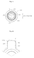
journals 122 of thetripod member 120 has a straight shape orthogonal to an axial line of the joint in vertical cross-section with respect to an axial line of each of thejournals 122. Further, as illustrated inFIG. 11 , each of thejournals 122 has a substantially elliptical shape of being held in contact with theinner roller 134 in a direction orthogonal to the axial line of the joint in lateral cross-section with respect to the axial line of each of thejournals 122, and gaps m are formed between each of thejournals 122 and theinner roller 134 in an axial-linedirectionofthejoint. Theroller units 130 are supported rotatably around thejournals 122 each having such a shape. - In this constant velocity universal joint, the
journals 122 of thetripod member 120 and the roller-guide surfaces 114 of the outerjoint member 110 are engaged with each other into rotational directions of the two shafts through intermediation of theroller units 130. In this way, rotational torque is transmitted at a constant velocity from the driving side to the driven side. Further, when theroller units 130 roll on the roller-guide surfaces 114 while being rotated with respect to thejournals 122, relative axial displacement and angular displacement between theouter joint member 110 and thetripod member 120 are cancelled. - In this case, the
journals 122 are tiltable with respect to theroller units 130 rolling on the roller-guide surfaces 114. Thus, an attempt is made to avoid a state in which theroller units 130 and the roller-guide surfaces 114 are diagonal with respect to each other in accordance with the tilting of thejournals 122 so that induced thrust and sliding resistance are reduced. - [PTL 1]
JP 2000-320563 A - By the way, in manufacture of the above-mentioned conventional tripod type constant velocity universal joint, after the
journals 122 of thetripod member 120 are molded by forging, centering of thejournals 122 is performed. In other words, as illustrated inFIG. 12 , a raw-shaped material 152 corresponding to each of thejournals 122 is forged into a journal shape through plastic flow while being held with adie 160. - In the forging, the entire of a leading end portion of the raw-
shaped material 152 is held with thedie 160, and hence it is difficult to fill an inner-wall corner portion 162 of thedie 160 with the raw-shaped material 152. Thus, a gap P is formed between a leading-end corner portion 152a of the raw-shaped material 152 and an inner-wall corner portion 162 of the die 160. In this way, thejournal 122 is molded under a state in which the leading-end corner portion 152a of the raw-shaped material 152 is not held with thedie 160 at the time of forging. Thus, a leading-end corner portion 122a of thejournal 122 is formed into a gentle curved-surface shape as illustrated by the broken lines inFIG. 13 . - Meanwhile, in a centering step for the
molded journal 122 after forging, at the leading-end corner portion 122a of thejournal 122, it is necessary to form an edge portion as a centering reference, which is brought into contact with a centering jig so as to perform centering. However, with respect to thejournal 122 including the curved-surface-shaped leading-end corner portion 122a formed under the state of not being held with thedie 160 at the time of forging, it is difficult to perform centering by bringing the centering jig into contact with the leading-end corner portion 122a. - Note that, it may be possible to eliminate, at the time of forging of the raw-
shaped material 152, the gap p formed between the inner-wall corner portion 162 of thedie 160 and the leading-end corner portion 152a of the raw-shaped material 152. However, in order to eliminate the gap p, it is necessary to strictly regulate forging conditions such as a size of the raw-shaped material 152 and a setting condition of a forgingmachine. Thus, a forging process becomes more difficult. - Under the circumstance, after forging, a leading end portion of the journal 122 (broken-line part illustrated in
FIG. 13 ) is removed by lathing so that anedge portion 122b as the centering reference is formed at the leading-end corner portion. Note that, when burrs are left around theedge portion 122b even after the lathing process, the burrs are removed by appropriate means such as tumbling or shot-blasting. - In the centering step for the
journal 122, as illustrated inFIG. 14 , theedge portion 122b of thejournal 122 is brought into contact with atapered surface 174 formed around arecessed portion 176 of acentering jig 170 and expanding from a top surface 172 into the axial direction of thejournal 122. In this state, a pressurizing force is applied to the centeringjig 170 from a direction indicated by a hollow arrow D inFIG. 14 . In this way, an axial center α of thejournal 122 is corrected to be orthogonal to an axial line 0 of the joint in the radial direction. Thus, centering of thejournal 122 can be performed. - However, as for the above-mentioned conventional tripod type constant velocity universal j oint, after the molding by forging, the leading end portion of the
journal 122 is required to be removed by lathing for the purpose of forming the centering reference. Thus, it is necessary to perform the lathing step and to form the raw-shaped material 152 to be large in advance in consideration of a lathing amount, which leads to a problem of an increase in weight of the raw-shaped material 152. Further, when burrs are left around theedge portion 122b even after the lathing process, it is also necessary to perform a step of removing the burrs. In this way, man hours increase owing to the lathing step and the burr removing step, which leads to an increase in product cost. - The present invention has been made in view of the above-mentioned problems, and it is therefore an object of the present invention to provide a tripod type constant velocity universal joint and a manufacturing method for the same which contribute to reduction of manufacturing man hours and also to facilitation of the forging process on the journals without involving the increase in weight of the raw-shaped material.
- As a technical measure for achieving the above-mentioned object, the present invention provides a tripod type constant velocity universal joint including: an outer joint member having an inner peripheral surface provided with: three track grooves extending in an axial direction; and roller-guide surfaces extending in the axial direction on both sides of each of the three track grooves; a tripod member including three journals each projected into a radial direction; and a torque transmitting member supported rotatably around each of the three journals of the tripod member and inserted rollably in each of the three track grooves of the outer joint member, and further provides a manufacturing method for the tripod type constant velocity universal joint. The tripod type constant velocity universal joint and the manufacturing method therefor have the following characteristics.
- First, the manufacturing method for a tripod type constant velocity universal joint according to the present invention includes, when forging a raw-shaped material corresponding to each of the three journals into a journal shape with use of a molding surface of a die, under a state in which a relief portion is provided on a raw-shaped-material-leading-end-side of the die, molding an outer peripheral surface of the raw-shaped material into a projected round shape with use of a narrowing surface formed on the molding surface with which the outer peripheral surface of the raw-shaped material is held in contact and a recessed round surface formed between the molding surface and the narrowing surface. Further, in the tripod type constant velocity universal joint according to the present invention, on an outer peripheral surface of each of the three journals, a projected round-corner portion for reducing a lateral sectional area toward a leading end side of each of the three journals is formed.
- In the present invention, when the raw-shaped material corresponding to each of the three journals is forged into the journal shape with use of the molding surface of the die, the relief portion provided on a leading end side of each of the three journals enables plastic flow of the raw-shaped material to be smoothly performed and the raw-shaped material to be reliably held in close contact with the molding surface of the die, the narrowing surface formed on a leading end side of the molding surface, and the recessed round surface formed between the molding surface and the narrowing surface. As a result, the outer peripheral surface of the raw-shaped material is molded in conformity with the molding surface, the recessed round surface, and the narrowing surface of the die, that is, into the projected round shape. In this way, there is obtained a tripod member including journals each having an outer peripheral surface provided with a projected round-corner portion for reducing a lateral sectional area toward the leading end side.
- In this way, the projected round-corner portion formed on the outer peripheral surface of each of the journals can be used as it is as an edge portion as the centering reference in centering after forging. As a result, it is unnecessary to perform conventional lathing and burr removal after forging or to increase a weight of the raw-shaped material in consideration of a lathing amount, and possible to reduce manufacturing man hours. Further, also in the forging step, it is unnecessary to strictly regulate the forging conditions such as the size of the raw-shaped material and the setting condition of the forging machine. Thus, the forging process can be easily performed.
- In addition, a part of the die, which molds the projected round-corner portion to be used as the edge portion as the centering reference, in other words, a part between the molding surface and the narrowing surface of the die is formed as the recessed round surface. Thus, in comparison with a case where the part between the molding surface and the narrowing surface is formed at a right angle, at the time of forging, early abrasion of the die owing to plastic flow of the raw-shaped material at this part can be suppressed. As a result, a life of the die can be prolonged.
- In the manufacturing method for a tripod type constant velocity universal joint according to the present invention, it is desired that the molding surface of the die be a surface parallel to an axial direction of each of the three journals, and the narrowing surface of the die be a tapered surface inclined with respect to the axial direction of each of the three journals. Further, it is desired that, on the outer peripheral surface of each of the three journals in the tripod type constant velocity universal joint according to the present invention, a tapered surface inclined with respect to an axial direction of each of the three journals be formed on a leading end side relative to the projected round-corner portion. With this, at the time of forging, plastic flow of the raw-shaped material can be smoothly performed, with the result that the raw-shaped material is more easily held in close contact with the tapered surface.
- In the manufacturing method for a tripod type constant velocity universal joint according to the present invention, the recessed round surface is only required to be provided at one point in a circumferential direction of the molding surface of the die. Further, it is desired that the projected round-corner portion in the tripod type constant velocity universal joint according to the present invention is provided at one point in a circumferential direction of the outer peripheral surface of each of the three journals. With this, at the time of centering of each of the three journals, when the projected round-corner portion formed with use of the recessed round surface of the die is brought into contact with a centering jig, centering is performed only at the one point in the circumferential direction of the outer peripheral surface of each of the three journals. Thus, centering can be easily performed.
- In the manufacturing method for a tripod type constant velocity universal joint according to the present invention, it is desired that two recessed round surfaces are provided at two points facing each other in a circumferential direction of the molding surface of the die. Further, it is desired that two projected round-corner portions in the tripod type constant velocity universal joint according to the present invention are provided at two points facing each other in the circumferential direction of the outer peripheral surface of each of the three journals. With this, at the time of centering of each of the three journals, when the two projected round-corner portions formed with use of the two recessed round surfaces of the die are brought into contact with a centering jig, centering is performed at the two points in the circumferential direction of the outer peripheral surface of each of the three journals. Thus, centering can be performed with higher accuracy.
- The manufacturing method for a tripod type constant velocity universal joint according to the present invention is desired to further include molding a leading end side of the projected round-corner portion of the raw-shaped material into a recessed round-corner portion with use of a projected round surface formed between the narrowing surface and a relief surface of the relief portion. Further, it is desired that, on the outer peripheral surface of each of the three journals in the tripod type constant velocity universal joint according to the present invention, a recessed round-corner portion be formed on the leading end side relative to the projected round-corner portion. With this, in comparison with a case where the part between the narrowing surface and the relief surface of the relief portion of the die is formed at a right angle, at the time of forging, early abrasion of the die owing to plastic flow of the raw-shapedmaterial at this part can be suppressed. As a result, the life of the die can be prolonged.
- Note that, the present invention is desired to be applied to a tripod type constant velocity universal joint, in which: the torque transmitting member includes: an outer roller inserted in corresponding one of the three track grooves of the outer joint member; and an inner roller externally fitted to corresponding one of the three journals and arranged on an inner peripheral side of the outer roller; an inner peripheral surface of the inner roller has a convex circular-arc shape; each of the three journals has a straight shape orthogonal to an axial line of the tripod type constant velocity universal joint in vertical cross-section, and is held in contact with the inner peripheral surface of the inner roller in a direction orthogonal to the axial line of the tripod type constant velocity universal joint in lateral cross-section; and a gap is formed between each of the three journals and the inner peripheral surface of the inner roller in an axial-line direction of the tripod type constant velocity universal joint. That is, the present invention is desired to be applied to a tripod type constant velocity universal joint of what is called a double-roller type. Note that, in addition to the double-roller type, the present invention is applicable also to tripod type constant velocity universal joints of other types such as a single roller type.
- In the manufacturing method for a tripod type constant velocity universal joint according to the present invention, it is desired that a lateral cross-section of the molding surface of the die have a substantially elliptical shape, and the recessed round surface be arranged on an elliptical longitudinal side. Further, it is desired that a lateral cross-section of each of the three journals in the tripod type constant velocity universal joint according to the present invention have a substantially elliptical shape, and the projected round-corner portion of each of the three journals be arranged on an elliptical longitudinal side. With this, at the time of centering of each of the three journals, when the projected round-corner portion arranged on the elliptical longitudinal side is brought into contact with the centering jig, a contact state of the centering jig with respect to each of the three journals can be stabilized. As a result, centering can be performed with higher accuracy.
- In the present invention, when the raw-shaped material corresponding to each of the three journals is forged into the journal shape with use of the molding surface of the die, the relief portion provided on the leading end side of each of the three journals enables plastic flow of the raw-shaped material to be smoothly performed and the raw-shaped material to be reliably held in close contact with the molding surface of the die, the narrowing surface formed on the leading end side of the molding surface, and the recessed round surface formed between the molding surface and the narrowing surface. As a result, the outer peripheral surface of the raw-shaped material is molded in conformity with the molding surface, the recessed round surface, and the narrowing surface of the die, that is, into the projected round shape. In this way, there is obtained a tripod member including journals each having an outer peripheral surface provided with the projected round-corner portion for reducing a lateral sectional area toward the leading end side.
- In this way, the projected round-corner portion formed on the outer peripheral surface of each of the journals can be used as it is as the edge portion as the centering reference in centering after forging. As a result, it is unnecessary to perform conventional lathing and burr removal after forging or to increase a weight of the raw-shaped material in consideration of a lathing amount, and possible to reduce manufacturing man hours. Further, also in the forging step, it is unnecessary to strictly regulate the forging conditions such as the size of the raw-shapedmaterial and the setting condition of the forging machine. Thus, the forging process can be easily performed.
- In addition, the part of the die, which molds the projected round-corner portion to be used as the edge portion as the centering reference, in other words, the part between the molding surface and the narrowing surface of the die is formed as the recessed roundsurface. Thus, in comparison with a case where the part between the molding surface and the narrowing surface is formed at a right angle, at the time of forging, early abrasion of the die owing to plastic flow of the raw-shapedmaterial at this part can be suppressed. As a result, the life of the die can be prolonged.
-
- [
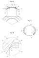
FIG. 1A ] A sectional view of a die under a state of holding a raw-shaped material, illustrating a forging step for a journal according to an embodiment of the present invention. - [
FIG. 1B ] An enlarged view of the portion X ofFIG. 1A , illustrating the forging step for the journal according to the embodiment of the present invention. - [
FIG. 1C ] A sectional view in which the die ofFIG. 1A is viewed from above, illustrating the forging step for the journal according to the embodiment of the present invention. - [
FIG. 2A ] A sectional view of a centering jig under a state of being held in contact with the journal, illustrating a centering step for the journal according to the embodiment of the present invention. - [
FIG. 2B ] An enlarged view of the portion Y ofFIG. 2A , illustrating the centering step for the journal according to the embodiment of the present invention. - [
FIG. 2C ] A plan view in which the journal ofFIG. 2A is viewed from above, illustrating the centering step for the journal according to the embodiment of the present invention. - [
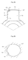
FIG. 3A ] A sectional view of a die under a state of holding the raw-shaped material, illustrating a forging step for a journal according to another embodiment of the present invention. - [
FIG. 3B ] A sectional view in which the die ofFIG. 3A is viewed from above, illustrating the forging step for the journal according to the another embodiment of the present invention. - [
FIG. 4A ] A sectional view of a centering jig under a state of being held in contact with the journal, illustrating a centering forging step for the journal according to the another embodiment of the present invention. - [
FIG. 4B ] A plan view in which the journal ofFIG. 4A is viewed from above, illustrating the centering forging step for the journal according to the another embodiment of the present invention. - [
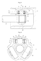
FIG. 5 ] A vertical sectional view illustrating the entire structure of a tripod type constant velocity universal joint according to the embodiments of the present invention. - [
FIG. 6 ] A lateral sectional view ofFIG. 5 . - [
FIG. 7 ] A sectional view of the journal and the roller unit illustrated inFIGS. 5 and 6 . - [
FIG. 8 ] A vertical sectional view illustrating a state in which the tripod type constant velocity universal joint ofFIG. 5 forms an operating angle. - [
FIG. 9 ] A vertical sectional view illustrating the entire structure of a conventional tripod type constant velocity universal joint. - [
FIG. 10 ] A lateral sectional view ofFIG. 9 . - [
FIG. 11 ] A lateral sectional view of the roller unit illustrated inFIG. 10 . - [
FIG. 12 ] A sectional view of a die under a state of holding a raw-shaped material, illustrating a forging step for a journal in a manufacturing method for the conventional tripod type constant velocity universal joint. - [
FIG. 13 ] A partial front view of the journal of a tripod member, illustrating a lathing step for the journal in the manufacturing method for the conventional tripod type constant velocity universal joint. - [
FIG. 14 ] A sectional view of a centering jig under a state of being held in contact with the journal, illustrating the forging step for the journal in the manufacturing method for the conventional tripod type constant velocity universal joint. - Detailed description is made of embodiments of the present invention below. Note that, each of the embodiments below exemplifies a tripod type constant velocity universal joint of a double-roller type, which is capable of reducing vibration at the time of operation. In addition to the double-rollertype, the present invention is applicable also to tripod type constant velocity universal joints of other types such as a single roller type.
- A tripod type constant velocity universal joint according to an embodiment illustrated in
FIGS. 5 and 6 includes a main portion formed of an outerjoint member 10, atripod member 20, androller units 30 as torque transmitting members. One of two shafts on a driving side and a driven side is coupled to the outerjoint member 10, and another of the two shafts is coupled to thetripod member 20. - The outer
joint member 10 is formed into a cup-like shape open at one end, and has an inner peripheral surface equiangularly provided with threelinear track grooves 12 extending in an axial direction and roller-guide surfaces 14 extending in the axial direction on both sides of each of thetrack grooves 12. The outerjoint member 10 incorporates thetripod member 20 and theroller units 30. Thetripod member 20 includes threejournals 22 each projected into a radial direction, and ashaft 40 is press-fitted into acenter hole 28 of thetripod member 20 and spline-fitted thereto. Anannular snap ring 42 prevents theshaft 40 from dropping off with respect to thetripod member 20. - Further, each of the
roller units 30 includes a main portion formed of anouter roller 32, aninner roller 34 arranged on an inside of theouter roller 32 and externally fitted to corresponding one of thejournals 22, andneedle rollers 36 interposed between theouter roller 32 and theinner roller 34. Theroller units 30 are accommodated in thetrack grooves 12 of the outerjoint member 10. Note that, an inner peripheral surface of theinner roller 34 has a convex circular-arc shape. A plurality ofneedle rollers 36 are arranged between theinner roller 34 and theouter roller 32 under what is called a single-row full roller state free from a cage. Theinner roller 34 and theneedle rollers 36 are retained by ring-like washers outer roller 32, thewashers grooves outer roller 32. - Meanwhile, each of the
journals 22 of thetripod member 20 has a straight shape orthogonal to an axial line of the joint in vertical cross-section with respect to an axial line of each of thejournals 22. Further, as illustrated inFIG. 7 , each of thejournals 22 has an elliptical shape of being held in contact with theinner roller 34 in a direction orthogonal to the axial line of the joint in lateral cross-section with respect to the axial line of each of thejournals 22, and gaps n are formed between each of thejournals 22 and theinner roller 34 in an axial-line direction of the joint. Theroller units 30 are supported rotatably around thejournals 22 each having such a shape. - In this constant velocity universal joint, the
journals 22 of thetripod member 20 and the roller-guide surfaces 14 of the outerjoint member 10 are engaged with each other into rotational directions of the two shafts through intermediation of theroller units 30. In this way, rotational torque is transmitted at a constant velocity from the driving side to the driven side. Further, when theroller units 30 roll on the roller-guide surfaces 14 while being rotated with respect to thejournals 22, relative axial displacement and angular displacement between the outerjoint member 10 and thetripod member 20 are cancelled. - In this case, the gaps n are formed between each of the
journals 22 and theinner roller 34 in the axial-line direction of the joint, and thejournals 22 are tiltable with respect to theroller units 30 rolling on the roller-guide surfaces 14. Therefore, even when the joint forms an operating angle, as illustrated inFIG. 8 , theroller unit 30 does not tilt with respect to the roller-guide surfaces 14. Thus, an attempt is made to avoid a state in which theroller units 30 and the roller-guide surfaces 14 are diagonal with respect to each other in accordance with the tilting of thejournals 22 so that induced thrust and sliding resistance are reduced. - The
tripod member 20 in the constant velocity universal joint according to this embodiment is manufactured by performing centering of thejournals 22 after thejournals 22 are molded by forging. In other words, as illustrated inFIG. 1A , thetripod member 20 is forged into a journal shape through plastic flow, with an outerperipheral surface 54 of a raw-shapedmaterial 52 of thejournal 22, which corresponds to a part of a raw-shaped material of thetripod member 20, being held with adie 60. - The
die 60 for holding the outerperipheral surface 54 of the raw-shapedmaterial 52 of thejournal 22 is provided with, as illustrated inFIGS. 1A and 1B , arelief portion 62 formed on a leading end side of the raw-shapedmaterial 52, and has amolding surface 64 parallel to an axial direction of thejournal 22, taperedsurfaces 66 as narrowing surfaces formed on a leading end side of themolding surface 64 and inclined with respect to the axial direction of thejournal 22, andrelief surfaces 68 of therelief portion 62 formed on a leading end side of the tapered surfaces 66 and parallel to the axial direction of thejournal 22. In addition, recessed round surfaces 61 are formed between themolding surface 64 and the tapered surfaces 66, and projected round surfaces 63 are formed between thetapered surfaces 66 and the relief surfaces 68. The recessed round surfaces 61, the tapered surfaces 66, and the projected round surfaces 63 are formed at two points facing each other in a circumferential direction of themolding surface 64 of the die 60 as illustrated inFIG. 1C , in other words, two points on an elliptical longitudinal side to be held in contact with an inner peripheral surface of theinner roller 34 after molding. - At the time of forging the
journal 22, therelief portion 62 provided on a leading end side of thejournal 22 enables plastic flow of the raw-shapedmaterial 52 to be smoothly performed and the raw-shapedmaterial 52 to be reliably held in close contact with themolding surface 64, the recessed round surfaces 61, the tapered surfaces 66, the projected round surfaces 63, and the relief surfaces 68 of thedie 60. As a result, the outerperipheral surface 54 of the raw-shapedmaterial 52 is molded in conformity with themolding surface 64, the recessed round surfaces 61, the tapered surfaces 66, the projected round surfaces 63, and the relief surfaces 68 of thedie 60. - As a result of provision of the
relief portion 62 with respect to the die 60 so as to avoid holding of a leading end portion of the raw-shapedmaterial 52, thedie 60 has the reduced number of points for holding the raw-shapedmaterial 52 in comparison with that in conventional dies. Thus, load on the die 60 can be reduced, and hence a life of the die 60 can be prolonged. In addition, at the time of forging of the raw-shapedmaterial 52, unlike in the conventional dies, it is unnecessary to strictly regulate forging conditions such as a size of the raw-shaped material and a setting condition of a forging machine in order to eliminate gaps p formed between an inner-wall corner portion 162 of adie 160 and a leading-end corner portion 152a of a raw-shaped material 152 (refer toFIG. 12 ). Thus, the raw-shaped material can be more easily forged. - As a result of forging for molding the outer
peripheral surface 54 of the raw-shapedmaterial 52 in conformity with themolding surface 64, the recessed round surfaces 61, the tapered surfaces 66, the projected round surfaces 63, and the relief surfaces 68 of the die 60, as illustrated inFIGS. 2A to 2C , on an outerperipheral surface 24 of thejournal 22, there are formed projected round-corner portions 21 for reducing a lateral sectional area toward the leading end side, taperedstraight portions 26 extending onto a leading end side of the projected round-corner portions 21, and recessed round-corner portions 23 positioned on a leading end side of thestraight portions 26. - After the
journal 22 is molded by forging in this way, thejournal 22 undergoes centering. A centeringjig 70 as illustrated inFIGS. 2A and 2B is used in a centering step for thejournal 22. The centeringjig 70 includes a recessedportion 76 formed of a flattop surface 72 and atapered surface 74 expanding from thetop surface 72 into the axial direction of thejournal 22. Centering of thejournal 22 is performed as follows: as illustrated inFIGS. 2A and 2B , the projected round-corner portions 21 of thejournal 22 are brought into contact with the taperedsurface 74 of the centeringjig 70, and then a pressurizing force is applied to the centeringjig 70 from a direction indicated by a hollow arrow inFIG. 2A . - The projected round-
corner portions 21 of thejournal 22 are parts molded by forging of the raw-shapedmaterial 52 as described above under the state of being held in close contact with the recessed round surfaces 61 of the die 60, and hence each capable of serving as an edge portion as a centering reference at the time of the centering. When the projected round-corner portions 21, each of which is the edge portion as the centering reference, are brought into contact with the taperedsurface 74 of the centeringjig 70, the projected round-corner portions 21 of thejournal 22 can be stably held into contact with the taperedsurface 74 of the centeringjig 70. As a result, centering of thejournal 22 can be reliably performed. - At the time of the centering of the
journal 22, the projected round-corner portions 21 of thejournal 22 are brought into contact with the centeringjig 70. In this context, as illustrated inFIG. 2C , the projected round-corner portions 21 are provided at the two points on the elliptical longitudinal side, and hence a contact state of the centeringjig 70 with respect to thejournal 22 can be stabilized. As a result, centering can be performed with higher accuracy. - As described above, when the
journal 22 is forged with use of the die 60 provided with therelief portion 62 on a leading end side in such a manner that the projected round-corner portions 21 are formed on the outerperipheral surface 24 of thejournal 22, the projected round-corner portions 21 of thejournal 22 can be used as they are as the edge portions as the centering references in centering after forging. As a result, after forging, it is unnecessary to perform a conventional lathing step and a burr removing step which are performed for lathing a leading end portion and removing burrs of the same so as to form the centering reference. Thus, it is unnecessary to form the raw-shapedmaterial 52 to be large in advance in consideration of a lathing amount. As a result, manufacturing man hours can be reduced without an increase in weight of the raw-shapedmaterial 52, and manufacturing cost can be easily reduced. - Further, parts of the die, which mold the projected round-
corner portions 21 to be used as the edge portions as the centering references, in other words, parts between themolding surface 64 and thetapered surfaces 66 of the die 60 are formed as the recessed round surfaces 61. In addition, parts of the die, whichmold the recessed round-corner portions 23 formed on the leading end side of the projected round-corner portions 21, in other words, parts between thetapered surfaces 66 and the relief surfaces 68 are formed as the projected round surfaces 63. Thus, in comparison with a case where the parts between themolding surface 64 and thetapered surfaces 66 and the parts between thetapered surfaces 66 and the relief surfaces 68 are formed at right angles, at the time of forging, early abrasion of the die 60 owing to plastic flow of the raw-shapedmaterial 52 at those parts can be suppressed. As a result, the life of the die 60 can be prolonged. - In the above-mentioned embodiment, the recessed round surfaces 61, the tapered surfaces 66, and the projected round surfaces 63 of the die 60 used at the time of forging are formed at the two points facing each other in the circumferential direction of the
molding surface 64 of the die 60, in other words, the two points on the elliptical longitudinal side to be held in contact with the inner peripheral surface of theinner roller 34 after molding. After the forging, when centering is performed at the two points in the circumferential direction of the outerperipheral surface 24 of thejournal 22, centering can be performed with higher accuracy. Note that, the projected round-corner portions 21 of thejournal 22 are not necessarily provided at the two points facing each other in the circumferential direction, and may be provided over the entire periphery of the outerperipheral surface 24 of thejournal 22. As long as centering with use of the centeringjig 70 is possible, the recessed round surfaces 61, the tapered surfaces 66, and the projected round surfaces 63 of the die 60, in other words, the projected round-corner portions 21, the tapered surfaces 26, and the recessed round-corner portions 23 of thejournal 22 are not particularly limited in position, size, shape, or the like. - For example, as illustrated in
FIGS. 3A and 3B , the recessedround surface 61, the taperedsurface 66, and the projectedround surface 63 may be formed at any one of the two points facing each other in the circumferential direction of themolding surface 64 of a die 60', in other words, any one of the two points on the elliptical longitudinal side to be held in contact with the inner peripheral surface of theinner roller 34 after molding. In this way, when the recessedround surface 61, the taperedsurface 66, and the projectedround surface 63 are formed at one point in the circumferential direction of themolding surface 64 of the die 60' , as illustrated inFIGS. 4A and 4B , the projected round-corner portion 21, the taperedsurface 26, and the recessed round-corner portion 23 are formed at one point in the circumferential direction of the outerperipheral surface 24 of thejournal 22. In this case, as illustrated inFIG. 4A , the projected round-corner portion 21 of thejournal 22 is brought into contact with the taperedsurface 74 of a centering jig 70' so that centering can be performed with an elastic force of a spring applied as indicated by a hollow arrow inFIG. 4A . In this way, when centering is performed only at the one point in the circumferential direction of the outerperipheral surface 24 of thejournal 22, centering can be easily performed. - Notethat, in the above-mentioned embodiments, although the projected round-
corner portion 21 and the recessed round-corner portion 23 are connected with the taperedsurface 26, as long as the projected round-corner portion 21 can be formed as the edge portion as the centering reference on the outerperipheral surface 24 of thejournal 22 after forging, the taperedsurface 26 may be omitted and the projected round-corner portion 21 and the recessed round-corner portion 23 may be connected continuously to each other. - The present invention is not limited to the above-mentioned embodiments at all, and as a matter of course, can be carried out in other various modes without departing from the spirit of the present invention. The scope of the present invention is described in the scope of claims, and includes meaning of equivalents of elements described in the scope of claims and all changes in the scope of claims.
Claims (14)
- A manufacturing method for a tripod type constant velocity universal joint comprising:an outer joint member having an inner peripheral surface provided with:three track grooves extending in an axial direction;androller-guide surfaces extending in the axial direction on both sides of each of the three track grooves;a tripod member comprising three journals each projected into a radial direction; anda torque transmitting member supported rotatably around each of the three journals of the tripod member and inserted rollably in each of the three track grooves of the outer joint member,the manufacturing method comprising, when forging a raw-shaped material corresponding to each of the three journals into a journal shape with use of a molding surface of a die, under a state in which a relief portion is provided on a raw-shaped-material-leading-end-side of the die, molding an outer peripheral surface of the raw-shaped material into a projected round shape with use of a narrowing surface formed on the molding surface with which the outer peripheral surface of the raw-shaped material is held in contact and a recessed round surface formed between the molding surface and the narrowing surface.
- A manufacturing method for a tripod type constant velocity universal joint according to claim 1,
wherein the molding surface of the die comprises a surface parallel to an axial direction of each of the three journals, and
wherein the narrowing surface of the die comprises a tapered surface inclined with respect to the axial direction of each of the three journals. - A manufacturing method for a tripod type constant velocity universal joint according to claim 1 or 2, wherein the recessed round surface is provided at one point in a circumferential direction of the molding surface of the die.
- A manufacturing method for a tripod type constant velocity universal joint according to claim 1 or 2, wherein the recessed round surface comprises two recessed round surfaces provided at two points facing each other in a circumferential direction of the molding surface of the die.
- A manufacturing method for a tripod type constant velocity universal joint according to any one of claims 1 to 4, further comprising molding the outer peripheral surface of the raw-shaped material into a recessed round shape with use of a projected round surface formed between the narrowing surface and a relief surface of the relief portion provided on a leading end side of the narrowing surface.
- A manufacturing method for a tripod type constant velocity universal joint according to any one of claims 1 to 5,
wherein the torque transmitting member comprises:an outer roller inserted in corresponding one of the three track grooves of the outer joint member; andan inner roller externally fitted to corresponding one of the three journals and arranged on an inner peripheral side of the outer roller,wherein an inner peripheral surface of the inner roller has a convex circular-arc shape,
wherein each of the three journals has a straight shape orthogonal to an axial line of the tripod type constant velocity universal joint in vertical cross-section, and is held in contact with the inner peripheral surface of the inner roller in a direction orthogonal to the axial line of the tripod type constant velocity universal joint in lateral cross-section, and
wherein a gap is formed between each of the three journals and the inner peripheral surface of the inner roller in an axial-line direction of the tripod type constant velocity universal joint. - A manufacturing method for a tripod type constant velocity universal joint according to any one of claims 1 to 6,
wherein a lateral cross-section of the molding surface of the die has an elliptical shape, and
wherein the recessed round surface is arranged on a substantially-elliptical longitudinal side. - A tripod type constant velocity universal joint, comprising:an outer joint member having an inner peripheral surface provided with:three track grooves extending in an axial direction; androller-guide surfaces extending in the axial direction on both sides of each of the three track grooves;a tripod member comprising three journals each projected into a radial direction; anda torque transmitting member supported rotatably around each of the three journals of the tripod member and inserted rollably in each of the three track grooves of the outer joint member,wherein, on an outer peripheral surface of each of the three journals, a projected round-corner portion for reducing a lateral sectional area toward a leading end side of each of the three journals is formed.
- A tripod type constant velocity universal joint according to claim 8, wherein, on the outer peripheral surface of each of the three journals, a tapered surface inclined with respect to an axial direction of each of the three journals is formed on a leading end side relative to the projected round-corner portion.
- A tripod type constant velocity universal joint according to claim 8 or 9, wherein the projected round-corner portion is provided at one point in a circumferential direction of the outer peripheral surface of each of the three journals.
- A tripod type constant velocity universal joint according to claim 8 or 9, wherein the projected round-corner portion comprises two projected round-corner portions provided at two points facing each other in a circumferential direction of the outer peripheral surface of each of the three journals.
- A tripod type constant velocity universal joint according to any one of claims 8 to 11, wherein, on the outer peripheral surface of each of the three journals, a recessed round-corner portion is formed on the leading end side relative to the projected round-corner portion.
- A tripod type constant velocity universal joint according to any one of claims 8 to 12,
wherein the torque transmitting member comprises:an outer roller inserted in corresponding one of the three track grooves of the outer joint member; andan inner roller externally fitted to corresponding one of the three journals and arranged on an inner peripheral side of the outer roller,wherein an inner peripheral surface of the inner roller has a convex circular-arc shape,
wherein each of the three journals has a straight shape orthogonal to an axial line of the tripod type constant velocity universal joint in vertical cross-section, and is held in contact with the inner peripheral surface of the inner roller in a direction orthogonal to the axial line of the tripod type constant velocity universal joint in lateral cross-section, and
wherein a gap is formed between each of the three journals and the inner peripheral surface of the inner roller in an axial-line direction of the tripod type constant velocity universal joint. - A tripod type constant velocity universal joint according to any one of claims 8 to 13,
wherein a lateral cross-section of each of the three journals has an elliptical shape, and
wherein the projected round-corner portion of each of the three journals is arranged on a substantially-elliptical longitudinal side.
Applications Claiming Priority (2)
| Application Number | Priority Date | Filing Date | Title |
|---|---|---|---|
| JP2009102144A JP5323572B2 (en) | 2009-04-20 | 2009-04-20 | Tripod type constant velocity universal joint and manufacturing method thereof |
| PCT/JP2010/056070 WO2010122893A1 (en) | 2009-04-20 | 2010-04-02 | Tripod constant-velocity universal joint and method for producing the same |
Publications (2)
| Publication Number | Publication Date |
|---|---|
| EP2423525A1 true EP2423525A1 (en) | 2012-02-29 |
| EP2423525A4 EP2423525A4 (en) | 2017-05-10 |
Family
ID=43011015
Family Applications (1)
| Application Number | Title | Priority Date | Filing Date |
|---|---|---|---|
| EP10766952.5A Ceased EP2423525A4 (en) | 2009-04-20 | 2010-04-02 | Tripod constant-velocity universal joint and method for producing the same |
Country Status (5)
| Country | Link |
|---|---|
| US (1) | US8491398B2 (en) |
| EP (1) | EP2423525A4 (en) |
| JP (1) | JP5323572B2 (en) |
| CN (1) | CN102405357B (en) |
| WO (1) | WO2010122893A1 (en) |
Families Citing this family (3)
| Publication number | Priority date | Publication date | Assignee | Title |
|---|---|---|---|---|
| US11073180B2 (en) * | 2017-12-07 | 2021-07-27 | Neapco Intellectual Property Holdings, Llc | Constant velocity joint with cooperating boot and shaft vent channels |
| CN112240354B (en) * | 2019-07-19 | 2021-12-07 | 上海纳铁福传动系统有限公司 | High-strength compact type three-pivot universal joint |
| CN120023282B (en) * | 2025-04-22 | 2025-07-08 | 山西富兴通重型环锻件有限公司 | Large flange forging equipment and forging method |
Family Cites Families (19)
| Publication number | Priority date | Publication date | Assignee | Title |
|---|---|---|---|---|
| FR2250916B3 (en) * | 1973-11-08 | 1977-05-06 | Schmid Leopold | |
| JPH0235052Y2 (en) * | 1985-06-24 | 1990-09-21 | ||
| JPS624624A (en) | 1985-07-01 | 1987-01-10 | Suzuki Motor Co Ltd | Automobile window |
| JPH0719549B2 (en) | 1985-07-17 | 1995-03-06 | ソニー株式会社 | Cathode ray tube |
| JPH0223855Y2 (en) * | 1985-07-19 | 1990-06-29 | ||
| JPS6249022A (en) | 1985-08-26 | 1987-03-03 | Daikin Mfg Co Ltd | Clutch cover assembly |
| JPH0322577Y2 (en) * | 1985-09-17 | 1991-05-16 | ||
| JPH04135032A (en) | 1990-09-27 | 1992-05-08 | Toyota Motor Corp | Manufacture of outer ring of loevro joint |
| GB2268789B (en) * | 1992-07-14 | 1995-05-17 | Loehr & Bromkamp Gmbh | Tripode type constant velocity ratio joints |
| JP3711758B2 (en) | 1998-09-08 | 2005-11-02 | 日本精工株式会社 | Manufacturing method of cylindrical roller for tripod type constant velocity joint |
| JP3599618B2 (en) | 1999-03-05 | 2004-12-08 | Ntn株式会社 | Constant velocity universal joint |
| US6632143B2 (en) * | 2000-03-31 | 2003-10-14 | Ntn Corporation | Constant velocity universal joint |
| JP4064067B2 (en) * | 2001-03-08 | 2008-03-19 | 本田技研工業株式会社 | Constant velocity joint |
| KR100741308B1 (en) * | 2005-12-27 | 2007-07-23 | 한국프랜지공업 주식회사 | Tripod Constant Joint Structure and Assembly Method of Roller Assembly |
| KR100815677B1 (en) * | 2006-05-11 | 2008-03-20 | 위아 주식회사 | Tripod Constant Velocity Joint |
| JP2008025800A (en) * | 2006-07-25 | 2008-02-07 | Ntn Corp | Bipod universal joint |
| JP4869968B2 (en) * | 2007-02-02 | 2012-02-08 | Ntn株式会社 | Closed forging die and forging method |
| DE102008020342A1 (en) | 2008-04-23 | 2009-10-29 | Volkswagen Ag | Tripod joint, has tripod spider with pin having convex circumferential surface, where damper body is inserted between inner ring and pin to provide resistance against tilting of roll elements opposite to pin |
| JP5377908B2 (en) | 2008-08-28 | 2013-12-25 | Ntn株式会社 | Manufacturing method of tripod type constant velocity universal joint |
-
2009
- 2009-04-20 JP JP2009102144A patent/JP5323572B2/en active Active
-
2010
- 2010-04-02 US US13/259,504 patent/US8491398B2/en active Active
- 2010-04-02 EP EP10766952.5A patent/EP2423525A4/en not_active Ceased
- 2010-04-02 CN CN201080017458.8A patent/CN102405357B/en active Active
- 2010-04-02 WO PCT/JP2010/056070 patent/WO2010122893A1/en not_active Ceased
Non-Patent Citations (1)
| Title |
|---|
| See references of WO2010122893A1 * |
Also Published As
| Publication number | Publication date |
|---|---|
| JP2010249294A (en) | 2010-11-04 |
| US8491398B2 (en) | 2013-07-23 |
| CN102405357A (en) | 2012-04-04 |
| US20120021842A1 (en) | 2012-01-26 |
| WO2010122893A1 (en) | 2010-10-28 |
| CN102405357B (en) | 2014-09-17 |
| JP5323572B2 (en) | 2013-10-23 |
| EP2423525A4 (en) | 2017-05-10 |
Similar Documents
| Publication | Publication Date | Title |
|---|---|---|
| JP3859295B2 (en) | Sliding type constant velocity universal joint | |
| EP3168490B1 (en) | Tripod-type constant-velocity universal joint | |
| US8388456B2 (en) | Fixed-type, constant-velocity universal joint | |
| US8342969B2 (en) | Tripod-type constant-velocity universal joint and method of manufacturing the same | |
| US8491398B2 (en) | Tripod type constant-velocity universal joint and method for producing the same | |
| EP1505308B1 (en) | Constant velocity universal joint | |
| JP2011231792A (en) | Sliding constant velocity universal joint, and ironing process method of outer joint member thereof | |
| WO2011078103A1 (en) | Tripod constant-velocity universal joint | |
| US7878914B2 (en) | Constant velocity joint of tripod type | |
| EP2133582B1 (en) | Constant velocity universal joint | |
| KR20170094861A (en) | Cross Groove Constant Velocity Joint | |
| US9631676B2 (en) | Tripod joint having low vibration inducing forces | |
| JP6591223B2 (en) | Fixed constant velocity universal joint | |
| JP5372364B2 (en) | Tripod type constant velocity universal joint | |
| US10626924B2 (en) | Constant velocity universal joint | |
| JP6433689B2 (en) | Sliding constant velocity universal joint | |
| CN120608928A (en) | Sliding constant velocity universal coupling | |
| CN120720340A (en) | Outer coupling member for constant velocity universal joint and fixed constant velocity universal joint equipped with the same | |
| JP2026053014A (en) | Tripod type constant velocity universal joint | |
| JP5154199B2 (en) | Tripod type constant velocity universal joint | |
| CN119278320A (en) | Constant velocity universal coupling and method for manufacturing the same | |
| JP2022148776A (en) | Tripod type constant velocity universal joint | |
| JP2004036690A (en) | Constant velocity universal joint | |
| KR101891135B1 (en) | Tripod constant velocity joint | |
| CN118257792A (en) | Power transmission shaft, drive shaft and outer coupling components |
Legal Events
| Date | Code | Title | Description |
|---|---|---|---|
| PUAI | Public reference made under article 153(3) epc to a published international application that has entered the european phase |
Free format text: ORIGINAL CODE: 0009012 |
|
| 17P | Request for examination filed |
Effective date: 20111118 |
|
| AK | Designated contracting states |
Kind code of ref document: A1 Designated state(s): AT BE BG CH CY CZ DE DK EE ES FI FR GB GR HR HU IE IS IT LI LT LU LV MC MK MT NL NO PL PT RO SE SI SK SM TR |
|
| DAX | Request for extension of the european patent (deleted) | ||
| RA4 | Supplementary search report drawn up and despatched (corrected) |
Effective date: 20170412 |
|
| RIC1 | Information provided on ipc code assigned before grant |
Ipc: F16D 3/20 20060101ALI20170406BHEP Ipc: F16D 3/205 20060101AFI20170406BHEP Ipc: B21K 1/14 20060101ALI20170406BHEP Ipc: B21K 1/76 20060101ALI20170406BHEP |
|
| STAA | Information on the status of an ep patent application or granted ep patent |
Free format text: STATUS: EXAMINATION IS IN PROGRESS |
|
| 17Q | First examination report despatched |
Effective date: 20190328 |
|
| REG | Reference to a national code |
Ref country code: DE Ref legal event code: R003 |
|
| STAA | Information on the status of an ep patent application or granted ep patent |
Free format text: STATUS: THE APPLICATION HAS BEEN REFUSED |
|
| 18R | Application refused |
Effective date: 20221201 |