EP2423516A1 - Pipe securing structure for cylinder tube - Google Patents
Pipe securing structure for cylinder tube Download PDFInfo
- Publication number
- EP2423516A1 EP2423516A1 EP10766950A EP10766950A EP2423516A1 EP 2423516 A1 EP2423516 A1 EP 2423516A1 EP 10766950 A EP10766950 A EP 10766950A EP 10766950 A EP10766950 A EP 10766950A EP 2423516 A1 EP2423516 A1 EP 2423516A1
- Authority
- EP
- European Patent Office
- Prior art keywords
- tab
- bolt
- pipe
- pair
- bracket
- Prior art date
- Legal status (The legal status is an assumption and is not a legal conclusion. Google has not performed a legal analysis and makes no representation as to the accuracy of the status listed.)
- Granted
Links
Images


Classifications
-
- F—MECHANICAL ENGINEERING; LIGHTING; HEATING; WEAPONS; BLASTING
- F15—FLUID-PRESSURE ACTUATORS; HYDRAULICS OR PNEUMATICS IN GENERAL
- F15B—SYSTEMS ACTING BY MEANS OF FLUIDS IN GENERAL; FLUID-PRESSURE ACTUATORS, e.g. SERVOMOTORS; DETAILS OF FLUID-PRESSURE SYSTEMS, NOT OTHERWISE PROVIDED FOR
- F15B15/00—Fluid-actuated devices for displacing a member from one position to another; Gearing associated therewith
- F15B15/08—Characterised by the construction of the motor unit
- F15B15/14—Characterised by the construction of the motor unit of the straight-cylinder type
- F15B15/149—Fluid interconnections, e.g. fluid connectors, passages
-
- F—MECHANICAL ENGINEERING; LIGHTING; HEATING; WEAPONS; BLASTING
- F16—ENGINEERING ELEMENTS AND UNITS; GENERAL MEASURES FOR PRODUCING AND MAINTAINING EFFECTIVE FUNCTIONING OF MACHINES OR INSTALLATIONS; THERMAL INSULATION IN GENERAL
- F16L—PIPES; JOINTS OR FITTINGS FOR PIPES; SUPPORTS FOR PIPES, CABLES OR PROTECTIVE TUBING; MEANS FOR THERMAL INSULATION IN GENERAL
- F16L3/00—Supports for pipes, cables or protective tubing, e.g. hangers, holders, clamps, cleats, clips, brackets
- F16L3/08—Supports for pipes, cables or protective tubing, e.g. hangers, holders, clamps, cleats, clips, brackets substantially surrounding the pipe, cable or protective tubing
- F16L3/10—Supports for pipes, cables or protective tubing, e.g. hangers, holders, clamps, cleats, clips, brackets substantially surrounding the pipe, cable or protective tubing divided, i.e. with two members engaging the pipe, cable or protective tubing
- F16L3/1033—Supports for pipes, cables or protective tubing, e.g. hangers, holders, clamps, cleats, clips, brackets substantially surrounding the pipe, cable or protective tubing divided, i.e. with two members engaging the pipe, cable or protective tubing with two members engaging the pipe, cable or tubing, the two members being joined only on one side of the pipe
- F16L3/1041—Supports for pipes, cables or protective tubing, e.g. hangers, holders, clamps, cleats, clips, brackets substantially surrounding the pipe, cable or protective tubing divided, i.e. with two members engaging the pipe, cable or protective tubing with two members engaging the pipe, cable or tubing, the two members being joined only on one side of the pipe and being adapted to accommodate pipes of various diameters
-
- F—MECHANICAL ENGINEERING; LIGHTING; HEATING; WEAPONS; BLASTING
- F16—ENGINEERING ELEMENTS AND UNITS; GENERAL MEASURES FOR PRODUCING AND MAINTAINING EFFECTIVE FUNCTIONING OF MACHINES OR INSTALLATIONS; THERMAL INSULATION IN GENERAL
- F16L—PIPES; JOINTS OR FITTINGS FOR PIPES; SUPPORTS FOR PIPES, CABLES OR PROTECTIVE TUBING; MEANS FOR THERMAL INSULATION IN GENERAL
- F16L3/00—Supports for pipes, cables or protective tubing, e.g. hangers, holders, clamps, cleats, clips, brackets
- F16L3/22—Supports for pipes, cables or protective tubing, e.g. hangers, holders, clamps, cleats, clips, brackets specially adapted for supporting a number of parallel pipes at intervals
- F16L3/237—Supports for pipes, cables or protective tubing, e.g. hangers, holders, clamps, cleats, clips, brackets specially adapted for supporting a number of parallel pipes at intervals for two pipes
Definitions
- This invention relates to a structure for fixing a working fluid pipe in the vicinity of an outer periphery of a cylinder tube such as a fluid pressure cylinder.
- a working fluid pipe is fixed to a side face of a cylinder tube, for example.
- the pipe is preferably disposed in close contact with the cylinder tube.
- JP2008-057606A published by the Japan Patent Office in 2008, proposes a fixing structure for fixing this type of pipe to a cylinder tube.
- the pipe fixing structure proposed in the prior art includes a pair of bands fastened to the cylinder tube, and a sheet metal bracket welded to one of the bands.
- a block-shaped clamp is fixed to the bracket by a bolt and a nut.
- the pipe is sandwiched between the clamp and the bracket.
- a diameter of the clamp must be increased when the diameter of the pipe is increased.
- increases occur in the size and weight of the pipe structure including the clamp and the bracket.
- a thickness of the band must be increased to ensure that the band is not broken by an external force such as vibration. This also leads to an increase in the weight of the pipe structure.
- this invention provides a pipe fixing structure that supports a pipe on a cylinder tube, comprising a band fastened to an outer periphery of the cylinder tube, the band comprising a first tab that projects outward in a radial direction and a second tab that projects outward in the radial direction, and a bracket that supports the pipe, wherein the bracket is formed with an inverted U-shaped cross-section constituted by a pair of leg plate portions and a top plate portion formed integrally with the leg plate portions to join the leg plate portions, and the pair of leg plate portions are fixed to the first tab and the second tab by a bolt.
- This invention also provides a fluid pressure cylinder that supports a pipe on a cylinder tube, comprising a band fastened to an outer periphery of the cylinder tube, the band comprising a first tab that projects outward in a radial direction and a second tab that projects outward in the radial direction, and a bracket that supports the pipe, wherein the bracket is formed with an inverted U-shaped cross-section constituted by a pair of leg plate portions and a top plate portion formed integrally with the leg plate portions to join the leg plate portions, and the pair of leg plate portions are fixed to the first tab and the second tab by a bolt.
- a fluid pressure cylinder 1 that drives a boom or the like of a working machine is formed inside a cylinder tube 2 and activated by a working fluid pressure supplied through a pipe 4.
- Working oil for example, is used as the working fluid.
- a water-soluble replacement liquid or air may be used.
- the pipe 4 is fixed to an outer periphery of the cylinder tube 2 using a pipe fixing structure according to this invention.
- the pipe fixing structure includes a pair of bands 10 wrapped fixedly around an outer peripheral surface 2a of the cylinder tube 2, a bracket 20 fixed to the band 10, and a clamp 40 that grips the pipe 4 in combination with the bracket 20. As shown in the figure, the pipe 4 is supported parallel to the cylinder tube 2 via the pipe fixing structure.
- the band 10 is formed from sheet metal.
- the band 10 is constituted by a band plate-shaped main body portion 10b fixed to the outer peripheral surface 2a of the cylinder tube 2, a first pair of tabs 11a that project radially outward from either axial end of the main body portion 10b fixed to the outer peripheral surface 2a of the cylinder tube 2, and a similar second pair of tabs 11b provided at an angular interval ⁇ from the first pair of tabs 11a.
- the main body portion 10b is formed with an arc-shaped cross-section of substantially 180 degrees in order to cover substantially half of the circumference of the cylinder tube 2.
- a joining portion 10a bent in a radial direction is formed on either circumferential direction end of the main body portion 10b.
- a joining hole 10c is formed in each joining portion 10a.
- the band 10 is fixed to the cylinder tube 2 as follows.
- the two bands 10 are wrapped around the cylinder tube 2 such that the joining portions 10a of one band 10 oppose the joining portions 10a of the other band 10, whereupon tip ends of bolts 5 inserted into the joining holes 10c formed in the opposing joining portions 10a are screwed to nuts 6.
- the nuts 6 are fixed to one of the joining portions 10a of each band 10 in advance by welding.
- a cross-section of the main body portion 10b of the band 10 forms an arc having a curvature radius of substantially D/2.
- the main body portion 10b , the joining portions 10a, the first pair of tabs 11a, and the second pair of tabs 11b are formed integrally in advance by press-molding sheet metal cut into predetermined shapes.
- a band having a curvature radius R that is 1/2 the outer diameter D of the cylinder tube 2 is used.
- Fixing holes 12 for fixing the bracket 20 are formed coaxially in the first pair of tabs 11a and the second pair of tabs 11b, respectively.
- the fixing holes 12 are preferably formed as elongated holes extending in a radial direction so that minute adjustments can be made to relative positions of the band 10 and the bracket 20.
- the bracket 20 is constituted by a pair of leg plate portions 20a, and a top plate portion 20b formed integrally with the leg plate portions 20a to join the leg plate portions 20a.
- the bracket 20 thus formed has an inverted U-shaped cross-section.
- the top plate portion 20b is formed to be flat, but the top plate portion 20b may be formed with an arched cross-section.
- the leg plate portion 20a is formed with a first bolt hole 22 having a circular cross-section and a second bolt hole 23 having an elliptical cross-section.
- the second bolt hole 23 having the elliptical cross-section is formed along a bolt hole base line G linking a center of the first bolt hole 22 to a center of the second bolt hole 23. More precisely, the second bolt hole 23 is formed such that a long axis of the elliptical cross-section is positioned on the bolt hole base line G.
- Two first bolt holes 22 and two second bolt holes 23 are respectively positioned coaxially in the bracket 20.
- a transverse direction dimension of the bracket 20 is set such that respective inner surfaces of the two leg plate portions 20a fit onto respective outer surfaces of the first pair of tabs 11a and second pair of tabs 11b.
- a bolt 7 penetrates the two first bolt holes 22 in the two leg plate portions 20a of the bracket 20 and the two fixing holes 12 of the first pair of tabs 11 a positioned on the inside thereof, and a nut 17 is fastened to a penetrating end of the bolt 7.
- a bolt 8 penetrates the two second bolt holes 23 in the two leg plate portions 20a and the two fixing holes 12 of the second pair of tabs 11b positioned on the inside thereof, and a nut 18 is fastened to a penetrating end of the bolt 8.
- the bracket 20 is fixed to the band 10.
- a notch 20d for receiving the pipe 4 is formed in the bracket 20.
- the notch 20d has an arc-shaped cross-section that is oriented radially outward when seen from a direction of a central axis 02 of the cylinder tube 2 in a state where the bracket 20 is fixed to the cylinder tube 2 via the band 10.
- the bracket 20 is formed integrally by press-molding sheet metal cut in advance into a predetermined shape including the notch 20d.
- the clamp 40 is constituted by a flat plate-shaped base portion 40a fixed to the top plate portion 20b by a bolt 9 and a nut 19, and a tip end portion 40b formed integrally with one end of the base portion 40a.
- a hole 20e for fixing the base portion 40a is formed in the top plate portion 20b of the bracket 20.
- the nut 19 is fixed to a periphery of the hole 20e in advance by welding.
- the tip end portion 40b is formed with an arc-shaped cross-section that corresponds to the notch 20d formed in the bracket 20.
- the clamp 40 is formed by press-molding sheet metal cut in advance into a predetermined shape.
- the base portion 40a of the clamp 40 is fixed to the top plate portion 20b by the bolt 9 and the nut 19 while the pipe 4 is seated on the notch 20d.
- the pipe 4 is sandwiched between the bracket 20 and the clamp 40 supported on the bracket 20 in cantilever fashion, and therefore the pipe 4 is prevented from falling out of the notch 20d.
- the arc-shaped cross-section of the notch 20d in the bracket 20 and the arc-shaped cross-section of the tip end portion 40b of the clamp 40 are both set with a radius R.
- the pipe fixing structure has been designed with the aim of supporting a pipe 4A having the radius R, a pipe 4B having a smaller diameter than the pipe 4A, or a pipe 4C having an even smaller diameter.
- the radius R is set to be equal to a maximum pipe diameter that can be supported by the bracket 20.
- a clamp 40 having a smaller radius R on the arc-shaped cross-section of the tip end portion 40b is used.
- a plurality of pipes 4 having difference radii R can be accommodated by replacing the clamp 40 alone, i.e. without replacing the bracket 20.
- the clamp 40 is formed by a spring material that is capable of elastic deformation in the radial direction of the figure, pipes 4 of different diameters can be held in the notch 20d using the same clamp 40.
- the clamp 40 is preferably formed with a cantilever structure in which the base portion 40a is fixed so that the clamp 40 is capable of elastic deformation in the radial direction of the clamp 40.
- an angle ⁇ is formed by a straight line F1 linking the central axis 02 of the cylinder tube 2 to a center 07 of the fixing holes 12 in the first pair of tabs 11a and a straight line F2 linking the central axis 02 of the cylinder tube 2 to a center 08 of the fixing holes 12 in the second pair of tabs 11b.
- the angle ⁇ corresponds to the aforementioned angular interval between the first pair of tabs 11a and the second pair of tabs 11b.
- bands 10 having different diameters are used in accordance with variation in the outer diameter D of the cylinder tube 2.
- bracket 20 is used in relation to bands 10 having different diameters.
- the second bolt 8 penetrates the center of the elliptical second bolt hole 23.
- the outer diameter D of the cylinder tube 2 at this time is set as a standard diameter.
- a band 10 having a correspondingly larger diameter is used.
- the position in which the second bolt 8 penetrates the second bolt hole 23 is displaced from the center of the second bolt hole 23 in a direction heading away from the first bolt hole 22.
- the outer diameter D of the cylinder tube 2 is smaller than the standard diameter
- a band 10 having a correspondingly smaller diameter is used. In this case, the position in which the second bolt 8 penetrates the second bolt hole 23 is displaced from the center of the second bolt hole 23 in a direction approaching the first bolt hole 22.
- bands 10 having different diameters are used in accordance with differences in the outer diameter D of the cylinder tube 2. Regardless of the diameter of the band 10, formation positions of the first tabs 11a and second tabs 11b are set in advance such that the angle ⁇ between the straight lines F1 and F2 remains constant.
- an angle ⁇ formed by a straight line E that passes through the center 07 of the first bolt 7 orthogonally to the straight line F1 and the aforesaid bolt hole base line G is set to be 1/2 the angle ⁇ formed by the straight lines F1 and F2.
- a distance from the central axis 02 of the cylinder tube 2 to the center 07 of the first bolt 7 is set to be equal to a distance from the central axis 02 of the cylinder tube 2 to the center 08 of the second bolt 8.
- This distance is set as L.
- the distance H is set in advance such that the pipe 4 does not interfere with the cylinder tube 2.
- the distance H remains constant regardless of the diameter of the band 10.
- a distance X between the center 07 of the first bolt 7 and the center 08 of the second bolt 8 along the straight line F1 is expressed by a following equation.
- X L ⁇ 1 - cos ⁇
- a distance Y between the center 07 of the first bolt 7 and the center 08 of the second bolt 8 along the straight line E, which is orthogonal to the straight line F1, is expressed by a following equation.
- Y L ⁇ sin ⁇
- a length P of the second bolt hole 23 is therefore set in accordance with a maximum value and a minimum value of the distance Z.
- the first tabs 11a and second tabs 11b are disposed such that the angle ⁇ and the distance H are respectively maintained at constant values in relation to bands 10 of different diameters, while the second bolt hole 23 in the bracket 20 is formed as an elongated hole extending along the bolt hole base line G.
- the bracket 20 fixed to the bands 10 of various diameters maintains the angle ⁇ and the distance H shown in FIG. 5A relative to the band 10 at all times. Therefore, even when the pipe 4 is fixed to a cylinder tube 2 having a different outer diameter D, the distance and position relationship between the cylinder tube 2 and the pipe 4 can be kept constant at all times using the same bracket 20.
- the second bolt hole 23 may be formed as a rounded hole rather than an elongated hole and the first bolt hole 22 may be formed as an elongated hole extending along the bolt hole base line G.
- the band 10, the bracket 20, and the clamp 40 are respectively formed by press-molding sheet metal cut into predetermined shapes, and therefore the constitutional components of the pipe fixing structure can be manufactured easily and at a low weight.
- the bracket 20 is formed with an inverted U-shaped cross-section constituted by the two leg plate portions 20a fixed to the tabs 11a 11b and the leg plate portion 20a joining the leg plate portions 20a, and therefore the pipe 4 can be supported with a high degree of rigidity.
- the bracket 20 supports the single pipe 4, but the bracket 20 may support a plurality of pipes.
- the bracket 20 is fixed to the band 10 by screwing the nut 17 (18) to the bolt 7 (8) that penetrates the pair of tabs 11a (11b) and the two leg plate portions 20a of the bracket 20.
- the bracket 20 may be fixed to the band 10 using a total of four bolts and four nuts by joining one of the tabs 11a (11b) and one of the leg plate portions 20a with a bolt and a nut.
- each leg plate portion 20a is fixed to each tab 11a (11b) individually, and therefore a further improvement in support rigidity can be achieved in relation to a collapsing direction of the leg plate portions 20a.
- the structure for fixing the bracket 20 to the band 10 is not limited to a fixing structure using a bolt and a nut.
- the base portion 40a of the clamp 40 is supported on the top plate portion 20b by a cantilever structure fixed by the bolt 9 and the nut 19.
- a separate base portion may be provided on a tip end of the tip end portion 40b on the opposite side of the clamp 40 to the base portion 40a, and the two base portions may be fixed to the bracket 20 individually by bolts.
- Five pairs of tabs 11a-11e are formed at equal angular intervals ⁇ around the outer periphery of the main body portion 10b of the band 10 according to this embodiment.
- the number of options relating to the position in which the bracket 20 is attached to the band 10 in the circumferential direction can be increased.
- two brackets 20 can be fixed to a single band 10.
- Tokugan 2009-104887 and Tokugan 2009-104889 are hereby incorporated by reference.
- this invention is applied to a fluid pressure cylinder for a working machine, but the scope of application of this invention is not limited thereto.
Landscapes
- Engineering & Computer Science (AREA)
- General Engineering & Computer Science (AREA)
- Mechanical Engineering (AREA)
- Physics & Mathematics (AREA)
- Fluid Mechanics (AREA)
- Clamps And Clips (AREA)
Abstract
Description
- This invention relates to a structure for fixing a working fluid pipe in the vicinity of an outer periphery of a cylinder tube such as a fluid pressure cylinder.
- In a fluid pressure cylinder that drives a boom of a working machine, a working fluid pipe is fixed to a side face of a cylinder tube, for example. To prevent the pipe from vibrating, prevent looseness in a pipe connecting portion, and increase the compactness of a disposal space including the cylinder tube, the pipe is preferably disposed in close contact with the cylinder tube.
-
JP2008-057606A - The pipe fixing structure proposed in the prior art includes a pair of bands fastened to the cylinder tube, and a sheet metal bracket welded to one of the bands. A block-shaped clamp is fixed to the bracket by a bolt and a nut. The pipe is sandwiched between the clamp and the bracket.
- In this pipe structure, every time an attachment position for attaching the pipe to the cylinder tube and an outer diameter of the cylinder tube are modified, component dimensions and a welding position for welding the bracket to the band must be modified.
- Further, since a block-shaped clamp is used, a diameter of the clamp must be increased when the diameter of the pipe is increased. As a result, increases occur in the size and weight of the pipe structure including the clamp and the bracket. Moreover, since the bracket is welded to the band, a thickness of the band must be increased to ensure that the band is not broken by an external force such as vibration. This also leads to an increase in the weight of the pipe structure.
- It is therefore an object of this invention to realize a pipe fixing structure for a cylinder tube that is small and lightweight and can cope with a wide range of variation in a diameter of a cylinder tube and an attachment position of a pipe.
- To achieve this object, this invention provides a pipe fixing structure that supports a pipe on a cylinder tube, comprising a band fastened to an outer periphery of the cylinder tube, the band comprising a first tab that projects outward in a radial direction and a second tab that projects outward in the radial direction, and a bracket that supports the pipe, wherein the bracket is formed with an inverted U-shaped cross-section constituted by a pair of leg plate portions and a top plate portion formed integrally with the leg plate portions to join the leg plate portions, and the pair of leg plate portions are fixed to the first tab and the second tab by a bolt.
- This invention also provides a fluid pressure cylinder that supports a pipe on a cylinder tube, comprising a band fastened to an outer periphery of the cylinder tube, the band comprising a first tab that projects outward in a radial direction and a second tab that projects outward in the radial direction, and a bracket that supports the pipe, wherein the bracket is formed with an inverted U-shaped cross-section constituted by a pair of leg plate portions and a top plate portion formed integrally with the leg plate portions to join the leg plate portions, and the pair of leg plate portions are fixed to the first tab and the second tab by a bolt.
- Details of this invention as well as other features and advantages thereof are set forth in the following description of the specification and illustrated in the attached drawings.
-
-
FIG. 1 is a cut-away perspective view of the principal parts of a fluid pressure cylinder, illustrating a pipe fixing structure according to an embodiment of this invention. -
FIG. 2 is a perspective view of a band and a bracket according to the embodiment of this invention. -
FIG. 3 is a side view of the bracket and a clamp according to the embodiment of this invention. -
FIG. 4 is a front view of the bracket and the clamp. -
FIG. 5A and FIG. 5B are a side view of the band and the bracket, illustrating positions of tabs and bolts, and a diagram illustrating a positional relationship between the bolts, according to the embodiment of this invention. -
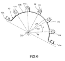
FIG. 6 is a side view of a band according to another embodiment of this invention. - Referring to
FIG. 1 of the drawings, afluid pressure cylinder 1 that drives a boom or the like of a working machine, for example, is formed inside acylinder tube 2 and activated by a working fluid pressure supplied through apipe 4. Working oil, for example, is used as the working fluid. Instead of working oil, a water-soluble replacement liquid or air may be used. - The
pipe 4 is fixed to an outer periphery of thecylinder tube 2 using a pipe fixing structure according to this invention. - The pipe fixing structure includes a pair of
bands 10 wrapped fixedly around an outerperipheral surface 2a of thecylinder tube 2, abracket 20 fixed to theband 10, and aclamp 40 that grips thepipe 4 in combination with thebracket 20. As shown in the figure, thepipe 4 is supported parallel to thecylinder tube 2 via the pipe fixing structure. - Referring to
FIGs. 2 and3 , theband 10 is formed from sheet metal. Theband 10 is constituted by a band plate-shapedmain body portion 10b fixed to the outerperipheral surface 2a of thecylinder tube 2, a first pair oftabs 11a that project radially outward from either axial end of themain body portion 10b fixed to the outerperipheral surface 2a of thecylinder tube 2, and a similar second pair oftabs 11b provided at an angular interval θ from the first pair oftabs 11a. Themain body portion 10b is formed with an arc-shaped cross-section of substantially 180 degrees in order to cover substantially half of the circumference of thecylinder tube 2. A joiningportion 10a bent in a radial direction is formed on either circumferential direction end of themain body portion 10b. A joininghole 10c is formed in each joiningportion 10a. - Referring back to
FIG. 1 , theband 10 is fixed to thecylinder tube 2 as follows. The twobands 10 are wrapped around thecylinder tube 2 such that the joiningportions 10a of oneband 10 oppose the joiningportions 10a of theother band 10, whereupon tip ends ofbolts 5 inserted into the joiningholes 10c formed in the opposing joiningportions 10a are screwed tonuts 6. Thenuts 6 are fixed to one of the joiningportions 10a of eachband 10 in advance by welding. - Assuming that an outer diameter of the
cylinder tube 2 is D, a cross-section of themain body portion 10b of theband 10 forms an arc having a curvature radius of substantially D/2. - In the
band 10, themain body portion 10b , the joiningportions 10a, the first pair oftabs 11a, and the second pair oftabs 11b are formed integrally in advance by press-molding sheet metal cut into predetermined shapes. When the pipe fixing structure is applied to acylinder tube 2 having a different outer diameter, a band having a curvature radius R that is 1/2 the outer diameter D of thecylinder tube 2 is used. - Fixing
holes 12 for fixing thebracket 20 are formed coaxially in the first pair oftabs 11a and the second pair oftabs 11b, respectively. Thefixing holes 12 are preferably formed as elongated holes extending in a radial direction so that minute adjustments can be made to relative positions of theband 10 and thebracket 20. - The
bracket 20 is constituted by a pair ofleg plate portions 20a, and atop plate portion 20b formed integrally with theleg plate portions 20a to join theleg plate portions 20a. Thebracket 20 thus formed has an inverted U-shaped cross-section. In the figures, thetop plate portion 20b is formed to be flat, but thetop plate portion 20b may be formed with an arched cross-section. - The
leg plate portion 20a is formed with afirst bolt hole 22 having a circular cross-section and asecond bolt hole 23 having an elliptical cross-section. Thesecond bolt hole 23 having the elliptical cross-section is formed along a bolt hole base line G linking a center of thefirst bolt hole 22 to a center of thesecond bolt hole 23. More precisely, thesecond bolt hole 23 is formed such that a long axis of the elliptical cross-section is positioned on the bolt hole base line G. Twofirst bolt holes 22 and twosecond bolt holes 23 are respectively positioned coaxially in thebracket 20. - A transverse direction dimension of the
bracket 20 is set such that respective inner surfaces of the twoleg plate portions 20a fit onto respective outer surfaces of the first pair oftabs 11a and second pair oftabs 11b. - Referring to
FIGs. 3 and4 , abolt 7 penetrates the twofirst bolt holes 22 in the twoleg plate portions 20a of thebracket 20 and the twofixing holes 12 of the first pair oftabs 11 a positioned on the inside thereof, and anut 17 is fastened to a penetrating end of thebolt 7. Further, abolt 8 penetrates the twosecond bolt holes 23 in the twoleg plate portions 20a and the twofixing holes 12 of the second pair oftabs 11b positioned on the inside thereof, and anut 18 is fastened to a penetrating end of thebolt 8. Thus, thebracket 20 is fixed to theband 10. - A
notch 20d for receiving thepipe 4 is formed in thebracket 20. Thenotch 20d has an arc-shaped cross-section that is oriented radially outward when seen from a direction of acentral axis 02 of thecylinder tube 2 in a state where thebracket 20 is fixed to thecylinder tube 2 via theband 10. - The
bracket 20 is formed integrally by press-molding sheet metal cut in advance into a predetermined shape including thenotch 20d. - The
clamp 40 is constituted by a flat plate-shaped base portion 40a fixed to thetop plate portion 20b by abolt 9 and anut 19, and atip end portion 40b formed integrally with one end of thebase portion 40a. A hole 20e for fixing thebase portion 40a is formed in thetop plate portion 20b of thebracket 20. Thenut 19 is fixed to a periphery of the hole 20e in advance by welding. Thetip end portion 40b is formed with an arc-shaped cross-section that corresponds to thenotch 20d formed in thebracket 20. Theclamp 40 is formed by press-molding sheet metal cut in advance into a predetermined shape. - To fix the
pipe 4 to thebracket 20, thebase portion 40a of theclamp 40 is fixed to thetop plate portion 20b by thebolt 9 and thenut 19 while thepipe 4 is seated on thenotch 20d. As a result, thepipe 4 is sandwiched between thebracket 20 and theclamp 40 supported on thebracket 20 in cantilever fashion, and therefore thepipe 4 is prevented from falling out of thenotch 20d. - Here, the arc-shaped cross-section of the
notch 20d in thebracket 20 and the arc-shaped cross-section of thetip end portion 40b of theclamp 40 are both set with a radius R. The pipe fixing structure has been designed with the aim of supporting apipe 4A having the radius R, apipe 4B having a smaller diameter than thepipe 4A, or apipe 4C having an even smaller diameter. In other words, the radius R is set to be equal to a maximum pipe diameter that can be supported by thebracket 20. When the pipe fixing structure is applied to thepipe 4B or thepipe 4C, aclamp 40 having a smaller radius R on the arc-shaped cross-section of thetip end portion 40b is used. In other words, according to this pipe fixing structure, a plurality ofpipes 4 having difference radii R can be accommodated by replacing theclamp 40 alone, i.e. without replacing thebracket 20. - On the other hand, if the
clamp 40 is formed by a spring material that is capable of elastic deformation in the radial direction of the figure,pipes 4 of different diameters can be held in thenotch 20d using thesame clamp 40. In this case, theclamp 40 is preferably formed with a cantilever structure in which thebase portion 40a is fixed so that theclamp 40 is capable of elastic deformation in the radial direction of theclamp 40. - Referring to
FIG. 5A , an angle θ is formed by a straight line F1 linking thecentral axis 02 of thecylinder tube 2 to acenter 07 of the fixing holes 12 in the first pair oftabs 11a and a straight line F2 linking thecentral axis 02 of thecylinder tube 2 to acenter 08 of the fixing holes 12 in the second pair oftabs 11b. The angle θ corresponds to the aforementioned angular interval between the first pair oftabs 11a and the second pair oftabs 11b. - In this pipe fixing structure,
bands 10 having different diameters are used in accordance with variation in the outer diameter D of thecylinder tube 2. As regards thebracket 20, on the other hand, thesame bracket 20 is used in relation tobands 10 having different diameters. - In the figures, the
second bolt 8 penetrates the center of the ellipticalsecond bolt hole 23. The outer diameter D of thecylinder tube 2 at this time is set as a standard diameter. When theband 10 is used on acylinder tube 2 having a larger outer diameter D than the standard diameter, aband 10 having a correspondingly larger diameter is used. In this case, the position in which thesecond bolt 8 penetrates thesecond bolt hole 23 is displaced from the center of thesecond bolt hole 23 in a direction heading away from thefirst bolt hole 22. Conversely, when the outer diameter D of thecylinder tube 2 is smaller than the standard diameter, aband 10 having a correspondingly smaller diameter is used. In this case, the position in which thesecond bolt 8 penetrates thesecond bolt hole 23 is displaced from the center of thesecond bolt hole 23 in a direction approaching thefirst bolt hole 22. - In this way,
bands 10 having different diameters are used in accordance with differences in the outer diameter D of thecylinder tube 2. Regardless of the diameter of theband 10, formation positions of thefirst tabs 11a andsecond tabs 11b are set in advance such that the angle θ between the straight lines F1 and F2 remains constant. - Meanwhile, to ensure that the
same bracket 20 can be used in the pipe fixing structure regardless of differences in the diameter of theband 10, an angle α formed by a straight line E that passes through thecenter 07 of thefirst bolt 7 orthogonally to the straight line F1 and the aforesaid bolt hole base line G is set to be 1/2 the angle θ formed by the straight lines F1 and F2. - In the figures, a distance from the
central axis 02 of thecylinder tube 2 to thecenter 07 of thefirst bolt 7 is set to be equal to a distance from thecentral axis 02 of thecylinder tube 2 to thecenter 08 of thesecond bolt 8. This distance is set as L. The distance L is expressed by a following equation.
peripheral surface 2a of thecylinder tube 2 to the center O7 of thefirst bolt 7 or the center O8 of thesecond bolt 8. - The distance H is set in advance such that the
pipe 4 does not interfere with thecylinder tube 2. The distance H remains constant regardless of the diameter of theband 10. - Referring to
FIG. 5B , a distance X between thecenter 07 of thefirst bolt 7 and thecenter 08 of thesecond bolt 8 along the straight line F1 is expressed by a following equation.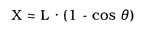
- A distance Y between the
center 07 of thefirst bolt 7 and thecenter 08 of thesecond bolt 8 along the straight line E, which is orthogonal to the straight line F1, is expressed by a following equation.
- Further, a distance Z between the
center 07 of thefirst bolt 7 and thecenter 08 of thesecond bolt 8 is expressed by a following equation.
- When
bands 10 of different diameters are used, the distance Z also varies. A length P of thesecond bolt hole 23 is therefore set in accordance with a maximum value and a minimum value of the distance Z. - As described above, in this pipe fixing structure, the
first tabs 11a andsecond tabs 11b are disposed such that the angle θ and the distance H are respectively maintained at constant values in relation tobands 10 of different diameters, while thesecond bolt hole 23 in thebracket 20 is formed as an elongated hole extending along the bolt hole base line G. - By performing setting in this manner, the
bracket 20 fixed to thebands 10 of various diameters maintains the angle α and the distance H shown inFIG. 5A relative to theband 10 at all times. Therefore, even when thepipe 4 is fixed to acylinder tube 2 having a different outer diameter D, the distance and position relationship between thecylinder tube 2 and thepipe 4 can be kept constant at all times using thesame bracket 20. - It should be noted that the
second bolt hole 23 may be formed as a rounded hole rather than an elongated hole and thefirst bolt hole 22 may be formed as an elongated hole extending along the bolt hole base line G. - According to the pipe fixing structure described above, by employing the
bands 10 of different diameters and thesingle bracket 20,pipes 4 of various radii R can be fixed tocylinder tubes 2 of various outer diameters D while maintaining a constant distance and position relationship relative thereto. Therefore, the number of components required in the pipe fixing structure can be reduced, enabling a reduction in the cost of fixing thepipe 4 to thecylinder tube 2. - Further, the
band 10, thebracket 20, and theclamp 40 are respectively formed by press-molding sheet metal cut into predetermined shapes, and therefore the constitutional components of the pipe fixing structure can be manufactured easily and at a low weight. Thebracket 20 is formed with an inverted U-shaped cross-section constituted by the twoleg plate portions 20a fixed to thetabs 11aleg plate portion 20a joining theleg plate portions 20a, and therefore thepipe 4 can be supported with a high degree of rigidity. - In this embodiment, the
bracket 20 supports thesingle pipe 4, but thebracket 20 may support a plurality of pipes. - In this embodiment, the
bracket 20 is fixed to theband 10 by screwing the nut 17 (18) to the bolt 7 (8) that penetrates the pair oftabs 11a (11b) and the twoleg plate portions 20a of thebracket 20. However, thebracket 20 may be fixed to theband 10 using a total of four bolts and four nuts by joining one of thetabs 11a (11b) and one of theleg plate portions 20a with a bolt and a nut. In this case, eachleg plate portion 20a is fixed to eachtab 11a (11b) individually, and therefore a further improvement in support rigidity can be achieved in relation to a collapsing direction of theleg plate portions 20a. - Further, the structure for fixing the
bracket 20 to theband 10 is not limited to a fixing structure using a bolt and a nut. - In this embodiment, the
base portion 40a of theclamp 40 is supported on thetop plate portion 20b by a cantilever structure fixed by thebolt 9 and thenut 19. However, a separate base portion may be provided on a tip end of thetip end portion 40b on the opposite side of theclamp 40 to thebase portion 40a, and the two base portions may be fixed to thebracket 20 individually by bolts. - Referring to
FIG. 6 , a second embodiment of this invention relating to the constitution of theband 10 will be described. - Five pairs of
tabs 11a-11e are formed at equal angular intervals θ around the outer periphery of themain body portion 10b of theband 10 according to this embodiment. By forming three or more pairs of tabs on the outer periphery of themain body portion 10b in this manner, the number of options relating to the position in which thebracket 20 is attached to theband 10 in the circumferential direction can be increased. Further, when four or more pairs of tabs are formed on the outer periphery of themain body portion 10b, twobrackets 20 can be fixed to asingle band 10. - The contents of Tokugan 2009-104887 and Tokugan 2009-104889, with a filing date of April 23, 2009 in Japan, are hereby incorporated by reference.
- Although the invention has been described above with reference to certain embodiments, the invention is not limited to the embodiments described above. Modifications and variations of the embodiments described above will occur to those skilled in the art, within the scope of the claims.
- As described above, this invention is applied to a fluid pressure cylinder for a working machine, but the scope of application of this invention is not limited thereto.
- The embodiments of this invention in which an exclusive property or privilege is claimed are defined as follows:
Claims (10)
- A pipe fixing structure that supports a pipe (4) on a cylinder tube (2), comprising:a band (10) fastened to an outer periphery (2a) of the cylinder tube (2), the band (10) comprising a first tab (11a) that projects outward in a radial direction and a second tab (11b) that projects outward in the radial direction; anda bracket (20) that supports the pipe (4),wherein the bracket (20) is formed with an inverted U-shaped cross-section constituted by a pair of leg plate portions (20a) and a top plate portion (20b) formed integrally with the leg plate portions (20a) to join the leg plate portions (20a), andthe pair of leg plate portions (20a) are fixed to the first tab (11a) and the second tab (11b) by a bolt.
- The pipe fixing structure as defined in Claim 1, wherein the bracket (20) includes a notch (20d) for supporting the pipe (4), the notch (20d) having an arc-shaped cross-section that is oriented outward when seen from an axial direction of the cylinder tube (2) in a state where the pair of leg plate portions (20a) are fixed to the first tab (11a) and the second tab (11b).
- The pipe fixing structure as defined in Claim 1 or Claim 2, wherein the band (10) and the bracket (20) are respectively formed by press-molding.
- The pipe fixing structure as defined in any one of Claim 1 to Claim 3, wherein the cylinder tube (2) has a central axis (02),
the bracket (20) includes a first bolt hole (22) and a second bolt hole (23),
a fixing hole (12) is formed in each of the first tab (11a) and the second tab (11b),
the fixing hole (12) in the first tab (11a) and the fixing hole (12) in the second tab (11b) form an angle θ about the central axis (02),
a first bolt (7) that penetrates the first bolt hole (22) and the fixing hole (12) in the first tab (11a) to fix the bracket (20) to the first tab (11a) and a second bolt (8) that penetrates the second bolt hole (23) and the fixing hole (12) in the second tab (11b) to fix the bracket (20) to the second tab (11b) are provided,
at least one of the first bolt hole (22) and the second bolt hole (23) is formed as an elongated hole extending in a direction of a bolt hole base line (G) linking a center of the first bolt hole (22) to a center of the second bolt hole (23), and
an angle α formed by the bolt hole base line (G) and a straight line (E) that is orthogonal to a straight line (F1) linking the central axis (02) to a center of the fixing hole (12) in the first tab (11a) and passes through a center of the first bolt (7) is set at α = 1/2 × θ. - The pipe fixing structure as defined in Claim 4, wherein the band (10) comprises:a pair of first tabs (11a) disposed such that the fixing holes (12) thereof overlap on an axis which is parallel to the central axis (02); anda pair of second tabs (11b) disposed such that the fixing holes (12) thereof overlap on an axis which is parallel to the central axis (02),the first bolt hole (22) is formed in each of the pair of leg plate portions (20a),the second bolt hole (23) is formed in each of the pair of leg plate portions (20a),the first bolt (7) penetrates the first bolt holes (22) in the pair of leg plate portions (20a) and the fixing holes (12) in the pair of first tabs (11a), andthe second bolt (8) penetrates the second bolt holes (23) in the pair of leg plate portions (20a) and the fixing holes (12) in the pair of second tabs (11b).
- The pipe fixing structure as defined in Claim 5, wherein the band (10) includes three or more tabs (11a-11e) disposed at angles θ in a circumferential direction.
- The pipe fixing structure as defined in Claim 5 or Claim 6, wherein the fixing hole (12) in the first tab (11a) and the fixing hole (12) in the second tab (11b) are both formed as elongated holes extending in the radial direction.
- The pipe fixing structure as defined in any one of Claim 5 to Claim 7, wherein the top plate portion (20b) is formed to be flat, and the pipe fixing structure further comprises a clamp (40) that includes a base portion (40a) fixed to the top plate portion (20b) and a tip end portion (40b) that is formed integrally with the base portion (40a) and has an arc-shaped cross-section corresponding to the notch (20d) such that the clamp (40) sandwiches the pipe (4) between the notch (20d) and the tip end portion (40b).
- The pipe fixing structure as defined in any one of Claim 1 to Claim 8, wherein the band (10) has an arc-shaped cross-section of substantially 180 degrees and includes a joining hole (10c) in either circumferential direction end thereof, and by disposing a pair of the bands (10) on the outer periphery of the cylinder tube (2) such that the respective joining holes (10c) oppose each other and fastening the opposing joining holes (10c) together using a bolt and a nut, the bands (10) are fixed to the outer periphery of the cylinder tube (2).
- A fluid pressure cylinder (1) that supports a pipe (4) on a cylinder tube (2), comprising:a band (10) fastened to an outer periphery (2a) of the cylinder tube (2), the band (10) comprising a first tab (11a) that projects outward in a radial direction and a second tab (11b) that projects outward in the radial direction; anda bracket (20) that supports the pipe (4),wherein the bracket (20) is formed with an inverted U-shaped cross-section constituted by a pair of leg plate portions (20a) and a top plate portion (20b) formed integrally with the leg plate portions (20a) to join the leg plate portions (20a), andthe pair of leg plate portions (20a) are fixed to the first tab (11a) and the second tab (11b) by a bolt.
Applications Claiming Priority (3)
| Application Number | Priority Date | Filing Date | Title |
|---|---|---|---|
| JP2009104889A JP5111429B2 (en) | 2009-04-23 | 2009-04-23 | Fluid pressure cylinder and piping fixing structure |
| JP2009104887A JP5344979B2 (en) | 2009-04-23 | 2009-04-23 | Fluid pressure cylinder and piping fixing structure |
| PCT/JP2010/056042 WO2010122891A1 (en) | 2009-04-23 | 2010-03-26 | Pipe securing structure for cylinder tube |
Publications (3)
| Publication Number | Publication Date |
|---|---|
| EP2423516A1 true EP2423516A1 (en) | 2012-02-29 |
| EP2423516A4 EP2423516A4 (en) | 2014-02-26 |
| EP2423516B1 EP2423516B1 (en) | 2016-03-16 |
Family
ID=43011013
Family Applications (1)
| Application Number | Title | Priority Date | Filing Date |
|---|---|---|---|
| EP10766950.9A Not-in-force EP2423516B1 (en) | 2009-04-23 | 2010-03-26 | Pipe securing structure for cylinder tube |
Country Status (5)
| Country | Link |
|---|---|
| US (1) | US8413934B2 (en) |
| EP (1) | EP2423516B1 (en) |
| KR (1) | KR101248660B1 (en) |
| CN (1) | CN102084137B (en) |
| WO (1) | WO2010122891A1 (en) |
Families Citing this family (15)
| Publication number | Priority date | Publication date | Assignee | Title |
|---|---|---|---|---|
| US8991774B2 (en) * | 2011-12-22 | 2015-03-31 | Panduit Corp. | Cable tie mount |
| US9093830B2 (en) * | 2012-07-12 | 2015-07-28 | Rockwell Automation Technologies, Inc. | Cable clamp assembly with double captive screw |
| JP6070213B2 (en) * | 2013-01-24 | 2017-02-01 | Kyb株式会社 | Piping fixture for fluid pressure cylinder and manufacturing method thereof |
| JP5993774B2 (en) * | 2013-03-28 | 2016-09-14 | Kyb株式会社 | Piping fixture for fluid pressure cylinder |
| JP5993773B2 (en) * | 2013-03-28 | 2016-09-14 | Kyb株式会社 | Piping fixture for fluid pressure cylinder |
| US8857084B2 (en) | 2013-05-20 | 2014-10-14 | Gary Courter | Mobile advertising displays |
| US9640095B2 (en) * | 2013-12-23 | 2017-05-02 | Chien-Ting Lin | Photography light panel reflector clamp |
| US20150176822A1 (en) * | 2013-12-23 | 2015-06-25 | Chien-Ting Lin | Light reflector clamp |
| JP6408808B2 (en) * | 2014-07-10 | 2018-10-17 | 三菱重工サーマルシステムズ株式会社 | Electric compressor |
| AU2015355064B2 (en) * | 2014-12-03 | 2019-06-20 | Icon Vehicle Dynamics Llc | Shock absorbers |
| GB201610790D0 (en) * | 2016-06-21 | 2016-08-03 | Advanced Insulation Plc | Mounting arrangement |
| CN106143651A (en) * | 2016-08-09 | 2016-11-23 | 南京创源天地动力科技有限公司 | A kind of gas receiver anchor ear in passenger vehicle |
| JP2018155408A (en) * | 2018-05-22 | 2018-10-04 | Kyb−Ys株式会社 | Apparatus attachment structure |
| US11851833B1 (en) * | 2018-06-14 | 2023-12-26 | Ameristar Perimeter Security Usa Inc. | Cable barrier |
| CN112856234B (en) * | 2021-03-01 | 2024-03-29 | 西安奥腾石油工程技术服务有限公司 | High-pressure pipeline assembly |
Family Cites Families (41)
| Publication number | Priority date | Publication date | Assignee | Title |
|---|---|---|---|---|
| US978398A (en) * | 1910-03-11 | 1910-12-13 | Joseph J Rischard | Hose-clamp. |
| US1774775A (en) * | 1929-05-09 | 1930-09-02 | Jr John A Weitz | Bracket for electric lights and flash lights |
| US3385545A (en) * | 1966-02-09 | 1968-05-28 | Robert P. Patton | Conduit hanging apparatus |
| GB1427922A (en) | 1972-03-03 | 1976-03-10 | Unilever Ltd | Stabilized additive |
| JPS5322681Y2 (en) * | 1972-03-13 | 1978-06-13 | ||
| US4103853A (en) * | 1976-12-22 | 1978-08-01 | Mcgraw-Edison Company | Aluminum cluster mount |
| JPS61187861A (en) | 1985-02-14 | 1986-08-21 | 松下電工株式会社 | Massager |
| JPS61187861U (en) * | 1985-05-14 | 1986-11-22 | ||
| ES2018490B3 (en) * | 1986-03-26 | 1991-04-16 | Siemens Ag | MECHANISM FOR THE MECHANICAL UNCOUPLING OF A PIPING SYSTEM |
| DE3621484A1 (en) * | 1986-06-24 | 1988-01-21 | Hubert Combe | PIPE CLAMP FOR SELECTIVE PENDING AND RIGID SUSPENSION OF PIPES |
| JP2700006B2 (en) | 1987-10-19 | 1998-01-19 | カシオ計算機株式会社 | Liquid crystal display device |
| US6408492B1 (en) * | 1988-03-21 | 2002-06-25 | Ronald V. Sparks | Holder for slender elongated articles such as fishing rod sections |
| US5035383A (en) * | 1989-02-16 | 1991-07-30 | Rockwell International Corporation | Space saver service clamp |
| US5193774A (en) * | 1992-05-26 | 1993-03-16 | Rogers J W | Mounting bracket apparatus |
| JPH0656506A (en) | 1992-06-05 | 1994-03-01 | Veitscher Magnesitwerke Ag | Production of ceramic material and its molding using finely powdered fire-proofing oxide |
| US5703330A (en) * | 1992-11-16 | 1997-12-30 | Bundy Corporation | Wire harness conduit and tube bundle |
| JPH0656506U (en) * | 1993-01-20 | 1994-08-05 | カヤバ工業株式会社 | Hydraulic cylinder piping fixing structure |
| US5320312A (en) * | 1993-05-05 | 1994-06-14 | Stainless, Inc. | Cable cluster mount |
| US5405113A (en) * | 1994-01-24 | 1995-04-11 | Jaw; Chin-Woei | Bicycle padlock holder |
| DE4432780A1 (en) * | 1994-09-15 | 1996-03-21 | Hilti Ag | Pipe and cable clamp with foot section and mounting bracket |
| DE4432781A1 (en) * | 1994-09-15 | 1996-03-21 | Hilti Ag | Pipe and cable clamp with foot section and mounting bracket |
| JP3520458B2 (en) * | 1994-12-14 | 2004-04-19 | カヤバ工業株式会社 | Knuckle bracket |
| US5689862A (en) * | 1996-05-02 | 1997-11-25 | Spm, Inc. | Safety clamp |
| US5897082A (en) * | 1997-07-08 | 1999-04-27 | Losada; Al | Power actuated fastener for pipe |
| US6095386A (en) * | 1999-06-29 | 2000-08-01 | Kuo; Lambert | Bicycle lock mounting bracket |
| JP2001314012A (en) * | 2000-02-21 | 2001-11-09 | Inoac Corp | Vehicle wire holding member |
| DE10115373C1 (en) * | 2001-03-28 | 2002-10-17 | Zf Sachs Ag | Articulated support for a piston-cylinder unit |
| US6486402B2 (en) * | 2001-04-18 | 2002-11-26 | Harger, Inc. | Cable grounding clamp |
| JP4017561B2 (en) * | 2003-06-02 | 2007-12-05 | イワブチ株式会社 | Device for supporting the vertical part of armrests for equipment columns made of cylinders |
| US20050045786A1 (en) * | 2003-08-25 | 2005-03-03 | Tupper Robert Roy | Framework for supporting plants |
| US7140579B2 (en) * | 2004-04-20 | 2006-11-28 | Automatic Fire Control, Incorporated | Sway brace clamp |
| GB0512243D0 (en) * | 2005-06-16 | 2005-07-27 | Aube Francois | Medical bag support |
| ITPD20050248A1 (en) * | 2005-08-05 | 2007-02-06 | Moretto P A Srl | FIXING DEVICE FOR PIPELINES WITH BEARING STRUCTURES |
| US7481401B2 (en) * | 2005-08-23 | 2009-01-27 | Trw Automotive U.S. Llc | Tube assembly one piece bracket |
| JP2008056506A (en) * | 2006-08-29 | 2008-03-13 | Toda Kogyo Corp | Silicic acid-covered hydrotalcite compound particle powder, and chlorine-containing resin stabilizer and chlorine-containing resin composition using the particle powder |
| JP2008057606A (en) * | 2006-08-30 | 2008-03-13 | Kayaba Ind Co Ltd | Fluid pressure cylinder and piping fixing structure |
| NL1033138C2 (en) * | 2006-12-27 | 2008-06-30 | Walraven Holding Bv J Van | Pipe bracket. |
| CN200998551Y (en) * | 2007-01-25 | 2008-01-02 | 向丽如 | Trampoline surrounding net pipe fixing component |
| EP2003818B1 (en) | 2007-06-13 | 2018-11-28 | EXFO Oy | A man-in-the-middle detector and a method using It |
| US8608121B2 (en) * | 2007-07-06 | 2013-12-17 | Kabushiki Kaisha Toshiba | Device and method for fixing a reactor metering pipe |
| US7835715B2 (en) | 2007-10-17 | 2010-11-16 | Broadcom Corporation | Log-antilog mixer circuit and method for producing frequency conversion |
-
2010
- 2010-03-26 KR KR1020107027582A patent/KR101248660B1/en not_active Expired - Fee Related
- 2010-03-26 EP EP10766950.9A patent/EP2423516B1/en not_active Not-in-force
- 2010-03-26 CN CN2010800020132A patent/CN102084137B/en not_active Expired - Fee Related
- 2010-03-26 WO PCT/JP2010/056042 patent/WO2010122891A1/en not_active Ceased
- 2010-03-26 US US12/996,048 patent/US8413934B2/en not_active Expired - Fee Related
Non-Patent Citations (2)
| Title |
|---|
| No further relevant documents disclosed * |
| See also references of WO2010122891A1 * |
Also Published As
| Publication number | Publication date |
|---|---|
| US8413934B2 (en) | 2013-04-09 |
| CN102084137A (en) | 2011-06-01 |
| US20110073719A1 (en) | 2011-03-31 |
| EP2423516B1 (en) | 2016-03-16 |
| WO2010122891A1 (en) | 2010-10-28 |
| EP2423516A4 (en) | 2014-02-26 |
| CN102084137B (en) | 2013-10-16 |
| KR20110005309A (en) | 2011-01-17 |
| KR101248660B1 (en) | 2013-03-28 |
Similar Documents
| Publication | Publication Date | Title |
|---|---|---|
| EP2423516B1 (en) | Pipe securing structure for cylinder tube | |
| US6883761B2 (en) | Support for tubular members | |
| US10556506B2 (en) | Tank fixing apparatus | |
| EP2997291B1 (en) | Flexible conduit element | |
| JP6001495B2 (en) | Bracket for vibration isolator | |
| US9765680B2 (en) | Support ring for an exhaust gas duct system | |
| JP5719188B2 (en) | Brace mounting bracket and ceiling structure | |
| JP5993774B2 (en) | Piping fixture for fluid pressure cylinder | |
| EP2600475B1 (en) | Anti-rotation cable restraint for connecting flexible ducts | |
| JP2010255709A (en) | Fluid pressure cylinder and piping fixing structure | |
| JP5344979B2 (en) | Fluid pressure cylinder and piping fixing structure | |
| JP2004100821A (en) | Piping support | |
| JP2008238381A (en) | Proximity sensor mounting structure and workpiece positioning device having the mounting structure | |
| JP6667919B1 (en) | Cylindrical fixture | |
| JP2023041411A (en) | Attachment device | |
| JP2012112399A (en) | Long body cover attaching fixture and long body cover attaching method using the same | |
| JPH06101728A (en) | Vibration control device | |
| JP4306418B2 (en) | Cable support device | |
| JP7274872B2 (en) | Bracket and mounting structure | |
| CN113734053A (en) | Quick-dismantling type fixing ring | |
| JP4292455B2 (en) | Pipe support device | |
| JP5993773B2 (en) | Piping fixture for fluid pressure cylinder | |
| JP2006292037A (en) | Fastening structure of plate body attached to columnar body | |
| JP2024062723A (en) | Curved pipe rotation device | |
| JP2022156891A (en) | torque sensor |
Legal Events
| Date | Code | Title | Description |
|---|---|---|---|
| PUAI | Public reference made under article 153(3) epc to a published international application that has entered the european phase |
Free format text: ORIGINAL CODE: 0009012 |
|
| 17P | Request for examination filed |
Effective date: 20101124 |
|
| AK | Designated contracting states |
Kind code of ref document: A1 Designated state(s): AT BE BG CH CY CZ DE DK EE ES FI FR GB GR HR HU IE IS IT LI LT LU LV MC MK MT NL NO PL PT RO SE SI SK SM TR |
|
| DAX | Request for extension of the european patent (deleted) | ||
| A4 | Supplementary search report drawn up and despatched |
Effective date: 20140123 |
|
| RIC1 | Information provided on ipc code assigned before grant |
Ipc: F16L 3/10 20060101ALI20140117BHEP Ipc: F15B 15/14 20060101AFI20140117BHEP Ipc: F16L 3/237 20060101ALI20140117BHEP |
|
| GRAP | Despatch of communication of intention to grant a patent |
Free format text: ORIGINAL CODE: EPIDOSNIGR1 |
|
| INTG | Intention to grant announced |
Effective date: 20151009 |
|
| GRAS | Grant fee paid |
Free format text: ORIGINAL CODE: EPIDOSNIGR3 |
|
| RAP1 | Party data changed (applicant data changed or rights of an application transferred) |
Owner name: KYB CORPORATION |
|
| GRAA | (expected) grant |
Free format text: ORIGINAL CODE: 0009210 |
|
| RIN1 | Information on inventor provided before grant (corrected) |
Inventor name: HARA, TAKAHIKO |
|
| AK | Designated contracting states |
Kind code of ref document: B1 Designated state(s): AT BE BG CH CY CZ DE DK EE ES FI FR GB GR HR HU IE IS IT LI LT LU LV MC MK MT NL NO PL PT RO SE SI SK SM TR |
|
| REG | Reference to a national code |
Ref country code: GB Ref legal event code: FG4D |
|
| REG | Reference to a national code |
Ref country code: CH Ref legal event code: EP |
|
| REG | Reference to a national code |
Ref country code: IE Ref legal event code: FG4D |
|
| REG | Reference to a national code |
Ref country code: AT Ref legal event code: REF Ref document number: 781504 Country of ref document: AT Kind code of ref document: T Effective date: 20160415 |
|
| REG | Reference to a national code |
Ref country code: DE Ref legal event code: R096 Ref document number: 602010031237 Country of ref document: DE |
|
| REG | Reference to a national code |
Ref country code: NL Ref legal event code: MP Effective date: 20160316 |
|
| REG | Reference to a national code |
Ref country code: LT Ref legal event code: MG4D |
|
| PG25 | Lapsed in a contracting state [announced via postgrant information from national office to epo] |
Ref country code: GR Free format text: LAPSE BECAUSE OF FAILURE TO SUBMIT A TRANSLATION OF THE DESCRIPTION OR TO PAY THE FEE WITHIN THE PRESCRIBED TIME-LIMIT Effective date: 20160617 Ref country code: HR Free format text: LAPSE BECAUSE OF FAILURE TO SUBMIT A TRANSLATION OF THE DESCRIPTION OR TO PAY THE FEE WITHIN THE PRESCRIBED TIME-LIMIT Effective date: 20160316 Ref country code: FI Free format text: LAPSE BECAUSE OF FAILURE TO SUBMIT A TRANSLATION OF THE DESCRIPTION OR TO PAY THE FEE WITHIN THE PRESCRIBED TIME-LIMIT Effective date: 20160316 Ref country code: NO Free format text: LAPSE BECAUSE OF FAILURE TO SUBMIT A TRANSLATION OF THE DESCRIPTION OR TO PAY THE FEE WITHIN THE PRESCRIBED TIME-LIMIT Effective date: 20160616 |
|
| REG | Reference to a national code |
Ref country code: AT Ref legal event code: MK05 Ref document number: 781504 Country of ref document: AT Kind code of ref document: T Effective date: 20160316 |
|
| PG25 | Lapsed in a contracting state [announced via postgrant information from national office to epo] |
Ref country code: LV Free format text: LAPSE BECAUSE OF FAILURE TO SUBMIT A TRANSLATION OF THE DESCRIPTION OR TO PAY THE FEE WITHIN THE PRESCRIBED TIME-LIMIT Effective date: 20160316 Ref country code: LT Free format text: LAPSE BECAUSE OF FAILURE TO SUBMIT A TRANSLATION OF THE DESCRIPTION OR TO PAY THE FEE WITHIN THE PRESCRIBED TIME-LIMIT Effective date: 20160316 Ref country code: BE Free format text: LAPSE BECAUSE OF NON-PAYMENT OF DUE FEES Effective date: 20160331 Ref country code: SE Free format text: LAPSE BECAUSE OF FAILURE TO SUBMIT A TRANSLATION OF THE DESCRIPTION OR TO PAY THE FEE WITHIN THE PRESCRIBED TIME-LIMIT Effective date: 20160316 Ref country code: NL Free format text: LAPSE BECAUSE OF FAILURE TO SUBMIT A TRANSLATION OF THE DESCRIPTION OR TO PAY THE FEE WITHIN THE PRESCRIBED TIME-LIMIT Effective date: 20160316 |
|
| PG25 | Lapsed in a contracting state [announced via postgrant information from national office to epo] |
Ref country code: IS Free format text: LAPSE BECAUSE OF FAILURE TO SUBMIT A TRANSLATION OF THE DESCRIPTION OR TO PAY THE FEE WITHIN THE PRESCRIBED TIME-LIMIT Effective date: 20160716 Ref country code: EE Free format text: LAPSE BECAUSE OF FAILURE TO SUBMIT A TRANSLATION OF THE DESCRIPTION OR TO PAY THE FEE WITHIN THE PRESCRIBED TIME-LIMIT Effective date: 20160316 Ref country code: PL Free format text: LAPSE BECAUSE OF FAILURE TO SUBMIT A TRANSLATION OF THE DESCRIPTION OR TO PAY THE FEE WITHIN THE PRESCRIBED TIME-LIMIT Effective date: 20160316 |
|
| REG | Reference to a national code |
Ref country code: CH Ref legal event code: PL |
|
| PG25 | Lapsed in a contracting state [announced via postgrant information from national office to epo] |
Ref country code: SK Free format text: LAPSE BECAUSE OF FAILURE TO SUBMIT A TRANSLATION OF THE DESCRIPTION OR TO PAY THE FEE WITHIN THE PRESCRIBED TIME-LIMIT Effective date: 20160316 Ref country code: CZ Free format text: LAPSE BECAUSE OF FAILURE TO SUBMIT A TRANSLATION OF THE DESCRIPTION OR TO PAY THE FEE WITHIN THE PRESCRIBED TIME-LIMIT Effective date: 20160316 Ref country code: PT Free format text: LAPSE BECAUSE OF FAILURE TO SUBMIT A TRANSLATION OF THE DESCRIPTION OR TO PAY THE FEE WITHIN THE PRESCRIBED TIME-LIMIT Effective date: 20160718 Ref country code: RO Free format text: LAPSE BECAUSE OF FAILURE TO SUBMIT A TRANSLATION OF THE DESCRIPTION OR TO PAY THE FEE WITHIN THE PRESCRIBED TIME-LIMIT Effective date: 20160316 Ref country code: SM Free format text: LAPSE BECAUSE OF FAILURE TO SUBMIT A TRANSLATION OF THE DESCRIPTION OR TO PAY THE FEE WITHIN THE PRESCRIBED TIME-LIMIT Effective date: 20160316 Ref country code: ES Free format text: LAPSE BECAUSE OF FAILURE TO SUBMIT A TRANSLATION OF THE DESCRIPTION OR TO PAY THE FEE WITHIN THE PRESCRIBED TIME-LIMIT Effective date: 20160316 Ref country code: AT Free format text: LAPSE BECAUSE OF FAILURE TO SUBMIT A TRANSLATION OF THE DESCRIPTION OR TO PAY THE FEE WITHIN THE PRESCRIBED TIME-LIMIT Effective date: 20160316 |
|
| REG | Reference to a national code |
Ref country code: DE Ref legal event code: R097 Ref document number: 602010031237 Country of ref document: DE |
|
| REG | Reference to a national code |
Ref country code: IE Ref legal event code: MM4A |
|
| PG25 | Lapsed in a contracting state [announced via postgrant information from national office to epo] |
Ref country code: BE Free format text: LAPSE BECAUSE OF FAILURE TO SUBMIT A TRANSLATION OF THE DESCRIPTION OR TO PAY THE FEE WITHIN THE PRESCRIBED TIME-LIMIT Effective date: 20160316 Ref country code: IT Free format text: LAPSE BECAUSE OF FAILURE TO SUBMIT A TRANSLATION OF THE DESCRIPTION OR TO PAY THE FEE WITHIN THE PRESCRIBED TIME-LIMIT Effective date: 20160316 |
|
| PLBE | No opposition filed within time limit |
Free format text: ORIGINAL CODE: 0009261 |
|
| STAA | Information on the status of an ep patent application or granted ep patent |
Free format text: STATUS: NO OPPOSITION FILED WITHIN TIME LIMIT |
|
| PG25 | Lapsed in a contracting state [announced via postgrant information from national office to epo] |
Ref country code: IE Free format text: LAPSE BECAUSE OF NON-PAYMENT OF DUE FEES Effective date: 20160326 Ref country code: DK Free format text: LAPSE BECAUSE OF FAILURE TO SUBMIT A TRANSLATION OF THE DESCRIPTION OR TO PAY THE FEE WITHIN THE PRESCRIBED TIME-LIMIT Effective date: 20160316 Ref country code: CH Free format text: LAPSE BECAUSE OF NON-PAYMENT OF DUE FEES Effective date: 20160331 Ref country code: LI Free format text: LAPSE BECAUSE OF NON-PAYMENT OF DUE FEES Effective date: 20160331 |
|
| REG | Reference to a national code |
Ref country code: FR Ref legal event code: ST Effective date: 20170116 |
|
| 26N | No opposition filed |
Effective date: 20161219 |
|
| PG25 | Lapsed in a contracting state [announced via postgrant information from national office to epo] |
Ref country code: BG Free format text: LAPSE BECAUSE OF FAILURE TO SUBMIT A TRANSLATION OF THE DESCRIPTION OR TO PAY THE FEE WITHIN THE PRESCRIBED TIME-LIMIT Effective date: 20160616 |
|
| GBPC | Gb: european patent ceased through non-payment of renewal fee |
Effective date: 20160616 |
|
| PG25 | Lapsed in a contracting state [announced via postgrant information from national office to epo] |
Ref country code: FR Free format text: LAPSE BECAUSE OF NON-PAYMENT OF DUE FEES Effective date: 20160517 |
|
| PG25 | Lapsed in a contracting state [announced via postgrant information from national office to epo] |
Ref country code: GB Free format text: LAPSE BECAUSE OF NON-PAYMENT OF DUE FEES Effective date: 20160616 Ref country code: SI Free format text: LAPSE BECAUSE OF FAILURE TO SUBMIT A TRANSLATION OF THE DESCRIPTION OR TO PAY THE FEE WITHIN THE PRESCRIBED TIME-LIMIT Effective date: 20160316 |
|
| PG25 | Lapsed in a contracting state [announced via postgrant information from national office to epo] |
Ref country code: MT Free format text: LAPSE BECAUSE OF FAILURE TO SUBMIT A TRANSLATION OF THE DESCRIPTION OR TO PAY THE FEE WITHIN THE PRESCRIBED TIME-LIMIT Effective date: 20160316 |
|
| PG25 | Lapsed in a contracting state [announced via postgrant information from national office to epo] |
Ref country code: HU Free format text: LAPSE BECAUSE OF FAILURE TO SUBMIT A TRANSLATION OF THE DESCRIPTION OR TO PAY THE FEE WITHIN THE PRESCRIBED TIME-LIMIT; INVALID AB INITIO Effective date: 20100326 Ref country code: CY Free format text: LAPSE BECAUSE OF FAILURE TO SUBMIT A TRANSLATION OF THE DESCRIPTION OR TO PAY THE FEE WITHIN THE PRESCRIBED TIME-LIMIT Effective date: 20160316 |
|
| PG25 | Lapsed in a contracting state [announced via postgrant information from national office to epo] |
Ref country code: TR Free format text: LAPSE BECAUSE OF FAILURE TO SUBMIT A TRANSLATION OF THE DESCRIPTION OR TO PAY THE FEE WITHIN THE PRESCRIBED TIME-LIMIT Effective date: 20160316 Ref country code: MC Free format text: LAPSE BECAUSE OF FAILURE TO SUBMIT A TRANSLATION OF THE DESCRIPTION OR TO PAY THE FEE WITHIN THE PRESCRIBED TIME-LIMIT Effective date: 20160316 Ref country code: MT Free format text: LAPSE BECAUSE OF FAILURE TO SUBMIT A TRANSLATION OF THE DESCRIPTION OR TO PAY THE FEE WITHIN THE PRESCRIBED TIME-LIMIT Effective date: 20160331 Ref country code: LU Free format text: LAPSE BECAUSE OF NON-PAYMENT OF DUE FEES Effective date: 20160326 Ref country code: MK Free format text: LAPSE BECAUSE OF FAILURE TO SUBMIT A TRANSLATION OF THE DESCRIPTION OR TO PAY THE FEE WITHIN THE PRESCRIBED TIME-LIMIT Effective date: 20160316 |
|
| PGFP | Annual fee paid to national office [announced via postgrant information from national office to epo] |
Ref country code: DE Payment date: 20200320 Year of fee payment: 11 |
|
| REG | Reference to a national code |
Ref country code: DE Ref legal event code: R119 Ref document number: 602010031237 Country of ref document: DE |
|
| PG25 | Lapsed in a contracting state [announced via postgrant information from national office to epo] |
Ref country code: DE Free format text: LAPSE BECAUSE OF NON-PAYMENT OF DUE FEES Effective date: 20211001 |