EP2422985A1 - Liquid ejection head - Google Patents
Liquid ejection head Download PDFInfo
- Publication number
- EP2422985A1 EP2422985A1 EP11002371A EP11002371A EP2422985A1 EP 2422985 A1 EP2422985 A1 EP 2422985A1 EP 11002371 A EP11002371 A EP 11002371A EP 11002371 A EP11002371 A EP 11002371A EP 2422985 A1 EP2422985 A1 EP 2422985A1
- Authority
- EP
- European Patent Office
- Prior art keywords
- face
- piezoelectric layer
- extended portion
- dummy
- direction perpendicular
- Prior art date
- Legal status (The legal status is an assumption and is not a legal conclusion. Google has not performed a legal analysis and makes no representation as to the accuracy of the status listed.)
- Granted
Links
Images


Classifications
-
- B—PERFORMING OPERATIONS; TRANSPORTING
- B41—PRINTING; LINING MACHINES; TYPEWRITERS; STAMPS
- B41J—TYPEWRITERS; SELECTIVE PRINTING MECHANISMS, i.e. MECHANISMS PRINTING OTHERWISE THAN FROM A FORME; CORRECTION OF TYPOGRAPHICAL ERRORS
- B41J2/00—Typewriters or selective printing mechanisms characterised by the printing or marking process for which they are designed
- B41J2/005—Typewriters or selective printing mechanisms characterised by the printing or marking process for which they are designed characterised by bringing liquid or particles selectively into contact with a printing material
- B41J2/01—Ink jet
- B41J2/135—Nozzles
- B41J2/14—Structure thereof only for on-demand ink jet heads
- B41J2/14201—Structure of print heads with piezoelectric elements
- B41J2/14209—Structure of print heads with piezoelectric elements of finger type, chamber walls consisting integrally of piezoelectric material
- B41J2002/14217—Multi layer finger type piezoelectric element
-
- B—PERFORMING OPERATIONS; TRANSPORTING
- B41—PRINTING; LINING MACHINES; TYPEWRITERS; STAMPS
- B41J—TYPEWRITERS; SELECTIVE PRINTING MECHANISMS, i.e. MECHANISMS PRINTING OTHERWISE THAN FROM A FORME; CORRECTION OF TYPOGRAPHICAL ERRORS
- B41J2/00—Typewriters or selective printing mechanisms characterised by the printing or marking process for which they are designed
- B41J2/005—Typewriters or selective printing mechanisms characterised by the printing or marking process for which they are designed characterised by bringing liquid or particles selectively into contact with a printing material
- B41J2/01—Ink jet
- B41J2/135—Nozzles
- B41J2/14—Structure thereof only for on-demand ink jet heads
- B41J2/14201—Structure of print heads with piezoelectric elements
- B41J2/14209—Structure of print heads with piezoelectric elements of finger type, chamber walls consisting integrally of piezoelectric material
- B41J2002/14225—Finger type piezoelectric element on only one side of the chamber
-
- B—PERFORMING OPERATIONS; TRANSPORTING
- B41—PRINTING; LINING MACHINES; TYPEWRITERS; STAMPS
- B41J—TYPEWRITERS; SELECTIVE PRINTING MECHANISMS, i.e. MECHANISMS PRINTING OTHERWISE THAN FROM A FORME; CORRECTION OF TYPOGRAPHICAL ERRORS
- B41J2/00—Typewriters or selective printing mechanisms characterised by the printing or marking process for which they are designed
- B41J2/005—Typewriters or selective printing mechanisms characterised by the printing or marking process for which they are designed characterised by bringing liquid or particles selectively into contact with a printing material
- B41J2/01—Ink jet
- B41J2/135—Nozzles
- B41J2/14—Structure thereof only for on-demand ink jet heads
- B41J2002/14459—Matrix arrangement of the pressure chambers
-
- B—PERFORMING OPERATIONS; TRANSPORTING
- B41—PRINTING; LINING MACHINES; TYPEWRITERS; STAMPS
- B41J—TYPEWRITERS; SELECTIVE PRINTING MECHANISMS, i.e. MECHANISMS PRINTING OTHERWISE THAN FROM A FORME; CORRECTION OF TYPOGRAPHICAL ERRORS
- B41J2/00—Typewriters or selective printing mechanisms characterised by the printing or marking process for which they are designed
- B41J2/005—Typewriters or selective printing mechanisms characterised by the printing or marking process for which they are designed characterised by bringing liquid or particles selectively into contact with a printing material
- B41J2/01—Ink jet
- B41J2/135—Nozzles
- B41J2/14—Structure thereof only for on-demand ink jet heads
- B41J2002/14491—Electrical connection
-
- B—PERFORMING OPERATIONS; TRANSPORTING
- B41—PRINTING; LINING MACHINES; TYPEWRITERS; STAMPS
- B41J—TYPEWRITERS; SELECTIVE PRINTING MECHANISMS, i.e. MECHANISMS PRINTING OTHERWISE THAN FROM A FORME; CORRECTION OF TYPOGRAPHICAL ERRORS
- B41J2202/00—Embodiments of or processes related to ink-jet or thermal heads
- B41J2202/01—Embodiments of or processes related to ink-jet heads
- B41J2202/20—Modules
Landscapes
- Particle Formation And Scattering Control In Inkjet Printers (AREA)
Abstract
Description
- The present invention relates to a liquid ejection head configured to eject liquid such as ink.
- There is known a liquid ejection head such as an ink-jet head configured to eject ink from ejection openings by a piezoelectric method. For example, Patent Document 1 (Japanese Patent Application Publication No.
11-34323 - Meanwhile, in some cases, the individual electrode is formed at a position deviated or misaligned from a desired position. For example, in the case of the above-described technique disclosed in
Patent Document 1, where the individual electrode has been misaligned in the direction in which the extended portion extends (i.e., in a direction from the individual electrode toward the land or in an upward direction inFig. 1B in Patent Document 1), a volume of the active portion is reduced. On the other hand, where the individual electrode has been misaligned in a direction opposite to the direction in which the extended portion extends (i.e., in a direction from the land toward the individual electrode or in a downward direction inFig. 1B in Patent Document 1), the extended portion suppresses the reduction of the volume of the active portion when compared to the case where the individual electrode has been misaligned in the direction in which the extended portion extends. Where the volume of the active portion has been reduced, problems may arise such as reduction in an ejection speed and a size of an ink droplet, for example. - It is noted that the plurality of the individual electrodes on the piezoelectric layer are generally formed at the same time for workability. Here, if directions in which the extended portions respectively extend are the same as each other for all the individual electrodes on the piezoelectric layer, even where the individual electrodes have been misaligned in any direction, volume reduction rates of the respective active portions (i.e., a rate of a volume reduction of each active portion due to the positional misalignment, with respect to a volume of each active portion in a case where the individual electrodes have not been misaligned) are the same as each other. Thus, in this case, for all the individual electrodes, degrees of effects on ink ejection property (e.g., the ejection speed, an ejecting direction, and the size of the ink droplet) due to the positional misalignment are the same as each other. Accordingly, it is possible to suppress the deterioration of the recording quality by adjusting the voltage of the electricity supplying member, for example. However, in a case where there are individual electrodes having extended portions extending in one of opposite directions and extended portions extending in the other of the opposite directions as the plurality of the individual electrodes on the piezoelectric layer, if one individual electrode has been misaligned in a direction the extended portion extends or a direction opposite thereto, volume decrease rates of active portions may be disadvantageously different from each other between the individual electrodes having the extended portions extending in the opposite directions. Consequently, in this case, the degrees of the effects on ink ejection property due to the positional misalignment are different from each other among the plurality of the individual electrodes on the piezoelectric layer. Thus, even where the above-described adjustment has been performed, it is impossible to sufficiently suppress the deterioration of the recording quality.
- This invention has been developed in view of the above-described situations, and it is an object of the present invention to provide a liquid ejection head which can suppress a deterioration of a recording quality where a plurality of individual electrodes on a piezoelectric layer have extended portions extending in opposite directions and where the individual electrodes have been misaligned in a direction the extended portion extends or in a direction opposite thereto.
- The object indicated above may be achieved according to the present invention which provides a liquid ejection head comprising: a channel unit having a plurality of pressure chambers, a plurality of ejection openings, and a plurality of liquid channels formed therein, the liquid channels respectively extending from the pressure chambers to the ejection openings; and an actuator unit including a piezoelectric layer and a plurality of individual electrodes formed on a face of the piezoelectric layer, the actuator unit being configured to apply a drive voltage to the individual electrodes to change volumes of the respective pressure chambers respectively corresponding to the individual electrodes, wherein each of the individual electrodes includes: a land to which the drive voltage is applied; a main portion disposed such that an entire area thereof is opposite to a corresponding one of the pressure chambers in a direction perpendicular to the face of the piezoelectric layer; an extended portion extending, in an extending direction in which the extended portion extends, from the main portion toward the land along the face of the piezoelectric layer so as to connect the main portion and the land to each other; and a dummy extended portion extending from the main portion along the face of the piezoelectric layer in an opposite direction opposite to the extending direction.
- In the liquid ejection head constructed as described above, the dummy extended portions are provided. Accordingly, even where the individual electrodes have been moved or misaligned in the extended portion or the opposite direction, large differences are not caused in a volume decrease rate of active portions of the actuator unit among the individual electrodes. Accordingly, it is possible to prevent a deterioration of a recording quality.
- In the liquid ejection head, the land is disposed on the face of the piezoelectric layer at a position not opposed to any of the pressure chambers in the direction perpendicular to the face of the piezoelectric layer.
- According to the construction as described above, each land is not opposed to any of the pressure chambers in the direction perpendicular to the face of the piezoelectric layer. Accordingly, a force applied to the land when the land and a terminal of a FPC are bonded to each other is transmitted to a portion of the piezoelectric layer, which portion does not face the pressure chamber. As a result, it is possible to prevent the portion of the piezoelectric layer which faces the pressure chamber from being broken.
- In the liquid ejection head, the dummy extended portion extends along the face of the piezoelectric layer in the opposite direction from the main portion to a position on the face of the piezoelectric layer, the position being not opposed to any of the pressure chambers in the direction perpendicular to the face of the piezoelectric layer.
- According to the construction as described above, each dummy land is not opposed to any of the pressure chambers in the direction perpendicular to the face of the piezoelectric layer. Accordingly, a force applied to the land when the dummy land and the terminal of the FPC are bonded to each other is transmitted to the portion of the piezoelectric layer, which portion does not face the pressure chamber. As a result, it is possible to prevent the portion of the piezoelectric layer which faces the pressure chamber from being broken.
- In the liquid ejection head, a length of the extended portion in a direction perpendicular to the extending direction is shorter than a length of the main portion in the direction perpendicular to the extending direction as seen in the direction perpendicular to the face of the piezoelectric layer.
- According to the construction as described above, the length of the extended portion is shorter than the length of the main portion in the direction perpendicular to the extending direction. Accordingly, it is possible to prevent a structural cross talk which is a phenomenon that displacement of an active portion corresponding to the individual electrode affects another active portion(s) adjacent thereto.
- In the liquid ejection head, a length of the dummy extended portion in a direction perpendicular to the extending direction is shorter than a length of the main portion in the direction perpendicular to the extending direction as seen in the direction perpendicular to the face of the piezoelectric layer.
- According to the construction as described above, the length of the dummy extended portion is shorter than the length of the main portion in the direction perpendicular to the extending direction. This also achieves an effect for preventing the structural cross talk.
- In the liquid ejection head, a length of the dummy extended portion in a direction perpendicular to the extending direction is generally the same as a length of the extended portion in the direction perpendicular to the extending direction as seen in the direction perpendicular to the face of the piezoelectric layer.
- According to the construction as described above, the length of the dummy extended portion is generally the same as the length of the extended portion in the direction perpendicular to the extending direction. Accordingly, it is possible to decrease a difference in the volume decrease rate of the active portions between a case where the individual electrode has been misaligned in the extending direction and a case where the individual electrode has been misaligned in the opposite direction.
- In the liquid ejection head, the main portion has a shape similar to that of the corresponding pressure chamber and has an area smaller than that of the corresponding pressure chamber, as seen in the direction perpendicular to the face of the piezoelectric layer.
- According to the construction as described above, the main portion has a shape similar to that of the corresponding pressure chamber. Accordingly, it is possible to efficiently change a volume (capacity) of the pressure chamber. Further, the main portion has a shape smaller in size than that of the corresponding pressure chamber. Accordingly, it is possible to achieve the effect for preventing the structural cross talk.
- In the liquid ejection head, each of respective lengths of the main portion and the corresponding pressure chamber in the extending direction is longer than each of respective lengths of the main portion and the corresponding pressure chamber in a direction perpendicular to the extending direction as seen in the direction perpendicular to the face of the piezoelectric layer.
- According to the construction as described above, each of respective lengths of the main portion and the corresponding pressure chamber in the extending direction is longer than that in the direction perpendicular to the extending direction. Accordingly, even where the individual electrodes have been misaligned in the extended portion or the opposite direction, it is possible to suppress a variation of the volume decrease rate of the active portions. Further, the above-described construction allows high-density or high-populated arrangement of the pressure chambers and the individual electrodes. Further, a pressure wave propagated in the pressure chamber along its longitudinal direction can be used to efficiently change the volume of the pressure chamber.
- In the liquid ejection head, the extended portion and the dummy extended portion extend respectively from opposite end portions of the main portion in a longitudinal direction thereof.
- According to the construction as described above, the extended portion and the dummy extended portion extend respectively from the opposite end portions of the main portion in its longitudinal direction. Accordingly, the individual electrodes can be arranged in higher density.
- In the liquid ejection head further comprises a plurality of dummy lands respectively corresponding to the individual electrodes. Each of the dummy lands has a shape the same as that of the corresponding land. Each of the dummy lands is distant from the corresponding dummy extended portion in a direction in which the dummy extended portion extends.
- According to the construction as described above, the dummy lands are formed. As a result, when the land and the terminal of the FPC are bonded to each other, the force is applied not only to the land but also to the dummy land. Accordingly, the force is distributed, thereby making it possible to reliably prevent the breakage of the piezoelectric layer. Further, the dummy land is distant from the dummy extended portion. As a result, when compared to a case where the dummy land is connected to the dummy extended portion, the structural cross talk is suppressed.
- In the liquid ejection head, when the actuator unit and the channel unit are arranged such that barycenters of the main portion and the corresponding pressure chamber coincide with each other as seen in the direction perpendicular to the face of the piezoelectric layer, the dummy land corresponding to the main portion is disposed on the face of the piezoelectric layer at a position not opposed to any of the pressure chambers and at a position at which the dummy land is symmetrical with the corresponding land with respect to the barycenter of the main portion.
- According to the construction as described above, the dummy land is disposed so as to be symmetric with the land with respect to the barycenter of the main portion. As a result, the force is uniformly distributed, thereby making it possible to prevent the breakage of the piezoelectric layer more reliably. Further, the dummy extended portion extends to the position not facing the pressure chamber. As a result, even where the individual electrode has been misaligned in the extending direction, it is possible to suppress a reduction in the volume of the active portion.
- In the liquid ejection head, the individual electrodes includes a plurality of first individual electrodes and a plurality of second individual electrodes each having the extended portion whose extending direction is opposite to that of the extended portion of each of the first individual electrodes. The first individual electrodes and the second individual electrodes are alternately arranged in a direction perpendicular to the extending direction.
- According to the construction as described above, the first individual electrodes and the second individual electrodes are alternately arranged in the direction perpendicular to the extending direction. Since the lands are arranged in balance, the terminals of the FPC can also be arranged in balance. As a result, when the land and the terminal of the FPC are bonded to each other, it is possible to reliably prevent the breakage of the piezoelectric layer owing to the force applied to the land.
- The objects, features, advantages, and technical and industrial significance of the present invention will be better understood by reading the following detailed description of an embodiment of the invention, when considered in connection with the accompanying drawings, in which:
-
Fig. 1 is a side view generally showing an internal structure of an ink-jet printer including ink-jet heads each as an embodiment of the present invention; -
Fig. 2 is a plan view showing a channel unit and actuator units of each ink-jet head; -
Fig. 3 is an enlarged view showing an area III enclosed by one-dot chain line inFig. 2 ; -
Fig. 4 is a partial cross-sectional view taken along line IV-IV inFig. 3 ; -
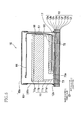
Fig. 5 is an elevational view in vertical cross section showing the ink-jet head; -
Fig. 6A is a partial cross-sectional view of the actuator unit, andFig. 6B is a partial plan view of the actuator unit; and -
Fig. 7 is a partial plan view of the actuator unit, showing an arrangement of a plurality of individual electrodes and dummy lands. - Hereinafter, there will be described an embodiment of the present invention by reference to the drawings.
- First, there will be explained, with reference to
Fig. 1 , an overall construction of an ink-jet printer including ink-jet heads 10 each as an embodiment of the present invention. - The
printer 1 includes a casing 1a having a rectangular parallelepiped shape. A sheet-discharge portion 31 is provided on a top plate of the casing 1a. An inner space of the casing 1a is divided into spaces A, B, C in order from an upper side thereof. In the spaces A, B is formed a sheet feeding path which is continuous to the sheet-discharge portion 31. In the space A, theprinter 1 performs feeding or conveying of a recording medium such as a sheet P and records or forms an image on the sheet P. In the space B, theprinter 1 performs an operation for supplying the sheet P. In the space C are accommodatedcartridges 40 each as an ink supply source. - In the space A, there are arranged the four ink-jet heads 10, a sheet-
feed unit 21 for feeding the sheet P, a guide unit (which will be described below) for guiding the sheet P, and so on. In an upper portion of the space A, there is disposed acontroller 1p configured to control operations of components of theprinter 1 to control an overall operation of theprinter 1. - In order to record an image on the sheet P on the basis of image data supplied from an external device, the
controller 1p controls: a preliminary operation for the recording; the supplying, feeding, and discharging of the sheet P; an ink ejection operation synchronized with the feeding of the sheet P; a maintenance operation for recovering or maintaining an ejection property; and so on. - The
controller 1p includes a Central Processing Unit (CPU), a Read Only Memory (ROM), a Random Access Memory (RAM) such as a nonvolatile RAM, an Application Specific Integrated Circuit (ASIC), an interface (I/F), an Input/Output Port (I/O), and so on. The ROM stores therein programs executed by the CPU, various fixed data, and so on. The RAM temporarily stores therein data (such as image data) required for the execution of the programs. The ASIC performs, e.g., rewriting and sorting of the image data, a signal processing, an image processing, and so on. The I/F transmits or receives data to or from the external device. The I/O inputs or outputs detection signals of various sensors. - Each of the
heads 10 is a line head having a generally rectangular parallelepiped shape elongated in a main scanning direction in which each head reciprocates. The four heads 10 are arranged at predetermined pitches in a sub-scanning direction and supported by the casing 1a via ahead frame 3. Eachhead 10 includes achannel unit 12, eight actuator units 17 (seeFig. 2 ), and areservoir unit 11. In the image recording, theheads 10 respectively eject inks of respective four colors, namely, black (K), magenta (M), cyan (C), and yellow (Y), from lower faces of therespective heads 10a (ejection faces 10a). The construction of eachhead 10 will be explained in greater detail below. - As shown in
Fig. 1 , the sheet-feed unit 21 includes (a)belt rollers 6, 7, (b) an endlesssheet feeding belt 8 wound around therollers 6, 7, (c) a nip roller 4 and apeeling plate 5 respectively disposed on opposite sides (outsides) of thesheet feeding belt 8, aplaten 9 disposed inside thesheet feeding belt 8, and so on. - The belt roller 7 is a drive roller which is rotated in a clockwise direction in
Fig. 1 by a sheet-feed motor, not shown. Thesheet feeding belt 8 runs or is circulated along bold arrow inFig. 1 in accordance with the rotation of the belt roller 7. Thebelt roller 6 is a driven roller which is rotated in the clockwise direction inFig. 1 in accordance with the circulation of thesheet feeding belt 8. The nip roller 4 is disposed so as to face thebelt roller 6 and press, onto an outercircumferential face 8a of thesheet feeding belt 8, the sheet P fed from an upstream guide portion which will be described below. The peelingplate 5 is disposed so as to face the belt roller 7 and peel the sheet P from the outercircumferential face 8a and guide the sheet P to a downstream guide portion which will be described below. Theplaten 9 is disposed so as to face the four heads 2 and support an upper portion of thesheet feeding belt 8 from an inside thereof. As a result, a space suitable for the image recording is formed between the outercircumferential face 8a and the ejection faces 10a of the respective heads 10. - The guide unit includes the upstream guide portion and the downstream guide portion disposed with the sheet-
feed unit 21 interposed therebetween. The upstream guide portion includesguides roller pair 26 and connects a sheet-supply unit 1b (which will be described below) and the sheet-feed unit 21 to each other. The downstream guide portion includesguides feed unit 21 and the sheet-discharge portion 31 to each other. - In the space B is disposed the sheet-
supply unit 1b including a sheet-supply tray 23 and a sheet-supply roller 25. The sheet-supply tray 23 is mountable on and removable from the casing 1 a. The sheet-supply tray 23 has a box-like shape opening upward so as to accommodate various sizes of sheets P. The sheet-supply roller 25 supplies an uppermost one of the sheets P in the sheet-supply tray 23 to the upstream guide portion. - As described above, in the spaces A, B is formed the sheet feeding path extending from the sheet-supply unit lb to the sheet-
discharge portion 31 via the sheet-feed unit 21. On the basis of a recording command, thecontroller 1p drives a plurality of motors such as a sheet-supply motor, not shown, for the sheet-supply roller 25, a sheet-feed motor, not shown, for the sheet-feed rollers of each of the upstream and downstream guide portions, the above-described sheet-feed motor, and the like. The sheet P supplied from the sheet-supply tray 23 is supplied to the sheet-feed unit 21 by the feed-roller pair 26. When the sheet P passes through positions just under theheads 10 in the sub-scanning direction, theheads 10 eject the inks of the respective four colors in order from the respective ejection faces 10a, to record a color image on the sheet P. The ink ejection is performed on the basis of a detection signal outputted from asheet sensor 32. The sheet P is then peeled by the peelingplate 5 and fed upward by the feed-roller pairs 28. The sheet P is then discharged onto the sheet-discharge portion 31 through anopening 3 0. - Here, the sub-scanning direction is a direction parallel to the sheet feeding direction in which the sheet P is fed by the sheet-
feed unit 21 and along a horizontal plane, and the main scanning direction is a direction perpendicular to the sub-scanning direction and along the horizontal plane. - In the space C, an ink unit 1c is disposed so as to be mountable on and removable from the casing 1a. The ink unit 1c includes a
cartridge tray 35 and the fourcartridges 40 accommodated in thetray 35 side by side. The inks stored in therespective cartridges 40 are supplied to therespective heads 10 via respective ink tubes, not shown. - There will be next explained the construction of each
head 10 with reference toFigs. 2-5 in detail. It is noted that, inFig. 3 ,pressure chambers 16 andapertures 15 are illustrated by solid lines for easier understanding purposes though these elements are located under theactuator units 17 and thus should be illustrated by broken lines. It is further noted that, since the fourheads 10 have the same construction, the following explanation will be given for one of theheads 10 for the sake of simplicity. - As shown in
Fig. 5 , thehead 10 is a laminar body in which thechannel unit 12, theactuator units 17, thereservoir unit 11, and a printedcircuit 64 are stacked or laminated on one another. Theactuator units 17, thereservoir unit 11, and the printedcircuit 64 are accommodated in a space defined by anupper face 12x of thechannel unit 12 and acover 65. In this space, Flexible Printed Circuits (FPCs) 50 electrically connect therespective actuator units 17 and the printedcircuit 64.Driver ICs 57 are respectively mounted on theFPCs 50. - As shown in
Fig. 5 , thecover 65 includes atop cover 65a and analuminum side cover 65a. Thecover 65 is a box opening downward and fixed to theupper face 12x of thechannel unit 12. Thedriver ICs 57 are held in contact with an inner face of theside cover 65a so as to be thermally connected to thecover 65b. It is noted that, in order for a reliable thermal connection, thedriver ICs 57 are urged toward theside cover 65a by anelastic member 58 such as a sponge fixed to a side face of thereservoir unit 11. - The
reservoir unit 11 is a laminar body constituted by fourmetal plates 11a-11d bonded to one another. In thereservoir unit 11 is formed an ink channel including areservoir 72 for string the ink. The ink channel has: one end connected to the correspondingcartridge 40 via the corresponding tube; and the other end connected to thechannel unit 12. As shown inFig. 5 , a projection and a recess are formed on and in a lower face of theplate 11d such that the recess forms a space between theplate 11d and theupper face 12x. Eachactuator unit 17 is fixed to theupper face 12x in the space, with a small clearance formed over the correspondingFPC 50. Theplate 11d has anink outlet channel 73 formed therein. Theink outlet channel 73 is opened in a distal end face of the projection formed on the lower face of theplate 11d, that is, theink outlet channel 73 is opened in a face of theplate 11d which is bonded to theupper face 12x. - The
channel unit 12 is a laminar body constituted by nine metalrectangular plates 12a-12i (seeFig. 4 ) having generally the same size and bonded to one another. As shown inFig. 2 ,openings 12y are formed in theupper face 12x of thechannel unit 12 so as to be respectively connected toopenings 73a of theink outlet channel 73. In thechannel unit 12, there are formed ink channels each from one of theopenings 12y to one ofejection openings 14a. As shown inFigs. 2 ,3 , and4 , the ink channels include (a)manifold channels 13 respectively having theopenings 12y at respective one ends, (b)sub-manifold channels 13a each branched from a corresponding one of themanifold channels 13, and (c) individual channels 14 (each as one example of a liquid channel) each extending from an outlet of a corresponding one of thesub-manifold channels 13a to a corresponding one of theejection openings 14a via a corresponding one of thepressure chambers 16. - As shown in
Fig. 4 , theindividual channel 14 is formed for each ejection opening 14a so as to have (a) anaperture 15 functioning as a restrictor for adjusting a channel resistance and (b) apressure chamber 16 opened in theupper face 12x. As shown inFig. 3 , eachpressure chamber 16 has a generally rhombic shape, and thepressure chambers 16 are arranged in theupper face 12x in matrix so as to form eight pressure chamber groups each having a generally trapezoid shape in plan view. Likewise, theejection openings 14a are arranged in theejection face 10a in matrix so as to form eight ejection opening groups each having a generally trapezoid shape in plan view. - As shown in
Fig. 2 , theactuator units 17 each has a trapezoid shape and are arranged on theupper face 12x in two arrays in a staggered configuration. As shown inFig. 3 , each of theactuator units 17 is disposed on an area corresponding to the trapezoid shape of a corresponding one of the pressure chamber groups (the ejection opening groups). - The
FPC 50 is provided for eachactuator unit 17. TheFPC 50 has a wire and a terminal corresponding to each electrode of theactuator unit 17. The wire is connected to an output terminal of thedriver IC 57. Thecontroller 1p (seeFig. 1 ) controls theFPC 50 to transmit data adjusted by the printedcircuit 64 to thedriver IC 57 and to transmit drive signals produced by thedriver IC 57 to each electrode of theactuator units 17. The drive signals are selectively applied to the electrodes. - There will be next explained a construction of each
actuator unit 17 with reference toFigs. 6A, 6B , and7 . It is noted that the following explanation will be given for oneactuator unit 17 for the sake of simplicity. - As shown in
Fig. 6A , theactuator unit 17 includes a laminar body constituted by threepiezoelectric layers piezoelectric layers piezoelectric layers piezoelectric layer 17a is polarized in a direction coinciding with a direction in which thepiezoelectric layers - The
piezoelectric layers actuator unit 17, in plan view, i.e., when seen in a direction perpendicular to a face 17a1 of thepiezoelectric layer 17a which is a face thereof on the other side of thepiezoelectric layer 17b. That is, theactuator unit 17 is disposed so as to face and lay across thepressure chambers 16 and such that thepiezoelectric layer 17c seals all thepressure chambers 16. In the present embodiment, thepiezoelectric layers - A multiplicity of
individual electrodes 18 are formed on the face l7a1 at positions respectively facing thepressure chambers 16. Acommon electrode 19 is formed between thepiezoelectric layer 17a and thepiezoelectric layer 17b. Ametal layer 20 is formed between thepiezoelectric layer 17b and thepiezoelectric layer 17c. No electrodes are formed on a lower face of thepiezoelectric layer 17c. Thecommon electrode 19 is formed on an entire upper face of thepiezoelectric layer 17b, and themetal layer 20 is formed on an entire upper face of thepiezoelectric layer 17c. Each of theseelectrodes 18, 19 (exceptlands 18c which will be described below) and themetal layer 20 is formed of gold (Au) and has a thickness of about 1 µm. It is noted that themetal layer 20 is connected to thecommon electrode 19 via a through hole at a corner portion of thetrapezoidal actuator unit 17 in plan view. Themetal layer 20 acts, together with thecommon electrode 19, as a constant potential electrode for all thepressure chambers 16 corresponding to theactuator unit 17. - Like the
pressure chambers 16, theindividual electrodes 18 are arranged in matrix so as to form a plurality of rows and columns. As shown inFig. 6B , each of theindividual electrodes 18 is constituted by amain portion 18a, an extended portion 18b1, a dummy extended portion 18b2, and theland 18c. Themain portion 18a has a generally rhombic shape and faces thecorresponding pressure chamber 16 in its entirety. The extended portion 18b1 extends from one of acute portions of themain portion 18a in an X direction (as one example of an extending direction) such that a distal end of the extended portion 18b1 does not face thepressure chamber 16 in plan view. Theland 18c is formed on the distal end of the extended portion 18b1 so as not to face thepressure chamber 16. The dummy extended portion 18b2 extends from the other of the acute portions of themain portion 18a in a Y direction (as one example of an opposite direction) such that a distal end of the extended portion 18b2 does not face thepressure chamber 16 in plan view like the extended portion 18b1. It is noted that the X direction and the Y direction are parallel and opposite to each other. - The
main portion 18a is geometrically similar to and one-size smaller than thepressure chamber 16 and included within thepressure chamber 16 in plan view. As shown inFig. 6B , themain portion 18a is elongated in the X direction. When theactuator unit 17 and thechannel unit 12 are arranged such that barycenters of themain portion 18a and thepressure chamber 16 coincide with each other, a distance D (about 64µm) between an edge of themain portion 18a and a wall defining thepressure chamber 16 is constant over the edge of themain portion 18a except areas in which the extended portion 18b1 and the dummy extended portion 18b2 extend. - Each of the extended portion 18b and the dummy extended portion 18b2 has a generally rectangular shape. A width Wb1 (about 100µm) of the extended portion 18b1 in a direction perpendicular to the X direction is the same as a width Wb2 of the dummy extended portion 18b2 and shorter than a width Wa of the
main portion 18a. A length Lb2 of the dummy extended portion 18b2 in the Y direction is about 80µm. - The
land 18c is formed of a conductive material such as silver palladium (AgPd), gold (Au), and silver (Ag). In the present embodiment, theland 18c is formed of the silver palladium (AgPd). Theland 18c has a circular cylindrical shape having a diameter of about 130µm. A distal end face (an upper face) of theland 18c is located at a position higher than the face 17a1 by about 10µm. Theland 18c is connected to a terminal of theFPC 50 via a bump, not shown, formed on the upper face of theland 18c. - The
piezoelectric layer 17a includes active portions each interposed by a corresponding one of theindividual electrodes 18 and thecommon electrode 19. When an electric field is applied to each active portion from an external device, the active portion is displaced in at least one of vibration modes d31, d33, d15 (in d31 in the present embodiment). Each of thepiezoelectric layers actuator unit 17 has a piezoelectric actuator of a unimorph type in which one active portion and two non-active portions are stacked on one another for eachpressure chamber 16. The piezoelectric actuators can be deformed independently of each other. When a drive voltage is applied to thelands 18c from theFPCs 50, the piezoelectric actuators are selectively deformed, thereby changing volume(s) of corresponding one or ones of thepressure chambers 16. As a result, an energy is applied to the ink in the pressure chamber(s) 16, and thereby an ink droplet is ejected from each of the corresponding ejection opening(s) 14a. - As shown in
Fig. 7 , on the face 17a1, theindividual electrodes 18 having the extended portions 18b1 extending in opposite directions are alternately arranged in the main scanning direction. In the case of theindividual electrode 18 indicated by "I" inFig. 7 and theindividual electrode 18 indicated by "II" inFig. 7 , a direction in which the extended portion 18b1 of theindividual electrode 18 indicated by "I" extends is an upward direction inFig. 7 , and a direction in which the extended portion 18b1 of theindividual electrode 18 indicated by "II" extends is a downward direction inFig. 7 . - In addition to the
lands 18c of the respectiveindividual electrodes 18, dummy lands 18d and common-electrode lands 18e are formed on the face 17a1. Each of the dummy lands 18d and the common-electrode lands 18e is formed of the same material as that of theland 18c and has the same shape and size as those of theland 18c. A bump, not shown, is formed on a distal end face of each of the dummy lands 18d and the common-electrode lands 18e. Each of the dummy lands 18d is disposed so as to be symmetrical with a corresponding one of thelands 18c with respect to a barycenter of a corresponding one of themain portions 18a, and the dummy lands 18d does not face any of thepressure chambers 16. That is, each of the dummy lands 18d is located on a downstream side of the dummy extended portion 18b2 in the direction in which the dummy extended portion 18b2 extends (i.e., the Y direction). Eachdummy land 18d is electrically insulated from the correspondingindividual electrode 18 and distant from a distal end of the corresponding dummy extended portion 18b2. As shown inFig. 3 , the common-electrode lands 18e are disposed on the face 17al at areas corresponding to upper and lower bases of the trapezoid shape of eachactuator unit 17. Each of the common-electrode lands 18e is connected to a corresponding one of theFPCs 50 via a bump so as to be always kept at ground potential. It is noted that each common-electrode land 18e and thecommon electrode 19 are connected via a through hole extending through thepiezoelectric layer 17a. - As shown in
Fig. 7 , eachmain portion 18a is surrounded by threelands 18c and threedummy lands 18d. In other words, eachmain portion 18a is disposed at a center of a hexagon whose vertexes are respectively constituted by threelands 18c and threedummy lands 18d. Eachland pressure chamber 16 and the same height from the face 17a1. According to this construction, in each of a case where theactuator unit 17 is fixed to thechannel unit 12 and a case where theFPC 50 is fixed to theactuator unit 17, a pressing force is uniformly applied to thelands entire actuator unit 17. - As described above, each of the
heads 10 as the present embodiment includes theindividual electrodes 18 whose directions in which the extended portions 18b1 extend are opposite to each other (seeFig. 7 ) among the plurality of theindividual electrodes 18 on thepiezoelectric layer 17a. In this construction, even where theindividual electrodes 18 have been moved or misaligned in the X direction or the opposite direction thereto (i.e., in the Y direction) relatively to thepressure chamber 16, since the dummy extended portions 18b2 are provided as shown inFig. 6B , large differences are not caused in a volume decrease rate of the active portions (eventually in ink ejection properties of the corresponding ejection opening 14a) among theindividual electrodes 18 whose directions in which the extended portions 18b1 extend are opposite to each other. Accordingly, it is possible to prevent a deterioration of a recording quality. - Further, the width Wb1 of the extended portion 18b1 is shorter than the width Wa of the
main portion 18a. Accordingly, it is possible to prevent a structural cross talk which is a phenomenon that the displacement of the active portion corresponding to theindividual electrode 18 affects another active portion(s) adjacent thereto. - Further, the width Wb2 of the dummy extended portion 18b2 is shorter than the width Wa of the
main portion 18a. This also achieves an effect for preventing the structural cross talk. - Further, the width Wb1 of the extended portion 18b1 and the width Wb2 of the dummy extended portion 18b2 are equal to each other. Accordingly, it is possible to decrease a difference in the volume decrease rate of the active portion between a case where the
individual electrode 18 has been misaligned in the X direction and a case where theindividual electrode 18 has been misaligned in the Y direction. - Further, the
main portion 18a has a shape similar to that of thepressure chamber 16, thereby efficiently changing a volume (capacity) of thepressure chamber 16. Further, themain portion 18a is smaller in size than thepressure chamber 16, thereby achieving the effect for preventing the structural cross talk. - Further, each of the
main portion 18a and thepressure chamber 16 is elongated in the X direction in plan view. Accordingly, even where theindividual electrodes 18 have been misaligned in the X direction or the Y direction, it is possible to suppress a variation of the volume decrease rate of the active portions. Further, the above-described construction allows high-density or high-populated arrangement of thepressure chambers 16 and theindividual electrodes 18. Further, a pressure wave propagated in thepressure chamber 16 along its longitudinal direction can be used to efficiently change the volume of thepressure chamber 16. - Further, the extended portion 18b1 and the dummy extended portion 18b2 extend respectively from opposite end portions of the
main portion 18a in its longitudinal direction (in the above-described embodiment, the two acute portions of themain portion 18a having the rhombic shape). As a result, theindividual electrodes 18 can be arranged in higher density. - Further, the
land 18c is disposed at the position not facing thepressure chamber 16 in plan view. Accordingly, a force applied to theland 18c when theland 18c and the terminal of theFPC 50 are bonded to each other is transmitted to a portion of the laminar body constituted by thepiezoelectric layers pressure chamber 16. As a result, it is possible to prevent a portion of the laminar body which faces thepressure chamber 16 from being broken. - Further, as shown in
Fig. 7 , the dummy lands 18d are formed on the face l7a1. As a result, when theland 18c and the terminal of theFPC 50 are bonded to each other, the force is applied not only to theland 18c but also to thedummy land 18d. Accordingly, the force is distributed, thereby making it possible to reliably prevent the breakage of the laminar body. - Further, the
dummy land 18d is distant from the dummy extended portion 18b2. As a result, when compared to a case where thedummy land 18d is connected to the dummy extended portion 18b2, the structural cross talk is suppressed. - In addition, the
dummy land 18d is disposed so as to be symmetric with theland 18c with respect to the barycenter of themain portion 18a. As a result, the force is uniformly distributed, thereby making it possible to prevent the breakage of the laminar body more reliably. - Further, the dummy extended portion 18b2 extends to a position not facing the
pressure chamber 16 in plan view (seeFig. 6B ). As a result, even where theindividual electrode 18 has been misaligned in the X direction, it is possible to suppress a reduction in the volume of the active portion. - Further, as shown in
Fig. 7 , theindividual electrodes 18 having the extended portions 18b1 extending in opposite directions are alternately arranged in the main scanning direction on the face 17a1. In other words, first individual electrodes and second individual electrodes each having the extended portion 18b1 whose extending direction is opposite to that of the extended portion 18b of each of the first individual electrodes are alternately arranged in the main scanning direction. Since thelands 18c are arranged in balance, the terminals of theFPCs 50 can also be arranged in balance. As a result, when theland 18c and the terminal of theFPC 50 are bonded to each other, it is possible to reliably prevent the breakage of the laminar body owing to the force applied to theland 18c. - While the embodiment of the present invention has been described above, it is to be understood that the invention is not limited to the details of the illustrated embodiment, but may be embodied with various changes and modifications, which may occur to those skilled in the art, without departing from the spirit and scope of the invention.
- Each of the actuator units may include any number of the piezoelectric layers.
- Each of the lands and the dummy lands may have any shape, size, position, and the like. For example, the planar shape of each of the lands and the dummy lands may be various shapes such as an oval shape or a polygon, e.g., a triangle, instead of a circle. Each pair of the land and the dummy land may be disposed at a position facing the corresponding pressure chamber in a direction perpendicular to the face of the piezoelectric layer. The dummy lands and the common-electrode lands may not be formed on the face of the piezoelectric layer.
- Each of the main portions and the common electrodes may also have any shape, size, number, position, and the like. For example, each main portion may have a size larger than the corresponding pressure chamber and may have a size not similar to the corresponding pressure chambers. Further, a single common electrode may be provided for each actuator unit.
- A planar shape of each of the main portions and the pressure chambers is not limited to the elongated shape elongated in a direction in which the corresponding extended portion extends. The planar shape is limited to the rhombic shape and may be an oval shape, a rectangular shape, a circle, a square, or the like. The main portions (and the pressure chambers) are not limited to be arranged in matrix in plan view and may be arranged in a row in one direction (e.g., in the main scanning direction).
- At least one of the extended portion and the dummy extended portion does not need to extend to the position not facing the corresponding pressure chamber in the direction perpendicular to the face of the piezoelectric layer. For example, where each dummy extended portion entirely faces the corresponding pressure chamber in plan view, the distance between the edge of the main portion and the wall defining the pressure chamber is constant except the extended portion and become narrower in the dummy extended portion in a direction opposite to the direction in which the extended portion extends. Also in this case, the structural cross talk can be reduced. Further, each of the extended portions and the dummy extended portions has any width and length (size). For example, a width of each extended portion and a width of each dummy extended portion may be different from each other. Further, each dummy extended portion may be connected to the corresponding dummy land.
- Portions of the main portion from which the extended portion and the dummy extended portion extend are not particularly limited. For example, in
Fig. 6B , the extended portion and the dummy extended portion may respectively extend from opposite end portions of themain portion 18a in a widthwise direction thereof (two obtuse portions of themain portion 18a) or from opposite sides of the rhombic shape of themain portion 18a. In each of these cases, it is possible to suppress the deterioration of the recording quality in the case where the individual electrode has been misaligned in the direction in which the extended portion extends or in the direction opposite thereto. - The individual electrodes may not be alternately arranged in one direction along the face of the piezoelectric layer as long as individual electrodes having the extended portions extending in opposite directions are provided on the face.
- The liquid ejection head according to the present invention is not limited to the printer and may be applied to liquid ejection apparatuses such as a facsimile machine and a copying machine. Further, the number of the liquid ejection heads applied to the liquid ejection apparatus is not limited to four and may be the number equal to or larger than one. Each liquid ejection head is not limited to the line type and may be a serial type. Further, each liquid ejection head according to the present invention may ej ect liquid other than the ink.
Claims (12)
- A liquid ejection head (10) comprising:a channel unit (12) having a plurality of pressure chambers (16), a plurality of ejection openings (14a), and a plurality of liquid channels (14) formed therein, the liquid channels respectively extending from the pressure chambers to the ejection openings; andan actuator unit (17) including a piezoelectric layer (17a) and a plurality of individual electrodes (18) formed on a face of the piezoelectric layer, the actuator unit being configured to apply a drive voltage to the individual electrodes to change volumes of the respective pressure chambers respectively corresponding to the individual electrodes,wherein each of the individual electrodes includes:a land (18c) to which the drive voltage is applied;a main portion (18a) disposed such that an entire area thereof is opposite to a corresponding one of the pressure chambers in a direction perpendicular to the face of the piezoelectric layer;an extended portion (18b1) extending, in an extending direction in which the extended portion extends, from the main portion toward the land along the face of the piezoelectric layer so as to connect the main portion and the land to each other; anda dummy extended portion (18b2) extending from the main portion along the face of the piezoelectric layer in an opposite direction opposite to the extending direction.
- The liquid ejection head according to claim 1, wherein the land is disposed on the face of the piezoelectric layer at a position not opposed to any of the pressure chambers in the direction perpendicular to the face of the piezoelectric layer.
- The liquid ejection head according to claim 1, wherein the dummy extended portion extends along the face of the piezoelectric layer in the opposite direction from the main portion to a position on the face of the piezoelectric layer, the position being not opposed to any of the pressure chambers in the direction perpendicular to the face of the piezoelectric layer.
- The liquid ejection head according to claim 1, wherein a length of the extended portion in a direction perpendicular to the extending direction is shorter than a length of the main portion in the direction perpendicular to the extending direction as seen in the direction perpendicular to the face of the piezoelectric layer.
- The liquid ejection head according to claim 1, wherein a length of the dummy extended portion in a direction perpendicular to the extending direction is shorter than a length of the main portion in the direction perpendicular to the extending direction as seen in the direction perpendicular to the face of the piezoelectric layer.
- The liquid ejection head according to claim 1, wherein a length of the dummy extended portion in a direction perpendicular to the extending direction is generally the same as a length of the extended portion in the direction perpendicular to the extending direction as seen in the direction perpendicular to the face of the piezoelectric layer.
- The liquid ejection head according to claim 1, wherein the main portion has a shape similar to that of the corresponding pressure chamber and has an area smaller than that of the corresponding pressure chamber, as seen in the direction perpendicular to the face of the piezoelectric layer.
- The liquid ejection head according to claim 1, wherein each of respective lengths of the main portion and the corresponding pressure chamber in the extending direction is longer than each of respective lengths of the main portion and the corresponding pressure chamber in a direction perpendicular to the extending direction as seen in the direction perpendicular to the face of the piezoelectric layer.
- The liquid ejection head according to claim 8, wherein the extended portion and the dummy extended portion extend respectively from opposite end portions of the main portion in a longitudinal direction thereof.
- The liquid ejection head according to claim 1, further comprising a plurality of dummy lands (18d) respectively corresponding to the individual electrodes,
wherein each of the dummy lands has a shape the same as that of the corresponding land, and
wherein each of the dummy lands is distant from the corresponding dummy extended portion in a direction in which the dummy extended portion extends. - The liquid ejection head according to claim 10, wherein, when the actuator unit and the channel unit are arranged such that barycenters of the main portion and the corresponding pressure chamber coincide with each other as seen in the direction perpendicular to the face of the piezoelectric layer, the dummy land corresponding to the main portion is disposed on the face of the piezoelectric layer at a position not opposed to any of the pressure chambers and at a position at which the dummy land is symmetrical with the corresponding land with respect to the barycenter of the main portion.
- The liquid ejection head according to claim 1,
wherein the individual electrodes includes a plurality of first individual electrodes and a plurality of second individual electrodes each having the extended portion whose extending direction is opposite to that of the extended portion of each of the first individual electrodes, and
wherein the first individual electrodes and the second individual electrodes are alternately arranged in a direction perpendicular to the extending direction.
Applications Claiming Priority (1)
| Application Number | Priority Date | Filing Date | Title |
|---|---|---|---|
| JP2010185996 | 2010-08-23 |
Publications (2)
| Publication Number | Publication Date |
|---|---|
| EP2422985A1 true EP2422985A1 (en) | 2012-02-29 |
| EP2422985B1 EP2422985B1 (en) | 2014-05-07 |
Family
ID=45023917
Family Applications (1)
| Application Number | Title | Priority Date | Filing Date |
|---|---|---|---|
| EP11002371.0A Active EP2422985B1 (en) | 2010-08-23 | 2011-03-22 | Liquid ejection head |
Country Status (3)
| Country | Link |
|---|---|
| US (1) | US8353580B2 (en) |
| EP (1) | EP2422985B1 (en) |
| JP (1) | JP5434932B2 (en) |
Cited By (1)
| Publication number | Priority date | Publication date | Assignee | Title |
|---|---|---|---|---|
| CN103963466A (en) * | 2013-02-01 | 2014-08-06 | 精工爱普生株式会社 | Liquid ejecting head, liquid ejecting apparatus and method for manufacturing liquid ejecting head |
Families Citing this family (2)
| Publication number | Priority date | Publication date | Assignee | Title |
|---|---|---|---|---|
| WO2013145259A1 (en) * | 2012-03-30 | 2013-10-03 | 京セラ株式会社 | Liquid-discharging head and recording device using same |
| JP6131526B2 (en) | 2012-04-02 | 2017-05-24 | ブラザー工業株式会社 | Liquid discharge head and liquid discharge apparatus |
Citations (5)
| Publication number | Priority date | Publication date | Assignee | Title |
|---|---|---|---|---|
| US20060061633A1 (en) * | 2004-09-17 | 2006-03-23 | Brother Kogyo Kabushiki Kaisha | Ink-jet head |
| US20070195131A1 (en) * | 2005-08-31 | 2007-08-23 | Brother Kogyo Kabushiki Kaisha | Liquid jetting head and method for producing the same |
| US20080030553A1 (en) * | 2006-08-01 | 2008-02-07 | Brother Kogyo Kabushiki Kaisha | Liquid droplet-jetting apparatus and method for producing liquid droplet-jetting apparatus |
| US20090002462A1 (en) * | 2007-06-29 | 2009-01-01 | Brother Kogyo Kabushiki Kaisha | Actuator unit and manufacturing method thereof, and liquid ejection head |
| EP2075133A2 (en) * | 2007-12-28 | 2009-07-01 | Brother Kogyo Kabushiki Kaisha | Liquid transporting apparatus and piezoelectric actuator |
Family Cites Families (12)
| Publication number | Priority date | Publication date | Assignee | Title |
|---|---|---|---|---|
| DE3342844A1 (en) * | 1983-11-26 | 1985-06-05 | Philips Patentverwaltung Gmbh, 2000 Hamburg | MICROPLANAR INK JET PRINT HEAD |
| JPH1095112A (en) | 1996-09-25 | 1998-04-14 | Seiko Epson Corp | Actuator for ink-jet printer |
| JPH1134323A (en) | 1997-07-17 | 1999-02-09 | Mita Ind Co Ltd | Ink-jet head |
| JP2002248765A (en) * | 2000-12-19 | 2002-09-03 | Fuji Xerox Co Ltd | Ink-jet recording head and ink-jet recording apparatus |
| JP2003211661A (en) | 2002-01-24 | 2003-07-29 | Brother Ind Ltd | Ink jet head |
| JP4526244B2 (en) * | 2003-06-30 | 2010-08-18 | ブラザー工業株式会社 | Ink jet head, ink jet printer, and method of manufacturing ink jet head |
| JP2006035500A (en) * | 2004-07-23 | 2006-02-09 | Fuji Photo Film Co Ltd | Liquid ejection head and driving method therefor, and image forming apparatus |
| JP4419754B2 (en) * | 2004-08-27 | 2010-02-24 | ブラザー工業株式会社 | Inkjet head |
| JP2006076196A (en) | 2004-09-10 | 2006-03-23 | Fuji Xerox Co Ltd | Inkjet recording head, inkjet recording device, and piezoelectric actuator characteristic adjusting method |
| JP5358868B2 (en) * | 2004-11-01 | 2013-12-04 | ブラザー工業株式会社 | Piezoelectric actuator, method of manufacturing piezoelectric actuator, liquid transfer device, and method of manufacturing liquid transfer device |
| JP2006306073A (en) * | 2005-03-30 | 2006-11-09 | Brother Ind Ltd | Liquid transporting apparatus, and manufacturing method for liquid transporting apparatus |
| JP5181914B2 (en) * | 2008-08-08 | 2013-04-10 | ブラザー工業株式会社 | Positioning method |
-
2011
- 2011-01-26 JP JP2011014229A patent/JP5434932B2/en active Active
- 2011-03-22 EP EP11002371.0A patent/EP2422985B1/en active Active
- 2011-03-25 US US13/072,058 patent/US8353580B2/en active Active
Patent Citations (5)
| Publication number | Priority date | Publication date | Assignee | Title |
|---|---|---|---|---|
| US20060061633A1 (en) * | 2004-09-17 | 2006-03-23 | Brother Kogyo Kabushiki Kaisha | Ink-jet head |
| US20070195131A1 (en) * | 2005-08-31 | 2007-08-23 | Brother Kogyo Kabushiki Kaisha | Liquid jetting head and method for producing the same |
| US20080030553A1 (en) * | 2006-08-01 | 2008-02-07 | Brother Kogyo Kabushiki Kaisha | Liquid droplet-jetting apparatus and method for producing liquid droplet-jetting apparatus |
| US20090002462A1 (en) * | 2007-06-29 | 2009-01-01 | Brother Kogyo Kabushiki Kaisha | Actuator unit and manufacturing method thereof, and liquid ejection head |
| EP2075133A2 (en) * | 2007-12-28 | 2009-07-01 | Brother Kogyo Kabushiki Kaisha | Liquid transporting apparatus and piezoelectric actuator |
Cited By (2)
| Publication number | Priority date | Publication date | Assignee | Title |
|---|---|---|---|---|
| CN103963466A (en) * | 2013-02-01 | 2014-08-06 | 精工爱普生株式会社 | Liquid ejecting head, liquid ejecting apparatus and method for manufacturing liquid ejecting head |
| CN103963466B (en) * | 2013-02-01 | 2017-04-12 | 精工爱普生株式会社 | Liquid ejecting head, liquid ejecting apparatus and method for manufacturing liquid ejecting head |
Also Published As
| Publication number | Publication date |
|---|---|
| JP5434932B2 (en) | 2014-03-05 |
| JP2012066565A (en) | 2012-04-05 |
| EP2422985B1 (en) | 2014-05-07 |
| US20120044302A1 (en) | 2012-02-23 |
| US8353580B2 (en) | 2013-01-15 |
Similar Documents
| Publication | Publication Date | Title |
|---|---|---|
| US7004565B2 (en) | Ink-jet head and ink-jet printer having the ink-jet head | |
| JP5637032B2 (en) | Liquid discharge head | |
| JP5051106B2 (en) | Droplet ejector | |
| JP4206775B2 (en) | Inkjet head | |
| US11569429B2 (en) | Liquid discharge head | |
| US6984027B2 (en) | Ink-jet head and ink-jet printer having ink-jet head | |
| US8353579B2 (en) | Droplet ejecting head capable of suppressing worsening of deformation efficiency of actuator | |
| JP4059168B2 (en) | Inkjet recording apparatus, inkjet recording method and program | |
| EP2422985B1 (en) | Liquid ejection head | |
| US8419148B2 (en) | Droplet ejecting device capable of increasing number of tones efficiently | |
| JP6131526B2 (en) | Liquid discharge head and liquid discharge apparatus | |
| JP2006168036A (en) | Inkjet recording device | |
| JP5637031B2 (en) | Liquid discharge head | |
| EP1336488B1 (en) | Ink-jet head and ink-jet printer having ink-jet head | |
| US11538978B2 (en) | Liquid discharge head | |
| JP5932490B2 (en) | Liquid discharge head and recording apparatus using the same | |
| JP4479732B2 (en) | Inkjet recording device | |
| US8353578B2 (en) | Piezoelectric actuator and liquid-droplet ejection head | |
| JP6134030B2 (en) | Liquid discharge head and recording apparatus using the same | |
| JP2003311955A (en) | Inkjet head and inkjet printer comprising it | |
| JP2022169337A (en) | Liquid discharge head | |
| JP2009154444A (en) | Recorder | |
| JP4337928B2 (en) | Ink jet head and ink jet printer provided with the same | |
| JP2009178895A (en) | Inkjet printer |
Legal Events
| Date | Code | Title | Description |
|---|---|---|---|
| AK | Designated contracting states |
Kind code of ref document: A1 Designated state(s): AL AT BE BG CH CY CZ DE DK EE ES FI FR GB GR HR HU IE IS IT LI LT LU LV MC MK MT NL NO PL PT RO RS SE SI SK SM TR |
|
| AX | Request for extension of the european patent |
Extension state: BA ME |
|
| PUAI | Public reference made under article 153(3) epc to a published international application that has entered the european phase |
Free format text: ORIGINAL CODE: 0009012 |
|
| 17P | Request for examination filed |
Effective date: 20120829 |
|
| GRAP | Despatch of communication of intention to grant a patent |
Free format text: ORIGINAL CODE: EPIDOSNIGR1 |
|
| INTG | Intention to grant announced |
Effective date: 20131216 |
|
| GRAS | Grant fee paid |
Free format text: ORIGINAL CODE: EPIDOSNIGR3 |
|
| GRAA | (expected) grant |
Free format text: ORIGINAL CODE: 0009210 |
|
| AK | Designated contracting states |
Kind code of ref document: B1 Designated state(s): AL AT BE BG CH CY CZ DE DK EE ES FI FR GB GR HR HU IE IS IT LI LT LU LV MC MK MT NL NO PL PT RO RS SE SI SK SM TR |
|
| REG | Reference to a national code |
Ref country code: GB Ref legal event code: FG4D |
|
| REG | Reference to a national code |
Ref country code: AT Ref legal event code: REF Ref document number: 666304 Country of ref document: AT Kind code of ref document: T Effective date: 20140515 |
|
| REG | Reference to a national code |
Ref country code: IE Ref legal event code: FG4D |
|
| REG | Reference to a national code |
Ref country code: DE Ref legal event code: R096 Ref document number: 602011006640 Country of ref document: DE Effective date: 20140618 |
|
| REG | Reference to a national code |
Ref country code: AT Ref legal event code: MK05 Ref document number: 666304 Country of ref document: AT Kind code of ref document: T Effective date: 20140507 |
|
| REG | Reference to a national code |
Ref country code: NL Ref legal event code: VDEP Effective date: 20140507 |
|
| REG | Reference to a national code |
Ref country code: LT Ref legal event code: MG4D |
|
| PG25 | Lapsed in a contracting state [announced via postgrant information from national office to epo] |
Ref country code: LT Free format text: LAPSE BECAUSE OF FAILURE TO SUBMIT A TRANSLATION OF THE DESCRIPTION OR TO PAY THE FEE WITHIN THE PRESCRIBED TIME-LIMIT Effective date: 20140507 Ref country code: GR Free format text: LAPSE BECAUSE OF FAILURE TO SUBMIT A TRANSLATION OF THE DESCRIPTION OR TO PAY THE FEE WITHIN THE PRESCRIBED TIME-LIMIT Effective date: 20140808 Ref country code: FI Free format text: LAPSE BECAUSE OF FAILURE TO SUBMIT A TRANSLATION OF THE DESCRIPTION OR TO PAY THE FEE WITHIN THE PRESCRIBED TIME-LIMIT Effective date: 20140507 Ref country code: IS Free format text: LAPSE BECAUSE OF FAILURE TO SUBMIT A TRANSLATION OF THE DESCRIPTION OR TO PAY THE FEE WITHIN THE PRESCRIBED TIME-LIMIT Effective date: 20140907 Ref country code: NO Free format text: LAPSE BECAUSE OF FAILURE TO SUBMIT A TRANSLATION OF THE DESCRIPTION OR TO PAY THE FEE WITHIN THE PRESCRIBED TIME-LIMIT Effective date: 20140807 Ref country code: CY Free format text: LAPSE BECAUSE OF FAILURE TO SUBMIT A TRANSLATION OF THE DESCRIPTION OR TO PAY THE FEE WITHIN THE PRESCRIBED TIME-LIMIT Effective date: 20140507 |
|
| PG25 | Lapsed in a contracting state [announced via postgrant information from national office to epo] |
Ref country code: SE Free format text: LAPSE BECAUSE OF FAILURE TO SUBMIT A TRANSLATION OF THE DESCRIPTION OR TO PAY THE FEE WITHIN THE PRESCRIBED TIME-LIMIT Effective date: 20140507 Ref country code: LV Free format text: LAPSE BECAUSE OF FAILURE TO SUBMIT A TRANSLATION OF THE DESCRIPTION OR TO PAY THE FEE WITHIN THE PRESCRIBED TIME-LIMIT Effective date: 20140507 Ref country code: ES Free format text: LAPSE BECAUSE OF FAILURE TO SUBMIT A TRANSLATION OF THE DESCRIPTION OR TO PAY THE FEE WITHIN THE PRESCRIBED TIME-LIMIT Effective date: 20140507 Ref country code: AT Free format text: LAPSE BECAUSE OF FAILURE TO SUBMIT A TRANSLATION OF THE DESCRIPTION OR TO PAY THE FEE WITHIN THE PRESCRIBED TIME-LIMIT Effective date: 20140507 Ref country code: HR Free format text: LAPSE BECAUSE OF FAILURE TO SUBMIT A TRANSLATION OF THE DESCRIPTION OR TO PAY THE FEE WITHIN THE PRESCRIBED TIME-LIMIT Effective date: 20140507 Ref country code: RS Free format text: LAPSE BECAUSE OF FAILURE TO SUBMIT A TRANSLATION OF THE DESCRIPTION OR TO PAY THE FEE WITHIN THE PRESCRIBED TIME-LIMIT Effective date: 20140507 Ref country code: PL Free format text: LAPSE BECAUSE OF FAILURE TO SUBMIT A TRANSLATION OF THE DESCRIPTION OR TO PAY THE FEE WITHIN THE PRESCRIBED TIME-LIMIT Effective date: 20140507 |
|
| PG25 | Lapsed in a contracting state [announced via postgrant information from national office to epo] |
Ref country code: PT Free format text: LAPSE BECAUSE OF FAILURE TO SUBMIT A TRANSLATION OF THE DESCRIPTION OR TO PAY THE FEE WITHIN THE PRESCRIBED TIME-LIMIT Effective date: 20140908 |
|
| PG25 | Lapsed in a contracting state [announced via postgrant information from national office to epo] |
Ref country code: CZ Free format text: LAPSE BECAUSE OF FAILURE TO SUBMIT A TRANSLATION OF THE DESCRIPTION OR TO PAY THE FEE WITHIN THE PRESCRIBED TIME-LIMIT Effective date: 20140507 Ref country code: BE Free format text: LAPSE BECAUSE OF FAILURE TO SUBMIT A TRANSLATION OF THE DESCRIPTION OR TO PAY THE FEE WITHIN THE PRESCRIBED TIME-LIMIT Effective date: 20140507 Ref country code: DK Free format text: LAPSE BECAUSE OF FAILURE TO SUBMIT A TRANSLATION OF THE DESCRIPTION OR TO PAY THE FEE WITHIN THE PRESCRIBED TIME-LIMIT Effective date: 20140507 Ref country code: EE Free format text: LAPSE BECAUSE OF FAILURE TO SUBMIT A TRANSLATION OF THE DESCRIPTION OR TO PAY THE FEE WITHIN THE PRESCRIBED TIME-LIMIT Effective date: 20140507 Ref country code: RO Free format text: LAPSE BECAUSE OF FAILURE TO SUBMIT A TRANSLATION OF THE DESCRIPTION OR TO PAY THE FEE WITHIN THE PRESCRIBED TIME-LIMIT Effective date: 20140507 Ref country code: SK Free format text: LAPSE BECAUSE OF FAILURE TO SUBMIT A TRANSLATION OF THE DESCRIPTION OR TO PAY THE FEE WITHIN THE PRESCRIBED TIME-LIMIT Effective date: 20140507 |
|
| REG | Reference to a national code |
Ref country code: DE Ref legal event code: R097 Ref document number: 602011006640 Country of ref document: DE |
|
| PG25 | Lapsed in a contracting state [announced via postgrant information from national office to epo] |
Ref country code: NL Free format text: LAPSE BECAUSE OF FAILURE TO SUBMIT A TRANSLATION OF THE DESCRIPTION OR TO PAY THE FEE WITHIN THE PRESCRIBED TIME-LIMIT Effective date: 20140507 |
|
| PLBE | No opposition filed within time limit |
Free format text: ORIGINAL CODE: 0009261 |
|
| STAA | Information on the status of an ep patent application or granted ep patent |
Free format text: STATUS: NO OPPOSITION FILED WITHIN TIME LIMIT |
|
| 26N | No opposition filed |
Effective date: 20150210 |
|
| PG25 | Lapsed in a contracting state [announced via postgrant information from national office to epo] |
Ref country code: IT Free format text: LAPSE BECAUSE OF FAILURE TO SUBMIT A TRANSLATION OF THE DESCRIPTION OR TO PAY THE FEE WITHIN THE PRESCRIBED TIME-LIMIT Effective date: 20140507 |
|
| REG | Reference to a national code |
Ref country code: DE Ref legal event code: R097 Ref document number: 602011006640 Country of ref document: DE Effective date: 20150210 |
|
| PG25 | Lapsed in a contracting state [announced via postgrant information from national office to epo] |
Ref country code: SI Free format text: LAPSE BECAUSE OF FAILURE TO SUBMIT A TRANSLATION OF THE DESCRIPTION OR TO PAY THE FEE WITHIN THE PRESCRIBED TIME-LIMIT Effective date: 20140507 |
|
| PG25 | Lapsed in a contracting state [announced via postgrant information from national office to epo] |
Ref country code: LU Free format text: LAPSE BECAUSE OF FAILURE TO SUBMIT A TRANSLATION OF THE DESCRIPTION OR TO PAY THE FEE WITHIN THE PRESCRIBED TIME-LIMIT Effective date: 20150322 Ref country code: MC Free format text: LAPSE BECAUSE OF FAILURE TO SUBMIT A TRANSLATION OF THE DESCRIPTION OR TO PAY THE FEE WITHIN THE PRESCRIBED TIME-LIMIT Effective date: 20140507 |
|
| REG | Reference to a national code |
Ref country code: CH Ref legal event code: PL |
|
| REG | Reference to a national code |
Ref country code: IE Ref legal event code: MM4A |
|
| PG25 | Lapsed in a contracting state [announced via postgrant information from national office to epo] |
Ref country code: IE Free format text: LAPSE BECAUSE OF NON-PAYMENT OF DUE FEES Effective date: 20150322 Ref country code: LI Free format text: LAPSE BECAUSE OF NON-PAYMENT OF DUE FEES Effective date: 20150331 Ref country code: CH Free format text: LAPSE BECAUSE OF NON-PAYMENT OF DUE FEES Effective date: 20150331 |
|
| REG | Reference to a national code |
Ref country code: FR Ref legal event code: PLFP Year of fee payment: 6 |
|
| PG25 | Lapsed in a contracting state [announced via postgrant information from national office to epo] |
Ref country code: MT Free format text: LAPSE BECAUSE OF FAILURE TO SUBMIT A TRANSLATION OF THE DESCRIPTION OR TO PAY THE FEE WITHIN THE PRESCRIBED TIME-LIMIT Effective date: 20140507 |
|
| REG | Reference to a national code |
Ref country code: FR Ref legal event code: PLFP Year of fee payment: 7 |
|
| PG25 | Lapsed in a contracting state [announced via postgrant information from national office to epo] |
Ref country code: BG Free format text: LAPSE BECAUSE OF FAILURE TO SUBMIT A TRANSLATION OF THE DESCRIPTION OR TO PAY THE FEE WITHIN THE PRESCRIBED TIME-LIMIT Effective date: 20140507 Ref country code: HU Free format text: LAPSE BECAUSE OF FAILURE TO SUBMIT A TRANSLATION OF THE DESCRIPTION OR TO PAY THE FEE WITHIN THE PRESCRIBED TIME-LIMIT; INVALID AB INITIO Effective date: 20110322 Ref country code: SM Free format text: LAPSE BECAUSE OF FAILURE TO SUBMIT A TRANSLATION OF THE DESCRIPTION OR TO PAY THE FEE WITHIN THE PRESCRIBED TIME-LIMIT Effective date: 20140507 |
|
| PG25 | Lapsed in a contracting state [announced via postgrant information from national office to epo] |
Ref country code: TR Free format text: LAPSE BECAUSE OF FAILURE TO SUBMIT A TRANSLATION OF THE DESCRIPTION OR TO PAY THE FEE WITHIN THE PRESCRIBED TIME-LIMIT Effective date: 20140507 |
|
| REG | Reference to a national code |
Ref country code: FR Ref legal event code: PLFP Year of fee payment: 8 |
|
| PG25 | Lapsed in a contracting state [announced via postgrant information from national office to epo] |
Ref country code: MK Free format text: LAPSE BECAUSE OF FAILURE TO SUBMIT A TRANSLATION OF THE DESCRIPTION OR TO PAY THE FEE WITHIN THE PRESCRIBED TIME-LIMIT Effective date: 20140507 |
|
| PG25 | Lapsed in a contracting state [announced via postgrant information from national office to epo] |
Ref country code: AL Free format text: LAPSE BECAUSE OF FAILURE TO SUBMIT A TRANSLATION OF THE DESCRIPTION OR TO PAY THE FEE WITHIN THE PRESCRIBED TIME-LIMIT Effective date: 20140507 |
|
| PGFP | Annual fee paid to national office [announced via postgrant information from national office to epo] |
Ref country code: FR Payment date: 20230209 Year of fee payment: 13 |
|
| PGFP | Annual fee paid to national office [announced via postgrant information from national office to epo] |
Ref country code: GB Payment date: 20230208 Year of fee payment: 13 Ref country code: DE Payment date: 20230210 Year of fee payment: 13 |
|
| P01 | Opt-out of the competence of the unified patent court (upc) registered |
Effective date: 20230529 |