EP2421269A2 - Method and apparatus for adjusting 3D video images - Google Patents
Method and apparatus for adjusting 3D video images Download PDFInfo
- Publication number
- EP2421269A2 EP2421269A2 EP11159844A EP11159844A EP2421269A2 EP 2421269 A2 EP2421269 A2 EP 2421269A2 EP 11159844 A EP11159844 A EP 11159844A EP 11159844 A EP11159844 A EP 11159844A EP 2421269 A2 EP2421269 A2 EP 2421269A2
- Authority
- EP
- European Patent Office
- Prior art keywords
- video
- image
- adjusting
- binocular parallax
- complexity
- Prior art date
- Legal status (The legal status is an assumption and is not a legal conclusion. Google has not performed a legal analysis and makes no representation as to the accuracy of the status listed.)
- Withdrawn
Links
Images


Classifications
-
- H—ELECTRICITY
- H04—ELECTRIC COMMUNICATION TECHNIQUE
- H04N—PICTORIAL COMMUNICATION, e.g. TELEVISION
- H04N19/00—Methods or arrangements for coding, decoding, compressing or decompressing digital video signals
- H04N19/50—Methods or arrangements for coding, decoding, compressing or decompressing digital video signals using predictive coding
- H04N19/597—Methods or arrangements for coding, decoding, compressing or decompressing digital video signals using predictive coding specially adapted for multi-view video sequence encoding
-
- G—PHYSICS
- G06—COMPUTING; CALCULATING OR COUNTING
- G06T—IMAGE DATA PROCESSING OR GENERATION, IN GENERAL
- G06T7/00—Image analysis
- G06T7/97—Determining parameters from multiple pictures
-
- H—ELECTRICITY
- H04—ELECTRIC COMMUNICATION TECHNIQUE
- H04N—PICTORIAL COMMUNICATION, e.g. TELEVISION
- H04N13/00—Stereoscopic video systems; Multi-view video systems; Details thereof
- H04N13/10—Processing, recording or transmission of stereoscopic or multi-view image signals
- H04N13/106—Processing image signals
- H04N13/128—Adjusting depth or disparity
-
- H—ELECTRICITY
- H04—ELECTRIC COMMUNICATION TECHNIQUE
- H04N—PICTORIAL COMMUNICATION, e.g. TELEVISION
- H04N13/00—Stereoscopic video systems; Multi-view video systems; Details thereof
- H04N13/10—Processing, recording or transmission of stereoscopic or multi-view image signals
- H04N13/106—Processing image signals
- H04N13/144—Processing image signals for flicker reduction
-
- G—PHYSICS
- G06—COMPUTING; CALCULATING OR COUNTING
- G06T—IMAGE DATA PROCESSING OR GENERATION, IN GENERAL
- G06T2207/00—Indexing scheme for image analysis or image enhancement
- G06T2207/10—Image acquisition modality
- G06T2207/10016—Video; Image sequence
- G06T2207/10021—Stereoscopic video; Stereoscopic image sequence
-
- G—PHYSICS
- G06—COMPUTING; CALCULATING OR COUNTING
- G06T—IMAGE DATA PROCESSING OR GENERATION, IN GENERAL
- G06T2207/00—Indexing scheme for image analysis or image enhancement
- G06T2207/20—Special algorithmic details
- G06T2207/20021—Dividing image into blocks, subimages or windows
-
- H—ELECTRICITY
- H04—ELECTRIC COMMUNICATION TECHNIQUE
- H04N—PICTORIAL COMMUNICATION, e.g. TELEVISION
- H04N13/00—Stereoscopic video systems; Multi-view video systems; Details thereof
- H04N13/30—Image reproducers
- H04N13/356—Image reproducers having separate monoscopic and stereoscopic modes
Definitions
- the present invention relates to 3D image processing technology, and in particular relates to a method and apparatus for adjusting 3D video images in order to prevent viewers from motion sickness.
- Binocular parallax helps to create depth perception for humans, and 3D displays employ the binocular parallax phenomenon for 3D viewing.
- Figs. 1A and 1B are diagrams illustrating a binocular parallax.
- the binocular parallax When human eyes focus on a point P2 of a screen, the binocular parallax is zero. However, when human eyes focus on a point P1 of the screen, the binocular parallax is positive (so-called positive parallax), and when human eyes focus on a point P3 of the screen, the binocular parallax is negative (so-called negative parallax).
- the positive and negative parallax can respectively create a concaved image and a protruding image in the human visual system.
- Fig. 2 is a diagram illustrating a 3D display technique.
- the left image (as shown in the bottom left part in Fig. 2 ) and the right image (as shown in bottom right part in Fig. 2 ) related to each other, are created based on an original 2D image (as shown in upper part in Fig. 2 ) and have basically identical image contents.
- some objects e.g., the location of triangular objects in the bottom part of Fig. 2
- moving the triangular object in the left image rightward from the cube and moving the triangular object in the right image leftward from the cube creates a negative parallax and makes a viewer feel that the triangular object is closer than the cube.
- a positive parallax can be achieved in an opposite manner.
- 3D display techniques allow users to have unique experiences, continuously viewing a 3D display may make a viewer feel sick due to motion sickness. Thus, having motion sickness may ruin the experience of watching a 3D video for users. Therefore, a new method for adjusting the images of a 3D video is needed.
- the present invention provides a method for adjusting 3D video images, which comprises the steps of: receiving a 3D video, wherein the 3D video comprises a plurality of frames, and each frame comprises a plurality of image blocks; calculating displacement of each image block based on the locations of the same image block in the different frames and calculating the image complexity of the 3D video based on the displacements of the image blocks in the frames; converting the 3D video into a 2D video and displaying the 2D video when the image complexity is greater than a predetermined value, and displaying the 3D video when the image complexity is lower than the predetermined value.
- the present invention also provides a method for adjusting 3D video images, which comprises the steps of : receiving a 3D video, wherein the 3D video comprises a plurality of frames, and each frame comprises a plurality of image blocks; obtaining a binocular parallax value between a left eye image and a right eye image which related to each other in the 3D video; calculating displacement of each image block based on the locations of the same image block in the different frames and calculating the image complexity of the 3D video based on the displacements of the image blocks of the frames; converting the 3D video into a 2D video and displaying the 2D video when the image complexity is greater than a predetermined value, and adjusting the definition of depth of each image block in each frame of the 2D video, and displaying the 3D video when the image complexity is lower than the predetermined value, and adjusting the binocular parallax of each image block of each frame of the 3D video according the image complexity of the 3D video.
- the present invention also provides an apparatus for adjusting 3D video images, which comprises an image receiving unit for receiving a 3D video, wherein the 3D video comprises a plurality of frames, and each frame comprises a plurality of image blocks; an image complexity calculating unit, coupled to the image receiving unit, for calculating displacement of each image block based on the locations of the same image block in the different frames and calculating the image complexity of the 3D video based on the displacements of the image blocks of the frames; a 2D display unit, coupled to the image complexity unit, for converting the 3D video into a 2D video and displaying the 2D video when the image complexity is greater than a predetermined value; and a 3D display unit, coupled to the image complexity unit, for displaying the 3D video when the image complexity is lower than the predetermined value.
- Figs. 1A and 1B are diagrams illustrating a binocular parallax.
- Fig. 2 is a diagram illustrating a 3D display technique.
- Fig. 3 is flowchart of the method for adjusting 3D video images according to an embodiment of the present invention.
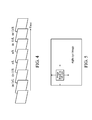
- Fig. 4 is the structure of the 3D video in an embodiment.
- Fig. 5 shows the left eye image n/L which is divided into image blocks with 3 ⁇ 3 pixels.
- Fig. 6A is an original diagram
- Fig. 6B is a z-plane diagram representing the original diagram by using gray levels 0 ⁇ 255.
- Fig. 7 is flowchart of a method for adjusting the definition of depth in a 2D video.
- Fig. 8A is a diagram showing a method of adjusting binocular parallax linearly inversely proportional to the image complexity.
- Fig. 8B is a diagram showing a method of adjusting binocular parallax nonlinearly inversely proportional to the image complexity where the straight line in Fig.8A is replaced by an S-curve.
- Fig. 9 is a schematic diagram of the apparatus 900 for adjusting the 3D video image according to an embodiment of the present invention.
- the present invention provides a new method for adjusting 3D video images, to enhance the 3D video experience of viewers.
- the purpose of the present invention is to lower the stereo effect created by the 3D video and convert the 3D video to a 2D video when the 3D video becomes excessively complicated, and enhance the stereo effect created by the 3D video image when the 3D video becomes excessively quiet.
- Fig. 3 is flowchart of the method for adjusting 3D video images according to an embodiment of the present invention.
- the method 300 for adjusting 3D video images comprises the steps of S310 ⁇ S350, which are described as follows:
- a 3D video is first received.
- Fig. 4 is the structure of the 3D video in an embodiment.
- the 3D video comprises a plurality of frames (e.g., (n-1)/L, (n-1)/R, n/L, n/R, (n+1)/L, (n+1) /R), wherein the symbols "/L” and "/R” respectively indicate a left eye image and right eye image which are related to each other.
- Each frame further comprises a plurality of image blocks, which will be described latter.
- step S320 a binocular parallax value of each image block of a frame based on the related left eye image (e.g., n/L) and right eye (e.g., n/R) image in the 3D video is obtained.
- an image correlation technique may be employed to obtain the binocular parallax.
- the left eye image n/L is divided into image blocks with 3 ⁇ 3 pixels, and each image block are then compared with the right eye image n/R (as shown in Fig. 5 ) by scanning the right eye image n/R. The scanning process stops when a same image block in the right eye image n/R is found.
- the displacement y of the image block between its original location and final location is called a "binocular parallax" of the image block.
- the binocular parallax y>0 it means that the image block is a positive parallax.
- the binocular parallax y ⁇ 0 it means that the image block is a negative parallax.
- Figs. 6A and 6B illustrate the image blocks and their binocular parallax.
- Fig. 6A is an original diagram
- Fig. 6B is a z-plane diagram representing the original diagram by using gray levels 0 ⁇ 255.
- the image blocks of the gray level 128 are zero parallax image blocks, while the image blocks of a gray level higher or lower than the gray level 128 are respectively negative parallax or positive parallax image blocks.
- step S330 the displacement of the image block based on the location of the same image block in the different frames and the image complexity of the 3D video based on the displacements of the image blocks of the frames are calculated.
- the image correlation technique can be employed to calculate the image blocks. Note that, to calculate the binocular parallax, the right and left eye images which are related to each other (for example, left eye image n/L and right eye image n/R) and usually displayed in order are compared with each other. However, to calculate the displacements of the image block (to estimate the change of the image block), the image blocks of two adjacent left images (or two adjacent right images) are compared with each other.
- the present invention will scan a next left eye image (n+1)_L.
- the location of the image blocks in different images are compared and the displacement m of the image blocks are calculated.
- the present invention should not be limited thereto.
- the present invention may further sum up or average all of the displacements to calculate the image complexity of the 3D video.
- Those skilled in the art may employ various algorithms to perform the calculating processes, which will not be further discussed here.
- the method of the present invention further compares the image complexity of the 3D video with a predetermined value to determine the manner of display of the 3D video.
- the method coverts the 3D video into a 2D video and displays the 2D video.
- the method displays the 3D video.
- the 3D video should be converted into a 2D video when the image content in the 3D video varies severely, and should keep displaying a 3D video when the image content in the 3D video is basically unchanged.
- the step of converting the 3D video into a 2D video further comprises zeroing the binocular parallax value of all of the image blocks in all of the frames of the 3D video. This means that the left eye image and right eye images will be adjusted to be identical to each other. Those skilled in the art can set the predetermined value to achieve their own customized video quality according to their own experiences or preferences.
- the converted 2D video in step S340 may be monotonous, and the converted and unconverted frames may not coordinate with each other. Therefore, the present invention further adjusts the definition of the depth of each image block in each frame of the 2D video.
- the binocular parallax producing depth perception is a 3D image display technique. Adjusting the definition of depth means respectively increasing or decreasing the definition of the foreground, middle ground or background of one image in different manners. Although the adjusting definition of depth may also create the stereo effect, it still belongs to a 2D display technique.
- Fig. 7 is flowchart of a method for adjusting the definition of depth in a 2D video.
- the method 700 for adjusting the definition of depth comprises: in step S702, averaging the definition of depth of all of the image blocks in each frame and obtaining an average binocular parallax y av ; in step S704, increasing the definition of depth of the image block which has a binocular parallax which is lower than the average binocular parallax y av ; and in step S706, decreasing the definition of depth of the image block which has a binocular parallax which is higher than the average binocular parallax y av .
- the averaged binocular parallax y av can be used to distinguish a foreground from a background of a frame.
- the definition of the foreground may be sharpening, and through step S706, the background may be blurred so that a 2D video having a clear foreground and background can be viewed.
- the method of the present invention can further display the 3D video in a manner different than that in prior art.
- the present invention further adjusts the binocular parallax of each of the image blocks of each frame of the 3D video according the image complexity of the 3D video, where the binocular parallax is adjusted inversely proportional to the image complexity of the 3D video.
- Fig. 8A is a diagram showing a method of adjusting binocular parallax linearly inversely proportional to the image complexity
- Fig. 8B is a diagram showing a method of adjusting binocular parallax nonlinearly inversely proportional to the image complexity where the straight line in Fig. 8A is replaced by an S-curve.
- step S350 is to dynamically adjust the depth sense created by the 3D video. In other words, when the image becomes excessively complicated, the present invention will ease the feeling of motion sickness by viewers by lowering the stereo sense created by the image and when the image becomes excessively quiet, the present invention will enhance the stereo sense.
- Fig. 9 is a schematic diagram of the apparatus 900 for adjusting the 3D video image according to an embodiment of the present invention.
- the apparatus of the present invention 900 comprises: an image receiving unit 910 for receiving a 3D video, wherein the 3D video comprises a plurality of frames, and each frame comprises a plurality of image blocks; an image complexity calculating unit 920, coupled to the image receiving unit 910, for calculating displacement of each image block based on the locations of the same image block in the different frames; calculating the image complexity of the 3D video based on the displacements of the image blocks of the frames; a 2D display unit 930, coupled to the image complexity unit 920, for converting the 3D video into a 2D video and displaying the 2D video when the image complexity is greater than a predetermined value; and a 3D display unit 940, coupled to the image complexity unit 920, for displaying the 3D video when the image
Abstract
Description
- This Non-provisional application claims priority under 35 U.S.C. §119(a) on Patent Application No(s).
99127261 - The present invention relates to 3D image processing technology, and in particular relates to a method and apparatus for adjusting 3D video images in order to prevent viewers from motion sickness.
- Binocular parallax helps to create depth perception for humans, and 3D displays employ the binocular parallax phenomenon for 3D viewing.
-
Figs. 1A and1B are diagrams illustrating a binocular parallax. When human eyes focus on a point P2 of a screen, the binocular parallax is zero. However, when human eyes focus on a point P1 of the screen, the binocular parallax is positive (so-called positive parallax), and when human eyes focus on a point P3 of the screen, the binocular parallax is negative (so-called negative parallax). The positive and negative parallax can respectively create a concaved image and a protruding image in the human visual system. -
Fig. 2 is a diagram illustrating a 3D display technique. For the current 3D display technique, the left image (as shown in the bottom left part inFig. 2 ) and the right image (as shown in bottom right part inFig. 2 ) related to each other, are created based on an original 2D image (as shown in upper part inFig. 2 ) and have basically identical image contents. However, some objects (e.g., the location of triangular objects in the bottom part ofFig. 2 ) are different from that in the top part ofFig. 2 . InFig. 2 , moving the triangular object in the left image rightward from the cube and moving the triangular object in the right image leftward from the cube creates a negative parallax and makes a viewer feel that the triangular object is closer than the cube. A positive parallax can be achieved in an opposite manner. - Although 3D display techniques allow users to have unique experiences, continuously viewing a 3D display may make a viewer feel sick due to motion sickness. Thus, having motion sickness may ruin the experience of watching a 3D video for users. Therefore, a new method for adjusting the images of a 3D video is needed.
- The present invention provides a method for adjusting 3D video images, which comprises the steps of: receiving a 3D video, wherein the 3D video comprises a plurality of frames, and each frame comprises a plurality of image blocks; calculating displacement of each image block based on the locations of the same image block in the different frames and calculating the image complexity of the 3D video based on the displacements of the image blocks in the frames; converting the 3D video into a 2D video and displaying the 2D video when the image complexity is greater than a predetermined value, and displaying the 3D video when the image complexity is lower than the predetermined value.
- The present invention also provides a method for adjusting 3D video images, which comprises the steps of : receiving a 3D video, wherein the 3D video comprises a plurality of frames, and each frame comprises a plurality of image blocks; obtaining a binocular parallax value between a left eye image and a right eye image which related to each other in the 3D video; calculating displacement of each image block based on the locations of the same image block in the different frames and calculating the image complexity of the 3D video based on the displacements of the image blocks of the frames; converting the 3D video into a 2D video and displaying the 2D video when the image complexity is greater than a predetermined value, and adjusting the definition of depth of each image block in each frame of the 2D video, and displaying the 3D video when the image complexity is lower than the predetermined value, and adjusting the binocular parallax of each image block of each frame of the 3D video according the image complexity of the 3D video.
- The present invention also provides an apparatus for adjusting 3D video images, which comprises an image receiving unit for receiving a 3D video, wherein the 3D video comprises a plurality of frames, and each frame comprises a plurality of image blocks; an image complexity calculating unit, coupled to the image receiving unit, for calculating displacement of each image block based on the locations of the same image block in the different frames and calculating the image complexity of the 3D video based on the displacements of the image blocks of the frames; a 2D display unit, coupled to the image complexity unit, for converting the 3D video into a 2D video and displaying the 2D video when the image complexity is greater than a predetermined value; and a 3D display unit, coupled to the image complexity unit, for displaying the 3D video when the image complexity is lower than the predetermined value.
- A detailed description is given in the following embodiments with reference to the accompanying drawings.
- The present invention can be more fully understood by reading the subsequent detailed description and examples with references made to the accompanying drawings, wherein:
-
Figs. 1A and1B are diagrams illustrating a binocular parallax. -
Fig. 2 is a diagram illustrating a 3D display technique. -
Fig. 3 is flowchart of the method for adjusting 3D video images according to an embodiment of the present invention. -
Fig. 4 is the structure of the 3D video in an embodiment. -
Fig. 5 shows the left eye image n/L which is divided into image blocks with 3×3 pixels. -
Fig. 6A is an original diagram, whileFig. 6B is a z-plane diagram representing the original diagram by usinggray levels 0~255. -
Fig. 7 is flowchart of a method for adjusting the definition of depth in a 2D video. -
Fig. 8A is a diagram showing a method of adjusting binocular parallax linearly inversely proportional to the image complexity. -
Fig. 8B is a diagram showing a method of adjusting binocular parallax nonlinearly inversely proportional to the image complexity where the straight line inFig.8A is replaced by an S-curve. -
Fig. 9 is a schematic diagram of theapparatus 900 for adjusting the 3D video image according to an embodiment of the present invention. - The following description is of the best-contemplated mode of carrying out the invention. This description is made for the purpose of illustrating the general principles of the invention and should not be taken in a limiting sense. The scope of the invention is best determined by reference to the appended claims.
- The present invention provides a new method for adjusting 3D video images, to enhance the 3D video experience of viewers. The purpose of the present invention is to lower the stereo effect created by the 3D video and convert the 3D video to a 2D video when the 3D video becomes excessively complicated, and enhance the stereo effect created by the 3D video image when the 3D video becomes excessively quiet.
-
Fig. 3 is flowchart of the method for adjusting 3D video images according to an embodiment of the present invention. The method 300 for adjusting 3D video images comprises the steps of S310∼S350, which are described as follows: - In step S310, a 3D video is first received.
Fig. 4 is the structure of the 3D video in an embodiment. The 3D video comprises a plurality of frames (e.g., (n-1)/L, (n-1)/R, n/L, n/R, (n+1)/L, (n+1) /R), wherein the symbols "/L" and "/R" respectively indicate a left eye image and right eye image which are related to each other. Each frame further comprises a plurality of image blocks, which will be described latter. - In step S320, a binocular parallax value of each image block of a frame based on the related left eye image (e.g., n/L) and right eye (e.g., n/R) image in the 3D video is obtained. In an embodiment, an image correlation technique may be employed to obtain the binocular parallax. For example, the left eye image n/L is divided into image blocks with 3×3 pixels, and each image block are then compared with the right eye image n/R (as shown in
Fig. 5 ) by scanning the right eye image n/R. The scanning process stops when a same image block in the right eye image n/R is found. When scanning, the displacement y of the image block between its original location and final location is called a "binocular parallax" of the image block. In this embodiment, when the binocular parallax y=0, it means that the image block is a zero parallax. When the binocular parallax y>0, it means that the image block is a positive parallax. When the binocular parallax y<0, it means that the image block is a negative parallax.Figs. 6A and6B illustrate the image blocks and their binocular parallax.Fig. 6A is an original diagram, whileFig. 6B is a z-plane diagram representing the original diagram by usinggray levels 0~255. The image blocks of thegray level 128 are zero parallax image blocks, while the image blocks of a gray level higher or lower than thegray level 128 are respectively negative parallax or positive parallax image blocks. - In step S330, the displacement of the image block based on the location of the same image block in the different frames and the image complexity of the 3D video based on the displacements of the image blocks of the frames are calculated. In an embodiment, the image correlation technique can be employed to calculate the image blocks. Note that, to calculate the binocular parallax, the right and left eye images which are related to each other (for example, left eye image n/L and right eye image n/R) and usually displayed in order are compared with each other. However, to calculate the displacements of the image block (to estimate the change of the image block), the image blocks of two adjacent left images (or two adjacent right images) are compared with each other. For example, to find the image block which is the same as the image block of the left eye image n/L, the present invention will scan a next left eye image (n+1)_L. When finding a same (or similar) image block in the next left eye image (n+1)_L, the location of the image blocks in different images are compared and the displacement m of the image blocks are calculated. Note that the present invention should not be limited thereto. After obtaining the displacements of all of the image blocks of a 3D video, the present invention may further sum up or average all of the displacements to calculate the image complexity of the 3D video. Those skilled in the art may employ various algorithms to perform the calculating processes, which will not be further discussed here.
- Then, the method of the present invention further compares the image complexity of the 3D video with a predetermined value to determine the manner of display of the 3D video. In step S340, when the image complexity is greater than the predetermined value, the method coverts the 3D video into a 2D video and displays the 2D video. In step S350, when the image complexity is lower than the predetermined value, the method displays the 3D video. Specifically, the 3D video should be converted into a 2D video when the image content in the 3D video varies severely, and should keep displaying a 3D video when the image content in the 3D video is basically unchanged. The step of converting the 3D video into a 2D video, for example, further comprises zeroing the binocular parallax value of all of the image blocks in all of the frames of the 3D video. This means that the left eye image and right eye images will be adjusted to be identical to each other. Those skilled in the art can set the predetermined value to achieve their own customized video quality according to their own experiences or preferences.
- However, the converted 2D video in step S340 may be monotonous, and the converted and unconverted frames may not coordinate with each other. Therefore, the present invention further adjusts the definition of the depth of each image block in each frame of the 2D video. Note that the binocular parallax producing depth perception is a 3D image display technique. Adjusting the definition of depth means respectively increasing or decreasing the definition of the foreground, middle ground or background of one image in different manners. Although the adjusting definition of depth may also create the stereo effect, it still belongs to a 2D display technique.
-
Fig. 7 is flowchart of a method for adjusting the definition of depth in a 2D video. The method 700 for adjusting the definition of depth comprises: in step S702, averaging the definition of depth of all of the image blocks in each frame and obtaining an average binocular parallax yav; in step S704, increasing the definition of depth of the image block which has a binocular parallax which is lower than the average binocular parallax yav; and in step S706, decreasing the definition of depth of the image block which has a binocular parallax which is higher than the average binocular parallax yav. The averaged binocular parallax yav can be used to distinguish a foreground from a background of a frame. Through step S704, the definition of the foreground may be sharpening, and through step S706, the background may be blurred so that a 2D video having a clear foreground and background can be viewed. - In step S350, the method of the present invention can further display the 3D video in a manner different than that in prior art. The present invention further adjusts the binocular parallax of each of the image blocks of each frame of the 3D video according the image complexity of the 3D video, where the binocular parallax is adjusted inversely proportional to the image complexity of the 3D video.
Fig. 8A is a diagram showing a method of adjusting binocular parallax linearly inversely proportional to the image complexity, whileFig. 8B is a diagram showing a method of adjusting binocular parallax nonlinearly inversely proportional to the image complexity where the straight line inFig. 8A is replaced by an S-curve. In these two methods, when the image complexity of an image is higher than a predetermined value (right sides of the point C inFigs. 8A and 8B ), the positive parallax and the negative parallax of the image are both decreased. When the image complexity of an image is lower than a predetermined value (left sides of the point C inFigs. 8A and 8B ), the positive parallax and the negative parallax of the image are both increased. The purpose of step S350 is to dynamically adjust the depth sense created by the 3D video. In other words, when the image becomes excessively complicated, the present invention will ease the feeling of motion sickness by viewers by lowering the stereo sense created by the image and when the image becomes excessively quiet, the present invention will enhance the stereo sense. Note that, when the present invention detects that the image complexity has exceeded a maximum value (point D inFigs 8A and 8B ), the binocular parallax of both the left and right eye images will be zeroed, which was discussed previously. Those skilled in the art may employ proper algorithms to adjust the binocular parallax of the image block in the 3D video, and the present invention is not limited thereto. - In addition to the method for adjusting 3D video images, the present invention further provides an apparatus for adjusting the 3D video image.
Fig. 9 is a schematic diagram of theapparatus 900 for adjusting the 3D video image according to an embodiment of the present invention. The apparatus of thepresent invention 900 comprises: animage receiving unit 910 for receiving a 3D video, wherein the 3D video comprises a plurality of frames, and each frame comprises a plurality of image blocks; an imagecomplexity calculating unit 920, coupled to theimage receiving unit 910, for calculating displacement of each image block based on the locations of the same image block in the different frames; calculating the image complexity of the 3D video based on the displacements of the image blocks of the frames; a2D display unit 930, coupled to theimage complexity unit 920, for converting the 3D video into a 2D video and displaying the 2D video when the image complexity is greater than a predetermined value; and a3D display unit 940, coupled to theimage complexity unit 920, for displaying the 3D video when the image complexity is lower than the predetermined value. Theapparatus 900 for adjusting 3D video images of the present invention can perform the aforementioned method for adjusting 3D video images, and will not be further discussed for brevity. - While the invention has been described by way of example and in terms of the preferred embodiments, it is to be understood that the invention is not limited to the disclosed embodiments. To the contrary, it is intended to cover various modifications and similar arrangements (as would be apparent to those skilled in the art). Therefore, the scope of the appended claims should be accorded the broadest interpretation so as to encompass all such modifications and similar arrangements.
Claims (14)
- A method for adjusting 3D video images, comprising the steps of:receiving a 3D video, wherein the 3D video comprises a plurality of frames, and each frame comprises a plurality of image blocks;calculating displacement of each image block based on the locations of the same image block in the different frames and calculating the image complexity of the 3D video based on the displacements of the image blocks in the frames;converting the 3D video into a 2D video and displaying the 2D video when the image complexity is greater than a predetermined value, anddisplaying the 3D video when the image complexity is lower than the predetermined value.
- The method for adjusting 3D video images as claimed in claim 1 further comprises:obtaining a binocular parallax value between a left eye image and a right eye image which is related to each other in the 3D video.
- The method for adjusting 3D video images as claimed in claim 2,
wherein the step of converting the 3D video into the 2D video further comprises:zeroing the binocular parallax value of all of the image blocks in all of the frames of the 3D video. - The method for adjusting 3D video images as claimed in claim 3,
wherein the step of displaying the 2D video further comprises:adjusting the definition of depth of each image block in each frame of the 2D video. - The method for adjusting 3D video images as claimed in claim 4,
wherein the step of adjusting the definition of depth of each image block in each frame of the 2D video further comprises:averaging the definition of depth of all of the image blocks in each frame and obtaining an average binocular parallax;increasing the definition of depth of the image block which has a binocular parallax which is lower than the average binocular parallax; anddecreasing the definition of depth of the image block which has a binocular parallax which is higher than the average binocular parallax. - The method for adjusting 3D video images as claimed in claim 2,
wherein the step of displaying the 3D video further comprises:adjusting the binocular parallax of each image block of each frame of the 3D video according the image complexity of the 3D video. - A method for adjusting 3D video images, comprising the steps of:receiving a 3D video, wherein the 3D video comprises a plurality of frames, and each frame comprises a plurality of image blocks;obtaining a binocular parallax value between a left eye image and a right eye image which related to each other in the 3D video;calculating displacement of each image block based on the locations of the same image block in the different frames and calculating the image complexity of the 3D video based on the displacements of the image blocks of the frames;converting the 3D video into a 2D video and displaying the 2D video when the image complexity is greater than a predetermined value, and adjusting the definition of depth of each image block in each frame of the 2D video, anddisplaying the 3D video when the image complexity is lower than the predetermined value, and adjusting the binocular parallax of each image block of each frame of the 3D video according the image complexity of the 3D video.
- The method for adjusting 3D video images as claimed in claim 7,
wherein the step of adjusting the definition of depth of all of the image blocks in all of the frames of the 2D video further comprises:averaging the definition of depth of all of the image blocks in each frame and obtaining an average binocular parallax;increasing the definition of depth of the image block which has a binocular parallax which is lower than the average binocular parallax; anddecreasing the definition of depth of the image block which has a binocular parallax which is higher than the average binocular parallax. - An apparatus for adjusting 3D video images, comprising:an image receiving unit for receiving a 3D video, wherein the 3D video comprises a plurality of frames, and each frame comprises a plurality of image blocks;an image complexity calculating unit, coupled to the image receiving unit, for calculating displacement of each image block based on the locations of the same image block in the different frames and calculating the image complexity of the 3D video based on the displacements of the image blocks of the frames;a 2D display unit, coupled to the image complexity unit, for converting the 3D video into a 2D video and displaying the 2D video when the image complexity is greater than a predetermined value; anda 3D display unit, coupled to the image complexity unit, for displaying the 3D video when the image complexity is lower than the predetermined value.
- The apparatus for adjusting 3D video images as claimed in claim 9,
wherein the image complexity calculating unit further obtains a binocular parallax value between a left eye image and a right eye image which are related to each other in the 3D video. - The apparatus for adjusting 3D video images as claimed in claim 10, wherein the 2D display unit further zeros the binocular parallax value of all of the image blocks in all of the frames of the 3D video.
- The apparatus for adjusting 3D video images as claimed in claim 11, wherein the 2D display unit adjusts the definition of depth of each image block in each frame of the 2D video.
- The apparatus for adjusting 3D video images as claimed in claim 12, wherein the 2D display unit further:averages the definition of depth of all of the image blocks in each frame to obtain an average binocular parallax;increases the definition of depth of the image block which has a binocular parallax which is lower than the average binocular parallax; anddecreases the definition of depth of the image block which has a binocular parallax which is higher than the average binocular parallax.
- The apparatus for adjusting 3D video images as claimed in claim 12, wherein the 3D display unit further adjusts the binocular parallax of each image block of each frame of the 3D video according the image complexity of the 3D video.
Applications Claiming Priority (1)
| Application Number | Priority Date | Filing Date | Title |
|---|---|---|---|
| TW099127261A TWI436636B (en) | 2010-08-16 | 2010-08-16 | Method and apparatus for adjusting three dimension video image |
Publications (2)
| Publication Number | Publication Date |
|---|---|
| EP2421269A2 true EP2421269A2 (en) | 2012-02-22 |
| EP2421269A3 EP2421269A3 (en) | 2015-09-09 |
Family
ID=44839447
Family Applications (1)
| Application Number | Title | Priority Date | Filing Date |
|---|---|---|---|
| EP11159844.7A Withdrawn EP2421269A3 (en) | 2010-08-16 | 2011-03-25 | Method and apparatus for adjusting 3D video images |
Country Status (3)
| Country | Link |
|---|---|
| US (1) | US20120038743A1 (en) |
| EP (1) | EP2421269A3 (en) |
| TW (1) | TWI436636B (en) |
Cited By (2)
| Publication number | Priority date | Publication date | Assignee | Title |
|---|---|---|---|---|
| US9628770B2 (en) | 2012-06-14 | 2017-04-18 | Blackberry Limited | System and method for stereoscopic 3-D rendering |
| EP2675172B1 (en) * | 2012-06-14 | 2020-06-10 | BlackBerry Limited | System and method for stereoscopic 3-d rendering |
Families Citing this family (3)
| Publication number | Priority date | Publication date | Assignee | Title |
|---|---|---|---|---|
| US8879826B2 (en) * | 2011-07-05 | 2014-11-04 | Texas Instruments Incorporated | Method, system and computer program product for switching between 2D and 3D coding of a video sequence of images |
| JP2013150249A (en) * | 2012-01-23 | 2013-08-01 | Sony Corp | Image processing device, image processing method and program |
| US9118911B2 (en) | 2013-02-07 | 2015-08-25 | Delphi Technologies, Inc. | Variable disparity three-dimensional (3D) display system and method of operating the same |
Family Cites Families (3)
| Publication number | Priority date | Publication date | Assignee | Title |
|---|---|---|---|---|
| EP0641132B1 (en) * | 1993-08-26 | 1999-04-14 | Matsushita Electric Industrial Co., Ltd. | Stereoscopic image pickup apparatus |
| JP3703232B2 (en) * | 1996-03-12 | 2005-10-05 | キヤノン株式会社 | Data communication device |
| JP4149037B2 (en) * | 1998-06-04 | 2008-09-10 | オリンパス株式会社 | Video system |
-
2010
- 2010-08-16 TW TW099127261A patent/TWI436636B/en active
-
2011
- 2011-03-14 US US13/047,580 patent/US20120038743A1/en not_active Abandoned
- 2011-03-25 EP EP11159844.7A patent/EP2421269A3/en not_active Withdrawn
Non-Patent Citations (1)
| Title |
|---|
| None |
Cited By (2)
| Publication number | Priority date | Publication date | Assignee | Title |
|---|---|---|---|---|
| US9628770B2 (en) | 2012-06-14 | 2017-04-18 | Blackberry Limited | System and method for stereoscopic 3-D rendering |
| EP2675172B1 (en) * | 2012-06-14 | 2020-06-10 | BlackBerry Limited | System and method for stereoscopic 3-d rendering |
Also Published As
| Publication number | Publication date |
|---|---|
| TW201210310A (en) | 2012-03-01 |
| TWI436636B (en) | 2014-05-01 |
| EP2421269A3 (en) | 2015-09-09 |
| US20120038743A1 (en) | 2012-02-16 |
Similar Documents
| Publication | Publication Date | Title |
|---|---|---|
| US9832445B2 (en) | Stereoscopic image display system, disparity conversion device, disparity conversion method, and program | |
| US10115207B2 (en) | Stereoscopic image processing method and apparatus thereof | |
| WO2011052389A1 (en) | Image processing device and image processing method | |
| WO2014083949A1 (en) | Stereoscopic image processing device, stereoscopic image processing method, and program | |
| US20140333739A1 (en) | 3d image display device and method | |
| WO2011148921A1 (en) | Image processor, image display apparatus, and imaging device | |
| Jung et al. | Visual comfort improvement in stereoscopic 3D displays using perceptually plausible assessment metric of visual comfort | |
| EP2611173A1 (en) | Image processing device, image processing method, and program | |
| EP2421269A2 (en) | Method and apparatus for adjusting 3D video images | |
| US20120327077A1 (en) | Apparatus for rendering 3d images | |
| US20130027391A1 (en) | Stereoscopic image system | |
| US20170309055A1 (en) | Adjusting parallax of three-dimensional display material | |
| US20120121163A1 (en) | 3d display apparatus and method for extracting depth of 3d image thereof | |
| CN106559662B (en) | Multi-view image display apparatus and control method thereof | |
| KR20130094905A (en) | Display apparatus and method for adjusting three-dimensional effect | |
| KR101302431B1 (en) | Method for converting 2 dimensional video image into stereoscopic video | |
| US8787655B2 (en) | Image processing apparatus and control method therefor | |
| CN108712642B (en) | Automatic selection method for adding position of three-dimensional subtitle suitable for three-dimensional video | |
| US20130050420A1 (en) | Method and apparatus for performing image processing according to disparity information | |
| EP2721829A1 (en) | Method for reducing the size of a stereoscopic image | |
| JP5911325B2 (en) | Stereoscopic image processing apparatus and stereoscopic image display apparatus | |
| US9641821B2 (en) | Image signal processing device and image signal processing method | |
| US9317958B2 (en) | Auto-convergence system with active learning and related method and machine-readable medium thereof | |
| JP2013058950A (en) | Image display device and image display method | |
| KR20120090271A (en) | Image processing apparatus and control method thereof |
Legal Events
| Date | Code | Title | Description |
|---|---|---|---|
| AK | Designated contracting states |
Kind code of ref document: A2 Designated state(s): AL AT BE BG CH CY CZ DE DK EE ES FI FR GB GR HR HU IE IS IT LI LT LU LV MC MK MT NL NO PL PT RO RS SE SI SK SM TR |
|
| AX | Request for extension of the european patent |
Extension state: BA ME |
|
| PUAI | Public reference made under article 153(3) epc to a published international application that has entered the european phase |
Free format text: ORIGINAL CODE: 0009012 |
|
| PUAL | Search report despatched |
Free format text: ORIGINAL CODE: 0009013 |
|
| AK | Designated contracting states |
Kind code of ref document: A3 Designated state(s): AL AT BE BG CH CY CZ DE DK EE ES FI FR GB GR HR HU IE IS IT LI LT LU LV MC MK MT NL NO PL PT RO RS SE SI SK SM TR |
|
| AX | Request for extension of the european patent |
Extension state: BA ME |
|
| RIC1 | Information provided on ipc code assigned before grant |
Ipc: H04N 13/00 20060101AFI20150803BHEP |
|
| STAA | Information on the status of an ep patent application or granted ep patent |
Free format text: STATUS: THE APPLICATION IS DEEMED TO BE WITHDRAWN |
|
| 18D | Application deemed to be withdrawn |
Effective date: 20160310 |