EP2421128A1 - Stator and method of producing the same - Google Patents
Stator and method of producing the same Download PDFInfo
- Publication number
- EP2421128A1 EP2421128A1 EP09843300A EP09843300A EP2421128A1 EP 2421128 A1 EP2421128 A1 EP 2421128A1 EP 09843300 A EP09843300 A EP 09843300A EP 09843300 A EP09843300 A EP 09843300A EP 2421128 A1 EP2421128 A1 EP 2421128A1
- Authority
- EP
- European Patent Office
- Prior art keywords
- stator
- stator core
- flange portion
- fixing hole
- fixing
- Prior art date
- Legal status (The legal status is an assumption and is not a legal conclusion. Google has not performed a legal analysis and makes no representation as to the accuracy of the status listed.)
- Withdrawn
Links
- 238000000034 method Methods 0.000 title claims description 39
- 238000005553 drilling Methods 0.000 claims abstract description 6
- 238000004519 manufacturing process Methods 0.000 claims description 37
- 238000000465 moulding Methods 0.000 claims description 15
- 238000004080 punching Methods 0.000 claims description 10
- 239000011347 resin Substances 0.000 description 16
- 229920005989 resin Polymers 0.000 description 16
- 238000001816 cooling Methods 0.000 description 8
- 238000010438 heat treatment Methods 0.000 description 5
- 230000015572 biosynthetic process Effects 0.000 description 4
- 230000015556 catabolic process Effects 0.000 description 2
- 238000006731 degradation reaction Methods 0.000 description 2
- 238000004804 winding Methods 0.000 description 2
- 230000008602 contraction Effects 0.000 description 1
- 238000012986 modification Methods 0.000 description 1
- 230000004048 modification Effects 0.000 description 1
- 238000003825 pressing Methods 0.000 description 1
Images






Classifications
-
- H—ELECTRICITY
- H02—GENERATION; CONVERSION OR DISTRIBUTION OF ELECTRIC POWER
- H02K—DYNAMO-ELECTRIC MACHINES
- H02K15/00—Processes or apparatus specially adapted for manufacturing, assembling, maintaining or repairing of dynamo-electric machines
- H02K15/14—Casings; Enclosures; Supports
-
- H—ELECTRICITY
- H02—GENERATION; CONVERSION OR DISTRIBUTION OF ELECTRIC POWER
- H02K—DYNAMO-ELECTRIC MACHINES
- H02K5/00—Casings; Enclosures; Supports
- H02K5/26—Means for adjusting casings relative to their supports
-
- Y—GENERAL TAGGING OF NEW TECHNOLOGICAL DEVELOPMENTS; GENERAL TAGGING OF CROSS-SECTIONAL TECHNOLOGIES SPANNING OVER SEVERAL SECTIONS OF THE IPC; TECHNICAL SUBJECTS COVERED BY FORMER USPC CROSS-REFERENCE ART COLLECTIONS [XRACs] AND DIGESTS
- Y10—TECHNICAL SUBJECTS COVERED BY FORMER USPC
- Y10T—TECHNICAL SUBJECTS COVERED BY FORMER US CLASSIFICATION
- Y10T29/00—Metal working
- Y10T29/49—Method of mechanical manufacture
- Y10T29/49002—Electrical device making
- Y10T29/49009—Dynamoelectric machine
-
- Y—GENERAL TAGGING OF NEW TECHNOLOGICAL DEVELOPMENTS; GENERAL TAGGING OF CROSS-SECTIONAL TECHNOLOGIES SPANNING OVER SEVERAL SECTIONS OF THE IPC; TECHNICAL SUBJECTS COVERED BY FORMER USPC CROSS-REFERENCE ART COLLECTIONS [XRACs] AND DIGESTS
- Y10—TECHNICAL SUBJECTS COVERED BY FORMER USPC
- Y10T—TECHNICAL SUBJECTS COVERED BY FORMER US CLASSIFICATION
- Y10T29/00—Metal working
- Y10T29/53—Means to assemble or disassemble
- Y10T29/5313—Means to assemble electrical device
- Y10T29/53143—Motor or generator
Definitions
- the present invention relates to a stator and a method for manufacturing the same.
- a motor and a generator for serving as a rotating electric machine installed on a vehicle such as an automobile have a rotor and a stator which is in an annular form and arranged annularly around the rotor.
- a stator which is in an annular form and arranged annularly around the rotor.
- energizing the stator provides rotation force
- rotation of the rotor provides electric current.
- the stator has an annular stator core having a stator winding.
- the stator core is resin-sealed and the resin-sealed stator core is accommodated in a stator case which is referred to as a cooling jacket.
- Japanese Patent Laying-Open No. 2006-254562 (PTL 1) listed below discloses a rotating electric machine having a structure in which a stator core is provided with a convex portion, a motor case (corresponding to a stator case) is provided with a concave portion, and the convex portion of the stator core is fitted into the concave portion of the motor case in a manner interposing a mold resin therebetween.
- the mold resin interposed between the convex portion and the concave portion fixes the convex portion of the stator core in the concave portion, thereby restricting the movement of the stator core relative to the motor case.
- Japanese Patent Laying-Open No. 2006-174637 listed below discloses a method for manufacturing a stator of a rotating electric machine.
- the method adopts a stator manufacturing method in which a stator core is resin-molded, and according to the disclosed method, a mold resin is injected into a stator case with a convex portion provided on the stator core fitted in a concave portion provided in the inner surface of the stator case.
- the convex portion of the stator core fitted in the concave portion of the stator case restricts the stator core from being moved by resin-molding pressure in injecting the resin.
- PTLs 1 and 2 above disclose a technique for restricting a stator core from moving relative to a stator case.
- the documents disclose nothing about a problem that a positioning hole provided in the stator case experiences a deviation which occurs in a stator manufacturing process.
- a stator case is provided with a positioning hole for fixing a rotating electric machine to an external housing.
- This positioning hole is provided in a flange portion extending outwardly from the stator case.
- the positioning hole is provided in a flange portion provided on a fastening ring for a stator core and constituting the stator case.
- the fastening ring is fixed relative to the stator core by "shrinkage fitting". More specifically, the fastening ring is first heated to expand the fastening ring, thereby to enlarge the inner diameter of the fastening ring. Inside the fastening ring having the enlarged inner diameter, the stator core is accommodated. Subsequently, the fastening ring is cooled, causing the fastening ring to have a contracted inner diameter. As a result, the fastening ring is fixed onto the outer circumferential surface of the stator core.
- a fastening ring provided with a positioning hole is thus enlarged by heating and contracted by cooling in a manufacturing process of a stator, a deviation from an originally designed position may occur in the position of the positioning hole.
- Such enlargement and contraction of the fastening ring can also occur in molding using a mold resin.
- a positional deviation of a stator causes degradation of the performance of a rotating electric machine.
- the present invention has been made to solve the problems above, and an object of the invention is to provide a stator with a structure which does not cause degradation of the performance of a rotating electric machine and a method for manufacturing the stator.
- a method for manufacturing a stator having an annular form and for use in a rotating electric machine includes the steps of positioning and fixing a stator core on a jig such that a central position of the stator core agrees with a rotational axis of a rotating electric machine and forming a fixing hole in a flange portion provided on a fastening ring for the stator core, using the central position as a reference for positioning, with the stator core fixed by the jig.
- the step of positioning and fixing the stator core on a jig includes the steps of positioning and fixing a stator core on a centering jig such that the central position of the stator core agrees with the rotational axis of a rotating electric machine and fixing the fastening ring onto an outer circumferential surface of the stator core, with the stator core fixed by the centering jig.
- the step of forming the fixing hole in the flange portion includes the step of performing drilling on the flange portion with a drill, using the center position as a reference for positioning.
- the step of forming the fixing hole in the flange portion includes the step of fixing a hollow rivet to a pilot hole provided in the flange portion, using the center position as a reference for positioning.
- the step of forming the fixing hole in the flange portion includes the step of performing punching on the flange portion by press punching, using the center position as a reference for positioning
- the step of positioning and fixing the stator core on a jig includes the step of fixing the stator core having an outer circumferential surface fastened by the fastening ring, within a mold for resin-molding.
- the step of performing resin-molding the fixing hole on a pilot hole provided in the flange portion is performed in and simultaneously with the step of resin-molding the stator core fixed within the mold.
- the stator based on the present invention is a stator having an annular form and for use in a rotating electric machine, and the stator includes a stator core and a fastening ring fixed onto an outer circumferential surface of the stator core.
- the fastening ring is provided with a flange portion having a fixing hole formed relative to a central position of the stator core serving as a rotational axis of a rotating electric machine.
- the fixing hole is a hole formed by performing drilling on the flange portion.
- the fixing hole is a hole formed by fixation of a hollow rivet to a pilot hole provided in the flange portion.
- the fixing hole is a hole formed by performing press punching on the flange portion.
- the fixing hole is a hole formed by performing resin-molding on a pilot hole provided in the flange portion.
- stator with a structure which does not degrade the performance of a rotating electric machine and a method for manufacturing the stator can be provided.
- a stator 1 has an annular stator core 501 having a stator winding.
- Stator core 501 is resin-sealed and the resin-sealed stator core 501 is accommodated in a case which is referred to as a cooling jacket.
- the cooling jacket is configured of a fastening ring 100 located outside stator core 501, an inner ring 200 located outside stator core 501, and coil end covers 300, 400 located on coil ends at the either end of stator core 501.
- stator core 501 has the outer circumferential surface onto which fastening ring 100 is fixed.
- Fastening ring 100 has three points on the circumference of the ring at intervals of 120 degrees, each provided with a flange portion 110 extending outwardly in the radial direction.
- Each flange portion 110 is provided with a fixing hole 110h.
- Fixing hole 110h provided in flange portion 110 is provided at an accurate position relative to a central position A1 of stator core 501 serving as a rotational axis of a rotating electric machine.
- a method for manufacturing a stator including the step of opening fixing hole 110h will be described below. It is noted that sectional views shown in the following Figs. 3 to 5 correspond to sections taken along a line IV-IV and seen in the direction of arrows in Fig. 2 .
- stator core 501 is positioned and fixed on a centering jig 700 such that central position A1 of stator core 501 agrees with the rotational axis of a rotating electric machine.
- Centering jig 700 is provided with an annular concave region 701 for receiving a lower end of stator core 501 and includes an inner diameter retaining member 702 pressing on stator core 501 outwardly in the radial direction from the inner circumferential surface side of stator core 501.
- Stator core 501 pressed on outwardly by inner diameter retaining member 702 completes positioning of stator core 501.
- fastening ring 100 is heated by a heater 600 and keeps its inner diameter in an enlarged state. Inside fastening ring 100 with the enlarged inner diameter, stator core 501 is accommodated. Subsequently, fastening ring 100 is cooled, causing fastening ring 100 to have a contracted diameter. As a result, fastening ring 100 is fixed onto the outer circumferential surface of stator core 501.
- fixing hole 110h is formed by drilling with a drill DI in flange portion 110 provided on fastening ring 100 for stator core 501, using central position A1 as a reference for positioning. As shown in Figs. 6 and 7 , fixing hole 110h is opened to be located at a distance R1 relative to central position A1. In a plan view, the fixing hole 110h is opened at a predetermined central angle interval (for example, intervals of 120°) relative to central position A1.
- the stator and the method for manufacturing the stator in the first embodiment includes the steps of positioning and fixing stator core 501 on centering jig 700 such that central position A1 of stator core 501 agrees with the rotational axis of a rotating electric machine and forming fixing hole 110h in flange portion 110 provided on fastening ring 100 for stator core 501, using central position A1 as a reference for positioning, with stator core 501 fixed by centering jig 700. 34 Employment of these steps allows fixing hole 110h to be formed at an accurate position relative to central position A1 without being affected by occurrence of deviation caused by heating and cooling fastening ring 100.
- the stator in the present embodiment is characterized by having a hole which serves as a fixing hole 110h provided in flange portion 110 provided on fastening ring 100 and which is formed by fixation of a hollow rivet 810 to a pilot hole 110m prepared in flange portion 110.
- the step of forming fixing hole 110h will be described below. It is noted that steps until fixing fastening ring 100 to a stator core 501 are same as those in the first embodiment described above.
- a positioning pin 800 is provided in advance at an accurate position relative to central position A1.
- Hollow rivet 810 is mounted on positioning pin 800.
- fastening ring 100 is fixed onto stator core 501. Since flange portion 110 of fastening ring 100 is in advance provided with pilot hole 110m, positioning pin 800 and hollow rivet 810 do not interfere with flange portion 110.
- stator and the method for manufacturing the same in the present embodiment also provide the same function and effects as those in the first embodiment above.
- the stator in the present embodiment is characterized by having a hole which serves as a fixing hole 110h provided in flange portion 110 provided on fastening ring 100 and which is formed by performing press punching on flange portion 110.
- the step of forming fixing hole 110h will be described below. It is noted that steps until fixing fastening ring 100 to a stator core 501 are same as those in the first embodiment described above.
- a clearance hole 703 is provided in advance at an accurate position relative to central position A1.
- flange portion 110 placed on centering jig 700, flange portion 110 is punched through by a punch P1. This results in formation of a punching burr portion 110p in an approximately cylindrical shape as well as formation of fixing hole 110h defined by punching burr portion 110p, as shown in Figs. 12 and 13 .
- Clearance hole 703 and punch PI are provided to be located at distance R11 relative to central position A1. Accordingly, fixing hole 110h is opened to be located at distance R1 relative to central portion A1. In a plan view, fixing hole 110h is opened at a predetermined central angle interval (for example, intervals of 120°) relative to central position A1.
- stator and the method for manufacturing the same in the present embodiment also provide the same function and effects as those in the first embodiment described above.
- the step of fixing fastening ring 100 onto stator core is finished before formation of fixing hole 110h, which allows fixing hole 110h to be formed at an accurate position relative to central position A1 without being affected by occurrence of deviation caused by heating and cooling of fastening ring 100.
- fixing hole 110h After formation of fixing hole 110h, however, it is necessary to perform the step of resin-molding the stator core. At this time, in injecting a mold resin, fastening ring 100 is heated and cooled again, and consequently, a positional deviation of fixing hole 110h may occur. In such a case, a hole formed by performing resin-molding on pilot hole 110m may be used as fixing hole 110h, as shown below.
- stator core 501 having the outer circumferential surface to which fastening ring 100 is fastened is placed within cavities 1000C, 2000C formed by a lower mold 1000 and an upper mold 2000 for resin-molding.
- Lower mold 1000 and upper mold 2000 have portions circumferentially outward to fastening ring 100 which are provided with a resin introducing concave portion 1000h and a hole forming pin 2000p, respectively.
- Resin introducing concave portion 1000h is located below pilot hole 110m provided in flange portion 110, and hole forming pin 2000p is provided to pass through pilot hole 110m and abut on the base of resin introducing concave portion 1000h. Further, hole forming pin 2000p is provided at an accurate position relative to central portion A1.
- Hole forming pin 2000p is provided to be located at distance R1 relative to central position A1. Accordingly, fixing hole 110h is opened to be located at distance R1 relative to central portion A1. In a plan view, fixing hole 110h is opened at a predetermined central angle interval (for example, intervals of 120°) relative to central position A1.
- fixing hole 110h is concurrently formed with the step of resin-molding the stator core, fixing hole 110h can be formed at an accurate position relative to central position A1, without being affected by occurrence of deviation caused by heating and cooling of fastening ring 100 and by occurrence of deviation caused by heating and cooling in resin-molding.
- center misalignment between the stator and the rotor is suppressed, and noise reduction of the rotating electric machine can be achieved.
- stator 100 fastening ring; 110 flange portion; 110h fixing hole; 110m pilot hole; 110p punching burr portion; 110r resin; 200 inner ring; 300, 400 coil end cover; 501 stator core; 600 heater; 700 centering jig; 701 concave region; 702 inner diameter retaining member; 703 clearance hole; 800 positioning pin; 810 hollow rivet; 1000C, 2000C cavity; 1000h resin introducing concave portion, 2000p hole forming pin; 2100 resin introducing conduit; A1 central position; D1 drill; P1 punch
Landscapes
- Engineering & Computer Science (AREA)
- Manufacturing & Machinery (AREA)
- Power Engineering (AREA)
- Manufacture Of Motors, Generators (AREA)
- Iron Core Of Rotating Electric Machines (AREA)
Abstract
Description
- The present invention relates to a stator and a method for manufacturing the same.
- A motor and a generator for serving as a rotating electric machine installed on a vehicle such as an automobile have a rotor and a stator which is in an annular form and arranged annularly around the rotor. In the motor, energizing the stator provides rotation force, while in the generator, rotation of the rotor provides electric current.
- The stator has an annular stator core having a stator winding. The stator core is resin-sealed and the resin-sealed stator core is accommodated in a stator case which is referred to as a cooling jacket.
- Japanese Patent Laying-Open No.
2006-254562 - Japanese Patent Laying-Open No.
2006-174637 -
- PTL 1: Japanese Patent Laying-Open No.
2006-254562 - PTL 2: Japanese Patent Laying-Open No.
2006-174637 -
PTLs 1 and 2 above disclose a technique for restricting a stator core from moving relative to a stator case. The documents, however, disclose nothing about a problem that a positioning hole provided in the stator case experiences a deviation which occurs in a stator manufacturing process. - A stator case is provided with a positioning hole for fixing a rotating electric machine to an external housing. This positioning hole is provided in a flange portion extending outwardly from the stator case. Usually, the positioning hole is provided in a flange portion provided on a fastening ring for a stator core and constituting the stator case.
- The fastening ring is fixed relative to the stator core by "shrinkage fitting". More specifically, the fastening ring is first heated to expand the fastening ring, thereby to enlarge the inner diameter of the fastening ring. Inside the fastening ring having the enlarged inner diameter, the stator core is accommodated. Subsequently, the fastening ring is cooled, causing the fastening ring to have a contracted inner diameter. As a result, the fastening ring is fixed onto the outer circumferential surface of the stator core.
- Since a fastening ring provided with a positioning hole is thus enlarged by heating and contracted by cooling in a manufacturing process of a stator, a deviation from an originally designed position may occur in the position of the positioning hole. Such enlargement and contraction of the fastening ring can also occur in molding using a mold resin. As a result, it is concerned that a positional deviation of a stator causes degradation of the performance of a rotating electric machine.
- The present invention has been made to solve the problems above, and an object of the invention is to provide a stator with a structure which does not cause degradation of the performance of a rotating electric machine and a method for manufacturing the stator.
- In the method for manufacturing a stator based on the present invention, a method for manufacturing a stator having an annular form and for use in a rotating electric machine includes the steps of positioning and fixing a stator core on a jig such that a central position of the stator core agrees with a rotational axis of a rotating electric machine and forming a fixing hole in a flange portion provided on a fastening ring for the stator core, using the central position as a reference for positioning, with the stator core fixed by the jig.
- According to another aspect of the above-indicated method for manufacturing a stator, the step of positioning and fixing the stator core on a jig includes the steps of positioning and fixing a stator core on a centering jig such that the central position of the stator core agrees with the rotational axis of a rotating electric machine and fixing the fastening ring onto an outer circumferential surface of the stator core, with the stator core fixed by the centering jig.
- According to another aspect of the above-indicated method for manufacturing a stator, the step of forming the fixing hole in the flange portion includes the step of performing drilling on the flange portion with a drill, using the center position as a reference for positioning.
- According to another aspect of the above-indicated method for manufacturing a stator, the step of forming the fixing hole in the flange portion includes the step of fixing a hollow rivet to a pilot hole provided in the flange portion, using the center position as a reference for positioning.
- According to another aspect of the above-indicated method for manufacturing a stator, the step of forming the fixing hole in the flange portion includes the step of performing punching on the flange portion by press punching, using the center position as a reference for positioning
- According to another aspect of the above-indicated method for manufacturing a stator, the step of positioning and fixing the stator core on a jig includes the step of fixing the stator core having an outer circumferential surface fastened by the fastening ring, within a mold for resin-molding.
- According to another aspect of the above-indicated method for manufacturing a stator, in the step of forming the fixing hole in the flange portion, the step of performing resin-molding the fixing hole on a pilot hole provided in the flange portion is performed in and simultaneously with the step of resin-molding the stator core fixed within the mold.
- The stator based on the present invention is a stator having an annular form and for use in a rotating electric machine, and the stator includes a stator core and a fastening ring fixed onto an outer circumferential surface of the stator core. The fastening ring is provided with a flange portion having a fixing hole formed relative to a central position of the stator core serving as a rotational axis of a rotating electric machine.
- According to another aspect of the stator above, the fixing hole is a hole formed by performing drilling on the flange portion.
- According to another aspect of the stator above, the fixing hole is a hole formed by fixation of a hollow rivet to a pilot hole provided in the flange portion.
- According to another aspect of the stator above, the fixing hole is a hole formed by performing press punching on the flange portion.
- According to another aspect of the stator above, the fixing hole is a hole formed by performing resin-molding on a pilot hole provided in the flange portion.
- According to the stator and the method for manufacturing the same based on the present invention, a stator with a structure which does not degrade the performance of a rotating electric machine and a method for manufacturing the stator can be provided.
-
-
Fig. 1 is an overall perspective view showing a structure of a stator in a first embodiment. -
Fig. 2 is a sectional view showing structures of a stator core and a fastening ring in the first embodiment. -
Fig. 3 is a first sectional view showing a method for manufacturing the stator in the first embodiment. -
Fig. 4 is a second sectional view showing the method for manufacturing the stator in the first embodiment. -
Fig. 5 is a third sectional view showing the method for manufacturing the stator in the first embodiment. -
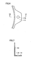
Fig. 6 is a plan view of a positioning hole formed in a flange portion of the fastening ring in the first embodiment. -
Fig. 7 is a sectional view taken along a line VII-VII and seen in the direction of arrows inFig. 6 . -
Fig. 8 is a sectional view showing a method for manufacturing a stator in a second embodiment. -
Fig. 9 is a plan view of a positioning hole formed in a flange portion of a fastening ring in a second embodiment. -
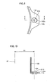
Fig. 10 is a sectional view taken along a line X-X and seen in the direction of arrows inFig. 9 . -
Fig. 11 is a sectional view showing a method for manufacturing a stator in a third embodiment. -
Fig. 12 is a plan view of a positioning hole formed in a flange portion of a fastening ring of the third embodiment. -
Fig. 13 is a sectional view taken along a line XIII-XIII and seen in the direction of arrows inFig. 12 . -
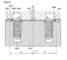
Fig. 14 is a sectional view showing a method for manufacturing a stator in a fourth embodiment. -
Fig. 15 is a plan view showing a positioning hole formed in a flange portion of a fastening ring in the fourth embodiment. -
Fig. 16 is a sectional view taken along a line XVI-XVI and seen in the direction of arrows inFig. 12 . - A stator in embodiments based on the present invention will be described hereinafter with reference to the drawings. When any reference to a number, an amount and the like is made in embodiments described below, the scope of the present invention is not necessarily limited to that number, amount and the like unless otherwise specified. In addition, in the description below, the same or corresponding parts have the same reference numbers allotted, and description thereof may not be repeated.
- Referring to
Figs. 1 and2 , astator 1 has anannular stator core 501 having a stator winding.Stator core 501 is resin-sealed and the resin-sealedstator core 501 is accommodated in a case which is referred to as a cooling jacket. The cooling jacket is configured of afastening ring 100 located outsidestator core 501, aninner ring 200 located outsidestator core 501, and coil end covers 300, 400 located on coil ends at the either end ofstator core 501. - As shown in
Fig. 2 ,stator core 501 has the outer circumferential surface onto whichfastening ring 100 is fixed.Fastening ring 100 has three points on the circumference of the ring at intervals of 120 degrees, each provided with aflange portion 110 extending outwardly in the radial direction. Eachflange portion 110 is provided with a fixinghole 110h. - Fixing
hole 110h provided inflange portion 110 is provided at an accurate position relative to a central position A1 ofstator core 501 serving as a rotational axis of a rotating electric machine. A method for manufacturing a stator including the step of openingfixing hole 110h will be described below. It is noted that sectional views shown in the followingFigs. 3 to 5 correspond to sections taken along a line IV-IV and seen in the direction of arrows inFig. 2 . - As shown in
Fig. 3 ,stator core 501 is positioned and fixed on a centeringjig 700 such that central position A1 ofstator core 501 agrees with the rotational axis of a rotating electric machine. Centeringjig 700 is provided with an annularconcave region 701 for receiving a lower end ofstator core 501 and includes an innerdiameter retaining member 702 pressing onstator core 501 outwardly in the radial direction from the inner circumferential surface side ofstator core 501.Stator core 501 pressed on outwardly by innerdiameter retaining member 702 completes positioning ofstator core 501. - Meanwhile, as shown in
Fig. 4 ,fastening ring 100 is heated by aheater 600 and keeps its inner diameter in an enlarged state. Insidefastening ring 100 with the enlarged inner diameter,stator core 501 is accommodated. Subsequently,fastening ring 100 is cooled, causingfastening ring 100 to have a contracted diameter. As a result,fastening ring 100 is fixed onto the outer circumferential surface ofstator core 501. - Next, referring to
Fig. 5 , withstator core 501 fixed by centeringjig 700, fixinghole 110h is formed by drilling with a drill DI inflange portion 110 provided onfastening ring 100 forstator core 501, using central position A1 as a reference for positioning. As shown inFigs. 6 and 7 , fixinghole 110h is opened to be located at a distance R1 relative to central position A1. In a plan view, the fixinghole 110h is opened at a predetermined central angle interval (for example, intervals of 120°) relative to central position A1. - In this way, the stator and the method for manufacturing the stator in the first embodiment includes the steps of positioning and fixing
stator core 501 on centeringjig 700 such that central position A1 ofstator core 501 agrees with the rotational axis of a rotating electric machine and forming fixinghole 110h inflange portion 110 provided onfastening ring 100 forstator core 501, using central position A1 as a reference for positioning, withstator core 501 fixed by centeringjig 700. 34 Employment of these steps allows fixinghole 110h to be formed at an accurate position relative to central position A1 without being affected by occurrence of deviation caused by heating andcooling fastening ring 100. Consequently, it is now possible to form a clearance of as-designed value between the stator and a rotor for an air gap, and therefore, an enhanced performance of a rotating electric machine can be achieved. In addition, center misalignment between the stator and the rotor is suppressed, and noise reduction of the rotating electric machine can also be achieved. - Referring to
Figs. 8 to 10 , a description will be given below of the stator and the method for manufacturing the same in the present embodiment. The stator in the present embodiment is characterized by having a hole which serves as a fixinghole 110h provided inflange portion 110 provided onfastening ring 100 and which is formed by fixation of ahollow rivet 810 to apilot hole 110m prepared inflange portion 110. The step of forming fixinghole 110h will be described below. It is noted that steps until fixingfastening ring 100 to astator core 501 are same as those in the first embodiment described above. - As shown in
Fig. 8 , on centeringjig 700 and exterior tofastening ring 100, apositioning pin 800 is provided in advance at an accurate position relative to central position A1.Hollow rivet 810 is mounted onpositioning pin 800. Withhollow rivet 810 mounted onpositioning pin 800,fastening ring 100 is fixed ontostator core 501. Sinceflange portion 110 offastening ring 100 is in advance provided withpilot hole 110m,positioning pin 800 andhollow rivet 810 do not interfere withflange portion 110. - Subsequently, as shown in
Figs. 9 and 10 ,hollow rivet 810 protruding on a surface offlange portion 110 is subjected to an outwardly folding process (swaging), and fixation ofhollow rivet 810 toflange portion 110 is thereby completed.Positioning pin 800 is provided at distance R1 relative to central position A1 . Accordingly, fixinghole 110h is opened to be located at distance R1 relative to central portion A1. In a plan view, fixinghole 110h is opened at a predetermined central angle interval (for example, intervals of 120°) relative to central position A1. - In this way, the stator and the method for manufacturing the same in the present embodiment also provide the same function and effects as those in the first embodiment above.
- Referring to
Figs. 11 to 13 , a description will be given below of the stator and the method for manufacturing the same in the present embodiment. The stator in the present embodiment is characterized by having a hole which serves as a fixinghole 110h provided inflange portion 110 provided onfastening ring 100 and which is formed by performing press punching onflange portion 110. The step of forming fixinghole 110h will be described below. It is noted that steps until fixingfastening ring 100 to astator core 501 are same as those in the first embodiment described above. - As shown in
Fig. 8 , in centeringjig 700 and exterior tofastening ring 100, aclearance hole 703 is provided in advance at an accurate position relative to central position A1. Withflange portion 110 placed on centeringjig 700,flange portion 110 is punched through by a punch P1. This results in formation of a punchingburr portion 110p in an approximately cylindrical shape as well as formation of fixinghole 110h defined by punchingburr portion 110p, as shown inFigs. 12 and 13 . -
Clearance hole 703 and punch PI are provided to be located at distance R11 relative to central position A1. Accordingly, fixinghole 110h is opened to be located at distance R1 relative to central portion A1. In a plan view, fixinghole 110h is opened at a predetermined central angle interval (for example, intervals of 120°) relative to central position A1. - In this way, the stator and the method for manufacturing the same in the present embodiment also provide the same function and effects as those in the first embodiment described above.
- In the methods for manufacturing a stator in the above-described first to third embodiments, the step of fixing
fastening ring 100 onto stator core is finished before formation of fixinghole 110h, which allows fixinghole 110h to be formed at an accurate position relative to central position A1 without being affected by occurrence of deviation caused by heating and cooling offastening ring 100. - After formation of fixing
hole 110h, however, it is necessary to perform the step of resin-molding the stator core. At this time, in injecting a mold resin,fastening ring 100 is heated and cooled again, and consequently, a positional deviation of fixinghole 110h may occur. In such a case, a hole formed by performing resin-molding onpilot hole 110m may be used as fixinghole 110h, as shown below. - As shown in
Fig. 14 , in the step of positioning and fixingstator core 501 on a jig,stator core 501 having the outer circumferential surface to whichfastening ring 100 is fastened is placed within cavities 1000C, 2000C formed by alower mold 1000 and anupper mold 2000 for resin-molding. -
Lower mold 1000 andupper mold 2000 have portions circumferentially outward tofastening ring 100 which are provided with a resin introducingconcave portion 1000h and ahole forming pin 2000p, respectively. Resin introducingconcave portion 1000h is located belowpilot hole 110m provided inflange portion 110, and hole formingpin 2000p is provided to pass throughpilot hole 110m and abut on the base of resin introducingconcave portion 1000h. Further, hole formingpin 2000p is provided at an accurate position relative to central portion A1. - In the above-described configuration, introduction of a resin through a
resin introducing conduit 2100 intocavities hole forming pin 2000p. As a result,pilot hole 110m provided inflange portion 110 is covered with aresin 110r, while fixinghole 110h is formed in a region wherehole forming pin 2000p is located, as shown inFigs. 15 and 16 . - Hole forming
pin 2000p is provided to be located at distance R1 relative to central position A1. Accordingly, fixinghole 110h is opened to be located at distance R1 relative to central portion A1. In a plan view, fixinghole 110h is opened at a predetermined central angle interval (for example, intervals of 120°) relative to central position A1. - As such, according to the stator and the method for manufacturing the same in the present embodiment, since fixing
hole 110h is concurrently formed with the step of resin-molding the stator core, fixinghole 110h can be formed at an accurate position relative to central position A1, without being affected by occurrence of deviation caused by heating and cooling offastening ring 100 and by occurrence of deviation caused by heating and cooling in resin-molding. As a result, it is now possible to form a clearance of as-designed value between the stator and a rotor for an air gap, and therefore, an enhanced performance of a rotating electric machine can be achieved. In addition, center misalignment between the stator and the rotor is suppressed, and noise reduction of the rotating electric machine can be achieved. - While the embodiments of the present invention have been described as above, it should be understood that the embodiments disclosed herein are illustrative and non-restrictive in every respect. The scope of the present invention is defined by the terms of the claims, and is intended to include any modifications within the scope and meaning equivalent to the terms of the claims.
- 1 stator; 100 fastening ring; 110 flange portion; 110h fixing hole; 110m pilot hole; 110p punching burr portion; 110r resin; 200 inner ring; 300, 400 coil end cover; 501 stator core; 600 heater; 700 centering jig; 701 concave region; 702 inner diameter retaining member; 703 clearance hole; 800 positioning pin; 810 hollow rivet; 1000C, 2000C cavity; 1000h resin introducing concave portion, 2000p hole forming pin; 2100 resin introducing conduit; A1 central position; D1 drill; P1 punch
Claims (12)
- A method for manufacturing a stator having an annular form and for use in a rotating electric machine, comprising the steps of:positioning and fixing a stator core (501) on a jig (700, 1000, 2000) such that a central position (A1) of said stator core (501) agrees with a rotational axis of a rotating electric machine; andforming a fixing hole (110h) in a flange portion (110) provided on a fastening ring (100) for said stator core (501), using said central position (A1) as a reference for positioning, with said stator core (501) fixed by said jig (700, 1000, 2000).
- The method for manufacturing a stator according to claim 1, wherein
said step of positioning and fixing said stator core (501) on a jig includes the steps of:positioning and fixing said stator core (501) on a centering jig (700) such that said central position (A1) of said stator core (501) agrees with a rotational axis of a rotating electric machine; andfixing said fastening ring (100) onto an outer circumferential surface of said stator core (501), with said stator core (501) fixed by said centering jig (700). - The method for manufacturing a stator according to claim 2, wherein said step of forming said fixing hole (110h) in said flange portion (110) includes the step of performing drilling on said flange portion (110) with a drill, using said center position (A1) as a reference for positioning.
- The method for manufacturing a stator according to claim 2, wherein said step of forming said fixing hole (110h) in said flange portion (110) includes the step of fixing a hollow rivet (810) to a pilot hole (110m) provided in said flange portion (110), using said center position (A1) as a reference for positioning.
- The method for manufacturing a stator according to claim 2, wherein
said step of forming said fixing hole (110h) in said flange portion (110) includes the step of performing punching on said flange portion (110) by press punching, using said center position (A1) as a reference for positioning. - The method for manufacturing a stator according to claim 1, wherein
said step of positioning and fixing said stator core (501) on a jig includes the step of fixing said stator core (501) having an outer circumferential surface fastened by said fastening ring (100), within a mold (1000, 2000) for resin-molding. - The method for manufacturing a stator according to claim 6, wherein
in said step of forming said fixing hole (110h) in said flange portion (110), the step of performing resin-molding said fixing hole (110h) on a pilot hole (110m) provided in said flange portion (110) is performed in and simultaneously with the step of performing resin-molding on said stator core (501) fixed within said mold (1000, 2000). - A stator having an annular form and for use in a rotating electric machine, comprising:a stator core (501); anda fastening ring (100) fixed onto an outer circumferential surface of said stator core (501),said fastening ring being provided with a flange portion (110) having a fixing hole (110h) formed relative to a central position (A1) of said stator core (501) serving as a rotational axis of a rotating electric machine.
- The stator according to claim 8, wherein
said fixing hole (110h) is a hole formed by performing drilling on said flange portion (110). - The stator according to claim 8, wherein
said fixing hole (110h) is a hole formed by fixation of a hollow rivet (810) to a pilot hole (110m) provided in said flange portion (110). - The stator according to claim 8, wherein
said fixing hole (110h) is a hole formed by performing press punching on said flange portion (110). - The stator according to claim 8, wherein
said fixing hole (110h) is a hole formed by performing resin-molding on a pilot hole (110m) provided in said flange portion (110).
Applications Claiming Priority (1)
| Application Number | Priority Date | Filing Date | Title |
|---|---|---|---|
| PCT/JP2009/057564 WO2010119519A1 (en) | 2009-04-15 | 2009-04-15 | Stator and method of producing the same |
Publications (2)
| Publication Number | Publication Date |
|---|---|
| EP2421128A1 true EP2421128A1 (en) | 2012-02-22 |
| EP2421128A4 EP2421128A4 (en) | 2016-12-21 |
Family
ID=42982203
Family Applications (1)
| Application Number | Title | Priority Date | Filing Date |
|---|---|---|---|
| EP09843300.6A Withdrawn EP2421128A4 (en) | 2009-04-15 | 2009-04-15 | STATOR AND PRODUCTION METHOD THEREFOR |
Country Status (5)
| Country | Link |
|---|---|
| US (1) | US8973251B2 (en) |
| EP (1) | EP2421128A4 (en) |
| JP (1) | JP5278541B2 (en) |
| CN (1) | CN102396136B (en) |
| WO (1) | WO2010119519A1 (en) |
Cited By (1)
| Publication number | Priority date | Publication date | Assignee | Title |
|---|---|---|---|---|
| DE102014007568A1 (en) * | 2014-05-22 | 2015-11-26 | Daimler Ag | Mounting arrangement of a stator of an electrical machine to a component, in particular for a motor vehicle |
Families Citing this family (9)
| Publication number | Priority date | Publication date | Assignee | Title |
|---|---|---|---|---|
| WO2011101960A1 (en) | 2010-02-17 | 2011-08-25 | トヨタ自動車株式会社 | Rotating electric machine |
| CN102211284B (en) * | 2011-05-13 | 2012-10-31 | 东方电气(乐山)新能源设备有限公司 | Fixture for turning stator core of wind-driven generator |
| JP5790149B2 (en) * | 2011-05-23 | 2015-10-07 | アイシン精機株式会社 | Rotating electrical machine stator and stator retaining ring |
| JP6096894B2 (en) * | 2013-05-31 | 2017-03-15 | 株式会社Top | Rotating machine |
| DE102015217936A1 (en) * | 2015-09-18 | 2017-03-23 | Continental Automotive Gmbh | Method and one-piece tool assembly for manufacturing a stator for an electric machine |
| DE102015217922A1 (en) * | 2015-09-18 | 2017-03-23 | Continental Automotive Gmbh | Method and two-part tool assembly for manufacturing a stator for an electric machine |
| JP6305471B2 (en) * | 2016-07-25 | 2018-04-04 | 本田技研工業株式会社 | Stator manufacturing method and apparatus |
| US10404111B2 (en) | 2017-12-04 | 2019-09-03 | American Axle & Manufacturing, Inc. | Motor and stator crush resistance device |
| US12341402B2 (en) * | 2022-01-20 | 2025-06-24 | Schaeffler Technologies AG & Co. KG | Emotor rotor centering and shipping aid with annular disk and bolt holes |
Family Cites Families (24)
| Publication number | Priority date | Publication date | Assignee | Title |
|---|---|---|---|---|
| US3184173A (en) * | 1962-01-17 | 1965-05-18 | Gen Motors Corp | Stator winding equipment |
| US3490143A (en) * | 1964-06-26 | 1970-01-20 | Bobbie B Hull | Method of manufacturing a core for an electrical inductive device |
| US3787000A (en) * | 1971-05-19 | 1974-01-22 | Ro Band Corp | Wave form coil winding machine |
| JPS58111356A (en) | 1981-12-24 | 1983-07-02 | Nippon Denso Co Ltd | Regulator for voltage |
| IT1208363B (en) * | 1987-04-01 | 1989-06-12 | Aspera Srl | PROCEDURE AND DEVICE FOR THE ASSEMBLY OF SMALL ELECTRIC ROTARY MACHINES AND GROUPS THAT INCLUDE THEM IN PARTICULAR MOTOR-COMPRESSOR GROUPS FOR REFRIGERANT FLUIDS AND MACHINES AND GROUPS ASSEMBLED WITH THE PROCEDURE |
| JP2616219B2 (en) | 1990-11-08 | 1997-06-04 | 三菱電機株式会社 | Electric motor |
| US5584119A (en) * | 1994-11-07 | 1996-12-17 | General Electric Company | Apparatus for setting skew angle |
| US5806169A (en) * | 1995-04-03 | 1998-09-15 | Trago; Bradley A. | Method of fabricating an injected molded motor assembly |
| JPH09261907A (en) | 1996-03-26 | 1997-10-03 | Sankyo Seiki Mfg Co Ltd | Motor |
| US5767596A (en) * | 1996-10-03 | 1998-06-16 | General Electric Company | Dynamoelectric machine and processes for making the same |
| JP2000270510A (en) | 1999-03-15 | 2000-09-29 | Nippon Densan Corp | Motor |
| JP2002315276A (en) | 2001-04-16 | 2002-10-25 | Honda Motor Co Ltd | Method of manufacturing rotor for rotating electric machine |
| FR2841402B1 (en) * | 2002-06-25 | 2004-09-24 | Valeo Equip Electr Moteur | DEVICE FOR GRIPPING AND TRANSFERRING A CROWN OF ELECTRICAL CONDUCTORS, INTENDED FOR REALIZING A WINDING, AND SYSTEM FOR PERFORMING A WINDING USING SUCH A DEVICE |
| US7415758B2 (en) * | 2003-09-10 | 2008-08-26 | Minebea Co., Ltd. | Device to press the shaft of a rotor into a stator housing |
| JP2006174637A (en) | 2004-12-17 | 2006-06-29 | Nissan Motor Co Ltd | Method for manufacturing stator of rotating electric machine |
| JP2006254562A (en) | 2005-03-09 | 2006-09-21 | Nissan Motor Co Ltd | Rotating electric machine |
| JP4816879B2 (en) * | 2005-06-30 | 2011-11-16 | 株式会社富士通ゼネラル | Axial air gap type electric motor |
| JP2008193806A (en) * | 2007-02-05 | 2008-08-21 | Aisin Seiki Co Ltd | motor |
| JP2008220157A (en) | 2007-02-07 | 2008-09-18 | Toyota Motor Corp | Motor and motor manufacturing method |
| JP4682999B2 (en) | 2007-03-16 | 2011-05-11 | トヨタ自動車株式会社 | Stator molding method, stator molding apparatus, and stator structure |
| JP4914288B2 (en) * | 2007-05-02 | 2012-04-11 | 住友電気工業株式会社 | Bus bar unit |
| JP2009077603A (en) | 2007-09-25 | 2009-04-09 | Hitachi Appliances Inc | Electric motor |
| US7886426B2 (en) * | 2008-07-22 | 2011-02-15 | Honda Motor Co., Ltd. | Stator manufacturing apparatus |
| CN101764470B (en) * | 2008-12-24 | 2013-03-13 | 鸿富锦精密工业(深圳)有限公司 | Motor stator combining device and method thereof |
-
2009
- 2009-04-15 US US13/201,174 patent/US8973251B2/en not_active Expired - Fee Related
- 2009-04-15 EP EP09843300.6A patent/EP2421128A4/en not_active Withdrawn
- 2009-04-15 CN CN200980158772.5A patent/CN102396136B/en not_active Expired - Fee Related
- 2009-04-15 JP JP2011509119A patent/JP5278541B2/en not_active Expired - Fee Related
- 2009-04-15 WO PCT/JP2009/057564 patent/WO2010119519A1/en not_active Ceased
Non-Patent Citations (1)
| Title |
|---|
| See references of WO2010119519A1 * |
Cited By (1)
| Publication number | Priority date | Publication date | Assignee | Title |
|---|---|---|---|---|
| DE102014007568A1 (en) * | 2014-05-22 | 2015-11-26 | Daimler Ag | Mounting arrangement of a stator of an electrical machine to a component, in particular for a motor vehicle |
Also Published As
| Publication number | Publication date |
|---|---|
| JPWO2010119519A1 (en) | 2012-10-22 |
| US8973251B2 (en) | 2015-03-10 |
| US20120017425A1 (en) | 2012-01-26 |
| CN102396136B (en) | 2014-06-18 |
| CN102396136A (en) | 2012-03-28 |
| EP2421128A4 (en) | 2016-12-21 |
| WO2010119519A1 (en) | 2010-10-21 |
| JP5278541B2 (en) | 2013-09-04 |
Similar Documents
| Publication | Publication Date | Title |
|---|---|---|
| EP2421128A1 (en) | Stator and method of producing the same | |
| US9160217B2 (en) | Busbar unit and motor | |
| CN112449738B (en) | Wire guide for the rotor of a wound-rotor synchronous motor | |
| EP2410635B1 (en) | Frameless electric motor assembly | |
| US4684179A (en) | Slip ring assembly for method of making same | |
| US8339011B2 (en) | Rotor assembly wire support | |
| WO2008047942A1 (en) | Stator core and rotating electrical machine | |
| EP2816711B1 (en) | Slip ring device for dynamo-electric machine | |
| WO2010116486A1 (en) | Stator and manufacturing method thereof | |
| CN111384800B (en) | Rotor and motor | |
| JP2014161200A (en) | Brushless motor, and method for manufacturing brushless motor | |
| CN112042078B (en) | Wound rotors for synchronous motors | |
| JP2007181377A (en) | Motor manufacturing method and motor | |
| JP2008236934A (en) | Rotor for rotating electrical machine and method for manufacturing the same | |
| JP5114965B2 (en) | Stator core and rotating electric machine | |
| US8375562B2 (en) | Manufacturing method of rotating electric machine and rotating electric machine | |
| KR102020074B1 (en) | Resin molded stator and method of manufacturing the same | |
| JP5150841B2 (en) | Fixing structure between resolver and cylindrical case | |
| US20240364173A1 (en) | Coil assembly | |
| WO2007123171A1 (en) | Rotor for magnet-type generator, magnet-type generator, method of producing rotor for magnet-type generator, and device for producing rotor for magnet-type generator | |
| US20250047181A1 (en) | Stator manufacturing device | |
| JP2021065023A (en) | Manufacturing method of rotary electric machine and manufacturing apparatus of the rotary electric machine | |
| CN103715791A (en) | Motor rotor and manufacturing method thereof | |
| JP7099264B2 (en) | A yoke assembly, a torque detector, and a method for manufacturing the yoke assembly. | |
| JP2008199785A (en) | Stator core and rotating electric machine |
Legal Events
| Date | Code | Title | Description |
|---|---|---|---|
| PUAI | Public reference made under article 153(3) epc to a published international application that has entered the european phase |
Free format text: ORIGINAL CODE: 0009012 |
|
| 17P | Request for examination filed |
Effective date: 20110824 |
|
| AK | Designated contracting states |
Kind code of ref document: A1 Designated state(s): AT BE BG CH CY CZ DE DK EE ES FI FR GB GR HR HU IE IS IT LI LT LU LV MC MK MT NL NO PL PT RO SE SI SK TR |
|
| DAX | Request for extension of the european patent (deleted) | ||
| RAP1 | Party data changed (applicant data changed or rights of an application transferred) |
Owner name: TOYOTA JIDOSHA KABUSHIKI KAISHA |
|
| RA4 | Supplementary search report drawn up and despatched (corrected) |
Effective date: 20161122 |
|
| RIC1 | Information provided on ipc code assigned before grant |
Ipc: H02K 15/14 20060101AFI20161116BHEP Ipc: H02K 5/26 20060101ALN20161116BHEP |
|
| STAA | Information on the status of an ep patent application or granted ep patent |
Free format text: STATUS: REQUEST FOR EXAMINATION WAS MADE |
|
| STAA | Information on the status of an ep patent application or granted ep patent |
Free format text: STATUS: THE APPLICATION IS DEEMED TO BE WITHDRAWN |
|
| 18D | Application deemed to be withdrawn |
Effective date: 20170620 |