EP2421067A1 - Battery pack having waterproof structure - Google Patents
Battery pack having waterproof structure Download PDFInfo
- Publication number
- EP2421067A1 EP2421067A1 EP11006770A EP11006770A EP2421067A1 EP 2421067 A1 EP2421067 A1 EP 2421067A1 EP 11006770 A EP11006770 A EP 11006770A EP 11006770 A EP11006770 A EP 11006770A EP 2421067 A1 EP2421067 A1 EP 2421067A1
- Authority
- EP
- European Patent Office
- Prior art keywords
- battery pack
- casing
- battery
- external connection
- pack
- Prior art date
- Legal status (The legal status is an assumption and is not a legal conclusion. Google has not performed a legal analysis and makes no representation as to the accuracy of the status listed.)
- Granted
Links
- 238000005192 partition Methods 0.000 claims abstract description 32
- 238000004891 communication Methods 0.000 claims description 25
- 238000005476 soldering Methods 0.000 claims description 15
- XLYOFNOQVPJJNP-UHFFFAOYSA-N water Substances O XLYOFNOQVPJJNP-UHFFFAOYSA-N 0.000 description 61
- 238000007599 discharging Methods 0.000 description 25
- 230000004308 accommodation Effects 0.000 description 21
- 230000002093 peripheral effect Effects 0.000 description 15
- 229910000679 solder Inorganic materials 0.000 description 15
- 125000006850 spacer group Chemical group 0.000 description 14
- 230000002159 abnormal effect Effects 0.000 description 13
- 238000001514 detection method Methods 0.000 description 12
- 238000010276 construction Methods 0.000 description 11
- 229910052751 metal Inorganic materials 0.000 description 11
- 239000002184 metal Substances 0.000 description 11
- 238000003780 insertion Methods 0.000 description 9
- 230000037431 insertion Effects 0.000 description 9
- WABPQHHGFIMREM-UHFFFAOYSA-N lead(0) Chemical compound [Pb] WABPQHHGFIMREM-UHFFFAOYSA-N 0.000 description 9
- 238000003892 spreading Methods 0.000 description 9
- 238000000638 solvent extraction Methods 0.000 description 6
- 230000000694 effects Effects 0.000 description 4
- 238000010586 diagram Methods 0.000 description 3
- 238000009413 insulation Methods 0.000 description 3
- HBBGRARXTFLTSG-UHFFFAOYSA-N Lithium ion Chemical compound [Li+] HBBGRARXTFLTSG-UHFFFAOYSA-N 0.000 description 2
- 230000005856 abnormality Effects 0.000 description 2
- 239000004020 conductor Substances 0.000 description 2
- 239000000428 dust Substances 0.000 description 2
- 238000010292 electrical insulation Methods 0.000 description 2
- 229910001416 lithium ion Inorganic materials 0.000 description 2
- 239000000463 material Substances 0.000 description 2
- 238000000465 moulding Methods 0.000 description 2
- 238000012856 packing Methods 0.000 description 2
- 239000011347 resin Substances 0.000 description 2
- 229920005989 resin Polymers 0.000 description 2
- 238000000926 separation method Methods 0.000 description 2
- 238000003466 welding Methods 0.000 description 2
- 230000002411 adverse Effects 0.000 description 1
- OJIJEKBXJYRIBZ-UHFFFAOYSA-N cadmium nickel Chemical compound [Ni].[Cd] OJIJEKBXJYRIBZ-UHFFFAOYSA-N 0.000 description 1
- 230000007423 decrease Effects 0.000 description 1
- JEIPFZHSYJVQDO-UHFFFAOYSA-N iron(III) oxide Inorganic materials O=[Fe]O[Fe]=O JEIPFZHSYJVQDO-UHFFFAOYSA-N 0.000 description 1
- 238000004519 manufacturing process Methods 0.000 description 1
- 229910052987 metal hydride Inorganic materials 0.000 description 1
- 238000012986 modification Methods 0.000 description 1
- 230000004048 modification Effects 0.000 description 1
- 229910052759 nickel Inorganic materials 0.000 description 1
- PXHVJJICTQNCMI-UHFFFAOYSA-N nickel Substances [Ni] PXHVJJICTQNCMI-UHFFFAOYSA-N 0.000 description 1
- -1 nickel metal hydride Chemical class 0.000 description 1
- 229920003023 plastic Polymers 0.000 description 1
- 239000004033 plastic Substances 0.000 description 1
- 229920000642 polymer Polymers 0.000 description 1
- 230000002787 reinforcement Effects 0.000 description 1
- 230000035939 shock Effects 0.000 description 1
- 229910052710 silicon Inorganic materials 0.000 description 1
- 239000010703 silicon Substances 0.000 description 1
- 238000004078 waterproofing Methods 0.000 description 1
Images


Classifications
-
- H—ELECTRICITY
- H01—ELECTRIC ELEMENTS
- H01M—PROCESSES OR MEANS, e.g. BATTERIES, FOR THE DIRECT CONVERSION OF CHEMICAL ENERGY INTO ELECTRICAL ENERGY
- H01M10/00—Secondary cells; Manufacture thereof
- H01M10/42—Methods or arrangements for servicing or maintenance of secondary cells or secondary half-cells
-
- H—ELECTRICITY
- H01—ELECTRIC ELEMENTS
- H01M—PROCESSES OR MEANS, e.g. BATTERIES, FOR THE DIRECT CONVERSION OF CHEMICAL ENERGY INTO ELECTRICAL ENERGY
- H01M50/00—Constructional details or processes of manufacture of the non-active parts of electrochemical cells other than fuel cells, e.g. hybrid cells
- H01M50/20—Mountings; Secondary casings or frames; Racks, modules or packs; Suspension devices; Shock absorbers; Transport or carrying devices; Holders
- H01M50/204—Racks, modules or packs for multiple batteries or multiple cells
- H01M50/207—Racks, modules or packs for multiple batteries or multiple cells characterised by their shape
- H01M50/216—Racks, modules or packs for multiple batteries or multiple cells characterised by their shape adapted for button or coin cells
-
- H—ELECTRICITY
- H01—ELECTRIC ELEMENTS
- H01M—PROCESSES OR MEANS, e.g. BATTERIES, FOR THE DIRECT CONVERSION OF CHEMICAL ENERGY INTO ELECTRICAL ENERGY
- H01M50/00—Constructional details or processes of manufacture of the non-active parts of electrochemical cells other than fuel cells, e.g. hybrid cells
- H01M50/20—Mountings; Secondary casings or frames; Racks, modules or packs; Suspension devices; Shock absorbers; Transport or carrying devices; Holders
- H01M50/296—Mountings; Secondary casings or frames; Racks, modules or packs; Suspension devices; Shock absorbers; Transport or carrying devices; Holders characterised by terminals of battery packs
-
- H—ELECTRICITY
- H04—ELECTRIC COMMUNICATION TECHNIQUE
- H04M—TELEPHONIC COMMUNICATION
- H04M1/00—Substation equipment, e.g. for use by subscribers
- H04M1/02—Constructional features of telephone sets
- H04M1/0202—Portable telephone sets, e.g. cordless phones, mobile phones or bar type handsets
- H04M1/0249—Details of the mechanical connection between the housing parts or relating to the method of assembly
- H04M1/0252—Details of the mechanical connection between the housing parts or relating to the method of assembly by means of a snap-on mechanism
-
- H—ELECTRICITY
- H01—ELECTRIC ELEMENTS
- H01M—PROCESSES OR MEANS, e.g. BATTERIES, FOR THE DIRECT CONVERSION OF CHEMICAL ENERGY INTO ELECTRICAL ENERGY
- H01M50/00—Constructional details or processes of manufacture of the non-active parts of electrochemical cells other than fuel cells, e.g. hybrid cells
- H01M50/20—Mountings; Secondary casings or frames; Racks, modules or packs; Suspension devices; Shock absorbers; Transport or carrying devices; Holders
- H01M50/204—Racks, modules or packs for multiple batteries or multiple cells
- H01M50/207—Racks, modules or packs for multiple batteries or multiple cells characterised by their shape
- H01M50/213—Racks, modules or packs for multiple batteries or multiple cells characterised by their shape adapted for cells having curved cross-section, e.g. round or elliptic
-
- H—ELECTRICITY
- H01—ELECTRIC ELEMENTS
- H01M—PROCESSES OR MEANS, e.g. BATTERIES, FOR THE DIRECT CONVERSION OF CHEMICAL ENERGY INTO ELECTRICAL ENERGY
- H01M50/00—Constructional details or processes of manufacture of the non-active parts of electrochemical cells other than fuel cells, e.g. hybrid cells
- H01M50/20—Mountings; Secondary casings or frames; Racks, modules or packs; Suspension devices; Shock absorbers; Transport or carrying devices; Holders
- H01M50/218—Mountings; Secondary casings or frames; Racks, modules or packs; Suspension devices; Shock absorbers; Transport or carrying devices; Holders characterised by the material
- H01M50/22—Mountings; Secondary casings or frames; Racks, modules or packs; Suspension devices; Shock absorbers; Transport or carrying devices; Holders characterised by the material of the casings or racks
- H01M50/227—Organic material
-
- H—ELECTRICITY
- H01—ELECTRIC ELEMENTS
- H01M—PROCESSES OR MEANS, e.g. BATTERIES, FOR THE DIRECT CONVERSION OF CHEMICAL ENERGY INTO ELECTRICAL ENERGY
- H01M50/00—Constructional details or processes of manufacture of the non-active parts of electrochemical cells other than fuel cells, e.g. hybrid cells
- H01M50/50—Current conducting connections for cells or batteries
- H01M50/543—Terminals
- H01M50/547—Terminals characterised by the disposition of the terminals on the cells
- H01M50/548—Terminals characterised by the disposition of the terminals on the cells on opposite sides of the cell
-
- H—ELECTRICITY
- H01—ELECTRIC ELEMENTS
- H01M—PROCESSES OR MEANS, e.g. BATTERIES, FOR THE DIRECT CONVERSION OF CHEMICAL ENERGY INTO ELECTRICAL ENERGY
- H01M50/00—Constructional details or processes of manufacture of the non-active parts of electrochemical cells other than fuel cells, e.g. hybrid cells
- H01M50/50—Current conducting connections for cells or batteries
- H01M50/543—Terminals
- H01M50/552—Terminals characterised by their shape
- H01M50/559—Terminals adapted for cells having curved cross-section, e.g. round, elliptic or button cells
-
- Y—GENERAL TAGGING OF NEW TECHNOLOGICAL DEVELOPMENTS; GENERAL TAGGING OF CROSS-SECTIONAL TECHNOLOGIES SPANNING OVER SEVERAL SECTIONS OF THE IPC; TECHNICAL SUBJECTS COVERED BY FORMER USPC CROSS-REFERENCE ART COLLECTIONS [XRACs] AND DIGESTS
- Y02—TECHNOLOGIES OR APPLICATIONS FOR MITIGATION OR ADAPTATION AGAINST CLIMATE CHANGE
- Y02E—REDUCTION OF GREENHOUSE GAS [GHG] EMISSIONS, RELATED TO ENERGY GENERATION, TRANSMISSION OR DISTRIBUTION
- Y02E60/00—Enabling technologies; Technologies with a potential or indirect contribution to GHG emissions mitigation
- Y02E60/10—Energy storage using batteries
Definitions
- the present invention relates to a battery pack which is detachably attached to electric equipment such as electric tool and supplies electric power to the electric equipment.
- Electric equipment such as electric tool includes a battery pack which includes a rechargeable battery and is detachably attached to the main unit of the electric equipment. Such electric equipment is useful as a cordless-type tool in construction sites and the like. Since the battery pack can be detached from the main unit of the electric equipment, the detached battery pack can be attached to a charger so that the battery pack is charged. Thus, the battery pack can be repeatedly used.
- a charger for charging this type of battery pack has been in practical use which includes an attachment portion that is arranged on the upper surface of the charger case and detachably holds the battery pack. Charging terminals are exposed from this attachment portion.
- the battery pack has a lock structure that holds the battery pack on the attachment portion of the charger for preventing the battery pack from being detached from the attachment portion.
- the lock structure can include a hook-shaped lock hook 97 that protrudes from the battery pack 90 and can engage with a lock opening 93 arranged in the attachment portion 92 whereby preventing detachment of the battery pack 90.
- the battery pack 90 includes a spring that biases the lock hook 97 in the protruding direction. When users press this lock hook 97 with their finger, the lock hook 97 can be disengaged from the lock opening.
- the battery pack 90 has a structure that allows the lock hook 97 to protrude/retract from/into the battery pack.
- the battery pack preferably has a waterproof structure.
- the battery pack since the battery pack has the movable part in the lock structure, it is not easy to provide a completely waterproof structure in the battery pack.
- the lock hook since the lock hook is required to move, the opening is necessarily formed to allow the lock hook to protrude. For this reason, there is a problem that water may come into the casing of the battery pack through this opening.
- water if water comes into the battery pack, it is not easy to drain the water from the battery pack. The water may move to the rechargeable battery or the electronic circuit board, and may cause unintended electric conduction.
- the battery pack has an opening that is arranged in a part where the output terminals are arranged for connection to the electric equipment or the like.
- the output terminals are exposed through the opening externally of the battery pack.
- water may come into the case through this opening.
- the present invention is devised to solve the above problems. It is a main object to provide a reliable battery pack having an improved waterproof structure.
- a battery pack according to a first aspect of the present invention can be attached to electric equipment and a charger 100, and includes a plurality of rechargeable batteries 39, a battery holder 70, a pack circuit board 74, a casing 31, external connection terminals 33 and a lock hook 37b.
- the electric equipment can be supplied with electric power from the rechargeable batteries.
- the charger 100 can charge the rechargeable batteries of the battery pack.
- the plurality of rechargeable batteries can supply electric power to the electric equipment.
- the battery holder 70 holds the rechargeable batteries 39.
- the pack circuit board 74 includes an electronic circuit connected to the rechargeable batteries 39.
- the casing 31 accommodates the battery holder 70 and the pack circuit board 74.
- the external connection terminals 33 are fastened onto the pack circuit board 74, and are connected to the rechargeable batteries 39.
- the external connection terminals are exposed externally of the casing 31.
- the lock hook 37b protrudes from a surface of the casing 31, and holds the battery pack with the battery pack being attached to the charger 100 and/or the electric equipment.
- a hook opening window 24 is opened in one of the surfaces of the casing so that the lock hook 37b can protrude from the surface of the casing 31.
- a partition rib 25 extends inside the casing 31 along the hook opening window 24 for the lock hook 37b. The edge of the partition rib 25 contacts the pack circuit board 74. According to this construction, since the partition rib contacts only a part of pack circuit board, it is possible to the possibility that water comes into a part inside the pack circuit board.
- a battery pack according to a second aspect of the present invention can further include terminal ribs 26 that extend inside the casing 31 to enclose the external connection terminals 33. The edges of the external connection terminals 33 contact the pack circuit board 74.
- a battery pack according to a third aspect of the present invention can be attached to a charger 100, and includes a plurality of rechargeable batteries 39, a battery holder 70, a pack circuit board 74, a casing 31, external connection terminals 33 and a lock hook 37b.
- the charger 100 can charge the rechargeable batteries of the battery pack.
- the battery holder 70 holds the rechargeable batteries 39.
- the pack circuit board 74 includes an electronic circuit connected to the rechargeable batteries 39.
- the casing 31 accommodates the battery holder 70 and the pack circuit board 74.
- the external connection terminals 33 are fastened onto the pack circuit board 74 and are connected to the rechargeable batteries 39.
- the external connection terminals are exposed externally of the casing 31.
- the lock hook 37b protrudes from a surface of the casing 31, and holds the battery pack with the battery pack being attached to the charger 100.
- a hook opening window 24 is opened in one of the surfaces of the casing so that the lock hook 37b can protrude from the surface of the casing 31.
- a drain hole 28 is opened in another surface of the casing other than the one of the surfaces on which the hook opening window 24 is opened.
- a partition rib 25 is arranged between a path and the electronic circuit so that the path is separated from the electronic circuit. The path extends inside the casing 31 from the hook opening window 24 and communicates with the hook opening window 24.
- the electronic circuit is mounted in the pack circuit board 74.
- the hook opening window 24 communicates with the drain hole 28 through the communication path, which is formed by the partition rib 25.
- the partition rib can prevent that the water flows toward the electronic circuit, which is mounted on the pack circuit board.
- the water is guided to the drain hole after coming into the battery pack. Therefore, it is possible to effectively prevent unintended electric conduction.
- the communication path can be formed at least partially on the upper surface of the battery holder 70. According to this construction, since the communication path can be formed on the back surface of the battery holder, which accommodates the rechargeable batteries, it is possible to effectively prevent that water comes onto the rechargeable batteries.
- the upper surface of the battery holder 70 is inclined at a downward angle toward the drain hole 28. According to this construction, since, even if water comes into the battery pack through the hook opening window, the water can be guided to the drain hole by the inclined upper surface along the communication path, the water can be easily drained out of the battery pack.
- the edges of the partition rib 25 can partially contact the surface of the external connection terminal 33.
- the external connection terminal 33 can have a soldering part that is arranged for wiring in proximity to the contact part of the external connection terminal with the partition rib 25.
- a protruding stopper portion 88 can be formed in this soldering part.
- the protruding stopper portion can limit spreading of solder in soldering. As a result, it is possible to avoid that the solder spreads to the contact part. For this reason, it is possible to avoid that the bulge of spreading solder prevents the contact between the partition rib and the pack circuit board in the contact part.
- the partition rib can surely contact the pack circuit board. Therefore, it is possible to effectively prevent that water comes into the battery pack.
- the protruding stopper portion 88 can be formed on the surface of the external connection terminal 33 by drawing. According to this construction, the protruding stopper portion can be easily formed integrally with the surface of the external connection terminal.
- a holding rib portion 27 can be arranged inside the casing 31.
- the holding rib portion 27 guides the upper end of the external connection terminal 33, and holds the upper end of the external connection terminal 33 from the both sides of the external connection terminal 33. According to this construction, the external connection terminal can be stably held. Therefore, it is possible to improve the reliability of the battery pack.
- the holding rib portion 27 can sandwich the upper part of the external connection terminal 33. According to this construction, the holding rib can securely hold the external connection terminal from the upper surface of the external connection terminal.
- a plurality of structural elements of the present invention may be configured as a single part that serves the purpose of a plurality of elements, on the other hand, a single structural element may be configured as a plurality of parts that serve the purpose of a single element. Also, the description of some of examples or embodiments may be applied to other examples, embodiments or the like.
- Figs. 1 to 23 show a battery pack according to an embodiment of the present invention.
- Fig. 1 is a perspective view showing a battery pack 30.
- Fig. 2 is a perspective view showing the battery pack 30 shown in Fig. 1 as viewed from the rear side.
- Fig. 3 is a plan view of the battery pack 30 shown in Fig. 1 .
- Fig. 4 is a plan view of the battery pack 30 shown in Fig. 1 .
- Fig. 5 is a perspective view showing the battery pack 30 shown in Fig. 1 as viewed from the bottom side.
- Fig. 6 is an exploded perspective view of the battery pack 30 shown in Fig. 5 showing a label attachment area.
- Fig. 7 is an exploded perspective view showing the battery pack 30 shown in Fig. 1 .
- Fig. 8 is an exploded perspective view showing the battery pack 30 shown in Fig. 7 as viewed from the rear side.
- Fig. 9 is a bottom view showing an upper case 31A shown in Fig. 4 from the back side.
- Fig. 10 is a perspective horizontal cross-sectional view showing the battery pack 30 with the upper part of the battery pack 30 being cut away taken along the line X-X in Fig. 3 .
- Fig. 11 is a perspective view showing the battery pack 30 shown in Fig. 3 with the upper case 31A being removed.
- Fig. 12 is a perspective view showing the battery pack 30 shown in Fig. 11 as viewed from the front side.
- Fig. 13 is a plan view of a battery holder 70 shown in Fig. 7 .
- Fig. 14 is a perspective view showing the battery holder 70 shown in Fig. 13 before soldering.
- Fig. 15 is a perspective view showing the battery pack 30 shown in Fig. 14 as viewed from the rear side.
- Fig. 16 is an exploded perspective view of the battery holder 70 shown in Fig. 14 .
- Fig. 17 is a cross-sectional view schematically showing a protruding stopper portion 88 with the protruding stopper portion 88 limiting the spreading of solder 89.
- Fig. 18 is a cross-sectional view schematically showing the spreading of solder 89 in the case where the protruding stopper portion 88 is not formed.
- Fig. 19 is a perspective view showing the upper case 31A shown in Fig. 9 .
- Fig. 19 is a perspective view showing the upper case 31A shown in Fig. 9 .
- Fig. 20 is an enlarged perspective view showing a holding rib portion 27 of the upper case 31A shown in Fig. 19 .
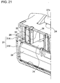
- Fig. 21 is a cross-sectional view showing the battery pack 30 shown in Fig. 4 taken along the line XXI-XXI.
- Fig. 22 is a cross-sectional view showing the battery pack 30 shown in Fig. 3 taken along the line XXII-XXII.
- Fig. 23 is a horizontal sectional view showing the battery pack 30 shown in Fig. 3 taken along the line XXIII-XXIII.
- the battery pack 30 according to this example will be illustratively described to be applied to an electric tool as electric equipment to which the battery pack 30 is mounted.
- the illustrated battery pack 30 includes a plurality of rechargeable batteries 39, the battery holder 70, battery lead plates 80, a pack circuit board 74, a casing 31, external connection terminals 33, and a lock hook 37b.
- the battery holder 70 holds the plurality of rechargeable batteries 39.
- the battery lead plates 80 connect the end surfaces of the rechargeable batteries 39 to each other.
- the pack circuit board 74 includes an electronic circuit connected to the rechargeable batteries 39.
- the casing 31 accommodates the battery holder 70 and the pack circuit board 74.
- the external connection terminals 33 are fastened onto the pack circuit board 74, and are connected to the rechargeable batteries 39.
- the external connection terminals 33 are exposed externally of the casing 31.
- the lock hook 37b protrudes from a surface of the casing 31, and holds the battery pack with the battery pack being attached to a battery pack charger 100.
- the casing 31 has a box-shaped outward appearance as shown in Figs. 1 to 4 .
- the corner parts of the casing 31 are rounded.
- the casing 31 has slots 38 in the surface of the casing 31.
- the external connection terminals 33 are exposed from the slots 38.
- the external connection terminals 33 can be connected to the electric tool as electric equipment, or connection terminals 3 of the battery pack charger 100.
- the casing includes an attachment protruding portion 37 that holds the battery pack 30 with the battery pack 30 being mounted to the electric tool or the battery pack charger 100 after the battery pack 30 is mounted to the electric tool or the battery pack charger 100.
- the casing 31 is formed of resin or the like having excellent insulation and reinforcement.
- the illustrated external connection terminals 33 include charging/discharging terminals 34, and signal terminals 35.
- the charging/discharging terminals 34 are arranged on the both sides.
- the signal terminals 35 are arranged between the charging/discharging terminals 34.
- a label 7 is attached onto the back surface of the casing 31.
- the label 7 shows information including rating of the battery pack, cautions and the like. Accordingly, a label attachment area 8 is formed on the surface of the casing 31. In the case of Fig. 6 , the label attachment area 8 is located on the bottom of a lower case 31 B.
- the casing 31 includes divided portions of the upper and lower cases 31A and 31 B as shown in the exploded perspective views of Figs. 7 and 8 .
- Accommodation space is formed inside the casing 31.
- the casing 31 accommodates the battery holder 70, the pack circuit board 74, and the attachment protruding portion 37 in the accommodation space.
- the hook opening window 24 is opened in the upper case 31A.
- the lock hook 37b is exposed from the hook opening window 24.
- the lock hook 37b composes a lock structure, which holds the battery pack 30 for preventing from detachment of the battery pack 30 after the battery pack 30 is mounted to the battery pack charger 100.
- the lock hook 37b can compose a lock structure, which holds the battery pack 30 for preventing from detachment of the battery pack 30 after the battery pack 30 is mounted to the electric equipment.
- the battery pack according to this embodiment has construction that, even if water comes into the battery pack through the gap GP in the hook opening window 24, the water can be prevented from coming in contact with electronic components and the like, and can be drained out of the battery pack.
- the upper case 31A includes a partition rib 25 that extends inward of the casing from the hook opening window 24.
- the partition rib 25 partitions the interior of the casing so that, if water comes into the battery pack through the hook opening window 24, the water does not come into areas other than the area of the pack circuit board 74 formed by the partition rib 25, in other words, the water does not come into the area where the electronic circuit is mounted on the pack circuit board 74.
- the lock hook 37b has a rectangular U shape as viewed in the plan view.
- the hook opening window 24 is also opened in a rectangular U shape as viewed in the plan view corresponding to the lock hook 37b.
- the partition rib 25 also extends along the edges of this rectangular U shape inside the casing. That is, the partition rib has a shape having one side the both end parts of which protrude toward the pack circuit board 74.
- the pack circuit board 74 is not entirely separated by the partition rib 25, but the bottom edges 25U on the both end parts of the one side of the partition rib 25 contact the surface of the pack circuit board 74 on outer peripheral parts 74SF of the pack circuit board 74 (rectangular shapes as viewed in the plan view).
- Terminal ribs 26 are formed on the inner surface of the upper case 31A, and define the slots 38.
- the terminal rib 26 surrounds corresponding one of the external connection terminals 33, which are exposed from the slots 38. Since the terminal rib 26 surrounds corresponding one of the external connection terminals 33, the external connection terminals 33 can be separated and insulated from each other in the casing 31.
- the terminal ribs 26 are formed integrally with the upper case 31A, as shown in Figs. 9 , 10 , 19 and the like.
- the terminal rib 26 extends defining corresponding one of the vertical slots 38 inside the casing 31.
- the terminal rib 26 is formed in a quadrangle shape (rectangular shape) as viewed in the plan view.
- the terminal rib 26 partitions the interior of the casing 31 so that, if water comes into the battery pack through the slot from which the external connection terminal 33 is exposed, the water does not come into areas other than a block 74ST of the pack circuit board 74 under the terminal rib 26, in other words, the water does not come into the area where the electronic circuit is mounted on the pack circuit board 74.
- the bottom edges 26U of the terminal rib 25 contact the surface of the outer periphery of the block 74ST of the pack circuit board 74 under the terminal rib 26.
- the outer peripheral parts 74SF of the pack circuit board 74 under the partition rib 25 are located on the hook opening window 24 side.
- the blocks 74ST of the pack circuit board 74 under the terminal ribs 26 are located on the vertical slot 38 side. Water may come into the outer peripheral parts 74SF and the blocks 74ST. However, it is possible to reduce that the water comes into areas other than the outer peripheral parts 74SF and the blocks 74ST. As shown in Fig. 10 , the bottom edges 25U of each of the both end parts of the one side of the partition rib 25 contact three of the four sides (i.e., the outer periphery) of each of the outer peripheral parts 74SF of the pack circuit board 74.
- electronic components are not arranged in the outer peripheral parts 74SF and the blocks 74ST.
- at least water-sensitive electronic components are not arranged in the outer peripheral parts 74SF and the blocks 74ST.
- important electronic components can be arranged on the pack circuit board 74 and can be separated from the outer peripheral parts 74SF and the blocks 74ST.
- electronic components may be arranged on the pack circuit board 74 in the outer peripheral parts 74SF and the blocks 74ST.
- the separation does not always refer to complete waterproofing but includes a structure that can substantially prevent water from coming into the separated area.
- the contact does not always refer to completely tight contact but includes contact which can prevent water from coming into the separated area.
- the contact can include contact having such a small clearance. Since such a small clearance is allowed, the tolerance can be low. Packing or the like is not required to provide a complete waterproof structure. The effective waterproof structure can be simply provided at low cost.
- the rear side (the lower side in Fig. 11 ) of the battery holder 70 is arranged in the part of the lower case 31 B under the hook opening window 24.
- the rechargeable batteries 39 are held in the battery holder 70.
- the battery holder 70 prevents that water comes onto the rechargeable battery 39.
- Drain holes 28 are opened in the lower case 31 B. Specifically, the drain holes 28 are opened in the area of the case where communicates with the hook opening window. In other words, the interior of the case has two separated areas. One of the separated areas is a communication area 28R which communicates with the hook opening window. The other of the separated areas is an accommodation area that accommodates the rechargeable batteries and the like. If water comes into the communication area through the hook opening window, the water is prevented from coming into the accommodation area. Thus, the communication area is waterproofed. In addition, the drain holes are opened in the communication area 28R. As a result, the water can be drained out of the communication area through the drain holes. To achieve this, as shown in Figs.
- a partitioning wall 28K is formed on the lower case 31 B. Together with the partition rib 25 of the upper case 31A, the partitioning wall 28K defines the communication area 28R.
- the battery holder 70 is accommodated in the accommodation area defined by the partitioning wall 28K.
- the communication path is formed which extends from the hook opening window 24 to the drain holes 28 as discussed above. Thus, even if water comes into the communication path through the hook opening window 24, the water can be drained through the drain holes 28.
- the inclined surface 78 is formed at a downward angle toward the drain hole 28 side on the rear-side upper surface of the battery holder 70.
- a gateway 79 is formed in the partitioning wall 28K. Accordingly, it is possible to facilitate moving the water along the inclined surface 78.
- the inclined surface 78 is inclined at a downward angle toward the gateway 79 so that the water is gathered into the gateway 79. Thus, the water can be guided to the drain hole 28 side through the gateway 79. As a result, the water can be drained out of the battery pack 30.
- the lower case has a pair of nut holding ribs 28S.
- Each of the nut holding ribs 28S forms a nut opening that holds a nut.
- a screw threadedly engages with the nut so that the lower case 31 B and the upper case 31A are fastened to each other.
- the communication area 28R is located in the area enclosed by the aforementioned partitioning wall 28K and the end surface of the lower case 31 B between the pair of the nut holding ribs 28S.
- the outside diameter of the nut holding ribs 28S corresponds to the width of the communication area 28R.
- a pair of cylindrical ribs 28T are formed in the communication area 28R.
- the cylindrical ribs 28T hold coil springs that elastically bias the attachment protruding portion 37.
- the pair of cylindrical rib 28T have the outer diameter substantially same as the width of the communication area 28R.
- the communication area 28R is further divided into three areas.
- the drain holes 28 are formed opened at three locations on the rear side of the bottom surface of lower case 31 B. Specifically, the center drain hole 28 is arranged between the pair of cylindrical ribs 28T as shown in Fig. 11 . Each of the other drain holes 28 is arranged between the cylindrical rib 28T and the nut holding rib 28S. Since the drain hole is formed in each of the three divided areas of the communication area 28R, water guided to the three divided areas can be drained out of the these divided areas.
- the aforementioned gateway 79 extends to the area where the center drain hole 28 is formed, in other words, between the pair of the cylindrical ribs 28T.
- the water can be drained through the center drain hole out of this area.
- a larger amount of water can be gathered in the area between the pair of cylindrical ribs 28T so that the gathered water can be collectively drained through the center drain hole 28.
- the three divided areas of the communication area 28R communicate with each other in the part higher than the height of the cylindrical rib 28T. Accordingly, if a larger amount of water gathered in the center area, when the water level rises to the height higher than the cylindrical rib 28T, the water starts flowing into the areas on the right and left sides of the cylindrical ribs 28T, in other words, the areas between the cylindrical ribs 28T and the nut holding ribs 28S. As a result, the water can be drained also through the drain holes 28 on the both sides.
- the drain hole is not limited to the communication area 28R but can be opened in the accommodation area.
- second drain holes 29 are opened in the four corner parts of the accommodation area. Accordingly, even if water undesirably comes into the accommodation area of the battery pack 30, the water is drained from the second drain holes 29 formed in the lower surface of the lower case 31 B, as shown in Figs. 5 and 6 and the like.
- the battery holder 70 holds the rechargeable batteries 39, the pack circuit board 74, the battery lead plates 80, and lead wire lines, as shown in Figs. 13, 14 and 15 .
- the battery holder 70 has battery accommodation space on the lower side, and a circuit board holding portion 75 on the upper side as shown in the exploded perspective view of Fig. 16 .
- the battery accommodation space accommodates the rechargeable batteries 39.
- the circuit board holding portion 75 holds the pack circuit board 74.
- the end surfaces of the rechargeable batteries 39 are exposed from exposed portions 71, which are opened in the end surfaces of the battery holder 70.
- the end surfaces of the rechargeable batteries 39 are connected to each other by the battery lead plates 80.
- a battery core portion is composed of the rechargeable batteries 39, which are held by the battery holder 70.
- the outputs of the battery core portion are connected to the pack circuit board 74 through an output lead plate 82 (lower left side in Fig. 15 ) and a connection lead plate 83B, and a second output lead plate 82B and an output lead wire line 83 (upper right side in Fig. 15 ). Also, the output of the battery core portion, signals from the pack circuit board 74, and the like are provided through the external connection terminals 33.
- the battery lead plates 80 are connected to the pack circuit board 74 through a signal lead line 84. Since high voltage is applied to the output lead wire line 83, a thick conductor line available for high current used is used as the output lead wire line 83. On the other hand, since the signal lead line 84 serves as a signal line, even a thin conductor line can be used as the signal lead line 84.
- the pack circuit board 74 includes the charging/discharging terminals 34, and the signal terminals 35 which serve as the external connection terminals 33.
- the output of the battery core portion is connected to the electric tool or the battery pack charger 100 through the charging/discharging terminals 34.
- the output from the battery core portion is connected to the charging/discharging terminals 34 on the pack circuit board 74 through the second output lead plate 82B and the output lead wire line 83, and the output lead plate 82 and the connection lead plate 83B.
- the connection lead plate 83B is formed separately from the output lead plate 82.
- the connection lead plate 83B may be formed integrally with the output lead plate 82.
- the electronic circuit is mounted on the pack circuit board 74, and is connected to the rechargeable batteries 39.
- the electronic circuit is a protection circuit, which protects the rechargeable batteries, for example.
- the protection circuit is connected to the rechargeable batteries 39 through the battery lead plates 80 and the signal lead line 84, and detects the battery voltages of the rechargeable batteries 39, for example.
- the protection circuit is also connected through the signal lead line 84 shown in Fig. 12 to a temperature detection portion 54, which detects the battery temperature ( Fig. 22 ).
- the pack circuit board 74 includes the signal terminals 35 (see Fig. 1 ), which provide the output of the protection circuit, battery information, and the like.
- the charging/discharging terminals 34, and the signal terminals 35 are exposed from the surface of the casing 31, as shown in Fig. 1 or the like.
- the slots 38 are formed in the upper case 31A.
- the terminal ribs 26 contact parts of the pack circuit board 74.
- the shaded line in Fig. 15 shows one of the parts where the terminal ribs 26 contact the pack circuit board 74.
- the external connection terminals 33 are connected by soldering to the output lead plate 82 and the connection lead plate 83B as shown in Fig. 15 , and to the output lead wire line 83 as shown in Fig. 14 .
- the external connection terminal 33 is arranged spaced away from the connection lead plate 83B, which is connected to the output lead plate 82, (or from the output lead wire line 83), and then the external connection terminal 33 and the connection lead plate 83B (or the output lead wire line 83) are connected to each other by soldering so that solder fills the gap between the external connection terminal 33 and the connection lead plate 83B (or the output lead wire line 83), as shown in Fig. 17 .
- An end part of the external connection terminal 33 is a soldering area. In soldering, if solder 89 flows and spreads too much, the solder 89 may extend beyond the soldering area and reach the contact surface between the terminal rib 26 and the external connection terminal 33 as shown in Fig.
- the solder 89 bulges or forms a convex shape on the upper surface of the external connection terminal 33.
- An unintended gap will be created between the edge of the terminal rib 26 and the external connection terminal 33.
- the battery pack may not be waterproofed.
- the protruding stopper portion 88 is formed in the part of the external connection terminal 33, which is located in proximity to the soldering area.
- the protruding stopper portion 88 protrudes from the surface of the external connection terminal 33. Since the protruding stopper portion 88 bulges in a hill shape, it is possible to physically limit spreading of the solder 89.
- the protruding stopper portion 88 be formed on the surface of the external connection terminal 33 integrally with the external connection terminal 33 by drawing or the like.
- the protruding stopper portion 88 is preferably formed at the edge of the soldering area. This can accurately define the spreading area of the solder 89. As a result, the soldering effect can be reliably provided. In addition, it is possible to prevent that the solder 89 adversely affects the separation provided by the terminal rib 26.
- the protruding stopper portion 88 is formed in a circular shape as viewed in the plan view (i.e., in a hemispherical shape). However, the protruding stopper portion is not limited to this shape.
- the protruding stopper portion can be formed in any shapes such as polygonal shape and linear shape, which can limit the spreading of the solder.
- the protruding stopper portion may be additionally arranged as a separated member on the surface of the external connection terminal.
- the external connection terminals 33 are fastened onto the pack circuit board 74 as shown in Fig. 12 or the like, as discussed above.
- the upper ends of the external connection terminals 33 are held by the holding rib portions 27, which are formed on the inner surface of the upper case 31A.
- the upper case 31A includes the holding rib portions 27.
- the holding rib portions 27 are arranged on the inner surfaces of the terminal ribs 26, which accommodate the external connection terminals 33.
- the holding rib portion 27 forms a rectangular U shape in cross-section, as shown in Fig. 21 .
- the external connection terminal 33 is inserted into this rectangular U-shaped part.
- the upper end of the external connection terminal 33 is supported by the holding rib portion 27.
- the external connection terminal 33 is shown by the dotted lines in Fig. 20 .
- the holding rib portion 27 sandwiches the upper end of the external connection terminal 33.
- the lower surface of the external connection terminal 33 is supported by the pack circuit board 74, while the upper end of the external connection terminal 33 is supported by the holding rib portion 27.
- the external connection terminal 33 can stably serve as a contact for a long time.
- Conventional terminals as the external connection terminal 33 are fastened only to the pack circuit board. Such a conventional terminal gets relatively more easily deformed or distorted with the number of attachment/detachment to/from the battery pack charger 100 and the electric tool for repeated use.
- the conventional external connection terminal is fastened in an upright orientation on the pack circuit board.
- the conventional external connection terminal extends in the vertical direction.
- the upper end of the conventional external connection terminal is a free end. Accordingly, the upper end of the conventional external connection terminal relatively easily swings in the horizontal direction.
- the external connection terminal is formed of flexible metal plate. As a result, the conventional external connection terminal gets relatively more easily deformed with years of use.
- the holding rib portion 27 is formed on the inner surface of the upper case 31A, and holds the upper end of the external connection terminal 33, which extends in the vertical direction, as discussed above.
- the upper and lower sides of the external connection terminal 33 can be stably supported. Accordingly, the external connection terminal 33 can be stably maintained in the same orientation for many years so that the press force of the contact can be constant. Therefore, it is possible to provide an effect that the reliability is improved.
- the holding rib portion 27 be formed integrally with the terminal rib 26 on the inner surface of the upper case 31A as shown in Fig. 19 or the like. As shown in the enlarged view of Fig. 20 , the open end of the holding rib portion 27 is rounded and is widely opened. As a result, the external connection terminal 33 can be easily guided into the holding rib portion 27.
- the casing 31 is formed in a shape which can accommodate the rechargeable batteries 39.
- cylindrical rechargeable batteries are used as the rechargeable batteries 39.
- the cylindrical rechargeable batteries include an exterior case that extends in the longitudinal direction.
- the rechargeable batteries 39 are coplanarly arranged substantially in parallel to and adjacent to each other in the casing 31 side by side.
- the rechargeable batteries 39 contained in the battery pack 30 are lithium-ion batteries.
- any rechargeable batteries such as nickel metal hydride batteries, nickel-cadmium batteries and polymer batteries can be used. In the case where a plurality of rechargeable batteries are serially connected to each other, the output voltage of the battery pack can be high.
- the output current of the battery pack can be high.
- the rechargeable batteries 39 are lithium ion batteries. As shown in Fig. 23 , five batteries are serially connected to each other so that the output voltage is set to 18 V. If four batteries are serially connected to each other, the output voltage is set to 14.4 V.
- the number and connection of rechargeable batteries included in the battery pack are not limited. The number of rechargeable batteries and the output voltage of the battery pack can be adjusted in accordance with the types and applications of the electric equipment.
- the battery accommodation space of the battery holder 70 is divided by spacer walls 72, as shown in the perspective view of Fig. 16 .
- the spacer walls 72 protrude downward.
- the rechargeable batteries 39 are inserted from the lower side into and accommodated in the space between the spacer walls 72.
- the battery holder includes four spacer walls 72, and accommodates five rechargeable batteries 39. As shown in Figs.
- holder side walls 73 are arranged on the both sides of the battery holder, and cover only the upper parts of the side surfaces of the rechargeable batteries 39, which are located on the both ends of the rechargeable batteries 39.
- the side surfaces and lower surfaces of the rechargeable batteries 39 are exposed from the battery holder.
- the accommodation parts of the battery holder 70 are curved corresponding to the curved surface of the cylindrical rechargeable batteries 39 as shown in Fig. 16 .
- the accommodation parts of the battery holder 70 are located above the rechargeable batteries 39.
- the accommodation parts of the battery holder are opened in an inverted U shape in section.
- the rechargeable batteries 39 are inserted into the accommodation parts of the battery holder, which are opened downward.
- the spacer walls 72 extend downward from the parts between the rechargeable batteries 39 arranged adjacent to each other, but do not protrude from the upper surface of the battery holder 70.
- the circuit board holding portion 75 is formed on the upper surface side of the battery holder 70, and holds the pack circuit board 74.
- the distance between the spacer walls 72 is dimensioned substantially same as or slightly smaller than the diameter of the rechargeable batteries 39 so that the rechargeable batteries 39 can be held between the spacer walls 72 when the rechargeable batteries 39 are accommodated in the accommodation parts of the battery holder.
- the battery holder 70 is formed of resin such as plastics that is excellent in electrical insulation and thermal insulation and has flexibility.
- the spacer walls 72 are formed integrally with the battery holder 70 by molding. Thus, when the rechargeable batteries 39 are inserted into the parts between the spacer walls 72, the spacer walls 72 are elastically deformed so that the side surfaces of the rechargeable batteries 39 are pressed. As a result, the rechargeable batteries 39 are firmly held between the spacer walls 72.
- the rechargeable batteries 39 adjacent to each other can be eclectically and thermally insulated from each other by the spacer walls 72. As a result, for example, even if the temperature of one of the rechargeable batteries gets high, it is possible to reduce thermal conduction from the one of the rechargeable batteries to other of the rechargeable batteries adjacent to this.
- the exposed portions 71 are formed in the end surfaces of the battery holder 70, and at least partially expose the end surfaces of the rechargeable batteries 39 accommodated in battery accommodation space. Although the exposed portions 71 expose the end surfaces of the rechargeable batteries 39, the exposed portions 71 are dimensioned smaller than the end surfaces of the rechargeable batteries 39 so that the rechargeable batteries 39 do not pass through the exposed portions 71. In the case of Figs. 14 to 16 , etc., the exposed portions 71 are formed by rectangular U-shaped side surfaces of the battery holder which are opened downward so that the upper part and the side parts of the end surface of rechargeable battery 39 are partially covered.
- the battery holder 70 accommodates the rechargeable batteries 39 in the battery accommodation space with the end surfaces of the rechargeable batteries 39 being exposed from the exposed portions 71 and connected to each other by the battery lead plates 80.
- the battery lead plates 80 are formed from a highly conductive metal plate, and are dimensioned to be accommodated in the exposed portions 71.
- the welding slits for spot welding are formed in the battery lead plate 80.
- the battery lead plate 80 can be secured onto the end surfaces of the rechargeable batteries 39, which are arranged adjacent to each other and accommodated in the battery accommodation space.
- the circuit board holding portions 75 are formed on the upper surface of the battery holder 70, and holds the pack circuit board 74.
- the circuit board holding portions 75 are arranged substantially on a center line of the battery arrangement defined by the rechargeable batteries 39 arranged side by side as shown in the exploded perspective view of Fig. 16 or the like.
- a screw hole is formed in the circuit board holding portion 75.
- a screw can be screwed into the screw hole, and secures the pack circuit board 74 onto the circuit board holding portion 75. Screw through holes are formed on a center line in the pack circuit board 74.
- the pack circuit board 74 is secured onto the upper surface of the battery holder 70 by the screws.
- the temperature detection portion 54 is fastened to the battery holder 70, and detects the temperature of the rechargeable batteries 39.
- the temperature detection portion 54 can be a temperature sensor, which can detect temperature information of electric signal, such as thermistor.
- the temperature detection portion 54 is fastened between two of the rechargeable batteries, which are located in the central part of the battery arrangement, as shown in Fig. 22 or the like. In general, the temperature detection portion is often fastened to one of rechargeable batteries, which is located on the end part of the battery arrangement. However, in the case where a plurality of rechargeable batteries are arranged side by side and accommodated in the casing, the temperature is likely to increase in the central part of the battery arrangement.
- the temperature in the central part will be higher than the end part of the battery arrangement.
- the temperature detection portion is arranged between two of the rechargeable batteries, which are located in the central part of the battery arrangement, so that the highest temperature of the rechargeable batteries can be detected.
- the highest battery temperature information can be provided to the pack circuit board. Therefore, the safety can be improved.
- a temperature detector insertion hole is opened in the upper surface of the battery holder 70.
- the temperature detection portion 54 is arranged in the bottom part of the temperature detector insertion hole between the two of the rechargeable batteries 39, and is in contact with both the two of the rechargeable batteries 39.
- the signal lead line 84 is connected to the temperature detection portion 54, and is drawn from the temperature detector insertion hole.
- the battery temperature information can be provided to the pack circuit board 74.
- the pack circuit board 74 is fastened to the position capable of closing the temperature detector insertion hole.
- the opening of the temperature detector insertion hole can be closed by the pack circuit board 74.
- the aforementioned battery holder 70 is accommodated in the casing 31, as shown in the exploded perspective view of Fig. 7 .
- a sheet member 56 is preferably interposed between the battery holder 70 and the lower case 31 B.
- the sheet member 56 is formed of a material that is excellent in electrical insulation and thermal insulation (e.g., silicon or the like). In the case where the sheet member 56 serves as a cushion, it is possible to provide an effect that external shock can be absorbed or reduced. Also, it is possible to reduce the clearance between the battery holder and the bottom of the casing.
- the attachment protruding portion 37 is movably accommodated in the casing 31, and is partially exposed from the casing 31, as shown in Figs. 1 to 8 .
- An operating portion and the lock hook 37b are formed on the upper and lower sides of the attachment protruding portion 37, respectively, as viewed when the battery pack is mounted to the charger.
- the lock hook 37b includes an inclined surface and a vertical surface. The inclined surface is faced toward the advancing direction of the battery pack 30 when the battery pack 30 is mounted. The vertical surface borders on the inclined surface.
- the lock hook 37b is formed integrally with the operating portion by molding.
- An attachment portion 2 includes a holding recessed portion 17 that is formed at the position corresponding to the lock hook 37b.
- the holding recessed portion 17 also includes a recessed portion inclined surface corresponding to the inclined surface, and a recessed portion vertical surface corresponding to the vertical surface.
- Figs. 24 to 28 show the battery pack 30 and the battery pack charger 100, which is specially designed for charging the battery pack 30, when the battery pack 30 is mounted to the battery pack charger 100.
- Fig. 24 is a perspective view showing the battery pack 30 and the battery pack charger 100 with the battery pack 30 being mounted to the battery pack charger 100.
- Fig. 25 is a perspective view showing the battery pack 30 and the battery pack charger 100 shown in Fig. 24 with the battery pack 30 being removed from the battery pack charger 100.
- Fig. 26 is a vertical cross-sectional view showing the battery pack 30 and the battery pack charger 100 with the battery pack 30 being removed from the battery pack charger 100 taken along the line XXVI-XXVI line in Fig. 24 .
- FIG. 27 is a vertical cross-sectional view showing the battery pack 30 and the battery pack charger 100 shown in Fig. 26 with the battery pack 30 being removed from the battery pack charger 100.
- Fig. 28 is a transverse cross-sectional view showing the battery pack 30 and the battery pack charger 100 taken along the line XXVIII-XXVIII line in Fig. 24 .
- the lock hook 37b is biases downward, in other words, toward the protruding direction, by an elastic member such as coil spring.
- the inclined portion of the lock hook 37b is pressed so that the lock hook 37b is retracted into the battery pack 30.
- the battery pack 30 can be moved in the advancing direction.
- the lock hook 37b protrudes into the holding recessed portion 17 formed corresponding to this position. Also, the lock hook 37b is pressed by the elastic member so that the vertical surface contacts the recessed portion vertical surface. Thus, the lock hook 37b engages with the holding recessed portion 17. After that, even if force is applied to the battery pack 30 in the direction that the battery pack 30 is removed from the attachment portion 2, since the vertical surface contacts the recessed portion vertical surface, the lock hook is kept engaging with the holding recessed portion. Thus, the battery pack 30 is prevented from .sliding.
- the battery pack 30 When removing the battery pack 30 from the battery pack charger 100, users push up the operating portion of the attachment protruding portion 37 by their hands so that the lock hook 37b disengages from the holding recessed portion 17. Thus, the battery pack 30 can slide. As a result, the battery pack 30 can be removed from the battery pack charger 100.
- the battery pack 30 When the battery pack 30 is pushed into the attachment portion 2 as far as it will go (in other words, when the battery pack 30 is pushed to the far-side end of the attachment portion 2), the external connection terminals 33 of the battery pack 30 come in contact with blade-shaped metal connection terminals 3 of the battery pack charger 100, and the attachment protruding portion 37 engages with the holding recessed portion 17.
- the battery pack 30 is mounted to the battery pack charger 100.
- the lock hook can also serve to hold the battery pack to the electric equipment.
- the battery pack 30 includes external connection terminals 33 to be connected to the electric equipment or the battery pack charger 100, as discussed above.
- the external connection terminals 33 are connected to the connection terminals 3, which are arranged in the attachment portion 2 of the battery pack charger 100.
- the external connection terminals 33 are arranged in a mount surface 32, which is the bottom surface of the battery pack 30 to be opposed to the bottom surface 2A of the attachment portion 2 when the battery pack 30 is mounted to the attachment portion 2 of the battery pack charger 100 (see Fig. 1 or the like).
- a stepped portion 36 is formed on the bottom of the casing 31 of the illustrated battery pack 30.
- Protection portions 9 are arranged on the far-side of the connection terminals 3, which protrude from the attachment portion 2 of the battery pack charger 100.
- the protection portions 9 are guided to the stepped portion 36.
- the battery pack 30 is mounted at a predetermined position on the attachment portion 2.
- the slots 38 are formed in parallel to each other in the mount surface 32.
- the slots 38 accommodate the external connection terminals 33 as elastic contacts.
- the external connection terminals 33 as elastic contacts sandwich the plate-shaped connection terminals 3 of the battery pack charger 100 to be inserted into the slots 38 with the both sides of the connection terminal 3 being elastically pressed by the external connection terminal 33.
- the external connection terminals 33 are electrically connected to the external connection terminals 33.
- the illustrated external connection terminals 33 include the charging/discharging terminals 34 arranged on the both sides of the external connection terminal arrangement, and the signal terminals 35 arranged between the charging/discharging terminals 34.
- the charging/discharging terminals 34 in the both sides are connected to the charging terminals 4 of the battery pack charger 100.
- the signal terminals 35 between the charging/discharging terminals 34 are connected to non-charging terminals 5 as signal terminals of the battery pack charger 100.
- the signal terminals 35 transmit information on the rechargeable batteries 39 included in the battery pack 30 to external devices.
- the signal terminals 35 can serve to transmit abnormal signal (e.g., overcharge signal, overdischarge signal, etc.), temperature signal, identification signal and the like of the rechargeable batteries 39 included in the battery pack 30.
- the charging/discharging terminals 34, and the signal terminals 35 are commonly designed. As a result, it is possible to simplify the manufacturing process of the five external connection terminals 33.
- Each of the charging/discharging terminals 34 of the battery pack 30 includes two elastic contact parts, which are aligned in the insertion direction.
- the charging/discharging terminals 34 can be properly connected to the blade-shaped metal plate terminals of the electric equipment such as electric tool to which the battery pack 30 is mounted.
- the signal terminals 35 of the battery pack 30 include elastic contacts.
- the signal terminal can have two elastic contacts, which are aligned in the insertion direction as illustrated.
- the pack circuit board 74 can provide different signals to the elastic contacts.
- electric equipment such as electric tool to which the battery pack 30 is mounted, in the case where the blade-shaped metal plate terminal is so long to be connected to both the elastic contacts, this electric equipment can receive both the different signals or the signal of far-side one of the elastic contacts.
- electric equipment such as electric tool to which the battery pack 30 is mounted, in the case where the blade-shaped metal plate terminal is so short to be connected only to closer-side one of the elastic contacts, this electric equipment can receive the signal of this closer-side one of the elastic contacts.
- the battery pack charger 100 includes a charging circuit 20 that charges the battery pack 30 mounted to the attachment portion 2.
- the blade-shaped metal connection terminals 3 of the battery pack charger 100 include the charging terminals 4 and the non-charging terminals 5.
- the positive/negative blade-shaped metal plate charging terminals 4 are arranged on the both sides of terminal arrangement of the battery pack charger 100.
- the positive/negative blade-shaped metal plate charging terminals 4 are connected to the positive/negative charging/discharging terminals 34 of the battery pack 30 mounted to the attachment portion 2 so that charging power is supplied to the battery pack 30.
- the positive charging terminal 4 is connected to the charging circuit 20, as shown in a circuit diagram of Fig. 29 .
- the rechargeable batteries 39 included in the battery pack 30 are supplied with electric power, and are charged.
- the illustrated battery pack charger 100 converts alternating current supplied from commercial power (not shown) into direct current using the rectifying circuit 22.
- the battery pack charger 100 transforms the voltage of this direct current to the charging voltage using the charging circuit 20.
- the battery pack charger 100 provides the transformed voltage through the charging terminal 4.
- the charging circuit 20 changes the duty ratio that controls ON/OFF of a switching element (not shown) that is connected between the output side of the rectifying circuit 22 and the positive charging terminal 4.
- the charging circuit 20 adjusts power supplied to the battery pack to the optimum charging voltages and charging current to charge the battery pack 30.
- the blade-shaped metal plate non-charging terminal 5 Arranged between the pair of charging terminals 4 are the blade-shaped metal plate non-charging terminal 5 as signal terminals.
- two signal terminals are illustratively shown as the connection terminals 3. These signal terminals are the abnormal signal terminal, the temperature signal terminal, and the identifying signal terminal.
- the abnormal signal relating to the rechargeable batteries 39 included in the battery pack 30 can be transmitted through the abnormal signal terminal.
- the temperature signal relating the rechargeable batteries 39 included in the battery pack 30 can be transmitted through the temperature signal terminal.
- the identifying signal relating to the rechargeable batteries 39 included in the battery pack 30 can be transmitted through the identifying signal terminal.
- the signal terminals can be a signal terminal which transmits a signal other than these types of signals relating to various types of battery data such as the charged state of the batteries.
- a control circuit 21 determines that the battery pack 30 is brought into an abnormal state, and turns the charging circuit 20 OFF so that the battery pack 30 stops being charged.
- the control circuit 21 detects the temperature of the rechargeable batteries 39 included in the battery pack 30 based on the temperature signal provided to the control circuit 21 through the temperature signal terminal. If battery temperature gets higher than the maximum allowable temperature, the control circuit 21 cuts off the charging current and stops charging the battery pack, or reduces the charging current so that the battery temperature decreases. Alternatively, the control circuit can transmit the abnormal signal to the device side or the charger side so that the device side or the charger side cuts off or reduces the charging current. When the battery temperature gets lower than predetermined temperature, the battery pack can be charged again with a normal amount of charging current.
- the control circuit 21 determines the optimum voltage and current values for charging the battery pack 30, and selects proper charge voltage and charging current to be provided from the charging terminal 4.
- the control circuit 21 receives the identifying signal relating to the batteries provided from a control portion 40 of the battery pack 30.
- the control circuit 21 determines the type of the battery pack 30 based on the provided identifying signal relating to the batteries.
- the optimum voltage and current values for charging this battery pack 30 are applied to the battery pack 30 by the charging circuit 20 under control of the control circuit 21.
- This battery pack charger 100 selects proper charging voltage and charging current values for charging the battery pack 30 based on the identifying signal relating to the batteries provided from the battery pack 30, and selectively applies the optimum voltage to the batteries. Accordingly, a plurality types of battery packs can be charged by this single battery pack charger. However, the battery pack charger does not necessarily switch output voltage from one to another. The battery pack charger may apply fixed output voltage when charging the battery pack.
- the pack battery 30 shown in Fig. 29 includes a charging/discharging switch 41, and the control portion 40.
- the charging/discharging switch 41 is serially connected to the rechargeable batteries 39.
- the control portion 40 turns the charging/discharging switch 41 OFF if detecting the abnormality of the batteries 39.
- the charging/discharging switch 41 is switched from ON to OFF, if the battery gets fully charged, so that the battery is prevented from being overcharged. Also, the charging/discharging switch 41 is turned OFF, if the battery will be fully discharged, so that the battery is prevented from being over-discharged.
- the charging/discharging switch 41 may be omitted.
- the pack battery can transmit the abnormal signal to the device side or charger side so that the device side or charger side can cut off or reduce the charging current.
- the control portion 40 detects the current flowing in the batteries 39 or the voltage of the batteries 39, and calculates the remaining capacity of the batteries.
- the pack battery includes a current sensing resistor 43 that is serially connected to the batteries. The voltage between the both ends of the current sensing resistor 43 is detected. Thus, the current flowing in the batteries is detected based on the detected voltage. In this detection, the charging current and discharging current flowing in the batteries are distinguished from each other.
- the control portion 40 detects over current in the batteries 39, or abnormal temperature of the batteries 39. If detecting over current or abnormal temperature, the control portion 40 turns the charging/discharging switch 41 OFF so that the current is cut off. Also, if detecting the abnormality of the batteries 39 included in the battery pack, the control portion 40 transmits the abnormal signal to the external device through the communication terminals 35.
- the illustrated pack battery includes a temperature sensor 42 that detects the battery temperature.
- the temperature sensor 42 is a thermistor, which is arranged close to the batteries 39 and is the thermally coupled to the batteries 39. This temperature sensor has variable electric resistance in accordance with the temperature of the batteries 39. Thus, the battery temperature can be detected. If the battery temperature detected by the temperature sensor 42 gets higher than predetermined temperature, the control portion 40 turns the charging/discharging switch 41 OFF so that the battery pack stops being charged/discharged. In addition, the control portion transmits a signal that indicates abnormal high battery temperature through the communication terminal 35. Alternatively, information on the battery temperature can be transmitted through the communication terminal 35.
- the battery pack according to the present invention can be suitably used as electric tool battery pack, and battery packs for mobile devices such as power-assisted bicycle, electric motorcycle, mobile phone, and the like. It should be apparent to those with an ordinary skill in the art that while various preferred embodiments of the invention have been shown and described, it is contemplated that the invention is not limited to the particular embodiments disclosed, which are deemed to be merely illustrative of the inventive concepts and should not be interpreted as limiting the scope of the invention, and which are suitable for all modifications and changes falling within the scope of the invention as defined in the appended claims.
Landscapes
- Chemical & Material Sciences (AREA)
- Chemical Kinetics & Catalysis (AREA)
- Electrochemistry (AREA)
- General Chemical & Material Sciences (AREA)
- Engineering & Computer Science (AREA)
- Manufacturing & Machinery (AREA)
- Signal Processing (AREA)
- Battery Mounting, Suspending (AREA)
Abstract
Description
- The present invention relates to a battery pack which is detachably attached to electric equipment such as electric tool and supplies electric power to the electric equipment.
- Electric equipment such as electric tool includes a battery pack which includes a rechargeable battery and is detachably attached to the main unit of the electric equipment. Such electric equipment is useful as a cordless-type tool in construction sites and the like. Since the battery pack can be detached from the main unit of the electric equipment, the detached battery pack can be attached to a charger so that the battery pack is charged. Thus, the battery pack can be repeatedly used. A charger for charging this type of battery pack has been in practical use which includes an attachment portion that is arranged on the upper surface of the charger case and detachably holds the battery pack. Charging terminals are exposed from this attachment portion. In this charger, external connection terminals of the battery pack are connected to the charging terminals when the battery pack is attached to the attachment portion so that charging power is supplied through the charging terminals and charges the battery pack (see Laid-Open Patent Publication No.
JP 2007-280679 A - Also, the battery pack has a lock structure that holds the battery pack on the attachment portion of the charger for preventing the battery pack from being detached from the attachment portion. For example, as shown in
Fig. 30 , the lock structure can include a hook-shaped lock hook 97 that protrudes from thebattery pack 90 and can engage with alock opening 93 arranged in theattachment portion 92 whereby preventing detachment of thebattery pack 90. Accordingly, thebattery pack 90 includes a spring that biases thelock hook 97 in the protruding direction. When users press thislock hook 97 with their finger, thelock hook 97 can be disengaged from the lock opening. Thebattery pack 90 has a structure that allows thelock hook 97 to protrude/retract from/into the battery pack. - See also Laid-Open Patent Publication Nos.
JP 2009-212583 A - On the other hand, if water comes into the battery pack, the terminals of the rechargeable battery or the electronic circuit may be short-circuited. For this reason, the battery pack preferably has a waterproof structure. However, since the battery pack has the movable part in the lock structure, it is not easy to provide a completely waterproof structure in the battery pack. In particular, since the lock hook is required to move, the opening is necessarily formed to allow the lock hook to protrude. For this reason, there is a problem that water may come into the casing of the battery pack through this opening. In addition, if water comes into the battery pack, it is not easy to drain the water from the battery pack. The water may move to the rechargeable battery or the electronic circuit board, and may cause unintended electric conduction.
- Also, the battery pack has an opening that is arranged in a part where the output terminals are arranged for connection to the electric equipment or the like. Thus, the output terminals are exposed through the opening externally of the battery pack. There is also a problem that water may come into the case through this opening.
- The present invention is devised to solve the above problems. It is a main object to provide a reliable battery pack having an improved waterproof structure.
- To achieve the above object, a battery pack according to a first aspect of the present invention can be attached to electric equipment and a
charger 100, and includes a plurality ofrechargeable batteries 39, abattery holder 70, apack circuit board 74, acasing 31,external connection terminals 33 and alock hook 37b. The electric equipment can be supplied with electric power from the rechargeable batteries. Thecharger 100 can charge the rechargeable batteries of the battery pack. The plurality of rechargeable batteries can supply electric power to the electric equipment. Thebattery holder 70 holds therechargeable batteries 39. Thepack circuit board 74 includes an electronic circuit connected to therechargeable batteries 39. Thecasing 31 accommodates thebattery holder 70 and thepack circuit board 74. Theexternal connection terminals 33 are fastened onto thepack circuit board 74, and are connected to therechargeable batteries 39. The external connection terminals are exposed externally of thecasing 31. Thelock hook 37b protrudes from a surface of thecasing 31, and holds the battery pack with the battery pack being attached to thecharger 100 and/or the electric equipment. Ahook opening window 24 is opened in one of the surfaces of the casing so that thelock hook 37b can protrude from the surface of thecasing 31. Apartition rib 25 extends inside thecasing 31 along thehook opening window 24 for thelock hook 37b. The edge of thepartition rib 25 contacts thepack circuit board 74. According to this construction, since the partition rib contacts only a part of pack circuit board, it is possible to the possibility that water comes into a part inside the pack circuit board. - In addition, a battery pack according to a second aspect of the present invention can further include
terminal ribs 26 that extend inside thecasing 31 to enclose theexternal connection terminals 33. The edges of theexternal connection terminals 33 contact thepack circuit board 74. - Also, a battery pack according to a third aspect of the present invention can be attached to a
charger 100, and includes a plurality ofrechargeable batteries 39, abattery holder 70, apack circuit board 74, acasing 31,external connection terminals 33 and alock hook 37b. Thecharger 100 can charge the rechargeable batteries of the battery pack. Thebattery holder 70 holds therechargeable batteries 39. Thepack circuit board 74 includes an electronic circuit connected to therechargeable batteries 39. Thecasing 31 accommodates thebattery holder 70 and thepack circuit board 74. Theexternal connection terminals 33 are fastened onto thepack circuit board 74 and are connected to therechargeable batteries 39. The external connection terminals are exposed externally of thecasing 31. Thelock hook 37b protrudes from a surface of thecasing 31, and holds the battery pack with the battery pack being attached to thecharger 100. Ahook opening window 24 is opened in one of the surfaces of the casing so that thelock hook 37b can protrude from the surface of thecasing 31. Adrain hole 28 is opened in another surface of the casing other than the one of the surfaces on which thehook opening window 24 is opened. Apartition rib 25 is arranged between a path and the electronic circuit so that the path is separated from the electronic circuit. The path extends inside thecasing 31 from thehook opening window 24 and communicates with thehook opening window 24. The electronic circuit is mounted in thepack circuit board 74. Thehook opening window 24 communicates with thedrain hole 28 through the communication path, which is formed by thepartition rib 25. According to this construction, even if water comes into the battery pack through the hook opening window, the partition rib can prevent that the water flows toward the electronic circuit, which is mounted on the pack circuit board. In addition, the water is guided to the drain hole after coming into the battery pack. Therefore, it is possible to effectively prevent unintended electric conduction. - In addition, in a battery pack according to a fourth aspect of the present invention, the communication path can be formed at least partially on the upper surface of the
battery holder 70. According to this construction, since the communication path can be formed on the back surface of the battery holder, which accommodates the rechargeable batteries, it is possible to effectively prevent that water comes onto the rechargeable batteries. - In addition, in a battery pack according to a fifth aspect of the present invention, the upper surface of the
battery holder 70 is inclined at a downward angle toward thedrain hole 28. According to this construction, since, even if water comes into the battery pack through the hook opening window, the water can be guided to the drain hole by the inclined upper surface along the communication path, the water can be easily drained out of the battery pack. - In addition, in a battery pack according to a sixth aspect of the present invention, the edges of the
partition rib 25 can partially contact the surface of theexternal connection terminal 33. Theexternal connection terminal 33 can have a soldering part that is arranged for wiring in proximity to the contact part of the external connection terminal with thepartition rib 25. A protrudingstopper portion 88 can be formed in this soldering part. According to this construction, the protruding stopper portion can limit spreading of solder in soldering. As a result, it is possible to avoid that the solder spreads to the contact part. For this reason, it is possible to avoid that the bulge of spreading solder prevents the contact between the partition rib and the pack circuit board in the contact part. Thus, the partition rib can surely contact the pack circuit board. Therefore, it is possible to effectively prevent that water comes into the battery pack. - In addition, in a battery pack according to a seventh aspect of the present invention, the protruding
stopper portion 88 can be formed on the surface of theexternal connection terminal 33 by drawing. According to this construction, the protruding stopper portion can be easily formed integrally with the surface of the external connection terminal. - In addition, in a battery pack according to an eighth aspect of the present invention, a holding
rib portion 27 can be arranged inside thecasing 31. The holdingrib portion 27 guides the upper end of theexternal connection terminal 33, and holds the upper end of theexternal connection terminal 33 from the both sides of theexternal connection terminal 33. According to this construction, the external connection terminal can be stably held. Therefore, it is possible to improve the reliability of the battery pack. - In addition, in a battery pack according to a ninth aspect of the present invention, the holding
rib portion 27 can sandwich the upper part of theexternal connection terminal 33. According to this construction, the holding rib can securely hold the external connection terminal from the upper surface of the external connection terminal.
The above and further objects of the present invention as well as the features thereof will become more apparent from the following detailed description to be made in conjunction with the accompanying drawings. -
-
Fig. 1 is a perspective view showing a battery pack; -
Fig. 2 is a perspective view showing the battery pack shown inFig. 1 as viewed from the rear side; -
Fig. 3 is a front view of the battery pack shown inFig. 1 ; -
Fig. 4 is a plan view of the battery pack shown inFig. 1 ; -
Fig. 5 is a perspective view showing the battery pack shown inFig. 1 as viewed from the bottom side; -
Fig. 6 is an exploded perspective view of the battery pack shown inFig. 5 showing a label attachment area; -
Fig. 7 is an exploded perspective view showing the battery pack shown inFig. 1 ; -
Fig. 8 is a perspective exploded view showing the battery pack shown inFig. 7 as viewed from the back side; -
Fig. 9 is a bottom view showing an upper case shown inFig. 4 from the back side; -
Fig. 10 is a perspective horizontal cross-sectional view showing the battery pack with the upper part of the battery pack being cut away taken along the line X-X inFig. 3 ; -
Fig. 11 is a perspective view showing the battery pack shown inFig. 3 with the upper case being removed; -
Fig. 12 is a perspective view showing the battery pack shown inFig. 11 as viewed from the front side; -
Fig. 13 is a plan view of a battery holder shown inFig. 7 ; -
Fig. 14 is a perspective view showing the battery holder shown inFig. 13 before soldering; -
Fig. 15 is a perspective view showing the battery pack shown inFig. 14 as viewed from the rear side; -
Fig. 16 is an exploded perspective view of the battery holder shown inFig. 14 ; -
Fig. 17 is a cross-sectional view schematically showing a protruding stopper portion with the protruding stopper portion limiting the spreading of solder; -
Fig. 18 is a cross-sectional view schematically showing the spreading of solder in the case where the protruding stopper portion is not formed; -
Fig. 19 is a perspective view showing the upper case shown inFig. 9 ; -
Fig. 20 is an enlarged perspective view showing a holding rib portion of the upper case shown inFig. 19 ; -
Fig. 21 is a cross-sectional view showing the battery pack shown inFig. 4 taken along the line XXI-XXI; -
Fig. 22 is a cross-sectional view showing the battery pack shown inFig. 3 taken along the line XXII-XXII; -
Fig. 23 is a horizontal sectional view showing the battery pack shown inFig. 3 taken along the line XXIII-XXIII; -
Fig. 24 is a perspective view showing the battery pack and a battery pack charger with the battery pack being mounted to the battery pack charger; -
Fig. 25 is a perspective view showing the battery pack and the battery pack charger shown inFig. 24 with the battery pack being removed from the battery pack charger; -
Fig. 26 is a vertical cross-sectional view showing the battery pack charger shown inFig. 24 taken along the line XXVI-XXVI; -
Fig. 27 is a vertical cross-sectional view showing the battery pack and the battery pack charger shown inFig. 26 with the battery pack being removed from the battery pack charger; -
Fig. 28 is a horizontal cross-sectional view showing the battery pack and the charger shown inFig. 24 taken along the line XXVIII-XXVIII; -
Fig. 29 is a circuit diagram showing the battery pack and the battery pack charger with the battery pack being connected to the battery pack charger; and -
Fig. 30 is a schematic view showing a lock structure that mounts a battery pack to a charger. - The following description will describe embodiments according to the present invention with reference to the drawings. It should be appreciated, however, that the embodiments described below are illustrations of a battery pack used therein to give a concrete form to technical ideas of the invention, and a battery pack of the invention is not specifically limited to description below. Furthermore, it should be appreciated that the members shown in claims attached hereto are not specifically limited to members in the embodiments. Unless otherwise specified, any dimensions, materials, shapes and relative arrangements of the members described in the embodiments are given as an example and not as a limitation. Additionally, the sizes and the positional relationships of the members in each of drawings are occasionally shown larger exaggeratingly for ease of explanation. Members same as or similar to those of this invention are attached with the same designation and the same reference numerals, and their description is omitted. In addition, a plurality of structural elements of the present invention may be configured as a single part that serves the purpose of a plurality of elements, on the other hand, a single structural element may be configured as a plurality of parts that serve the purpose of a single element. Also, the description of some of examples or embodiments may be applied to other examples, embodiments or the like.
-
Figs. 1 to 23 show a battery pack according to an embodiment of the present invention.Fig. 1 is a perspective view showing abattery pack 30.Fig. 2 is a perspective view showing thebattery pack 30 shown inFig. 1 as viewed from the rear side.Fig. 3 is a plan view of thebattery pack 30 shown inFig. 1 .Fig. 4 is a plan view of thebattery pack 30 shown inFig. 1 .Fig. 5 is a perspective view showing thebattery pack 30 shown inFig. 1 as viewed from the bottom side.Fig. 6 is an exploded perspective view of thebattery pack 30 shown inFig. 5 showing a label attachment area.Fig. 7 is an exploded perspective view showing thebattery pack 30 shown inFig. 1 .Fig. 8 is an exploded perspective view showing thebattery pack 30 shown inFig. 7 as viewed from the rear side.Fig. 9 is a bottom view showing anupper case 31A shown inFig. 4 from the back side.Fig. 10 is a perspective horizontal cross-sectional view showing thebattery pack 30 with the upper part of thebattery pack 30 being cut away taken along the line X-X inFig. 3 .Fig. 11 is a perspective view showing thebattery pack 30 shown inFig. 3 with theupper case 31A being removed.Fig. 12 is a perspective view showing thebattery pack 30 shown inFig. 11 as viewed from the front side.Fig. 13 is a plan view of abattery holder 70 shown inFig. 7 .Fig. 14 is a perspective view showing thebattery holder 70 shown inFig. 13 before soldering.Fig. 15 is a perspective view showing thebattery pack 30 shown inFig. 14 as viewed from the rear side.Fig. 16 is an exploded perspective view of thebattery holder 70 shown inFig. 14 .Fig. 17 is a cross-sectional view schematically showing a protrudingstopper portion 88 with the protrudingstopper portion 88 limiting the spreading ofsolder 89.Fig. 18 is a cross-sectional view schematically showing the spreading ofsolder 89 in the case where the protrudingstopper portion 88 is not formed.Fig. 19 is a perspective view showing theupper case 31A shown inFig. 9 .Fig. 20 is an enlarged perspective view showing a holdingrib portion 27 of theupper case 31A shown inFig. 19 .Fig. 21 is a cross-sectional view showing thebattery pack 30 shown inFig. 4 taken along the line XXI-XXI.Fig. 22 is a cross-sectional view showing thebattery pack 30 shown inFig. 3 taken along the line XXII-XXII.Fig. 23 is a horizontal sectional view showing thebattery pack 30 shown inFig. 3 taken along the line XXIII-XXIII. Thebattery pack 30 according to this example will be illustratively described to be applied to an electric tool as electric equipment to which thebattery pack 30 is mounted. - The illustrated
battery pack 30 includes a plurality ofrechargeable batteries 39, thebattery holder 70,battery lead plates 80, apack circuit board 74, acasing 31,external connection terminals 33, and alock hook 37b. Thebattery holder 70 holds the plurality ofrechargeable batteries 39. Thebattery lead plates 80 connect the end surfaces of therechargeable batteries 39 to each other. Thepack circuit board 74 includes an electronic circuit connected to therechargeable batteries 39. Thecasing 31 accommodates thebattery holder 70 and thepack circuit board 74. Theexternal connection terminals 33 are fastened onto thepack circuit board 74, and are connected to therechargeable batteries 39. Theexternal connection terminals 33 are exposed externally of thecasing 31. Thelock hook 37b protrudes from a surface of thecasing 31, and holds the battery pack with the battery pack being attached to abattery pack charger 100. - The
casing 31 has a box-shaped outward appearance as shown inFigs. 1 to 4 . The corner parts of thecasing 31 are rounded. Also, thecasing 31 hasslots 38 in the surface of thecasing 31. Theexternal connection terminals 33 are exposed from theslots 38. Theexternal connection terminals 33 can be connected to the electric tool as electric equipment, orconnection terminals 3 of thebattery pack charger 100. Also, the casing includes anattachment protruding portion 37 that holds thebattery pack 30 with thebattery pack 30 being mounted to the electric tool or thebattery pack charger 100 after thebattery pack 30 is mounted to the electric tool or thebattery pack charger 100. Thecasing 31 is formed of resin or the like having excellent insulation and reinforcement. The illustratedexternal connection terminals 33 include charging/dischargingterminals 34, andsignal terminals 35. The charging/dischargingterminals 34 are arranged on the both sides. Thesignal terminals 35 are arranged between the charging/dischargingterminals 34. - As shown in
Figs. 5 and 6 , alabel 7 is attached onto the back surface of thecasing 31. Thelabel 7 shows information including rating of the battery pack, cautions and the like. Accordingly, alabel attachment area 8 is formed on the surface of thecasing 31. In the case ofFig. 6 , thelabel attachment area 8 is located on the bottom of alower case 31 B. - The
casing 31 includes divided portions of the upper andlower cases Figs. 7 and8 . Accommodation space is formed inside thecasing 31. Thecasing 31 accommodates thebattery holder 70, thepack circuit board 74, and theattachment protruding portion 37 in the accommodation space. - As shown in
Fig. 4 or the like, thehook opening window 24 is opened in theupper case 31A. Thelock hook 37b is exposed from thehook opening window 24. Thelock hook 37b composes a lock structure, which holds thebattery pack 30 for preventing from detachment of thebattery pack 30 after thebattery pack 30 is mounted to thebattery pack charger 100. Also, thelock hook 37b can compose a lock structure, which holds thebattery pack 30 for preventing from detachment of thebattery pack 30 after thebattery pack 30 is mounted to the electric equipment. - There is possibility that water, dust, and the like come into the
casing 31 through a gap GP between thehook opening window 24 and thelock hook 37b shown inFig. 4 or the like. Again, thishook opening window 24 is opened in the upper surface of thecasing 31. In particular, water may rust metal components such asexternal connection terminals 33, or may cause unintended electrical conduction in electronic components. For this reason, it is desirable that these components are separated from water. On the other hand, if packing or the like is used for providing a complete waterproof structure, the construction will be complicated. As a result, the cost will increase. For this reason, the battery pack according to this embodiment has construction that, even if water comes into the battery pack through the gap GP in thehook opening window 24, the water can be prevented from coming in contact with electronic components and the like, and can be drained out of the battery pack. Specifically, as shown inFigs. 9 and10 , theupper case 31A includes apartition rib 25 that extends inward of the casing from thehook opening window 24. Thepartition rib 25 partitions the interior of the casing so that, if water comes into the battery pack through thehook opening window 24, the water does not come into areas other than the area of thepack circuit board 74 formed by thepartition rib 25, in other words, the water does not come into the area where the electronic circuit is mounted on thepack circuit board 74. - In the case of
Figs. 4 ,9 to 11 , and the like, thelock hook 37b has a rectangular U shape as viewed in the plan view. Thehook opening window 24 is also opened in a rectangular U shape as viewed in the plan view corresponding to thelock hook 37b. Accordingly, thepartition rib 25 also extends along the edges of this rectangular U shape inside the casing. That is, the partition rib has a shape having one side the both end parts of which protrude toward thepack circuit board 74. Thus, thepack circuit board 74 is not entirely separated by thepartition rib 25, but thebottom edges 25U on the both end parts of the one side of thepartition rib 25 contact the surface of thepack circuit board 74 on outer peripheral parts 74SF of the pack circuit board 74 (rectangular shapes as viewed in the plan view). -
Terminal ribs 26 are formed on the inner surface of theupper case 31A, and define theslots 38. Theterminal rib 26 surrounds corresponding one of theexternal connection terminals 33, which are exposed from theslots 38. Since theterminal rib 26 surrounds corresponding one of theexternal connection terminals 33, theexternal connection terminals 33 can be separated and insulated from each other in thecasing 31. Theterminal ribs 26 are formed integrally with theupper case 31A, as shown inFigs. 9 ,10 ,19 and the like. - Specifically, the
terminal rib 26 extends defining corresponding one of thevertical slots 38 inside thecasing 31. Theterminal rib 26 is formed in a quadrangle shape (rectangular shape) as viewed in the plan view. Theterminal rib 26 partitions the interior of thecasing 31 so that, if water comes into the battery pack through the slot from which theexternal connection terminal 33 is exposed, the water does not come into areas other than a block 74ST of thepack circuit board 74 under theterminal rib 26, in other words, the water does not come into the area where the electronic circuit is mounted on thepack circuit board 74. Thus, thebottom edges 26U of theterminal rib 25 contact the surface of the outer periphery of the block 74ST of thepack circuit board 74 under theterminal rib 26. - The outer peripheral parts 74SF of the
pack circuit board 74 under thepartition rib 25 are located on thehook opening window 24 side. The blocks 74ST of thepack circuit board 74 under theterminal ribs 26 are located on thevertical slot 38 side. Water may come into the outer peripheral parts 74SF and the blocks 74ST. However, it is possible to reduce that the water comes into areas other than the outer peripheral parts 74SF and the blocks 74ST. As shown inFig. 10 , thebottom edges 25U of each of the both end parts of the one side of thepartition rib 25 contact three of the four sides (i.e., the outer periphery) of each of the outer peripheral parts 74SF of thepack circuit board 74. However, there is no thepartition rib 25 on the rest one of the four sides of each of the outer peripheral parts 74SF. Accordingly, thepartition rib 25 does not contact the rest one of the four sides of each of the outer peripheral parts 74SF. In other words, the outer peripheral parts 74SF are opened. The outer peripheral parts 74SF communicate with aninclined surface 78 of the battery holder 70 (discussed later). As a result, water or water droplets, etc., will move to theinclined surface 78. Since the outer peripheral parts 74SF of thepack circuit boards 74 are located in thehook opening window 24, and the blocks 74ST of thepack circuit board 74 under theterminal ribs 26 are located in theslots 38, water may come into the outer peripheral parts 74SF and the blocks 74ST. But, electronic components are not arranged in the outer peripheral parts 74SF and the blocks 74ST. Alternatively, at least water-sensitive electronic components are not arranged in the outer peripheral parts 74SF and the blocks 74ST. Thus, important electronic components can be arranged on thepack circuit board 74 and can be separated from the outer peripheral parts 74SF and the blocks 74ST. Alternatively, electronic components may be arranged on thepack circuit board 74 in the outer peripheral parts 74SF and the blocks 74ST. - In this specification, the separation does not always refer to complete waterproofing but includes a structure that can substantially prevent water from coming into the separated area. Also, the contact does not always refer to completely tight contact but includes contact which can prevent water from coming into the separated area. For example, even in the case where a small clearance is created between the rib and the
pack circuit board 74, water on thepack circuit board 74 will form a water droplet since surfacetension acts on the water. Accordingly, such a water droplet cannot pass through the clearance. As a result, even in this case, it is possible to prevent water from coming into the separated area. For this reason, the contact in this specification can include contact having such a small clearance. Since such a small clearance is allowed, the tolerance can be low. Packing or the like is not required to provide a complete waterproof structure. The effective waterproof structure can be simply provided at low cost. - As shown in
Fig. 11 , the rear side (the lower side inFig. 11 ) of thebattery holder 70 is arranged in the part of thelower case 31 B under thehook opening window 24. Therechargeable batteries 39 are held in thebattery holder 70. Thus, thebattery holder 70 prevents that water comes onto therechargeable battery 39. - Drain holes 28 are opened in the
lower case 31 B. Specifically, the drain holes 28 are opened in the area of the case where communicates with the hook opening window. In other words, the interior of the case has two separated areas. One of the separated areas is acommunication area 28R which communicates with the hook opening window. The other of the separated areas is an accommodation area that accommodates the rechargeable batteries and the like. If water comes into the communication area through the hook opening window, the water is prevented from coming into the accommodation area. Thus, the communication area is waterproofed. In addition, the drain holes are opened in thecommunication area 28R. As a result, the water can be drained out of the communication area through the drain holes. To achieve this, as shown inFigs. 10 to 12 , apartitioning wall 28K is formed on thelower case 31 B. Together with thepartition rib 25 of theupper case 31A, thepartitioning wall 28K defines thecommunication area 28R. Thebattery holder 70 is accommodated in the accommodation area defined by thepartitioning wall 28K. - The communication path is formed which extends from the
hook opening window 24 to the drain holes 28 as discussed above. Thus, even if water comes into the communication path through thehook opening window 24, the water can be drained through the drain holes 28. Also, as shown inFigs. 10 and11 ; theinclined surface 78 is formed at a downward angle toward thedrain hole 28 side on the rear-side upper surface of thebattery holder 70. In addition, agateway 79 is formed in thepartitioning wall 28K. Accordingly, it is possible to facilitate moving the water along theinclined surface 78. In addition, theinclined surface 78 is inclined at a downward angle toward thegateway 79 so that the water is gathered into thegateway 79. Thus, the water can be guided to thedrain hole 28 side through thegateway 79. As a result, the water can be drained out of thebattery pack 30. - As shown in
Fig. 11 , the lower case has a pair ofnut holding ribs 28S. Each of thenut holding ribs 28S forms a nut opening that holds a nut. A screw threadedly engages with the nut so that thelower case 31 B and theupper case 31A are fastened to each other. As shown inFig. 11 , thecommunication area 28R is located in the area enclosed by theaforementioned partitioning wall 28K and the end surface of thelower case 31 B between the pair of thenut holding ribs 28S. In this embodiment, the outside diameter of thenut holding ribs 28S corresponds to the width of thecommunication area 28R. In addition, a pair ofcylindrical ribs 28T are formed in thecommunication area 28R. Thecylindrical ribs 28T hold coil springs that elastically bias theattachment protruding portion 37. The pair ofcylindrical rib 28T have the outer diameter substantially same as the width of thecommunication area 28R. Thus, thecommunication area 28R is further divided into three areas. - In the case of
Fig. 5 , the drain holes 28 are formed opened at three locations on the rear side of the bottom surface oflower case 31 B. Specifically, thecenter drain hole 28 is arranged between the pair ofcylindrical ribs 28T as shown inFig. 11 . Each of the other drain holes 28 is arranged between thecylindrical rib 28T and thenut holding rib 28S. Since the drain hole is formed in each of the three divided areas of thecommunication area 28R, water guided to the three divided areas can be drained out of the these divided areas. - The
aforementioned gateway 79 extends to the area where thecenter drain hole 28 is formed, in other words, between the pair of thecylindrical ribs 28T. Thus, when water flows in thegateway 79, the water can be drained through the center drain hole out of this area. In particular, in the case ofFig. 11 , since the distance between the pair ofcylindrical ribs 28T is greater than the distance between thecylindrical rib 28T and thenut holding rib 28S, a larger amount of water can be gathered in the area between the pair ofcylindrical ribs 28T so that the gathered water can be collectively drained through thecenter drain hole 28. On the other hand, since the height of thecylindrical ribs 28T is lower than thepartitioning wall 28K, the three divided areas of thecommunication area 28R communicate with each other in the part higher than the height of thecylindrical rib 28T. Accordingly, if a larger amount of water gathered in the center area, when the water level rises to the height higher than thecylindrical rib 28T, the water starts flowing into the areas on the right and left sides of thecylindrical ribs 28T, in other words, the areas between thecylindrical ribs 28T and thenut holding ribs 28S. As a result, the water can be drained also through the drain holes 28 on the both sides. - The drain hole is not limited to the
communication area 28R but can be opened in the accommodation area. In the case ofFig. 5 or the like, second drain holes 29 are opened in the four corner parts of the accommodation area. Accordingly, even if water undesirably comes into the accommodation area of thebattery pack 30, the water is drained from the second drain holes 29 formed in the lower surface of thelower case 31 B, as shown inFigs. 5 and 6 and the like. - The
battery holder 70 holds therechargeable batteries 39, thepack circuit board 74, thebattery lead plates 80, and lead wire lines, as shown inFigs. 13, 14 and15 . Thebattery holder 70 has battery accommodation space on the lower side, and a circuitboard holding portion 75 on the upper side as shown in the exploded perspective view ofFig. 16 . The battery accommodation space accommodates therechargeable batteries 39. The circuitboard holding portion 75 holds thepack circuit board 74. The end surfaces of therechargeable batteries 39 are exposed from exposedportions 71, which are opened in the end surfaces of thebattery holder 70. The end surfaces of therechargeable batteries 39 are connected to each other by thebattery lead plates 80. A battery core portion is composed of therechargeable batteries 39, which are held by thebattery holder 70. The outputs of the battery core portion are connected to thepack circuit board 74 through an output lead plate 82 (lower left side inFig. 15 ) and aconnection lead plate 83B, and a secondoutput lead plate 82B and an output lead wire line 83 (upper right side inFig. 15 ). Also, the output of the battery core portion, signals from thepack circuit board 74, and the like are provided through theexternal connection terminals 33. Thebattery lead plates 80 are connected to thepack circuit board 74 through asignal lead line 84. Since high voltage is applied to the outputlead wire line 83, a thick conductor line available for high current used is used as the outputlead wire line 83. On the other hand, since thesignal lead line 84 serves as a signal line, even a thin conductor line can be used as thesignal lead line 84. - The
pack circuit board 74 includes the charging/dischargingterminals 34, and thesignal terminals 35 which serve as theexternal connection terminals 33. The output of the battery core portion is connected to the electric tool or thebattery pack charger 100 through the charging/dischargingterminals 34. In this embodiment, the output from the battery core portion is connected to the charging/dischargingterminals 34 on thepack circuit board 74 through the secondoutput lead plate 82B and the outputlead wire line 83, and theoutput lead plate 82 and theconnection lead plate 83B. Theconnection lead plate 83B is formed separately from theoutput lead plate 82. Alternatively, theconnection lead plate 83B may be formed integrally with theoutput lead plate 82. - The electronic circuit is mounted on the
pack circuit board 74, and is connected to therechargeable batteries 39. The electronic circuit is a protection circuit, which protects the rechargeable batteries, for example. The protection circuit is connected to therechargeable batteries 39 through thebattery lead plates 80 and thesignal lead line 84, and detects the battery voltages of therechargeable batteries 39, for example. The protection circuit is also connected through thesignal lead line 84 shown inFig. 12 to atemperature detection portion 54, which detects the battery temperature (Fig. 22 ). - Also, the
pack circuit board 74 includes the signal terminals 35 (seeFig. 1 ), which provide the output of the protection circuit, battery information, and the like. The charging/dischargingterminals 34, and thesignal terminals 35 are exposed from the surface of thecasing 31, as shown inFig. 1 or the like. Correspondingly, as shown inFigs. 1 to 7 , theslots 38 are formed in theupper case 31A. - As discussed above, the
terminal ribs 26 contact parts of thepack circuit board 74. The shaded line inFig. 15 shows one of the parts where theterminal ribs 26 contact thepack circuit board 74. Theexternal connection terminals 33 are connected by soldering to theoutput lead plate 82 and theconnection lead plate 83B as shown inFig. 15 , and to the outputlead wire line 83 as shown inFig. 14 . Specifically, theexternal connection terminal 33 is arranged spaced away from theconnection lead plate 83B, which is connected to theoutput lead plate 82, (or from the output lead wire line 83), and then theexternal connection terminal 33 and theconnection lead plate 83B (or the output lead wire line 83) are connected to each other by soldering so that solder fills the gap between theexternal connection terminal 33 and theconnection lead plate 83B (or the output lead wire line 83), as shown inFig. 17 . An end part of theexternal connection terminal 33 is a soldering area. In soldering, ifsolder 89 flows and spreads too much, thesolder 89 may extend beyond the soldering area and reach the contact surface between theterminal rib 26 and theexternal connection terminal 33 as shown inFig. 18 . In this case, it is conceivable that thesolder 89 bulges or forms a convex shape on the upper surface of theexternal connection terminal 33. An unintended gap will be created between the edge of theterminal rib 26 and theexternal connection terminal 33. As a result, the battery pack may not be waterproofed. To avoid this, as shown inFigs. 15 and17 , the protrudingstopper portion 88 is formed in the part of theexternal connection terminal 33, which is located in proximity to the soldering area. The protrudingstopper portion 88 protrudes from the surface of theexternal connection terminal 33. Since the protrudingstopper portion 88 bulges in a hill shape, it is possible to physically limit spreading of thesolder 89. It is preferable that the protrudingstopper portion 88 be formed on the surface of theexternal connection terminal 33 integrally with theexternal connection terminal 33 by drawing or the like. The protrudingstopper portion 88 is preferably formed at the edge of the soldering area. This can accurately define the spreading area of thesolder 89. As a result, the soldering effect can be reliably provided. In addition, it is possible to prevent that thesolder 89 adversely affects the separation provided by theterminal rib 26. In this embodiment, the protrudingstopper portion 88 is formed in a circular shape as viewed in the plan view (i.e., in a hemispherical shape). However, the protruding stopper portion is not limited to this shape. The protruding stopper portion can be formed in any shapes such as polygonal shape and linear shape, which can limit the spreading of the solder. Alternatively, the protruding stopper portion may be additionally arranged as a separated member on the surface of the external connection terminal. - The
external connection terminals 33 are fastened onto thepack circuit board 74 as shown inFig. 12 or the like, as discussed above. The upper ends of theexternal connection terminals 33 are held by the holdingrib portions 27, which are formed on the inner surface of theupper case 31A. As shown inFigs. 19 to 22 , theupper case 31A includes the holdingrib portions 27. The holdingrib portions 27 are arranged on the inner surfaces of theterminal ribs 26, which accommodate theexternal connection terminals 33. The holdingrib portion 27 forms a rectangular U shape in cross-section, as shown inFig. 21 . Theexternal connection terminal 33 is inserted into this rectangular U-shaped part. Thus, the upper end of theexternal connection terminal 33 is supported by the holdingrib portion 27. Theexternal connection terminal 33 is shown by the dotted lines inFig. 20 . The holdingrib portion 27 sandwiches the upper end of theexternal connection terminal 33. Thus, the lower surface of theexternal connection terminal 33 is supported by thepack circuit board 74, while the upper end of theexternal connection terminal 33 is supported by the holdingrib portion 27. As a result, theexternal connection terminal 33 can stably serve as a contact for a long time. - Conventional terminals as the
external connection terminal 33 are fastened only to the pack circuit board. Such a conventional terminal gets relatively more easily deformed or distorted with the number of attachment/detachment to/from thebattery pack charger 100 and the electric tool for repeated use. In particular, the conventional external connection terminal is fastened in an upright orientation on the pack circuit board. Also, the conventional external connection terminal extends in the vertical direction. In addition, the upper end of the conventional external connection terminal is a free end. Accordingly, the upper end of the conventional external connection terminal relatively easily swings in the horizontal direction. Additionally, the external connection terminal is formed of flexible metal plate. As a result, the conventional external connection terminal gets relatively more easily deformed with years of use. If the external connection terminal is deformed, the press forces will be deviated in contacts between the external connection terminal and the charger-side terminal. For this reason, problems will arise that contact resistance difference occurs or poor contact occurs. To solve the problems, the holdingrib portion 27 is formed on the inner surface of theupper case 31A, and holds the upper end of theexternal connection terminal 33, which extends in the vertical direction, as discussed above. Thus, the upper and lower sides of theexternal connection terminal 33 can be stably supported. Accordingly, theexternal connection terminal 33 can be stably maintained in the same orientation for many years so that the press force of the contact can be constant. Therefore, it is possible to provide an effect that the reliability is improved. - It is preferable that the holding
rib portion 27 be formed integrally with theterminal rib 26 on the inner surface of theupper case 31A as shown inFig. 19 or the like. As shown in the enlarged view ofFig. 20 , the open end of the holdingrib portion 27 is rounded and is widely opened. As a result, theexternal connection terminal 33 can be easily guided into the holdingrib portion 27. - The
casing 31 is formed in a shape which can accommodate therechargeable batteries 39. In this embodiment, cylindrical rechargeable batteries are used as therechargeable batteries 39. The cylindrical rechargeable batteries include an exterior case that extends in the longitudinal direction. As shown inFigs. 7 to 16 , therechargeable batteries 39 are coplanarly arranged substantially in parallel to and adjacent to each other in thecasing 31 side by side. Therechargeable batteries 39 contained in thebattery pack 30 are lithium-ion batteries. However, as the rechargeable batteries, any rechargeable batteries such as nickel metal hydride batteries, nickel-cadmium batteries and polymer batteries can be used. In the case where a plurality of rechargeable batteries are serially connected to each other, the output voltage of the battery pack can be high. In the case where a plurality of rechargeable batteries are connected in parallel to each other, the output current of the battery pack can be high. In this embodiment, therechargeable batteries 39 are lithium ion batteries. As shown inFig. 23 , five batteries are serially connected to each other so that the output voltage is set to 18 V. If four batteries are serially connected to each other, the output voltage is set to 14.4 V. However, the number and connection of rechargeable batteries included in the battery pack are not limited. The number of rechargeable batteries and the output voltage of the battery pack can be adjusted in accordance with the types and applications of the electric equipment. - The battery accommodation space of the
battery holder 70 is divided byspacer walls 72, as shown in the perspective view ofFig. 16 . Therechargeable batteries 39 accommodated arranged adjacent to each other in the battery accommodation space with therechargeable batteries 39 being electrically separated from each other by thespacer walls 72. Thespacer walls 72 protrude downward. Therechargeable batteries 39 are inserted from the lower side into and accommodated in the space between thespacer walls 72.
In the case ofFigs. 16 and23 , the battery holder includes fourspacer walls 72, and accommodates fiverechargeable batteries 39. As shown inFigs. 14 to 16 , etc.,holder side walls 73 are arranged on the both sides of the battery holder, and cover only the upper parts of the side surfaces of therechargeable batteries 39, which are located on the both ends of therechargeable batteries 39. Thus, the side surfaces and lower surfaces of therechargeable batteries 39 are exposed from the battery holder. In addition, the accommodation parts of thebattery holder 70 are curved corresponding to the curved surface of the cylindricalrechargeable batteries 39 as shown inFig. 16 . The accommodation parts of thebattery holder 70 are located above therechargeable batteries 39. The accommodation parts of the battery holder are opened in an inverted U shape in section. Therechargeable batteries 39 are inserted into the accommodation parts of the battery holder, which are opened downward. Thespacer walls 72 extend downward from the parts between therechargeable batteries 39 arranged adjacent to each other, but do not protrude from the upper surface of thebattery holder 70. The circuitboard holding portion 75 is formed on the upper surface side of thebattery holder 70, and holds thepack circuit board 74. - The distance between the
spacer walls 72 is dimensioned substantially same as or slightly smaller than the diameter of therechargeable batteries 39 so that therechargeable batteries 39 can be held between thespacer walls 72 when therechargeable batteries 39 are accommodated in the accommodation parts of the battery holder. Thebattery holder 70 is formed of resin such as plastics that is excellent in electrical insulation and thermal insulation and has flexibility. Thespacer walls 72 are formed integrally with thebattery holder 70 by molding. Thus, when therechargeable batteries 39 are inserted into the parts between thespacer walls 72, thespacer walls 72 are elastically deformed so that the side surfaces of therechargeable batteries 39 are pressed. As a result, therechargeable batteries 39 are firmly held between thespacer walls 72. Also, therechargeable batteries 39 adjacent to each other can be eclectically and thermally insulated from each other by thespacer walls 72. As a result, for example, even if the temperature of one of the rechargeable batteries gets high, it is possible to reduce thermal conduction from the one of the rechargeable batteries to other of the rechargeable batteries adjacent to this. - The exposed
portions 71 are formed in the end surfaces of thebattery holder 70, and at least partially expose the end surfaces of therechargeable batteries 39 accommodated in battery accommodation space. Although the exposedportions 71 expose the end surfaces of therechargeable batteries 39, the exposedportions 71 are dimensioned smaller than the end surfaces of therechargeable batteries 39 so that therechargeable batteries 39 do not pass through the exposedportions 71. In the case ofFigs. 14 to 16 , etc., the exposedportions 71 are formed by rectangular U-shaped side surfaces of the battery holder which are opened downward so that the upper part and the side parts of the end surface ofrechargeable battery 39 are partially covered. Thebattery holder 70 accommodates therechargeable batteries 39 in the battery accommodation space with the end surfaces of therechargeable batteries 39 being exposed from the exposedportions 71 and connected to each other by thebattery lead plates 80. - As shown in the perspective view of
Fig. 16 , etc., thebattery lead plates 80 are formed from a highly conductive metal plate, and are dimensioned to be accommodated in the exposedportions 71. The welding slits for spot welding are formed in thebattery lead plate 80. Thus, thebattery lead plate 80 can be secured onto the end surfaces of therechargeable batteries 39, which are arranged adjacent to each other and accommodated in the battery accommodation space. - The circuit
board holding portions 75 are formed on the upper surface of thebattery holder 70, and holds thepack circuit board 74. The circuitboard holding portions 75 are arranged substantially on a center line of the battery arrangement defined by therechargeable batteries 39 arranged side by side as shown in the exploded perspective view ofFig. 16 or the like. A screw hole is formed in the circuitboard holding portion 75. A screw can be screwed into the screw hole, and secures thepack circuit board 74 onto the circuitboard holding portion 75. Screw through holes are formed on a center line in thepack circuit board 74. Thepack circuit board 74 is secured onto the upper surface of thebattery holder 70 by the screws. - The
temperature detection portion 54 is fastened to thebattery holder 70, and detects the temperature of therechargeable batteries 39. Thetemperature detection portion 54 can be a temperature sensor, which can detect temperature information of electric signal, such as thermistor. Thetemperature detection portion 54 is fastened between two of the rechargeable batteries, which are located in the central part of the battery arrangement, as shown inFig. 22 or the like. In general, the temperature detection portion is often fastened to one of rechargeable batteries, which is located on the end part of the battery arrangement. However, in the case where a plurality of rechargeable batteries are arranged side by side and accommodated in the casing, the temperature is likely to increase in the central part of the battery arrangement. For this reason, it is conceivable that the temperature in the central part will be higher than the end part of the battery arrangement. In this embodiment, in order to effectively detect the temperature of the rechargeable batteries using a small number of temperature detection portions, the temperature detection portion is arranged between two of the rechargeable batteries, which are located in the central part of the battery arrangement, so that the highest temperature of the rechargeable batteries can be detected. Thus; the highest battery temperature information can be provided to the pack circuit board. Therefore, the safety can be improved. - A temperature detector insertion hole is opened in the upper surface of the
battery holder 70. Thetemperature detection portion 54 is arranged in the bottom part of the temperature detector insertion hole between the two of therechargeable batteries 39, and is in contact with both the two of therechargeable batteries 39. Thesignal lead line 84 is connected to thetemperature detection portion 54, and is drawn from the temperature detector insertion hole. Thus, the battery temperature information can be provided to thepack circuit board 74. In this embodiment, thepack circuit board 74 is fastened to the position capable of closing the temperature detector insertion hole. Thus, the opening of the temperature detector insertion hole can be closed by thepack circuit board 74. As a result, there is an advantage that it is possible to reduce the possibility that foreign matters such as dust, and water come into thebattery holder 70 through the temperature detector insertion hole. Also, it is possible to provide an effect that electrical connection distance can be short between thetemperature detection portion 54 and thepack circuit board 74. - The
aforementioned battery holder 70 is accommodated in thecasing 31, as shown in the exploded perspective view ofFig. 7 . Asheet member 56 is preferably interposed between thebattery holder 70 and thelower case 31 B. Thesheet member 56 is formed of a material that is excellent in electrical insulation and thermal insulation (e.g., silicon or the like). In the case where thesheet member 56 serves as a cushion, it is possible to provide an effect that external shock can be absorbed or reduced. Also, it is possible to reduce the clearance between the battery holder and the bottom of the casing. - The
attachment protruding portion 37 is movably accommodated in thecasing 31, and is partially exposed from thecasing 31, as shown inFigs. 1 to 8 . An operating portion and thelock hook 37b are formed on the upper and lower sides of theattachment protruding portion 37, respectively, as viewed when the battery pack is mounted to the charger. Thelock hook 37b includes an inclined surface and a vertical surface. The inclined surface is faced toward the advancing direction of thebattery pack 30 when thebattery pack 30 is mounted. The vertical surface borders on the inclined surface. Thelock hook 37b is formed integrally with the operating portion by molding. Anattachment portion 2 includes a holding recessedportion 17 that is formed at the position corresponding to thelock hook 37b. The holding recessedportion 17 also includes a recessed portion inclined surface corresponding to the inclined surface, and a recessed portion vertical surface corresponding to the vertical surface. -
Figs. 24 to 28 show thebattery pack 30 and thebattery pack charger 100, which is specially designed for charging thebattery pack 30, when thebattery pack 30 is mounted to thebattery pack charger 100.Fig. 24 is a perspective view showing thebattery pack 30 and thebattery pack charger 100 with thebattery pack 30 being mounted to thebattery pack charger 100.Fig. 25 is a perspective view showing thebattery pack 30 and thebattery pack charger 100 shown inFig. 24 with thebattery pack 30 being removed from thebattery pack charger 100.Fig. 26 is a vertical cross-sectional view showing thebattery pack 30 and thebattery pack charger 100 with thebattery pack 30 being removed from thebattery pack charger 100 taken along the line XXVI-XXVI line inFig. 24 .Fig. 27 is a vertical cross-sectional view showing thebattery pack 30 and thebattery pack charger 100 shown inFig. 26 with thebattery pack 30 being removed from thebattery pack charger 100.Fig. 28 is a transverse cross-sectional view showing thebattery pack 30 and thebattery pack charger 100 taken along the line XXVIII-XXVIII line inFig. 24 . As shown in these Figures, thelock hook 37b is biases downward, in other words, toward the protruding direction, by an elastic member such as coil spring. When thebattery pack 30 is mounted to theattachment portion 2, the inclined portion of thelock hook 37b is pressed so that thelock hook 37b is retracted into thebattery pack 30. Thus, thebattery pack 30 can be moved in the advancing direction. When thebattery pack 30 is moved to a predetermined position, thelock hook 37b protrudes into the holding recessedportion 17 formed corresponding to this position. Also, thelock hook 37b is pressed by the elastic member so that the vertical surface contacts the recessed portion vertical surface. Thus, thelock hook 37b engages with the holding recessedportion 17. After that, even if force is applied to thebattery pack 30 in the direction that thebattery pack 30 is removed from theattachment portion 2, since the vertical surface contacts the recessed portion vertical surface, the lock hook is kept engaging with the holding recessed portion. Thus, thebattery pack 30 is prevented from .sliding. When removing thebattery pack 30 from thebattery pack charger 100, users push up the operating portion of theattachment protruding portion 37 by their hands so that thelock hook 37b disengages from the holding recessedportion 17. Thus, thebattery pack 30 can slide. As a result, thebattery pack 30 can be removed from thebattery pack charger 100. When thebattery pack 30 is pushed into theattachment portion 2 as far as it will go (in other words, when thebattery pack 30 is pushed to the far-side end of the attachment portion 2), theexternal connection terminals 33 of thebattery pack 30 come in contact with blade-shapedmetal connection terminals 3 of thebattery pack charger 100, and theattachment protruding portion 37 engages with the holding recessedportion 17. Thus, thebattery pack 30 is mounted to thebattery pack charger 100. Needless to say, in addition to the function that the battery pack is mounted to the charger, the lock hook can also serve to hold the battery pack to the electric equipment. - The
battery pack 30 includesexternal connection terminals 33 to be connected to the electric equipment or thebattery pack charger 100, as discussed above. For example, when thebattery pack 30 is mounted to thebattery pack charger 100, theexternal connection terminals 33 are connected to theconnection terminals 3, which are arranged in theattachment portion 2 of thebattery pack charger 100. Theexternal connection terminals 33 are arranged in amount surface 32, which is the bottom surface of thebattery pack 30 to be opposed to thebottom surface 2A of theattachment portion 2 when thebattery pack 30 is mounted to theattachment portion 2 of the battery pack charger 100 (seeFig. 1 or the like). A steppedportion 36 is formed on the bottom of thecasing 31 of the illustratedbattery pack 30.Protection portions 9 are arranged on the far-side of theconnection terminals 3, which protrude from theattachment portion 2 of thebattery pack charger 100. Theprotection portions 9 are guided to the steppedportion 36. Thus, thebattery pack 30 is mounted at a predetermined position on theattachment portion 2. - In the
battery pack 30 shown inFigs. 1 to 7 , theslots 38 are formed in parallel to each other in themount surface 32. Theslots 38 accommodate theexternal connection terminals 33 as elastic contacts. Theexternal connection terminals 33 as elastic contacts sandwich the plate-shapedconnection terminals 3 of thebattery pack charger 100 to be inserted into theslots 38 with the both sides of theconnection terminal 3 being elastically pressed by theexternal connection terminal 33. Thus, theexternal connection terminals 33 are electrically connected to theexternal connection terminals 33. The illustratedexternal connection terminals 33 include the charging/dischargingterminals 34 arranged on the both sides of the external connection terminal arrangement, and thesignal terminals 35 arranged between the charging/dischargingterminals 34. The charging/dischargingterminals 34 in the both sides are connected to thecharging terminals 4 of thebattery pack charger 100. Thesignal terminals 35 between the charging/dischargingterminals 34 are connected tonon-charging terminals 5 as signal terminals of thebattery pack charger 100. Thesignal terminals 35 transmit information on therechargeable batteries 39 included in thebattery pack 30 to external devices. Thesignal terminals 35 can serve to transmit abnormal signal (e.g., overcharge signal, overdischarge signal, etc.), temperature signal, identification signal and the like of therechargeable batteries 39 included in thebattery pack 30. In this embodiment, the charging/dischargingterminals 34, and thesignal terminals 35 are commonly designed. As a result, it is possible to simplify the manufacturing process of the fiveexternal connection terminals 33. Each of the charging/dischargingterminals 34 of thebattery pack 30 includes two elastic contact parts, which are aligned in the insertion direction. Thus, the charging/dischargingterminals 34 can be properly connected to the blade-shaped metal plate terminals of the electric equipment such as electric tool to which thebattery pack 30 is mounted. - The
signal terminals 35 of thebattery pack 30 include elastic contacts. The signal terminal can have two elastic contacts, which are aligned in the insertion direction as illustrated. In the case where the two elastic contacts are included, thepack circuit board 74 can provide different signals to the elastic contacts. In electric equipment such as electric tool to which thebattery pack 30 is mounted, in the case where the blade-shaped metal plate terminal is so long to be connected to both the elastic contacts, this electric equipment can receive both the different signals or the signal of far-side one of the elastic contacts. On the other hand, in electric equipment such as electric tool to which thebattery pack 30 is mounted, in the case where the blade-shaped metal plate terminal is so short to be connected only to closer-side one of the elastic contacts, this electric equipment can receive the signal of this closer-side one of the elastic contacts. - The
battery pack charger 100 includes a chargingcircuit 20 that charges thebattery pack 30 mounted to theattachment portion 2. The blade-shapedmetal connection terminals 3 of thebattery pack charger 100 include thecharging terminals 4 and thenon-charging terminals 5. Again, the positive/negative blade-shaped metalplate charging terminals 4 are arranged on the both sides of terminal arrangement of thebattery pack charger 100. The positive/negative blade-shaped metalplate charging terminals 4 are connected to the positive/negative charging/dischargingterminals 34 of thebattery pack 30 mounted to theattachment portion 2 so that charging power is supplied to thebattery pack 30. Thepositive charging terminal 4 is connected to the chargingcircuit 20, as shown in a circuit diagram ofFig. 29 . Thus, therechargeable batteries 39 included in thebattery pack 30 are supplied with electric power, and are charged. The illustratedbattery pack charger 100 converts alternating current supplied from commercial power (not shown) into direct current using the rectifyingcircuit 22. Thebattery pack charger 100 transforms the voltage of this direct current to the charging voltage using the chargingcircuit 20. Thus, thebattery pack charger 100 provides the transformed voltage through the chargingterminal 4. The chargingcircuit 20 changes the duty ratio that controls ON/OFF of a switching element (not shown) that is connected between the output side of the rectifyingcircuit 22 and thepositive charging terminal 4. Thus, the chargingcircuit 20 adjusts power supplied to the battery pack to the optimum charging voltages and charging current to charge thebattery pack 30. - Arranged between the pair of charging
terminals 4 are the blade-shaped metal platenon-charging terminal 5 as signal terminals. In the circuit diagram ofFig. 29 , two signal terminals are illustratively shown as theconnection terminals 3. These signal terminals are the abnormal signal terminal, the temperature signal terminal, and the identifying signal terminal. The abnormal signal relating to therechargeable batteries 39 included in thebattery pack 30 can be transmitted through the abnormal signal terminal. The temperature signal relating therechargeable batteries 39 included in thebattery pack 30 can be transmitted through the temperature signal terminal. The identifying signal relating to therechargeable batteries 39 included in thebattery pack 30 can be transmitted through the identifying signal terminal. However, the signal terminals can be a signal terminal which transmits a signal other than these types of signals relating to various types of battery data such as the charged state of the batteries. - When the abnormal signal is transmitted to the abnormal signal terminal, a
control circuit 21 determines that thebattery pack 30 is brought into an abnormal state, and turns the chargingcircuit 20 OFF so that thebattery pack 30 stops being charged. Thecontrol circuit 21 detects the temperature of therechargeable batteries 39 included in thebattery pack 30 based on the temperature signal provided to thecontrol circuit 21 through the temperature signal terminal. If battery temperature gets higher than the maximum allowable temperature, thecontrol circuit 21 cuts off the charging current and stops charging the battery pack, or reduces the charging current so that the battery temperature decreases. Alternatively, the control circuit can transmit the abnormal signal to the device side or the charger side so that the device side or the charger side cuts off or reduces the charging current. When the battery temperature gets lower than predetermined temperature, the battery pack can be charged again with a normal amount of charging current. - Also, based on the identifying signal relating the batteries provided through the identifying signal terminal, the
control circuit 21 determines the optimum voltage and current values for charging thebattery pack 30, and selects proper charge voltage and charging current to be provided from the chargingterminal 4. When thebattery pack 30 is mounted to thisbattery pack charger 100, thecontrol circuit 21 receives the identifying signal relating to the batteries provided from acontrol portion 40 of thebattery pack 30. Thecontrol circuit 21 determines the type of thebattery pack 30 based on the provided identifying signal relating to the batteries. Thus, the optimum voltage and current values for charging thisbattery pack 30 are applied to thebattery pack 30 by the chargingcircuit 20 under control of thecontrol circuit 21. Thisbattery pack charger 100 selects proper charging voltage and charging current values for charging thebattery pack 30 based on the identifying signal relating to the batteries provided from thebattery pack 30, and selectively applies the optimum voltage to the batteries. Accordingly, a plurality types of battery packs can be charged by this single battery pack charger. However, the battery pack charger does not necessarily switch output voltage from one to another. The battery pack charger may apply fixed output voltage when charging the battery pack. - Also, the
pack battery 30 shown inFig. 29 includes a charging/dischargingswitch 41, and thecontrol portion 40. The charging/dischargingswitch 41 is serially connected to therechargeable batteries 39. Thecontrol portion 40 turns the charging/dischargingswitch 41 OFF if detecting the abnormality of thebatteries 39. The charging/dischargingswitch 41 is switched from ON to OFF, if the battery gets fully charged, so that the battery is prevented from being overcharged. Also, the charging/dischargingswitch 41 is turned OFF, if the battery will be fully discharged, so that the battery is prevented from being over-discharged. - Alternatively, the charging/discharging
switch 41 may be omitted. In this case, the pack battery can transmit the abnormal signal to the device side or charger side so that the device side or charger side can cut off or reduce the charging current. - The
control portion 40 detects the current flowing in thebatteries 39 or the voltage of thebatteries 39, and calculates the remaining capacity of the batteries. In order to detect the current of the batteries, the pack battery includes acurrent sensing resistor 43 that is serially connected to the batteries. The voltage between the both ends of thecurrent sensing resistor 43 is detected. Thus, the current flowing in the batteries is detected based on the detected voltage. In this detection, the charging current and discharging current flowing in the batteries are distinguished from each other. Also, thecontrol portion 40 detects over current in thebatteries 39, or abnormal temperature of thebatteries 39. If detecting over current or abnormal temperature, thecontrol portion 40 turns the charging/dischargingswitch 41 OFF so that the current is cut off. Also, if detecting the abnormality of thebatteries 39 included in the battery pack, thecontrol portion 40 transmits the abnormal signal to the external device through thecommunication terminals 35. - The illustrated pack battery includes a
temperature sensor 42 that detects the battery temperature. Thetemperature sensor 42 is a thermistor, which is arranged close to thebatteries 39 and is the thermally coupled to thebatteries 39. This temperature sensor has variable electric resistance in accordance with the temperature of thebatteries 39. Thus, the battery temperature can be detected. If the battery temperature detected by thetemperature sensor 42 gets higher than predetermined temperature, thecontrol portion 40 turns the charging/dischargingswitch 41 OFF so that the battery pack stops being charged/discharged. In addition, the control portion transmits a signal that indicates abnormal high battery temperature through thecommunication terminal 35. Alternatively, information on the battery temperature can be transmitted through thecommunication terminal 35. - The battery pack according to the present invention can be suitably used as electric tool battery pack, and battery packs for mobile devices such as power-assisted bicycle, electric motorcycle, mobile phone, and the like.
It should be apparent to those with an ordinary skill in the art that while various preferred embodiments of the invention have been shown and described, it is contemplated that the invention is not limited to the particular embodiments disclosed, which are deemed to be merely illustrative of the inventive concepts and should not be interpreted as limiting the scope of the invention, and which are suitable for all modifications and changes falling within the scope of the invention as defined in the appended claims.
Claims (9)
- A battery pack that can be attached to electric equipment to be supplied with electric power and can be attached to a charger (100) for charging the battery pack,
the battery pack comprising:a plurality of rechargeable batteries (39) for supplying electric power to the electric equipment;a battery holder (70) that holds said rechargeable batteries (39);a pack circuit board (74) that includes an electronic circuit connected to said rechargeable batteries (39);a casing (31) that accommodates said battery holder (70) and said pack circuit board (74);external connection terminals (33) that are fastened onto said pack circuit board (74) and are connected to said rechargeable batteries (39), the external connection terminals being exposed externally of said casing (31); anda lock hook (37b) that protrudes from a surface of said casing (31), and holds the battery pack with the battery pack being attached to the charger (100) and/or the electric equipment,characterized in that:a hook opening window (24) is opened in one of the surfaces of said casing (31) so that said lock hook (37b) can protrude from the surface of said casing (31),a partition rib (25) extends inside said casing (31) along the hook opening window (24) for said lock hook (37b), andthe edge of said partition rib (25) contacts said pack circuit board (74). - The battery pack according to claim 1 further comprising terminal ribs (26) that extend inside said casing (31) to enclose said external connection terminals (33), wherein the edges of said external connection terminals (33) contact said pack circuit board (74).
- A battery pack that can be attached to a charger (100) for charging the battery pack, the battery pack comprising:a plurality of battery pack (39);a battery holder (70) that holds the rechargeable batteries (39);a pack circuit board (74) that includes an electronic circuit connected to said rechargeable batteries (39);a casing (31) that accommodates said battery holder (70) and said pack circuit board (74);external connection terminals (33) that are fastened onto said pack circuit board (74) and are connected to said rechargeable batteries (39), the external connection terminals being exposed externally of said casing (31); anda lock hook (37b) that protrudes from a surface of said casing (31), and holds the battery pack with the battery pack being attached to the charger (100), characterized in that:a hook opening window (24) is opened in one of the surfaces of said casing (31) so that said lock hook (37b) can protrude from the surface of said casing (31), whereina drain hole (28) is opened in another surface of said casing other than the one of the surfaces on which said hook opening window (24) is opened, whereina partition rib (25) is arranged between a path and the electronic circuit so that the path is separated from the electronic circuit, wherein the path extends inside said casing (31) from said hook opening window (24) and communicates with said hook opening window (24), and the electronic circuit is mounted in said pack circuit board (74), and whereinsaid hook opening window (24) communicates with the drain hole (28) through the communication path, which is formed by said partition rib (25).
- The battery pack according to claim 3, wherein said communication path is formed at least partially on the upper surface of said battery holder (70).
- The battery pack according to claim 4, wherein the upper surface of said battery holder (70) is inclined at a downward angle toward said drain hole (28).
- The battery pack according to any of claims 1 to 5, wherein the edges of said partition rib (25) partially contact the surface of said external connection terminal (33), wherein said external connection terminal (33) has a soldering part that is arranged for wiring in proximity to the contact part of said external connection terminal with said partition rib (25), wherein a protruding stopper portion (88) is formed in this soldering part.
- The battery pack according to claim 6, wherein said protruding stopper portion (88) is formed on the surface of said external connection terminal (33) by drawing.
- The battery pack according to any of claims 1 to 7, wherein
a holding rib portion (27) is arranged inside said casing (31), wherein the holding rib portion (27) guides the upper part of said external connection terminal (33), and holds the upper part of said external connection terminal (33) from the both sides of said external connection terminal (33). - The battery pack according to claim 8, wherein said holding rib portion (27) sandwiches the upper part of said external connection terminal (33).
Applications Claiming Priority (1)
| Application Number | Priority Date | Filing Date | Title |
|---|---|---|---|
| JP2010184809A JP5592194B2 (en) | 2010-08-20 | 2010-08-20 | Battery pack |
Publications (2)
| Publication Number | Publication Date |
|---|---|
| EP2421067A1 true EP2421067A1 (en) | 2012-02-22 |
| EP2421067B1 EP2421067B1 (en) | 2020-06-17 |
Family
ID=44720477
Family Applications (1)
| Application Number | Title | Priority Date | Filing Date |
|---|---|---|---|
| EP11006770.9A Active EP2421067B1 (en) | 2010-08-20 | 2011-08-18 | Battery pack having waterproof structure |
Country Status (4)
| Country | Link |
|---|---|
| US (1) | US8741461B2 (en) |
| EP (1) | EP2421067B1 (en) |
| JP (1) | JP5592194B2 (en) |
| CN (1) | CN102376922B (en) |
Cited By (11)
| Publication number | Priority date | Publication date | Assignee | Title |
|---|---|---|---|---|
| US20130089764A1 (en) * | 2011-10-07 | 2013-04-11 | Milwaukee Electric Tool Corporation | Battery assembly |
| EP2787557A1 (en) * | 2013-04-04 | 2014-10-08 | Makita Corporation | Battery packs for electric tools |
| CN104103783A (en) * | 2013-04-04 | 2014-10-15 | 株式会社牧田 | Battery pack for electric power tool |
| EP2849259A1 (en) * | 2013-09-16 | 2015-03-18 | Robert Bosch Gmbh | Rechargeable battery |
| EP2637233A4 (en) * | 2010-11-04 | 2015-07-01 | Makita Corp | Battery pack |
| EP2909877A4 (en) * | 2012-10-17 | 2016-07-06 | Black & Decker Inc | Battery pack with guide rails for improved terminal alignment |
| EP3316386A1 (en) * | 2016-10-26 | 2018-05-02 | Samsung SDI Co., Ltd. | Connector part for a printed circuit board and a battery system comprising the printed circuit board and the connector part |
| EP3624212A1 (en) * | 2018-09-17 | 2020-03-18 | Andreas Stihl AG & Co. KG | Battery pack |
| EP3787057A1 (en) * | 2019-08-27 | 2021-03-03 | Contemporary Amperex Technology Co., Limited | Battery pack |
| US11336039B2 (en) | 2016-10-26 | 2022-05-17 | Samsung Sdi Co., Ltd. | Connector for printed circuit board and battery system comprising printed circuit board and connector |
| EP4016709A4 (en) * | 2019-09-30 | 2024-05-29 | Makita Corporation | Battery pack |
Families Citing this family (75)
| Publication number | Priority date | Publication date | Assignee | Title |
|---|---|---|---|---|
| JP5683905B2 (en) * | 2010-11-04 | 2015-03-11 | 株式会社マキタ | Battery pack |
| JP2013196816A (en) * | 2012-03-16 | 2013-09-30 | Makita Corp | Terminal mechanism |
| CN103367685B (en) * | 2012-04-17 | 2017-03-22 | 苏州方林科技股份有限公司 | Battery terminal and battery component with same |
| CN103378431A (en) * | 2012-04-17 | 2013-10-30 | 苏州方林科技股份有限公司 | Battery connector terminal and battery assembly using same |
| CN103367954B (en) * | 2012-04-17 | 2015-09-30 | 苏州方林科技股份有限公司 | Terminal of cell connector and apply the battery component of this terminal of cell connector |
| JP2013242992A (en) * | 2012-05-18 | 2013-12-05 | Makita Corp | Battery pack, and rechargeable electrical equipment system |
| US9172115B2 (en) * | 2012-06-12 | 2015-10-27 | Milwaukee Electric Tool Corporation | Battery pack with multiple water discharge pathways |
| US20140127551A1 (en) * | 2012-06-20 | 2014-05-08 | Robert Bosch Gmbh | Rechargeable battery and module of the same |
| JP6066074B2 (en) * | 2013-03-28 | 2017-01-25 | 日立工機株式会社 | Electric tool and battery pack used therefor |
| JP6116974B2 (en) * | 2013-04-05 | 2017-04-19 | 株式会社マキタ | Battery pack for electric tools |
| JP6109626B2 (en) * | 2013-04-05 | 2017-04-05 | 株式会社マキタ | Battery pack for electric tools |
| US9318729B2 (en) * | 2013-04-05 | 2016-04-19 | Makita Corporation | Power tool battery pack |
| JP6284709B2 (en) * | 2013-04-05 | 2018-02-28 | 株式会社マキタ | Battery pack for electric tools |
| DE102013218532A1 (en) * | 2013-09-16 | 2015-03-19 | Robert Bosch Gmbh | battery pack |
| DE102013218531A1 (en) * | 2013-09-16 | 2015-03-19 | Robert Bosch Gmbh | battery device |
| US9634503B2 (en) * | 2014-02-26 | 2017-04-25 | Makita Corporation | Battery chargers |
| JP6215088B2 (en) * | 2014-03-03 | 2017-10-18 | 株式会社マキタ | Battery pack for electric tools |
| USD776610S1 (en) * | 2014-04-22 | 2017-01-17 | Briggs & Stratton Corporation | Battery |
| JP6009491B2 (en) * | 2014-05-08 | 2016-10-19 | 株式会社マキタ | Battery pack |
| JP2016046100A (en) | 2014-08-22 | 2016-04-04 | パナソニックIpマネジメント株式会社 | Battery pack |
| WO2016085540A1 (en) | 2014-11-26 | 2016-06-02 | Techtronic Industries Co. Ltd. | Battery park |
| JP1533345S (en) * | 2015-02-13 | 2015-09-14 | ||
| CN104617640A (en) * | 2015-03-06 | 2015-05-13 | 苏州凯丰电子电器有限公司 | Waterproof charger |
| JP2018106796A (en) * | 2015-05-07 | 2018-07-05 | 三洋電機株式会社 | Battery pack and manufacturing method of battery pack |
| JP6581824B2 (en) * | 2015-07-06 | 2019-09-25 | 株式会社マキタ | Battery pack |
| CN106711364A (en) * | 2015-07-31 | 2017-05-24 | 耀马车业(中国)有限公司 | Rotatable waterproof battery box structure for electric vehicle |
| WO2017073004A1 (en) * | 2015-10-30 | 2017-05-04 | ソニー株式会社 | Battery pack, electric apparatus, and charging apparatus |
| JP6713318B2 (en) * | 2015-12-01 | 2020-06-24 | 株式会社マキタ | Battery mounter |
| US10461380B2 (en) * | 2015-12-01 | 2019-10-29 | Makita Corporation | Battery attachment apparatuses |
| JP6112495B1 (en) * | 2016-02-19 | 2017-04-12 | パナソニックIpマネジメント株式会社 | Hand strap for electronic devices |
| USD841572S1 (en) | 2016-03-08 | 2019-02-26 | Briggs & Stratton Corporation | Battery |
| JP6674318B2 (en) | 2016-05-16 | 2020-04-01 | 株式会社マキタ | Battery device |
| JP6755124B2 (en) * | 2016-05-30 | 2020-09-16 | 株式会社マキタ | Information transmission / reception device |
| CN107799680B (en) * | 2016-08-31 | 2024-06-18 | 苏州宝时得电动工具有限公司 | Waterproof battery pack |
| JP6101394B2 (en) * | 2016-09-09 | 2017-03-22 | 株式会社マキタ | Battery pack |
| US10374211B2 (en) | 2016-09-12 | 2019-08-06 | Cps Technology Holdings Llc | System and method for battery modules having terminal block assemblies with drainage channels |
| DE102016120329A1 (en) * | 2016-10-25 | 2018-04-26 | Festool Gmbh | Connection device of an electrical device or an energy storage device |
| JP6333350B1 (en) * | 2016-12-19 | 2018-05-30 | カルソニックカンセイ株式会社 | Assembled battery |
| JP6191795B1 (en) | 2017-02-10 | 2017-09-06 | ソニー株式会社 | Battery and connected equipment |
| JP6367400B2 (en) * | 2017-02-23 | 2018-08-01 | 株式会社マキタ | Battery pack |
| KR102221780B1 (en) * | 2017-05-04 | 2021-03-02 | 주식회사 엘지화학 | Battery pack and method for manufcturing the same |
| JP6848711B2 (en) * | 2017-06-16 | 2021-03-24 | 工機ホールディングス株式会社 | Battery packs and electrical equipment using battery packs |
| USD849681S1 (en) * | 2017-07-18 | 2019-05-28 | Harbor Freight Tools Usa, Inc. | Battery |
| EP3442080A1 (en) * | 2017-08-09 | 2019-02-13 | HILTI Aktiengesellschaft | Plug connector for a battery unit |
| EP3687600B1 (en) | 2017-09-26 | 2022-04-27 | Insulet Corporation | Needle mechanism module for drug delivery device |
| US11024919B2 (en) | 2017-12-22 | 2021-06-01 | Datalogic Ip Tech S.R.L. | Battery pack with secure-locking mechanism and shock absorbing system with easy insertion mode |
| JP7070048B2 (en) * | 2018-04-26 | 2022-05-18 | ブラザー工業株式会社 | Charger |
| USD926676S1 (en) * | 2018-06-04 | 2021-08-03 | Robert Bosch Gmbh | Battery charger |
| CN208738343U (en) * | 2018-10-23 | 2019-04-12 | 浙江鼎能电气有限公司 | A kind of batteries for electric tools packet twin voltage switching construction |
| JP7114448B2 (en) * | 2018-11-30 | 2022-08-08 | 株式会社マキタ | Charging systems, battery packs and chargers |
| USD887969S1 (en) * | 2018-12-21 | 2020-06-23 | Harbor Freight Tools Usa, Inc. | Battery |
| JP2020170683A (en) | 2019-04-05 | 2020-10-15 | 株式会社マキタ | Battery pack |
| USD937761S1 (en) | 2019-06-12 | 2021-12-07 | Techtronic Cordless Gp | Terminal block of a battery pack |
| USD937759S1 (en) | 2019-06-12 | 2021-12-07 | Techtronic Cordless Gp | Terminal block of a battery pack |
| USD937195S1 (en) | 2019-06-12 | 2021-11-30 | Techtronic Cordless Gp | Interface of a battery pack |
| USD937760S1 (en) | 2019-06-12 | 2021-12-07 | Techtronic Cordless Gp | Terminal block of a battery pack |
| US11424504B2 (en) * | 2019-08-09 | 2022-08-23 | Techtronic Cordless Gp | Battery pack support portion configured to accommodate multiple different device interfaces |
| WO2021027008A1 (en) * | 2019-08-09 | 2021-02-18 | Techtronic Cordless Gp | Terminal and method |
| US11670819B2 (en) * | 2019-08-09 | 2023-06-06 | Techtronic Cordless Gp | Battery pack including staggered battery pack terminals |
| US11289924B2 (en) * | 2019-08-09 | 2022-03-29 | Techtronic Cordless Gp | Battery pack including a high- and low-current discharge terminals |
| KR20210025294A (en) * | 2019-08-27 | 2021-03-09 | 주식회사 엘지화학 | Connector |
| USD953268S1 (en) | 2019-09-05 | 2022-05-31 | Techtronic Cordless Gp | Electrical interface |
| USD929336S1 (en) | 2019-09-05 | 2021-08-31 | Techtronic Cordless Gp | Electrical interface |
| USD929335S1 (en) | 2019-09-05 | 2021-08-31 | Techtronic Cordless Gp | Electrical interface |
| USD929339S1 (en) | 2019-09-05 | 2021-08-31 | Techtronic Cordless Gp | Electrical interface |
| USD929337S1 (en) | 2019-09-05 | 2021-08-31 | Techtronic Cordless Gp | Electrical interface |
| USD929334S1 (en) | 2019-09-05 | 2021-08-31 | Techtronic Cordless Gp | Electrical interface |
| USD929338S1 (en) | 2019-09-05 | 2021-08-31 | Techtronic Cordless Gp | Electrical interface |
| USD1012855S1 (en) | 2019-09-05 | 2024-01-30 | Techtronic Cordless Gp | Battery pack |
| US11695182B2 (en) | 2019-09-30 | 2023-07-04 | Makita Corporation | Battery pack |
| CN115280586B (en) | 2020-02-25 | 2023-08-18 | 米沃奇电动工具公司 | Battery pack |
| KR20210144183A (en) * | 2020-05-21 | 2021-11-30 | 삼성에스디아이 주식회사 | Battery pack |
| TWI740666B (en) * | 2020-09-26 | 2021-09-21 | 朝程工業股份有限公司 | Battery pack |
| CN216960529U (en) * | 2022-03-28 | 2022-07-12 | 东莞新能安科技有限公司 | Circuit board assembly, battery and electric equipment |
| KR102560324B1 (en) * | 2023-06-21 | 2023-07-27 | 세향산업 주식회사 | Contactor for connecting high electric current and manufacturing method thereof |
Citations (6)
| Publication number | Priority date | Publication date | Assignee | Title |
|---|---|---|---|---|
| JP2001155700A (en) * | 1999-11-24 | 2001-06-08 | Makita Corp | Battery pack |
| JP2006134801A (en) * | 2004-11-09 | 2006-05-25 | Sanyo Electric Co Ltd | Battery pack |
| JP2006196277A (en) * | 2005-01-12 | 2006-07-27 | Sanyo Electric Co Ltd | Battery pack |
| JP2007280679A (en) | 2006-04-04 | 2007-10-25 | Sanyo Electric Co Ltd | Battery pack |
| JP2009060165A (en) | 2007-08-29 | 2009-03-19 | Aiphone Co Ltd | Drainage structure in electronic apparatus |
| JP2009212583A (en) | 2008-02-29 | 2009-09-17 | Aiphone Co Ltd | Dewatering structure for intercom device |
Family Cites Families (5)
| Publication number | Priority date | Publication date | Assignee | Title |
|---|---|---|---|---|
| JP2001229895A (en) * | 2000-02-10 | 2001-08-24 | Makita Corp | Battery pack and motor tool |
| JP3805664B2 (en) * | 2001-11-01 | 2006-08-02 | 株式会社マキタ | Battery pack |
| JP4466388B2 (en) * | 2005-01-26 | 2010-05-26 | パナソニック電工株式会社 | Electric tool |
| JP5370709B2 (en) * | 2007-10-29 | 2013-12-18 | 日立工機株式会社 | Battery pack and electric tool equipped with the same |
| JP5092648B2 (en) | 2007-09-25 | 2012-12-05 | 日立工機株式会社 | Charger |
-
2010
- 2010-08-20 JP JP2010184809A patent/JP5592194B2/en active Active
-
2011
- 2011-08-18 CN CN201110236745.4A patent/CN102376922B/en active Active
- 2011-08-18 EP EP11006770.9A patent/EP2421067B1/en active Active
- 2011-08-18 US US13/212,458 patent/US8741461B2/en active Active
Patent Citations (6)
| Publication number | Priority date | Publication date | Assignee | Title |
|---|---|---|---|---|
| JP2001155700A (en) * | 1999-11-24 | 2001-06-08 | Makita Corp | Battery pack |
| JP2006134801A (en) * | 2004-11-09 | 2006-05-25 | Sanyo Electric Co Ltd | Battery pack |
| JP2006196277A (en) * | 2005-01-12 | 2006-07-27 | Sanyo Electric Co Ltd | Battery pack |
| JP2007280679A (en) | 2006-04-04 | 2007-10-25 | Sanyo Electric Co Ltd | Battery pack |
| JP2009060165A (en) | 2007-08-29 | 2009-03-19 | Aiphone Co Ltd | Drainage structure in electronic apparatus |
| JP2009212583A (en) | 2008-02-29 | 2009-09-17 | Aiphone Co Ltd | Dewatering structure for intercom device |
Cited By (22)
| Publication number | Priority date | Publication date | Assignee | Title |
|---|---|---|---|---|
| US9350000B2 (en) | 2010-11-04 | 2016-05-24 | Makita Corporation | Battery pack |
| US9899645B2 (en) | 2010-11-04 | 2018-02-20 | Makita Corporation | Battery pack |
| US9786878B2 (en) | 2010-11-04 | 2017-10-10 | Makita Corporation | Battery pack |
| EP2637233A4 (en) * | 2010-11-04 | 2015-07-01 | Makita Corp | Battery pack |
| US9196879B2 (en) | 2010-11-04 | 2015-11-24 | Makita Corporation | Battery pack |
| US20130089764A1 (en) * | 2011-10-07 | 2013-04-11 | Milwaukee Electric Tool Corporation | Battery assembly |
| US9705116B2 (en) | 2012-10-17 | 2017-07-11 | Black & Decker Inc. | Battery pack with guide rails for improved terminal alignment |
| EP2909877A4 (en) * | 2012-10-17 | 2016-07-06 | Black & Decker Inc | Battery pack with guide rails for improved terminal alignment |
| US10608217B2 (en) | 2012-10-17 | 2020-03-31 | Black And Decker Inc. | Battery pack with guide rails for improved terminal alignment |
| EP2787559B1 (en) * | 2013-04-04 | 2018-03-21 | Makita Corporation | Battery pack for electric power tool |
| CN104103783A (en) * | 2013-04-04 | 2014-10-15 | 株式会社牧田 | Battery pack for electric power tool |
| EP2787557A1 (en) * | 2013-04-04 | 2014-10-08 | Makita Corporation | Battery packs for electric tools |
| US9614203B2 (en) | 2013-04-04 | 2017-04-04 | Makita Corporation | Battery pack for electric power tool |
| US9577228B2 (en) | 2013-04-04 | 2017-02-21 | Makita Corporation | Battery packs for electric tools |
| EP2849259A1 (en) * | 2013-09-16 | 2015-03-18 | Robert Bosch Gmbh | Rechargeable battery |
| EP3316386A1 (en) * | 2016-10-26 | 2018-05-02 | Samsung SDI Co., Ltd. | Connector part for a printed circuit board and a battery system comprising the printed circuit board and the connector part |
| US11336039B2 (en) | 2016-10-26 | 2022-05-17 | Samsung Sdi Co., Ltd. | Connector for printed circuit board and battery system comprising printed circuit board and connector |
| EP3624212A1 (en) * | 2018-09-17 | 2020-03-18 | Andreas Stihl AG & Co. KG | Battery pack |
| US11128011B2 (en) | 2018-09-17 | 2021-09-21 | Andreas Stihl Ag & Co. Kg | Rechargeable battery pack |
| EP3787057A1 (en) * | 2019-08-27 | 2021-03-03 | Contemporary Amperex Technology Co., Limited | Battery pack |
| US11923556B2 (en) | 2019-08-27 | 2024-03-05 | Contemporary Amperex Technology Co., Limited | Battery pack |
| EP4016709A4 (en) * | 2019-09-30 | 2024-05-29 | Makita Corporation | Battery pack |
Also Published As
| Publication number | Publication date |
|---|---|
| JP5592194B2 (en) | 2014-09-17 |
| JP2012043684A (en) | 2012-03-01 |
| US8741461B2 (en) | 2014-06-03 |
| CN102376922A (en) | 2012-03-14 |
| EP2421067B1 (en) | 2020-06-17 |
| US20120045667A1 (en) | 2012-02-23 |
| CN102376922B (en) | 2014-07-30 |
Similar Documents
| Publication | Publication Date | Title |
|---|---|---|
| EP2421067B1 (en) | Battery pack having waterproof structure | |
| EP2207222B1 (en) | Battery pack | |
| EP1995804B1 (en) | Battery pack | |
| JP6578435B2 (en) | Battery module and battery pack including the same | |
| JP5259599B2 (en) | Battery module interface | |
| EP2787557B1 (en) | Battery packs for electric tools | |
| KR102152364B1 (en) | Battery pack | |
| KR100922468B1 (en) | Battery pack | |
| EP2043177B1 (en) | Protective circuit board and battery pack using the same | |
| EP2328197B1 (en) | Battery pack | |
| US20110181243A1 (en) | Battery charger for a battery pack housing rechargeable batteries | |
| JP2011217571A (en) | Battery pack charger | |
| KR20170050511A (en) | Battery module and battery pack including the same | |
| EP3787063B1 (en) | Battery pack | |
| KR20120061004A (en) | Battery Pack | |
| CN104485432A (en) | Battery pack | |
| KR20170050509A (en) | Battery module and battery pack including the same | |
| KR101093294B1 (en) | Holder Case and Battery Pack Having the Same | |
| KR100601502B1 (en) | Pack secondary battery | |
| KR102152884B1 (en) | Battery case | |
| EP4084188A1 (en) | Battery pack, electronic device, and vehicle | |
| KR100709868B1 (en) | Pack case for secondary battery | |
| US11824388B2 (en) | Mechanical foolproof design of battery charger and rechargeable battery | |
| EP4148864A1 (en) | Battery pack, electronic device and vehicle |
Legal Events
| Date | Code | Title | Description |
|---|---|---|---|
| AK | Designated contracting states |
Kind code of ref document: A1 Designated state(s): AL AT BE BG CH CY CZ DE DK EE ES FI FR GB GR HR HU IE IS IT LI LT LU LV MC MK MT NL NO PL PT RO RS SE SI SK SM TR |
|
| AX | Request for extension of the european patent |
Extension state: BA ME |
|
| PUAI | Public reference made under article 153(3) epc to a published international application that has entered the european phase |
Free format text: ORIGINAL CODE: 0009012 |
|
| 17P | Request for examination filed |
Effective date: 20120822 |
|
| 17Q | First examination report despatched |
Effective date: 20140513 |
|
| RIC1 | Information provided on ipc code assigned before grant |
Ipc: H01M 10/42 20060101ALI20191219BHEP Ipc: H01M 2/30 20060101ALI20191219BHEP Ipc: H01M 2/36 20060101ALN20191219BHEP Ipc: H01M 2/10 20060101AFI20191219BHEP |
|
| GRAP | Despatch of communication of intention to grant a patent |
Free format text: ORIGINAL CODE: EPIDOSNIGR1 |
|
| STAA | Information on the status of an ep patent application or granted ep patent |
Free format text: STATUS: GRANT OF PATENT IS INTENDED |
|
| INTG | Intention to grant announced |
Effective date: 20200205 |
|
| GRAS | Grant fee paid |
Free format text: ORIGINAL CODE: EPIDOSNIGR3 |
|
| GRAA | (expected) grant |
Free format text: ORIGINAL CODE: 0009210 |
|
| STAA | Information on the status of an ep patent application or granted ep patent |
Free format text: STATUS: THE PATENT HAS BEEN GRANTED |
|
| REG | Reference to a national code |
Ref country code: DE Ref legal event code: R081 Ref document number: 602011067317 Country of ref document: DE Owner name: PANASONIC ENERGY CO., LTD., MORIGUCHI-SHI, JP Free format text: FORMER OWNER: MAKITA CORPORATION, ANJO-SHI, AICHI, JP Ref country code: DE Ref legal event code: R081 Ref document number: 602011067317 Country of ref document: DE Owner name: MAKITA CORPORATION, ANJO-SHI, JP Free format text: FORMER OWNER: MAKITA CORPORATION, ANJO-SHI, AICHI, JP |
|
| AK | Designated contracting states |
Kind code of ref document: B1 Designated state(s): AL AT BE BG CH CY CZ DE DK EE ES FI FR GB GR HR HU IE IS IT LI LT LU LV MC MK MT NL NO PL PT RO RS SE SI SK SM TR |
|
| REG | Reference to a national code |
Ref country code: GB Ref legal event code: FG4D |
|
| REG | Reference to a national code |
Ref country code: CH Ref legal event code: EP |
|
| REG | Reference to a national code |
Ref country code: IE Ref legal event code: FG4D |
|
| REG | Reference to a national code |
Ref country code: DE Ref legal event code: R096 Ref document number: 602011067317 Country of ref document: DE |
|
| REG | Reference to a national code |
Ref country code: AT Ref legal event code: REF Ref document number: 1282419 Country of ref document: AT Kind code of ref document: T Effective date: 20200715 |
|
| PG25 | Lapsed in a contracting state [announced via postgrant information from national office to epo] |
Ref country code: FI Free format text: LAPSE BECAUSE OF FAILURE TO SUBMIT A TRANSLATION OF THE DESCRIPTION OR TO PAY THE FEE WITHIN THE PRESCRIBED TIME-LIMIT Effective date: 20200617 Ref country code: GR Free format text: LAPSE BECAUSE OF FAILURE TO SUBMIT A TRANSLATION OF THE DESCRIPTION OR TO PAY THE FEE WITHIN THE PRESCRIBED TIME-LIMIT Effective date: 20200918 Ref country code: NO Free format text: LAPSE BECAUSE OF FAILURE TO SUBMIT A TRANSLATION OF THE DESCRIPTION OR TO PAY THE FEE WITHIN THE PRESCRIBED TIME-LIMIT Effective date: 20200917 Ref country code: LT Free format text: LAPSE BECAUSE OF FAILURE TO SUBMIT A TRANSLATION OF THE DESCRIPTION OR TO PAY THE FEE WITHIN THE PRESCRIBED TIME-LIMIT Effective date: 20200617 Ref country code: SE Free format text: LAPSE BECAUSE OF FAILURE TO SUBMIT A TRANSLATION OF THE DESCRIPTION OR TO PAY THE FEE WITHIN THE PRESCRIBED TIME-LIMIT Effective date: 20200617 |
|
| REG | Reference to a national code |
Ref country code: LT Ref legal event code: MG4D |
|
| REG | Reference to a national code |
Ref country code: NL Ref legal event code: MP Effective date: 20200617 |
|
| REG | Reference to a national code |
Ref country code: DE Ref legal event code: R079 Ref document number: 602011067317 Country of ref document: DE Free format text: PREVIOUS MAIN CLASS: H01M0002100000 Ipc: H01M0050200000 |
|
| PG25 | Lapsed in a contracting state [announced via postgrant information from national office to epo] |
Ref country code: RS Free format text: LAPSE BECAUSE OF FAILURE TO SUBMIT A TRANSLATION OF THE DESCRIPTION OR TO PAY THE FEE WITHIN THE PRESCRIBED TIME-LIMIT Effective date: 20200617 Ref country code: BG Free format text: LAPSE BECAUSE OF FAILURE TO SUBMIT A TRANSLATION OF THE DESCRIPTION OR TO PAY THE FEE WITHIN THE PRESCRIBED TIME-LIMIT Effective date: 20200917 Ref country code: HR Free format text: LAPSE BECAUSE OF FAILURE TO SUBMIT A TRANSLATION OF THE DESCRIPTION OR TO PAY THE FEE WITHIN THE PRESCRIBED TIME-LIMIT Effective date: 20200617 Ref country code: LV Free format text: LAPSE BECAUSE OF FAILURE TO SUBMIT A TRANSLATION OF THE DESCRIPTION OR TO PAY THE FEE WITHIN THE PRESCRIBED TIME-LIMIT Effective date: 20200617 |
|
| REG | Reference to a national code |
Ref country code: AT Ref legal event code: MK05 Ref document number: 1282419 Country of ref document: AT Kind code of ref document: T Effective date: 20200617 |
|
| PG25 | Lapsed in a contracting state [announced via postgrant information from national office to epo] |
Ref country code: AL Free format text: LAPSE BECAUSE OF FAILURE TO SUBMIT A TRANSLATION OF THE DESCRIPTION OR TO PAY THE FEE WITHIN THE PRESCRIBED TIME-LIMIT Effective date: 20200617 Ref country code: NL Free format text: LAPSE BECAUSE OF FAILURE TO SUBMIT A TRANSLATION OF THE DESCRIPTION OR TO PAY THE FEE WITHIN THE PRESCRIBED TIME-LIMIT Effective date: 20200617 |
|
| PG25 | Lapsed in a contracting state [announced via postgrant information from national office to epo] |
Ref country code: SM Free format text: LAPSE BECAUSE OF FAILURE TO SUBMIT A TRANSLATION OF THE DESCRIPTION OR TO PAY THE FEE WITHIN THE PRESCRIBED TIME-LIMIT Effective date: 20200617 Ref country code: EE Free format text: LAPSE BECAUSE OF FAILURE TO SUBMIT A TRANSLATION OF THE DESCRIPTION OR TO PAY THE FEE WITHIN THE PRESCRIBED TIME-LIMIT Effective date: 20200617 Ref country code: AT Free format text: LAPSE BECAUSE OF FAILURE TO SUBMIT A TRANSLATION OF THE DESCRIPTION OR TO PAY THE FEE WITHIN THE PRESCRIBED TIME-LIMIT Effective date: 20200617 Ref country code: ES Free format text: LAPSE BECAUSE OF FAILURE TO SUBMIT A TRANSLATION OF THE DESCRIPTION OR TO PAY THE FEE WITHIN THE PRESCRIBED TIME-LIMIT Effective date: 20200617 Ref country code: PT Free format text: LAPSE BECAUSE OF FAILURE TO SUBMIT A TRANSLATION OF THE DESCRIPTION OR TO PAY THE FEE WITHIN THE PRESCRIBED TIME-LIMIT Effective date: 20201019 Ref country code: CZ Free format text: LAPSE BECAUSE OF FAILURE TO SUBMIT A TRANSLATION OF THE DESCRIPTION OR TO PAY THE FEE WITHIN THE PRESCRIBED TIME-LIMIT Effective date: 20200617 Ref country code: IT Free format text: LAPSE BECAUSE OF FAILURE TO SUBMIT A TRANSLATION OF THE DESCRIPTION OR TO PAY THE FEE WITHIN THE PRESCRIBED TIME-LIMIT Effective date: 20200617 Ref country code: RO Free format text: LAPSE BECAUSE OF FAILURE TO SUBMIT A TRANSLATION OF THE DESCRIPTION OR TO PAY THE FEE WITHIN THE PRESCRIBED TIME-LIMIT Effective date: 20200617 |
|
| PG25 | Lapsed in a contracting state [announced via postgrant information from national office to epo] |
Ref country code: IS Free format text: LAPSE BECAUSE OF FAILURE TO SUBMIT A TRANSLATION OF THE DESCRIPTION OR TO PAY THE FEE WITHIN THE PRESCRIBED TIME-LIMIT Effective date: 20201017 Ref country code: PL Free format text: LAPSE BECAUSE OF FAILURE TO SUBMIT A TRANSLATION OF THE DESCRIPTION OR TO PAY THE FEE WITHIN THE PRESCRIBED TIME-LIMIT Effective date: 20200617 Ref country code: SK Free format text: LAPSE BECAUSE OF FAILURE TO SUBMIT A TRANSLATION OF THE DESCRIPTION OR TO PAY THE FEE WITHIN THE PRESCRIBED TIME-LIMIT Effective date: 20200617 |
|
| REG | Reference to a national code |
Ref country code: DE Ref legal event code: R097 Ref document number: 602011067317 Country of ref document: DE |
|
| PG25 | Lapsed in a contracting state [announced via postgrant information from national office to epo] |
Ref country code: MC Free format text: LAPSE BECAUSE OF FAILURE TO SUBMIT A TRANSLATION OF THE DESCRIPTION OR TO PAY THE FEE WITHIN THE PRESCRIBED TIME-LIMIT Effective date: 20200617 |
|
| REG | Reference to a national code |
Ref country code: CH Ref legal event code: PL |
|
| PLBE | No opposition filed within time limit |
Free format text: ORIGINAL CODE: 0009261 |
|
| STAA | Information on the status of an ep patent application or granted ep patent |
Free format text: STATUS: NO OPPOSITION FILED WITHIN TIME LIMIT |
|
| PG25 | Lapsed in a contracting state [announced via postgrant information from national office to epo] |
Ref country code: LU Free format text: LAPSE BECAUSE OF NON-PAYMENT OF DUE FEES Effective date: 20200818 Ref country code: DK Free format text: LAPSE BECAUSE OF FAILURE TO SUBMIT A TRANSLATION OF THE DESCRIPTION OR TO PAY THE FEE WITHIN THE PRESCRIBED TIME-LIMIT Effective date: 20200617 Ref country code: CH Free format text: LAPSE BECAUSE OF NON-PAYMENT OF DUE FEES Effective date: 20200831 Ref country code: LI Free format text: LAPSE BECAUSE OF NON-PAYMENT OF DUE FEES Effective date: 20200831 |
|
| 26N | No opposition filed |
Effective date: 20210318 |
|
| GBPC | Gb: european patent ceased through non-payment of renewal fee |
Effective date: 20200917 |
|
| REG | Reference to a national code |
Ref country code: BE Ref legal event code: MM Effective date: 20200831 |
|
| PG25 | Lapsed in a contracting state [announced via postgrant information from national office to epo] |
Ref country code: SI Free format text: LAPSE BECAUSE OF FAILURE TO SUBMIT A TRANSLATION OF THE DESCRIPTION OR TO PAY THE FEE WITHIN THE PRESCRIBED TIME-LIMIT Effective date: 20200617 |
|
| PG25 | Lapsed in a contracting state [announced via postgrant information from national office to epo] |
Ref country code: FR Free format text: LAPSE BECAUSE OF NON-PAYMENT OF DUE FEES Effective date: 20200831 |
|
| PG25 | Lapsed in a contracting state [announced via postgrant information from national office to epo] |
Ref country code: GB Free format text: LAPSE BECAUSE OF NON-PAYMENT OF DUE FEES Effective date: 20200917 Ref country code: IE Free format text: LAPSE BECAUSE OF NON-PAYMENT OF DUE FEES Effective date: 20200818 Ref country code: BE Free format text: LAPSE BECAUSE OF NON-PAYMENT OF DUE FEES Effective date: 20200831 |
|
| PG25 | Lapsed in a contracting state [announced via postgrant information from national office to epo] |
Ref country code: TR Free format text: LAPSE BECAUSE OF FAILURE TO SUBMIT A TRANSLATION OF THE DESCRIPTION OR TO PAY THE FEE WITHIN THE PRESCRIBED TIME-LIMIT Effective date: 20200617 Ref country code: MT Free format text: LAPSE BECAUSE OF FAILURE TO SUBMIT A TRANSLATION OF THE DESCRIPTION OR TO PAY THE FEE WITHIN THE PRESCRIBED TIME-LIMIT Effective date: 20200617 Ref country code: CY Free format text: LAPSE BECAUSE OF FAILURE TO SUBMIT A TRANSLATION OF THE DESCRIPTION OR TO PAY THE FEE WITHIN THE PRESCRIBED TIME-LIMIT Effective date: 20200617 |
|
| PG25 | Lapsed in a contracting state [announced via postgrant information from national office to epo] |
Ref country code: MK Free format text: LAPSE BECAUSE OF FAILURE TO SUBMIT A TRANSLATION OF THE DESCRIPTION OR TO PAY THE FEE WITHIN THE PRESCRIBED TIME-LIMIT Effective date: 20200617 |
|
| REG | Reference to a national code |
Ref country code: DE Ref legal event code: R081 Ref document number: 602011067317 Country of ref document: DE Owner name: PANASONIC ENERGY CO., LTD., MORIGUCHI-SHI, JP Free format text: FORMER OWNERS: MAKITA CORPORATION, ANJO-SHI, AICHI, JP; SANYO ELECTRIC CO. LTD, OSAKA, JP Ref country code: DE Ref legal event code: R081 Ref document number: 602011067317 Country of ref document: DE Owner name: MAKITA CORPORATION, ANJO-SHI, JP Free format text: FORMER OWNERS: MAKITA CORPORATION, ANJO-SHI, AICHI, JP; SANYO ELECTRIC CO. LTD, OSAKA, JP |
|
| PGFP | Annual fee paid to national office [announced via postgrant information from national office to epo] |
Ref country code: DE Payment date: 20230620 Year of fee payment: 13 |