EP2421065A1 - Rechargeable battery - Google Patents
Rechargeable battery Download PDFInfo
- Publication number
- EP2421065A1 EP2421065A1 EP11162791A EP11162791A EP2421065A1 EP 2421065 A1 EP2421065 A1 EP 2421065A1 EP 11162791 A EP11162791 A EP 11162791A EP 11162791 A EP11162791 A EP 11162791A EP 2421065 A1 EP2421065 A1 EP 2421065A1
- Authority
- EP
- European Patent Office
- Prior art keywords
- terminal
- plate
- rechargeable battery
- fastening member
- terminal plate
- Prior art date
- Legal status (The legal status is an assumption and is not a legal conclusion. Google has not performed a legal analysis and makes no representation as to the accuracy of the status listed.)
- Granted
Links
Images


Classifications
-
- H—ELECTRICITY
- H01—ELECTRIC ELEMENTS
- H01M—PROCESSES OR MEANS, e.g. BATTERIES, FOR THE DIRECT CONVERSION OF CHEMICAL ENERGY INTO ELECTRICAL ENERGY
- H01M50/00—Constructional details or processes of manufacture of the non-active parts of electrochemical cells other than fuel cells, e.g. hybrid cells
- H01M50/50—Current conducting connections for cells or batteries
- H01M50/531—Electrode connections inside a battery casing
-
- H—ELECTRICITY
- H01—ELECTRIC ELEMENTS
- H01M—PROCESSES OR MEANS, e.g. BATTERIES, FOR THE DIRECT CONVERSION OF CHEMICAL ENERGY INTO ELECTRICAL ENERGY
- H01M6/00—Primary cells; Manufacture thereof
- H01M6/42—Grouping of primary cells into batteries
-
- H—ELECTRICITY
- H01—ELECTRIC ELEMENTS
- H01M—PROCESSES OR MEANS, e.g. BATTERIES, FOR THE DIRECT CONVERSION OF CHEMICAL ENERGY INTO ELECTRICAL ENERGY
- H01M10/00—Secondary cells; Manufacture thereof
- H01M10/04—Construction or manufacture in general
- H01M10/0413—Large-sized flat cells or batteries for motive or stationary systems with plate-like electrodes
-
- H—ELECTRICITY
- H01—ELECTRIC ELEMENTS
- H01M—PROCESSES OR MEANS, e.g. BATTERIES, FOR THE DIRECT CONVERSION OF CHEMICAL ENERGY INTO ELECTRICAL ENERGY
- H01M50/00—Constructional details or processes of manufacture of the non-active parts of electrochemical cells other than fuel cells, e.g. hybrid cells
- H01M50/10—Primary casings, jackets or wrappings of a single cell or a single battery
- H01M50/147—Lids or covers
- H01M50/166—Lids or covers characterised by the methods of assembling casings with lids
- H01M50/169—Lids or covers characterised by the methods of assembling casings with lids by welding, brazing or soldering
-
- H—ELECTRICITY
- H01—ELECTRIC ELEMENTS
- H01M—PROCESSES OR MEANS, e.g. BATTERIES, FOR THE DIRECT CONVERSION OF CHEMICAL ENERGY INTO ELECTRICAL ENERGY
- H01M50/00—Constructional details or processes of manufacture of the non-active parts of electrochemical cells other than fuel cells, e.g. hybrid cells
- H01M50/10—Primary casings, jackets or wrappings of a single cell or a single battery
- H01M50/172—Arrangements of electric connectors penetrating the casing
- H01M50/174—Arrangements of electric connectors penetrating the casing adapted for the shape of the cells
- H01M50/176—Arrangements of electric connectors penetrating the casing adapted for the shape of the cells for prismatic or rectangular cells
-
- H—ELECTRICITY
- H01—ELECTRIC ELEMENTS
- H01M—PROCESSES OR MEANS, e.g. BATTERIES, FOR THE DIRECT CONVERSION OF CHEMICAL ENERGY INTO ELECTRICAL ENERGY
- H01M50/00—Constructional details or processes of manufacture of the non-active parts of electrochemical cells other than fuel cells, e.g. hybrid cells
- H01M50/50—Current conducting connections for cells or batteries
- H01M50/502—Interconnectors for connecting terminals of adjacent batteries; Interconnectors for connecting cells outside a battery casing
- H01M50/505—Interconnectors for connecting terminals of adjacent batteries; Interconnectors for connecting cells outside a battery casing comprising a single busbar
-
- H—ELECTRICITY
- H01—ELECTRIC ELEMENTS
- H01M—PROCESSES OR MEANS, e.g. BATTERIES, FOR THE DIRECT CONVERSION OF CHEMICAL ENERGY INTO ELECTRICAL ENERGY
- H01M50/00—Constructional details or processes of manufacture of the non-active parts of electrochemical cells other than fuel cells, e.g. hybrid cells
- H01M50/50—Current conducting connections for cells or batteries
- H01M50/502—Interconnectors for connecting terminals of adjacent batteries; Interconnectors for connecting cells outside a battery casing
- H01M50/509—Interconnectors for connecting terminals of adjacent batteries; Interconnectors for connecting cells outside a battery casing characterised by the type of connection, e.g. mixed connections
-
- H—ELECTRICITY
- H01—ELECTRIC ELEMENTS
- H01M—PROCESSES OR MEANS, e.g. BATTERIES, FOR THE DIRECT CONVERSION OF CHEMICAL ENERGY INTO ELECTRICAL ENERGY
- H01M50/00—Constructional details or processes of manufacture of the non-active parts of electrochemical cells other than fuel cells, e.g. hybrid cells
- H01M50/50—Current conducting connections for cells or batteries
- H01M50/543—Terminals
- H01M50/547—Terminals characterised by the disposition of the terminals on the cells
- H01M50/55—Terminals characterised by the disposition of the terminals on the cells on the same side of the cell
-
- H—ELECTRICITY
- H01—ELECTRIC ELEMENTS
- H01M—PROCESSES OR MEANS, e.g. BATTERIES, FOR THE DIRECT CONVERSION OF CHEMICAL ENERGY INTO ELECTRICAL ENERGY
- H01M50/00—Constructional details or processes of manufacture of the non-active parts of electrochemical cells other than fuel cells, e.g. hybrid cells
- H01M50/50—Current conducting connections for cells or batteries
- H01M50/543—Terminals
- H01M50/552—Terminals characterised by their shape
- H01M50/553—Terminals adapted for prismatic, pouch or rectangular cells
- H01M50/557—Plate-shaped terminals
-
- H—ELECTRICITY
- H01—ELECTRIC ELEMENTS
- H01M—PROCESSES OR MEANS, e.g. BATTERIES, FOR THE DIRECT CONVERSION OF CHEMICAL ENERGY INTO ELECTRICAL ENERGY
- H01M50/00—Constructional details or processes of manufacture of the non-active parts of electrochemical cells other than fuel cells, e.g. hybrid cells
- H01M50/50—Current conducting connections for cells or batteries
- H01M50/543—Terminals
- H01M50/562—Terminals characterised by the material
-
- Y—GENERAL TAGGING OF NEW TECHNOLOGICAL DEVELOPMENTS; GENERAL TAGGING OF CROSS-SECTIONAL TECHNOLOGIES SPANNING OVER SEVERAL SECTIONS OF THE IPC; TECHNICAL SUBJECTS COVERED BY FORMER USPC CROSS-REFERENCE ART COLLECTIONS [XRACs] AND DIGESTS
- Y02—TECHNOLOGIES OR APPLICATIONS FOR MITIGATION OR ADAPTATION AGAINST CLIMATE CHANGE
- Y02E—REDUCTION OF GREENHOUSE GAS [GHG] EMISSIONS, RELATED TO ENERGY GENERATION, TRANSMISSION OR DISTRIBUTION
- Y02E60/00—Enabling technologies; Technologies with a potential or indirect contribution to GHG emissions mitigation
- Y02E60/10—Energy storage using batteries
-
- Y—GENERAL TAGGING OF NEW TECHNOLOGICAL DEVELOPMENTS; GENERAL TAGGING OF CROSS-SECTIONAL TECHNOLOGIES SPANNING OVER SEVERAL SECTIONS OF THE IPC; TECHNICAL SUBJECTS COVERED BY FORMER USPC CROSS-REFERENCE ART COLLECTIONS [XRACs] AND DIGESTS
- Y02—TECHNOLOGIES OR APPLICATIONS FOR MITIGATION OR ADAPTATION AGAINST CLIMATE CHANGE
- Y02P—CLIMATE CHANGE MITIGATION TECHNOLOGIES IN THE PRODUCTION OR PROCESSING OF GOODS
- Y02P70/00—Climate change mitigation technologies in the production process for final industrial or consumer products
- Y02P70/50—Manufacturing or production processes characterised by the final manufactured product
Landscapes
- Chemical & Material Sciences (AREA)
- Chemical Kinetics & Catalysis (AREA)
- Electrochemistry (AREA)
- General Chemical & Material Sciences (AREA)
- Engineering & Computer Science (AREA)
- Manufacturing & Machinery (AREA)
- Connection Of Batteries Or Terminals (AREA)
- Sealing Battery Cases Or Jackets (AREA)
- Battery Mounting, Suspending (AREA)
Abstract
Description
- The present invention relates to a rechargeable battery.
- A rechargeable battery can be recharged and discharged, unlike a primary battery, and can repeat a charging process that changes external electric energy to a chemical energy form and stores the chemical energy and a discharging process that changes the chemical energy to an electric energy form for use of the electric energy.
- Representative examples of such a rechargeable battery include a nickel hydrogen battery, a nickel cadmium battery, a lithium ion battery, and a lithium polymer battery.
- In general, a rechargeable battery includes an electrode assembly including a positive electrode, a negative electrode, and a separator, a case that houses the electrode assembly, and an electrode terminal that is electrically connected to the electrode assembly to function as an electrical passage to the outside. By forming a large capacity of battery module through connecting a plurality of rechargeable batteries, the battery module can be used by appliances requiring a large amount of electric power, such as an electric vehicle and a hybrid vehicle. In this way, when using a rechargeable battery in an electric vehicle or a hybrid vehicle, it is usual to form an electrode terminal using aluminum, copper, etc., in consideration of electrical conductivity and an electrochemical corrosion problem, and the size of the electrode terminal is limited to a predetermined size.
- In order to form rechargeable batteries in a battery module, electrode terminals of adjacent rechargeable batteries are connected using a bus bar, and when electrode terminals are formed with aluminum and copper, in a process of fastening the bus bar and the electrode terminals, the bus bar and the electrode terminals cannot be fastened with a large torque due to low strength of the electrode terminals.
- Thereby, in an environment having much vibration and impact, such as an electric vehicle or a hybrid vehicle, when a rechargeable batteries are formed in a battery module and used, the connection between the bus bar and the electrode terminals that are fastened with a low torque is released and thus there is a problem in structural stability of the battery module.
- The above information disclosed in this Background section is only for enhancement of understanding of the background of the invention and therefore it may contain information that does not form the prior art that is already known in this country to a person of ordinary skill in the art.
- The present invention has been made in an effort to provide a rechargeable battery having advantages of improving an electrode terminal structure in order to allow an increase of a fastening force of a bus bar when forming a battery module.
- An exemplary embodiment of the present invention provides a rechargeable battery comprising an electrode assembly, a case for housing the electrode assembly therein, a cap plate covering an opening of the case, an electrode terminal connected to the electrode assembly comprising a first terminal plate located on the cap plate and electrically coupled to the electrode assembly, and a second terminal plate electrically coupled to the first terminal plate and having a through-hole formed therein. A terminal fastening member is provided comprising an insertion portion fitted between the first and second terminal plates and a fastening portion protruding through the through-hole in the second terminal plate.
- Preferably, the terminal fastening member is formed of a material being different from and having greater strength than the materials of the first and second terminal plates.
- Thus, the terminal fastening member is formed to resist larger forces than the first and second terminal plates.
- The terminal fastening member is preferably formed of a material having a lower electrical conductivity than the materials of the first and second terminal plates. Thus, the electrical conduction takes preferably at least mainly place through the first and second terminal plates.
- In one embodiment, the first and second terminal plates are formed of the same material, preferably of aluminum or copper, and the terminal fastening member is formed of stainless steel.
- The first and second terminal plates are preferably separate plates being welded to each other.
- The terminal fastening member is preferably framed or bound by the first and second terminal plates at least in a vertical direction.
- The first terminal plate may comprise a base plate and at least two side walls extending from the base plate. The lower surface of the insertion portion preferably directly contacts an upper surface of the base plate and is preferably supported thereon and the upper surface of the insertion portion preferably directly contacts a lower surface of the second terminal plate. The insertion portion may have the same width as a distance between the at least two side walls of the first terminal plate and/or the same height as the vertical space formed between the first and second terminal plates.
- First groove portions may be formed on the base plate and first protrusions may be formed on the terminal fastening member adapted to fit into the first groove portions. A second groove portion may be formed on a side wall of the first terminal plate adapted to receive an edge of the second terminal plate. An edge of the second terminal plate is preferably welded to the first terminal plate at a location corresponding to the second groove portion.
- A connection plate may be provided between the first terminal plate and the cap plate, the connection plate electrically coupling the cap plate to the first terminal plate.
- The first terminal plate and the connection plate may each comprise through-holes for inserting a terminal connection member therein, the terminal connection member extending from an inside of the case.
- It is further provided a battery module comprising a plurality of rechargeable batteries according to the invention and a bus bar, which electrically couples an electrode terminal of a first rechargeable battery with an electrode terminal of a second rechargeable battery, and is arranged between a second terminal plate of a respective terminal and a bus bar fastening member, wherein the bus bar fastening member is fixed to the terminal fastening member of the respective terminal.
- According to the present invention, during assembly of battery modules, a fastening force between the bus bar and the electrode terminal can be increased and thus a failure due to external vibration and impact can be suppressed.
- Advantageously, the provision of the first and second terminal plates as plates increases a contact area between the bus bar and the electrode terminal and thus reduces a contact resistance.
-
-
FIG. 1 is a perspective view illustrating a rechargeable battery according to a first exemplary embodiment of the present invention. -
FIG. 2 is a cross-sectional view of the rechargeable battery taken along line II-II ofFIG. 1 . -
FIG. 3 is a partial exploded perspective view illustrating an electrode terminal of a rechargeable battery according to a first exemplary embodiment of the present invention. -
FIG. 4 is a cross-sectional view illustrating an electrode terminal of the rechargeable battery taken along line IV-IV ofFIG. 1 . -
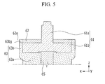
FIG. 5 is a cross-sectional view illustrating an electrode terminal of the rechargeable battery taken along line V-V ofFIG. 1 . -
FIG. 6 is a partial enlarged view illustrating a fastening state between an electrode terminal and a bus bar of a rechargeable battery according to a first exemplary embodiment of the present invention. -
FIG. 7 is a partial enlarged view illustrating a fastening state between an electrode terminal and a bus bar of a rechargeable battery according to an exemplary variation of the present invention. -
FIG. 8 is a partial exploded perspective view illustrating an electrode terminal of a rechargeable battery according to a second exemplary embodiment of the present invention. -
FIG. 9 is a cross-sectional view illustrating a rechargeable battery according to a third exemplary embodiment of the present invention. - In the following detailed description, only certain exemplary embodiments of the present invention are shown and described, simply by way of illustration. Accordingly, the drawings and description are to be regarded as illustrative in nature and not restrictive. Like reference numerals designate like elements throughout the specification.
- Throughout this specification and the claims that follow, when it is described that an element is "coupled" to another element, the element may be "directly coupled" to the other element or "electrically coupled" to the other element through a third element.
-
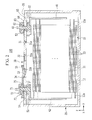
FIG. 1 is a perspective view illustrating a rechargeable battery according to a first exemplary embodiment of the present invention, andFIG. 2 is a cross-sectional view of the rechargeable battery taken along line II-II ofFIG. 1 . - Referring to
FIGS. 1 and2 , arechargeable battery 100 according to the present exemplary embodiment includes anelectrode assembly 10, acase 20 that houses theelectrode assembly 10, and acap assembly 30 that covers an opening of thecase 20. - The
electrode assembly 10 includes apositive electrode 11, anegative electrode 12, and aseparator 13, which is an insulator that is interposed between thepositive electrode 11 and thenegative electrode 12, and is formed in a jelly-roll shape by winding them. However, theelectrode assembly 10 is not limited thereto and may be formed in a stack structure in which multiple positive electrodes, separators, and negative electrodes that are formed as sheets are stacked. - The
positive electrode 11 and thenegative electrode 12 include coating portions, which are areas where an active material is coated on thin plates that function as current collectors, and uncoatedportions uncoated portion 11 a of thepositive electrode 11 is formed at one side end of thepositive electrode 11 along a length direction (y-axis direction) of thepositive electrode 11, and theuncoated portion 12a of thenegative electrode 12 is formed at the other side end of thenegative electrode 12 along a length direction (y-axis direction) of thenegative electrode 12. - The
case 20 is formed in an approximately rectangular parallelepiped shape having an empty center in order to form a space that houses theelectrode assembly 10 therein, and an opening that communicates with the internal space thereof is formed at one side of thecase 20. - The
cap assembly 30 includes acap plate 35 that is formed as a thin plate to cover an opening that is formed at one side of thecase 20. Further, thecap assembly 30 includes aseal stopper 31 and avent plate 32, and theseal stopper 31 and thevent plate 32 are formed in thecap plate 35 and are installed in an electrolytesolution injection port 31 a for injecting an electrolyte solution to the internal space of thecase 20 and avent hole 32a, respectively, for discharging gas generating within thecase 20. In this case, a notch to be opened when the internal pressure of therechargeable battery 100 arrives in a predetermined pressure is formed in thevent plate 32. Thecap assembly 30 according to the present exemplary embodiment includes adeformable member 33 and ashort circuit tab 34 for preventing explosion and ignition due to the increase of internal pressure of therechargeable battery 100, and this will be described again later. -
Electrode terminals cap plate 35, and are electrically connected to theelectrode assembly 10 to form an electrical passage between theelectrode assembly 10 and external constituent elements. In the present exemplary embodiment, thepositive terminal 60 includes afirst terminal plate 63, asecond terminal plate 62, a positiveterminal connection member 65, and a positiveterminal fastening member 61, and thenegative terminal 70 includes afirst terminal plate 73, asecond terminal plate 72, a negativeterminal connection member 75, and a negativeterminal fastening member 71. - Throughout the following, for ease of understanding, a first
terminal plate lower terminal plate second terminal plate upper terminal plate - The positive
uncoated portion 11 a and the negativeuncoated portion 12a of theelectrode assembly 10 are connected to apositive lead tab 41 and anegative lead tab 42, respectively, and thepositive lead tab 41 and thenegative lead tab 42 are connected to thepositive terminal 60 and thenegative terminal 70, respectively. The positiveterminal connection member 65 and the negativeterminal connection member 75 are each installed to penetrate thecap plate 35 to connect thepositive lead tab 41 and thelower terminal plate 63 of thepositive terminal 60 and connect thenegative lead tab 42 and thelower terminal plate 73 of thenegative terminal 70. Further, thelower terminal plate 63 of thepositive terminal 60 and thelower terminal plate 73 of thenegative terminal 70 are connected to theupper terminal plate 62 of thepositive terminal 60 and theupper terminal plate 72 of thenegative terminal 70, respectively. A detailed configuration of theelectrode terminals -
Lower insulation members terminal connection members lead tabs electrode assembly 10 from thecase 20 and thecap plate 35. Thelower insulation members negative lead tabs cap plate 35, and are formed to enclose a periphery of the positive andnegative lead tabs lower insulation members terminal connection members cap plate 35. By such a configuration, while thelead tabs terminal connection members lead tabs terminal connection members case 20 and thecap plate 35. -
Gaskets cap plate 35 and the positive and negativeterminal connection members cap plate 35 and seal the space between the positive and negativeterminal connection members cap plate 35, respectively. Further, thegaskets terminal connection members cap plate 35. - At the
positive terminal 60 side, aconnection plate 64 is installed between thelower terminal plate 63 and thecap plate 35. A through hole 64h is formed in theconnection plate 64 and the positiveterminal connection member 65 is connected to thelower terminal plate 63 by penetrating the through hole 64h. The positiveterminal connection member 65 is preferably formed in a rivet shape to be coupled as a rivet to thelower terminal plate 63. Accordingly, theconnection plate 64 is formed with material having excellent electrical conductivity such as aluminum and copper and closely contacts with thecap plate 35 by the configuration to electrically connect thepositive terminal 60 and thecap plate 35. - As described above, the
cap assembly 30 according to the present exemplary embodiment includes adeformable member 33 and ashort circuit tab 34. Thedeformable member 33 is installed in ashort circuit hole 33a that is formed in thecap plate 35 to be electrically connected to thecap plate 35, and theshort circuit tab 34 is formed to cover theshort circuit hole 33a to be electrically connected to thenegative terminal 70. Anupper insulation member 55 is installed between theshort circuit tab 34 and thecap plate 35 to insulate therebetween. - The
deformable member 33 is formed to bend toward the internal space of thecase 20, and if the internal pressure of therechargeable battery 100 arrives at a predetermined pressure by rising upon overcharging, thedeformable member 33 is deformed in a bent formation to the outside from the internal space of thecase 20 to contact theshort circuit tab 34. Therefore, when the internal pressure rises and arrives at a predetermined pressure, thedeformable member 33 and theshort circuit tab 34 are connected and thus a short circuit occurs and an overcharge is thus solved, thereby preventing explosion and ignition of therechargeable battery 100 due to the increase of internal pressure. Thedeformable member 33 is formed to have sufficient thickness to sustain a short circuit state even with regard to heat that is generated upon short-circuiting. - Hereinafter, a structure of an electrode terminal of a rechargeable battery according to a first exemplary embodiment of the present invention will be described in detail with reference to
FIGS. 3 to 5 . -
FIG. 3 is a partial exploded perspective view illustrating an electrode terminal of a rechargeable battery according to a first exemplary embodiment of the present invention,FIG. 4 is a cross-sectional view illustrating an electrode terminal of the rechargeable battery taken along line IV-IV ofFIG. 1 , andFIG. 5 is a cross-sectional view illustrating an electrode terminal of the rechargeable battery taken along line V-V ofFIG. 1 .FIGS. 3 to 5 illustrate only thepositive terminal 60 according to the present exemplary embodiment, and thenegative terminal 70 has a structure similar to that of thepositive terminal 60, thus thepositive terminal 60 will be described hereinafter, and portions of thenegative terminal 70 that are different from thepositive terminal 60 will be briefly described. - Referring to
FIGS. 3 to 5 , thepositive terminal 60 of therechargeable battery 100 according to the present exemplary embodiment includes anupper terminal plate 62, alower terminal plate 63, a positiveterminal connection member 65, and a positiveterminal fastening member 61. - As described above, the positive
terminal connection member 65 penetrates through holes that are formed in each of thecap plate 35 and theconnection plate 64, protrudes to the outside of thecap assembly 30, and is coupled to thelower terminal plate 63, preferably as a rivet. Thelower terminal plate 63 includes a pair ofside walls 63b that are formed at both sides extending along the y-axis inFig. 3 , and the positiveterminal fastening member 61 is housed in a space that is formed between the side walls 63b. Said space extends in the x-direction inFig. 1 , i.e. perpendicular to the direction of extension of theside walls 63b. Theupper terminal plate 62 is coupled to thelower terminal plate 63 while covering the positiveterminal fastening member 61 to fix the positiveterminal fastening member 61. - The
lower terminal plate 63 of thepositive terminal 60 includes abase plate 63a in which a throughhole 63h that has the positiveterminal connection member 65 inserted therein is formed, and a pair ofside walls 63b that are formed opposite to each other to be symmetrically arranged to the throughhole 63h along a width direction, i.e. the x-axis direction inFig. 3 , of thecap plate 35. Theside walls 63b extend in a length direction, the y-axis inFig. 3 . Thebase plate 63a is coupled by the rivet form of the positiveterminal connection member 65 to the positiveterminal connection member 65 to closely connect with theconnection plate 64, and the spaced apart pair ofside walls 63b form a space therebetween for housing the positiveterminal fastening member 61. In other words, the space between theside walls 63b in a width direction is equal to the width of the positiveterminal fastening member 61. - First groove portions 63ag are formed at both longitudinal sides of the
base plate 63a where theside walls 63b are not formed, i.e. spaced apart in a length or y-direction, and thus protrusions 61 bp that are formed in the positiveterminal fastening member 61, preferably at the sides of the positiveterminal fastening member 61 protruding downwards in a z-direction, are inserted into the first groove portions 63ag. Thus, the first groove portions 63ag and theprotrusions 61 bp are formed at corresponding locations with corresponding sizes to fit into each other. Further, a second groove portion 63bg is formed in the eachside wall 63b, preferably the top of eachside wall 63b has a second groove portion 63bg extending along theside wall 63b in the y-direction inFig. 3 . Anedge portion 62e of theupper terminal plate 62 is formed such that it fits into the second groove portion 63bg. In other words, theedge 62e of theupper terminal plate 62 has a size matching the extension of the second groove portion 63bg in the top ends of theside walls 63b of the firstterminal plate 63. In this way, by forming a first and second groove portions 63ag, 63bg to be coupled to the positiveterminal fastening member 61 and theupper terminal plate 62 in thelower terminal plate 63, they can be easily assembled, and after they are assembled, rotation and movement of the positiveterminal fastening member 61 and theupper terminal plate 62 are suppressed. In other words, theside walls 63b of thelower terminal plate 63 prevent movement of the positiveterminal fastening member 61 in an x-direction, the first groove portions 63ag along with theprotrusions 61 bp prevent movement the positiveterminal fastening member 61 in an x- and y-direction and the provision of the positiveterminal fastening member 61 sandwiched between the lower and theupper terminal plate terminal fastening member 61 in a vertical or z-direction. Due to the formation of the second groove portions 63bg on theside walls 63b of thelower terminal plate 63 and the fitting of theedges 62e of theupper terminal plate 62 into the second groove portions 63bg, theupper terminal plate 62 is prevented from moving in an x- and a y-direction. Theupper terminal plate 62 has the shape of a plate with cut-out corners. In other words, anedge 62e of theupper terminal plate 62 is a side end of theupper terminal plate 62 between two cut-out corners. - The position and size of groove portions 63ag, 63bg that are formed in the
base plate 63a and theside walls 63b are not limited to the illustrated example, and can be variously changed. - The
lower terminal plate 73 of thenegative terminal 70 has a structure similar to thelower terminal plate 63 of thepositive terminal 60. However, theshort circuit tab 34 and theupper insulation member 55 rather than theconnection plate 64 are installed between thelower terminal plate 73 and thecap plate 35, and through holes are formed in each of theshort circuit tab 34 and theupper insulation member 55 and thus the negativeterminal connection member 75 and thelower terminal plate 73 are coupled by the rivet form of the negative terminal connection member protruding 75 through the through holes. - The positive
terminal fastening member 61 includes aninsertion portion 61 b that is housed in thelower terminal plate 63 between the side walls of thelower terminal plate 63 and afastening portion 61 a that protrudes from one side of theinsertion portion 61 b. Theinsertion portion 61 b extends in a lateral plane while thefastening portion 61 a extends perpendicularly upward from theinsertion portion 61 b. Theinsertion portion 61 b has the same width as a distance between a pair ofside walls 63b of thelower terminal plate 63. Further, theinsertion portion 61 b includes aprotrusion 61 bp that is formed to correspond in size and location to the first groove portion 63ag that is formed in thebase plate 63a of thelower terminal plate 63. Referring toFIG. 4 , aprotrusion 61 bp that is formed in theinsertion portion 61 b is inserted into the first groove portion 63ag that is formed in thebase plate 63a of thelower terminal plate 63 to prevent the positiveterminal fastening member 61 from moving and rotating in x-axis and y-axis directions. - The
fastening portion 61 a protrudes to an opposite side of the side of theterminal fastening member 61 contacting thelower terminal plate 63. When a plurality ofrechargeable batteries 100 are formed in a battery module, neighboring rechargeable batteries are connected by a bus bar, and a thread is formed in thefastening portion 61 a of the positiveterminal fastening member 61 and by fastening and fixing the bus bar to the bar fastening member, theelectrode terminals - An upper part of the
upper terminal plate 62 is formed as a flat plate, and in order to insert thefastening portion 61 a of the positiveterminal fastening member 61, a throughhole 62h is formed in a central part of theupper terminal plate 62. Anedge portion 62e that protrudes to both sides (x-axis direction) of theupper terminal plate 62 to correspond in size and location to the second groove portion 63bg that is formed in the eachside wall 63b of thelower terminal plate 63 is formed in theupper terminal plate 62. Referring toFIGS. 4 and5 , while theupper terminal plate 62 is disposed to cover theinsertion portion 61 b of the positiveterminal fastening member 61, theedge 62e that is formed at both surfaces of theupper terminal plate 62 is welded by a laser after being inserted into the second groove portion 63bg that is formed in the eachside wall 63b of thelower terminal plate 63. - In this way, the
upper terminal plate 62 and thelower terminal plate 63 are connected by welding a contact portion thereof and thus rotation and movement of theupper terminal plate 62 in x-axis and y-axis directions is suppressed. Accordingly, while theupper terminal plate 62 and thelower terminal plate 63 are electrically connected, the positiveterminal fastening member 61 that is housed in thelower terminal plate 63 is stably fixed. - In other words, the lower surface of the
insertion portion 61 b directly contacts an upper surface of the base plate and is supported thereon and the upper surface of the insertion portion directly contacts a lower surface of the second terminal plate. Theinsertion portion 61 b has the same width as a distance between the at least twoside walls 63b of the firstterminal plate 63. Moreover, it has the same height as the vertical space formed between the first and secondterminal plates - In the present exemplary embodiment, the
upper terminal plate 62 and thelower terminal plate 63 are formed with a material having high electrical conductivity such as aluminum and copper, and the positiveterminal fastening member 61 is formed with a material having excellent strength such as stainless steel. - Because stainless steel has lower electrical conductivity than aluminum or copper, a current flowing to the
electrode assembly 10, thelead tab 41, and the positiveterminal connection member 65 does not flow through the positiveterminal fastening member 61 and is transferred to theupper terminal plate 62 via thelower terminal plate 63 to be connected to an external constituent element. - However, because stainless steel has a relatively larger strength than aluminum or copper, even if a large torque is applied when connecting a bus bar using a bus bar fastening member such as a nut to the positive
terminal fastening member 61 that is formed with stainless steel, the fastening portion is not deformed or damaged. - It is pointed out that it is not easy to directly connect the positive
terminal fastening member 61 that is formed with stainless steel, etc., having excellent strength to thelower terminal plate 63, theconnection plate 64, theshort circuit tab 34, or thecap plate 35 that is formed with aluminum or copper through welding, etc. However, as described above, in the present exemplary embodiment, thepositive terminal 60 includes theupper terminal plate 62 and thelower terminal plate 63, and by welding and securely connecting them, the positiveterminal fastening member 61 can be fixed to the space in which they are formed. -
FIG. 6 is a partial enlarged view illustrating a fastening state between an electrode terminal and a bus bar of a rechargeable battery according to a first exemplary embodiment of the present invention. - Referring to
FIG. 6 , when forming a battery module by arranging rechargeable batteries in a line, abus bar 80 is used for connectingelectrode terminals electrode terminals bus bar 80. - The
bus bar 80 is formed in a bar shape, and has a pair of terminal holes into which fastening portions of terminal fastening members of theelectrode terminals FIG. 6 , after thepositive terminal 60 and thenegative terminal 70 of a pair of neighboring rechargeable batteries are inserted into terminal holes that are formed in thebus bar 80 of a bar shape, thepositive terminal 60 and thenegative terminal 70 are fastened through busbar fastening members 85. Threads are formed in fastening portions of terminal fastening members of theelectrode terminals bus bar 80 to the thread, the busbar fastening member 85 is formed as a nut having a thread in an inside surface thereof. - As described above, the terminal fastening members of the
electrode terminals bar fastening member 85 to the terminal fastening member, a large torque can be applied. For example, when the terminal fastening member is formed with aluminum, upon fastening the bus bar fastening member, if a large torque is applied, the terminal fastening member may be deformed or damaged due to the low strength of aluminum. However, when forming the terminal fastening member with stainless steel, a torque of more than about double can be applied than when forming the terminal fastening member with aluminum. - In this way, by forming the terminal fastening member of the
electrode terminals bus bar 80, a torque that is applied to the busbar fastening member 85 can be large. Further, a terminal fastening member formed of a material different from that of a lower terminal plate and an upper terminal plate can be fixed through the lower terminal plate and the upper terminal plate, forming an electrical passage. Accordingly, even when using a battery module in an environment in which vibration and an impact frequently occur, such as in an electric vehicle or a hybrid vehicle, the connection between rechargeable batteries is suppressed from being released, and thus stability can be secured. - Further, as the upper surface of the
upper terminal plate 62 that functions as an electrical passage is formed flat, when forming a battery module, the contact area between thebus bar 80 and theelectrode terminals bus bar 80 and theelectrode terminals -
FIG. 7 is a partial enlarged view illustrating a fastening state between an electrode terminal and a bus bar of a rechargeable battery according to an exemplary variation of the present invention. - Referring to
FIG. 7 , in the present exemplary variation, when forming a battery module by arranging rechargeable batteries in a line, four rechargeable batteries are connected using one bus bar 80'. That is, two rechargeable batteries are disposed so that neighboring electrode terminals have the same polarity, for examplepositive terminals 60, and two rechargeable batteries are adjacently disposed so that positions of the above two rechargeable batteries and the electrode terminals are switched, and then four electrode terminals are connected by one bus bar. - A configuration for connecting four or more electrode terminals using one bus bar with a method similar to the present exemplary variation may be formed. When connecting rechargeable batteries with such a configuration, by connecting a plurality of rechargeable batteries by mixing a series connection and a parallel connection, a high capacity battery module can be formed.
- Hereinafter, another exemplary embodiment of the present invention will be described. When describing this exemplary embodiment, the same configurations as of the first exemplary embodiment will be briefly described, or a description thereof will be omitted.
-
FIG. 8 is a partial exploded perspective view illustrating an electrode terminal of a rechargeable battery according to a second exemplary embodiment of the present invention.FIG. 8 illustrates only apositive terminal 160 according to the present exemplary embodiment, and a negative terminal has a structure similar to thepositive terminal 160 and thus a description of the negative terminal will be omitted hereinafter. - In the present exemplary embodiment, other elements of a
rechargeable battery 200 except for the electrode terminal are to the same as those of the first exemplary embodiment. That is, therechargeable battery 200 of the present exemplary embodiment includes an electrode assembly including a positive electrode, a negative electrode, and a separator, a case that houses the electrode assembly, and a cap assembly including a cap plate that covers an opening that is formed at one side of the case. However, in the present exemplary embodiment, the structure of an electrode terminal is different from that of the first exemplary embodiment, and will be described hereinafter. - Referring to
FIG. 8 , thepositive terminal 160 according to the present exemplary embodiment includes anupper terminal plate 162, alower terminal plate 163, a positiveterminal connection member 165, and a positiveterminal fastening member 161. - The positive
terminal connection member 165 penetrates through holes that are formed in each of a cap plate and aconnection plate 164, protrudes to the outside of the cap assembly, and is coupled as a rivet to thelower terminal plate 163. Thelower terminal plate 163 includes abase plate 163a andside walls 163b, and houses aninsertion portion 161b of the positiveterminal fastening member 161 within a space that is enclosed by theside walls 163b. - The upper
terminal plate 162 is coupled to thelower terminal plate 163 while covering theinsertion portion 161b of the positiveterminal fastening member 161. Specifically, groove portions 163bg are formed in theside walls 163b of thelower terminal plate 163,edge portions 162e of the upperterminal plate 162 are inserted into and coupled to the groove portions 163bg, and by performing laser welding along coupling portions, the upperterminal plate 162 and thelower terminal plate 163 are fixed. Afastening portion 161 a of the positiveterminal fastening member 161 protrudes to an opposite side that contacts thelower terminal plate 163. - In this way, in the present exemplary embodiment, the
side walls 163b are formed along the whole circumference of thebase plate 163a and thus the positiveterminal fastening member 161 is housed inside the space formed by theside walls 163b, and the upperterminal plate 162 is coupled and fixed to thelower terminal plate 163. Accordingly, the positiveterminal fastening member 161 can be stably fixed without forming a separate groove portion in thebase plate 163a of thelower terminal plate 163. In other words, in contrast to the embodiment ofFig. 3 , theside walls 63b are formed on each of the four sides of thelower terminal plate 63, theside walls 63b being connected to each other forming a closed structure along the whole circumference of thebase plate 163a. -
FIG. 9 is a cross-sectional view illustrating a rechargeable battery according to a third exemplary embodiment of the present invention. - Referring to
FIG. 9 , arechargeable battery 300 according to the present exemplary embodiment has a similar structure to that of therechargeable battery 100 according to the first exemplary embodiment. That is, therechargeable battery 300 includes anelectrode assembly 10 including apositive electrode 11, anegative electrode 12, and aseparator 13, acase 20 that houses theelectrode assembly 10, acap assembly 30 including acap plate 35 that covers an opening that is formed at one side of thecase 20, andelectrode terminals cap plate 35. Further, theelectrode terminals terminal plates terminal plates terminal connection members terminal fastening members - In the
cap assembly 30 of the present exemplary embodiment, a deformable member of the first exemplary embodiment is not formed. Accordingly, in a lower part of thelower terminal plate 263 of thepositive terminal 260, a connection plate that is electrically connected to thecap plate 35 is not formed, and in a lower part of thelower terminal plate 273 of thenegative terminal 270, a short circuit tab and an upper insulation member are not formed. In the present exemplary embodiment,gaskets upper gaskets lower gaskets terminal connection members cap plate 35 and insulating the lowerterminal plates cap plate 35. - Accordingly, a fastening force between neighboring electrode terminals can be improved with a simple structure in which a deformable member is omitted according to a use and process of a rechargeable battery.
Claims (15)
- A rechargeable battery comprising:an electrode assembly (10),a case (20) for housing the electrode assembly (10) therein,a cap plate (35) covering an opening of the case (20),an electrode terminal (60, 70) connected to the electrode assembly (10) comprising:a first terminal plate (63) located on the cap plate (35) and electrically coupled to the electrode assembly (10), anda second terminal plate (62) electrically coupled to the first terminal plate (63) and having a through-hole (62h) formed therein,characterized in thata terminal fastening member (61) is provided comprising an insertion portion (61 b) fitted between the first and second terminal plates (62, 63) and a fastening portion (61 a) protruding through the through-hole (62h) in the second terminal plate (62).
- Rechargeable battery of claim 1, chargeable battery of any of the previous claims,
wherein the terminal fastening member (61) is formed of a material being different from and having greater strength than the materials of the first and second terminal plates (63, 62). - Rechargeable battery of claim 1 or 2, wherein the terminal fastening member (61) is formed of a material having a lower electrical conductivity than the materials of the first and second terminal plates (63, 62).
- Rechargeable battery of one of the previous claims, wherein the first and second terminal plates (63, 62) are formed of the same material, preferably of aluminium or copper, and the terminal fastening member (61) is formed of stainless steel.
- Rechargeable battery of one of the previous claims, wherein the first and second terminal plates (63, 62) are separate plates being welded to each other.
- Rechargeable battery of one of the previous claims, wherein the terminal fastening member is framed or bound by the first and second terminal plates (63, 62) at least in a vertical direction (z).
- Rechargeable battery of one of the previous claims, wherein the first terminal plate (63) comprises a base plate (63a) and at least two side walls (63b) extending from the base plate (63a).
- Rechargeable battery of claims 7, wherein the lower surface of the insertion portion (61 b) directly contacts an upper surface of the base plate (63a) and is supported thereon and the upper surface of the insertion portion (61 b) directly contacts a lower surface of the second terminal plate (62).
- Rechargeable battery of one of claims 7 or 8, wherein the insertion portion (61 b) has the same width as a distance between the at least two side walls (63b) of the first terminal plate (63) and/or the same height as the vertical space formed between the first and second terminal plates (63, 62).
- Rechargeable battery of one of claims 7 to 9, wherein first groove portions (63ag) are formed on the base plate (63a) and first protrusions (61 bp) are formed on the terminal fastening member (61) adapted to fit into the first groove portions (63ag).
- Rechargeable battery of one of claims 7 to 10, wherein a second groove portion (63bg) is formed on a side wall (63b) of the first terminal plate (63) adapted to receive an edge of the second terminal plate (62).
- Rechargeable battery of claim 11, wherein an edge (62e) of the second terminal plate (62) is welded to the first terminal plate (63) at a location corresponding to the second groove portion (63bg).
- Rechargeable battery of one of the previous claims, wherein a connection plate (64) is provided between the first terminal plate (63) and the cap plate (20), the connection plate (64) electrically coupling the cap plate (20) to the first terminal plate (63).
- Rechargeable battery of claims 13, wherein the first terminal plate (63) and the connection plate (64) each comprise through-holes, for inserting a terminal connection member (65) therein, the terminal connection member (65) extending from an inside of the case (20).
- Battery module comprising:a plurality of rechargeable batteries according to on of claims 1 to 14, anda bus bar (80) which electrically couples an electrode terminal (60, 70) of a first rechargeable battery with an electrode terminal (60, 70) of a second rechargeable battery,and is arranged between a second terminal plate (63) of a respective terminal (60, 70) and a bus bar fastening member (85),wherein the bus bar fastening member (85) is fixed to the terminal fastening member (61) of the respective terminal (60, 70).
Applications Claiming Priority (2)
| Application Number | Priority Date | Filing Date | Title |
|---|---|---|---|
| US37405910P | 2010-08-16 | 2010-08-16 | |
| US12/965,739 US8916287B2 (en) | 2010-08-16 | 2010-12-10 | Rechargeable battery |
Publications (2)
| Publication Number | Publication Date |
|---|---|
| EP2421065A1 true EP2421065A1 (en) | 2012-02-22 |
| EP2421065B1 EP2421065B1 (en) | 2013-11-06 |
Family
ID=44710050
Family Applications (1)
| Application Number | Title | Priority Date | Filing Date |
|---|---|---|---|
| EP11162791.5A Active EP2421065B1 (en) | 2010-08-16 | 2011-04-18 | Rechargeable battery |
Country Status (5)
| Country | Link |
|---|---|
| US (1) | US8916287B2 (en) |
| EP (1) | EP2421065B1 (en) |
| JP (1) | JP5345648B2 (en) |
| KR (1) | KR101223568B1 (en) |
| CN (1) | CN102376931B (en) |
Cited By (1)
| Publication number | Priority date | Publication date | Assignee | Title |
|---|---|---|---|---|
| WO2013023760A3 (en) * | 2011-08-17 | 2013-08-01 | Li-Tec Battery Gmbh | Method for producing an electrochemical cell, electrochemical cell, and energy storage device having at least two electrochemical cells |
Families Citing this family (39)
| Publication number | Priority date | Publication date | Assignee | Title |
|---|---|---|---|---|
| KR101136219B1 (en) * | 2010-06-09 | 2012-04-17 | 에스비리모티브 주식회사 | Secondary battery and method for fabricating the same |
| KR101223521B1 (en) * | 2010-08-16 | 2013-01-17 | 로베르트 보쉬 게엠베하 | Rechargeable battery |
| JP5541015B2 (en) * | 2010-09-08 | 2014-07-09 | 株式会社Gsユアサ | Power storage device |
| JP5533479B2 (en) * | 2010-09-14 | 2014-06-25 | 株式会社Gsユアサ | Power storage device and method for manufacturing power storage device |
| US8309246B2 (en) * | 2010-10-25 | 2012-11-13 | Sb Limotive Co., Ltd. | Terminal of rechargeable battery and method of manufacturing the same |
| US20120177978A1 (en) * | 2011-01-11 | 2012-07-12 | Sungbae Kim | Secondary battery, method of assembling the same, and battery pack including the secondary battery |
| US9023498B2 (en) * | 2011-07-07 | 2015-05-05 | Samsung Sdi Co., Ltd. | Rechargeable battery |
| US8592079B2 (en) * | 2011-07-28 | 2013-11-26 | Samsung Sdi Co., Ltd. | Rechargeable battery |
| JP2013055020A (en) * | 2011-09-06 | 2013-03-21 | Toshiba Corp | Battery and battery pack |
| KR101666876B1 (en) * | 2011-10-12 | 2016-10-25 | 삼성에스디아이 주식회사 | Rechargeable battery and module thereof |
| KR20130040576A (en) * | 2011-10-14 | 2013-04-24 | 삼성에스디아이 주식회사 | Rechargeable battery |
| KR101666870B1 (en) * | 2012-03-20 | 2016-10-17 | 삼성에스디아이 주식회사 | Rechargeable battery including resistance member |
| WO2013190969A1 (en) * | 2012-06-20 | 2013-12-27 | 株式会社Gsユアサ | Fastening structure |
| DE102012213273B4 (en) * | 2012-07-27 | 2021-08-05 | Hydac Technology Gmbh | Energy storage device |
| JP6119139B2 (en) * | 2012-07-30 | 2017-04-26 | 株式会社Gsユアサ | Storage element and power supply module |
| KR101698767B1 (en) * | 2013-01-28 | 2017-01-23 | 삼성에스디아이 주식회사 | Secondary battery |
| KR101724013B1 (en) * | 2013-09-24 | 2017-04-06 | 삼성에스디아이 주식회사 | Rechargeable battery |
| JP2015099647A (en) * | 2013-11-18 | 2015-05-28 | 本田技研工業株式会社 | Power storage module and power storage cell |
| JP6149719B2 (en) * | 2013-12-17 | 2017-06-21 | 住友電気工業株式会社 | Molten salt battery |
| JP5761394B2 (en) * | 2014-01-30 | 2015-08-12 | 株式会社豊田自動織機 | Electrode terminal, power storage device, and power storage module |
| KR102154332B1 (en) * | 2014-02-27 | 2020-09-09 | 삼성에스디아이 주식회사 | Secondary Battery |
| KR102337570B1 (en) * | 2015-02-24 | 2021-12-08 | 삼성에스디아이 주식회사 | Rechargeable battery |
| KR102416528B1 (en) | 2015-04-06 | 2022-07-01 | 삼성에스디아이 주식회사 | Rechargeable battery |
| KR102356939B1 (en) * | 2015-04-27 | 2022-01-28 | 삼성에스디아이 주식회사 | Battery module |
| KR102371192B1 (en) * | 2015-08-07 | 2022-03-07 | 삼성에스디아이 주식회사 | A secondary battery |
| US10388933B2 (en) * | 2016-08-08 | 2019-08-20 | Gs Yuasa International Ltd. | Energy storage apparatus |
| CN106058115A (en) * | 2016-08-16 | 2016-10-26 | 上海中兴派能能源科技有限公司 | Flexible package lithium battery module structure |
| WO2018061971A1 (en) * | 2016-09-30 | 2018-04-05 | ブラザー工業株式会社 | Battery |
| CN114976401B (en) | 2017-08-30 | 2024-03-29 | 宁德时代新能源科技股份有限公司 | Top cap subassembly and secondary cell of secondary cell |
| CN109659453B (en) * | 2017-10-10 | 2020-09-15 | 宁德时代新能源科技股份有限公司 | Secondary cell's top cap subassembly and secondary cell |
| CN109659454B (en) * | 2017-10-10 | 2020-11-10 | 宁德时代新能源科技股份有限公司 | Secondary cell's top cap subassembly and secondary cell |
| CN109728208B (en) * | 2017-10-27 | 2021-09-14 | 宁德时代新能源科技股份有限公司 | Secondary cell's top cap subassembly, secondary cell and battery module |
| KR102106446B1 (en) * | 2017-12-08 | 2020-05-04 | 삼성에스디아이 주식회사 | Battery module |
| JP7064695B2 (en) * | 2017-12-15 | 2022-05-11 | トヨタ自動車株式会社 | Sealed battery, assembled battery, manufacturing method of sealed battery and manufacturing method of assembled battery |
| CN110224104B (en) * | 2018-03-02 | 2021-07-09 | 比亚迪股份有限公司 | Negative pole post of battery, apron subassembly of battery, battery and electric automobile |
| CN208873925U (en) * | 2018-08-23 | 2019-05-17 | 泰科电子(上海)有限公司 | Electrical connection module |
| JP7368080B2 (en) * | 2018-08-31 | 2023-10-24 | 三洋電機株式会社 | secondary battery |
| CN113067087B (en) * | 2019-12-31 | 2022-08-09 | 比亚迪股份有限公司 | Battery pack and vehicle with same |
| US11749931B2 (en) * | 2021-12-21 | 2023-09-05 | GM Global Technology Operations LLC | Electrical connection unit for high-voltage battery packs |
Citations (6)
| Publication number | Priority date | Publication date | Assignee | Title |
|---|---|---|---|---|
| JPH11195434A (en) * | 1997-10-07 | 1999-07-21 | Matsushita Electric Ind Co Ltd | Nonaqueous electrolyte secondary battery |
| JP2001357834A (en) * | 2000-06-16 | 2001-12-26 | Japan Storage Battery Co Ltd | Battery |
| JP2008097903A (en) * | 2006-10-10 | 2008-04-24 | Yazaki Corp | Connection terminal |
| JP2009259424A (en) * | 2008-04-11 | 2009-11-05 | Toyota Motor Corp | Battery, battery pack, vehicle, and battery-mounted apparatus |
| JP2010055786A (en) * | 2008-08-26 | 2010-03-11 | Toyota Motor Corp | Battery and battery pack |
| US20100143786A1 (en) * | 2008-12-08 | 2010-06-10 | Samsung Sdi Co., Ltd. | Rechargeable battery and battery module using the same |
Family Cites Families (6)
| Publication number | Priority date | Publication date | Assignee | Title |
|---|---|---|---|---|
| EP0964461B1 (en) | 1997-10-07 | 2007-04-11 | Matsushita Electric Industrial Co., Ltd. | Non-aqueous electrolyte secondary cell |
| JP3685723B2 (en) | 2001-03-02 | 2005-08-24 | 三洋電機株式会社 | Secondary battery |
| JP4614637B2 (en) | 2002-12-05 | 2011-01-19 | 矢崎総業株式会社 | Battery terminal |
| JP4974734B2 (en) | 2006-10-10 | 2012-07-11 | 三星エスディアイ株式会社 | Secondary battery and secondary battery module |
| JP2010033919A (en) | 2008-07-30 | 2010-02-12 | Yazaki Corp | Battery terminal |
| JP2010092697A (en) | 2008-10-07 | 2010-04-22 | Sumitomo Wiring Syst Ltd | Terminal connection structure to battery |
-
2010
- 2010-12-10 US US12/965,739 patent/US8916287B2/en active Active
- 2010-12-30 KR KR1020100139426A patent/KR101223568B1/en active IP Right Grant
-
2011
- 2011-04-07 JP JP2011085288A patent/JP5345648B2/en active Active
- 2011-04-18 EP EP11162791.5A patent/EP2421065B1/en active Active
- 2011-07-25 CN CN201110215204.3A patent/CN102376931B/en active Active
Patent Citations (6)
| Publication number | Priority date | Publication date | Assignee | Title |
|---|---|---|---|---|
| JPH11195434A (en) * | 1997-10-07 | 1999-07-21 | Matsushita Electric Ind Co Ltd | Nonaqueous electrolyte secondary battery |
| JP2001357834A (en) * | 2000-06-16 | 2001-12-26 | Japan Storage Battery Co Ltd | Battery |
| JP2008097903A (en) * | 2006-10-10 | 2008-04-24 | Yazaki Corp | Connection terminal |
| JP2009259424A (en) * | 2008-04-11 | 2009-11-05 | Toyota Motor Corp | Battery, battery pack, vehicle, and battery-mounted apparatus |
| JP2010055786A (en) * | 2008-08-26 | 2010-03-11 | Toyota Motor Corp | Battery and battery pack |
| US20100143786A1 (en) * | 2008-12-08 | 2010-06-10 | Samsung Sdi Co., Ltd. | Rechargeable battery and battery module using the same |
Cited By (1)
| Publication number | Priority date | Publication date | Assignee | Title |
|---|---|---|---|---|
| WO2013023760A3 (en) * | 2011-08-17 | 2013-08-01 | Li-Tec Battery Gmbh | Method for producing an electrochemical cell, electrochemical cell, and energy storage device having at least two electrochemical cells |
Also Published As
| Publication number | Publication date |
|---|---|
| US8916287B2 (en) | 2014-12-23 |
| CN102376931A (en) | 2012-03-14 |
| JP2012043771A (en) | 2012-03-01 |
| US20110244310A1 (en) | 2011-10-06 |
| KR20120016569A (en) | 2012-02-24 |
| CN102376931B (en) | 2015-03-25 |
| JP5345648B2 (en) | 2013-11-20 |
| EP2421065B1 (en) | 2013-11-06 |
| KR101223568B1 (en) | 2013-01-17 |
Similar Documents
| Publication | Publication Date | Title |
|---|---|---|
| EP2421065B1 (en) | Rechargeable battery | |
| US8795881B2 (en) | Terminal of rechargeable battery, method of assembling the terminal of rechargeable battery, rechargeable battery module and method of assembling the rechargeable battery module | |
| EP2675000B1 (en) | Rechargeable battery | |
| KR101201745B1 (en) | Rechargeable battery | |
| JP5208976B2 (en) | Battery module | |
| KR101155888B1 (en) | Rechargeable battery | |
| US8734974B2 (en) | Rechargeable battery | |
| KR101265202B1 (en) | Rechargeable battery | |
| KR101627631B1 (en) | Rechargeable battery and module thereof | |
| EP2043180B1 (en) | Rechargeable Battery | |
| US8592079B2 (en) | Rechargeable battery | |
| US8647759B2 (en) | Secondary battery | |
| CN106356490B (en) | Rechargeable battery and battery module including the same | |
| EP2475023B1 (en) | Battery and battery pack having the same | |
| CN109075304B (en) | Rechargeable battery with diaphragm | |
| EP2048723B1 (en) | Battery module | |
| CN105374955B (en) | Rechargeable battery with short-circuit protrusion | |
| KR101147172B1 (en) | Rechargeable battery and battery module | |
| CN109716573B (en) | Rechargeable battery, electrode assembly and method for manufacturing electrode assembly | |
| WO2023145586A1 (en) | Power storage device |
Legal Events
| Date | Code | Title | Description |
|---|---|---|---|
| AK | Designated contracting states |
Kind code of ref document: A1 Designated state(s): AL AT BE BG CH CY CZ DE DK EE ES FI FR GB GR HR HU IE IS IT LI LT LU LV MC MK MT NL NO PL PT RO RS SE SI SK SM TR |
|
| AX | Request for extension of the european patent |
Extension state: BA ME |
|
| PUAI | Public reference made under article 153(3) epc to a published international application that has entered the european phase |
Free format text: ORIGINAL CODE: 0009012 |
|
| 17P | Request for examination filed |
Effective date: 20120326 |
|
| REG | Reference to a national code |
Ref country code: DE Ref legal event code: R079 Ref document number: 602011003607 Country of ref document: DE Free format text: PREVIOUS MAIN CLASS: H01M0002040000 Ipc: H01M0002060000 |
|
| RIC1 | Information provided on ipc code assigned before grant |
Ipc: H01M 2/30 20060101ALI20120824BHEP Ipc: H01M 10/04 20060101ALI20120824BHEP Ipc: H01M 2/20 20060101ALI20120824BHEP Ipc: H01M 2/04 20060101ALI20120824BHEP Ipc: H01M 2/06 20060101AFI20120824BHEP Ipc: H01M 2/02 20060101ALI20120824BHEP Ipc: H01M 6/42 20060101ALI20120824BHEP |
|
| GRAP | Despatch of communication of intention to grant a patent |
Free format text: ORIGINAL CODE: EPIDOSNIGR1 |
|
| RAP1 | Party data changed (applicant data changed or rights of an application transferred) |
Owner name: SAMSUNG SDI CO., LTD. Owner name: ROBERT BOSCH GMBH |
|
| GRAP | Despatch of communication of intention to grant a patent |
Free format text: ORIGINAL CODE: EPIDOSNIGR1 |
|
| INTG | Intention to grant announced |
Effective date: 20130723 |
|
| GRAS | Grant fee paid |
Free format text: ORIGINAL CODE: EPIDOSNIGR3 |
|
| GRAA | (expected) grant |
Free format text: ORIGINAL CODE: 0009210 |
|
| AK | Designated contracting states |
Kind code of ref document: B1 Designated state(s): AL AT BE BG CH CY CZ DE DK EE ES FI FR GB GR HR HU IE IS IT LI LT LU LV MC MK MT NL NO PL PT RO RS SE SI SK SM TR |
|
| REG | Reference to a national code |
Ref country code: GB Ref legal event code: FG4D |
|
| REG | Reference to a national code |
Ref country code: CH Ref legal event code: EP |
|
| REG | Reference to a national code |
Ref country code: AT Ref legal event code: REF Ref document number: 639968 Country of ref document: AT Kind code of ref document: T Effective date: 20131215 |
|
| REG | Reference to a national code |
Ref country code: IE Ref legal event code: FG4D |
|
| REG | Reference to a national code |
Ref country code: DE Ref legal event code: R096 Ref document number: 602011003607 Country of ref document: DE Effective date: 20140213 |
|
| REG | Reference to a national code |
Ref country code: NL Ref legal event code: VDEP Effective date: 20131106 |
|
| REG | Reference to a national code |
Ref country code: AT Ref legal event code: MK05 Ref document number: 639968 Country of ref document: AT Kind code of ref document: T Effective date: 20131106 |
|
| REG | Reference to a national code |
Ref country code: LT Ref legal event code: MG4D |
|
| PG25 | Lapsed in a contracting state [announced via postgrant information from national office to epo] |
Ref country code: SE Free format text: LAPSE BECAUSE OF FAILURE TO SUBMIT A TRANSLATION OF THE DESCRIPTION OR TO PAY THE FEE WITHIN THE PRESCRIBED TIME-LIMIT Effective date: 20131106 Ref country code: NL Free format text: LAPSE BECAUSE OF FAILURE TO SUBMIT A TRANSLATION OF THE DESCRIPTION OR TO PAY THE FEE WITHIN THE PRESCRIBED TIME-LIMIT Effective date: 20131106 Ref country code: NO Free format text: LAPSE BECAUSE OF FAILURE TO SUBMIT A TRANSLATION OF THE DESCRIPTION OR TO PAY THE FEE WITHIN THE PRESCRIBED TIME-LIMIT Effective date: 20140206 Ref country code: LT Free format text: LAPSE BECAUSE OF FAILURE TO SUBMIT A TRANSLATION OF THE DESCRIPTION OR TO PAY THE FEE WITHIN THE PRESCRIBED TIME-LIMIT Effective date: 20131106 Ref country code: HR Free format text: LAPSE BECAUSE OF FAILURE TO SUBMIT A TRANSLATION OF THE DESCRIPTION OR TO PAY THE FEE WITHIN THE PRESCRIBED TIME-LIMIT Effective date: 20131106 Ref country code: FI Free format text: LAPSE BECAUSE OF FAILURE TO SUBMIT A TRANSLATION OF THE DESCRIPTION OR TO PAY THE FEE WITHIN THE PRESCRIBED TIME-LIMIT Effective date: 20131106 Ref country code: IS Free format text: LAPSE BECAUSE OF FAILURE TO SUBMIT A TRANSLATION OF THE DESCRIPTION OR TO PAY THE FEE WITHIN THE PRESCRIBED TIME-LIMIT Effective date: 20140306 |
|
| PG25 | Lapsed in a contracting state [announced via postgrant information from national office to epo] |
Ref country code: ES Free format text: LAPSE BECAUSE OF FAILURE TO SUBMIT A TRANSLATION OF THE DESCRIPTION OR TO PAY THE FEE WITHIN THE PRESCRIBED TIME-LIMIT Effective date: 20131106 Ref country code: LV Free format text: LAPSE BECAUSE OF FAILURE TO SUBMIT A TRANSLATION OF THE DESCRIPTION OR TO PAY THE FEE WITHIN THE PRESCRIBED TIME-LIMIT Effective date: 20131106 Ref country code: AT Free format text: LAPSE BECAUSE OF FAILURE TO SUBMIT A TRANSLATION OF THE DESCRIPTION OR TO PAY THE FEE WITHIN THE PRESCRIBED TIME-LIMIT Effective date: 20131106 Ref country code: BE Free format text: LAPSE BECAUSE OF FAILURE TO SUBMIT A TRANSLATION OF THE DESCRIPTION OR TO PAY THE FEE WITHIN THE PRESCRIBED TIME-LIMIT Effective date: 20131106 Ref country code: RS Free format text: LAPSE BECAUSE OF FAILURE TO SUBMIT A TRANSLATION OF THE DESCRIPTION OR TO PAY THE FEE WITHIN THE PRESCRIBED TIME-LIMIT Effective date: 20131106 |
|
| PG25 | Lapsed in a contracting state [announced via postgrant information from national office to epo] |
Ref country code: PT Free format text: LAPSE BECAUSE OF FAILURE TO SUBMIT A TRANSLATION OF THE DESCRIPTION OR TO PAY THE FEE WITHIN THE PRESCRIBED TIME-LIMIT Effective date: 20140306 |
|
| PG25 | Lapsed in a contracting state [announced via postgrant information from national office to epo] |
Ref country code: EE Free format text: LAPSE BECAUSE OF FAILURE TO SUBMIT A TRANSLATION OF THE DESCRIPTION OR TO PAY THE FEE WITHIN THE PRESCRIBED TIME-LIMIT Effective date: 20131106 |
|
| REG | Reference to a national code |
Ref country code: DE Ref legal event code: R097 Ref document number: 602011003607 Country of ref document: DE |
|
| PG25 | Lapsed in a contracting state [announced via postgrant information from national office to epo] |
Ref country code: SK Free format text: LAPSE BECAUSE OF FAILURE TO SUBMIT A TRANSLATION OF THE DESCRIPTION OR TO PAY THE FEE WITHIN THE PRESCRIBED TIME-LIMIT Effective date: 20131106 Ref country code: IT Free format text: LAPSE BECAUSE OF FAILURE TO SUBMIT A TRANSLATION OF THE DESCRIPTION OR TO PAY THE FEE WITHIN THE PRESCRIBED TIME-LIMIT Effective date: 20131106 Ref country code: PL Free format text: LAPSE BECAUSE OF FAILURE TO SUBMIT A TRANSLATION OF THE DESCRIPTION OR TO PAY THE FEE WITHIN THE PRESCRIBED TIME-LIMIT Effective date: 20131106 Ref country code: CZ Free format text: LAPSE BECAUSE OF FAILURE TO SUBMIT A TRANSLATION OF THE DESCRIPTION OR TO PAY THE FEE WITHIN THE PRESCRIBED TIME-LIMIT Effective date: 20131106 Ref country code: RO Free format text: LAPSE BECAUSE OF FAILURE TO SUBMIT A TRANSLATION OF THE DESCRIPTION OR TO PAY THE FEE WITHIN THE PRESCRIBED TIME-LIMIT Effective date: 20131106 |
|
| PLBE | No opposition filed within time limit |
Free format text: ORIGINAL CODE: 0009261 |
|
| STAA | Information on the status of an ep patent application or granted ep patent |
Free format text: STATUS: NO OPPOSITION FILED WITHIN TIME LIMIT |
|
| PG25 | Lapsed in a contracting state [announced via postgrant information from national office to epo] |
Ref country code: DK Free format text: LAPSE BECAUSE OF FAILURE TO SUBMIT A TRANSLATION OF THE DESCRIPTION OR TO PAY THE FEE WITHIN THE PRESCRIBED TIME-LIMIT Effective date: 20131106 |
|
| 26N | No opposition filed |
Effective date: 20140807 |
|
| REG | Reference to a national code |
Ref country code: DE Ref legal event code: R097 Ref document number: 602011003607 Country of ref document: DE Effective date: 20140807 |
|
| PG25 | Lapsed in a contracting state [announced via postgrant information from national office to epo] |
Ref country code: LU Free format text: LAPSE BECAUSE OF FAILURE TO SUBMIT A TRANSLATION OF THE DESCRIPTION OR TO PAY THE FEE WITHIN THE PRESCRIBED TIME-LIMIT Effective date: 20140418 Ref country code: MC Free format text: LAPSE BECAUSE OF FAILURE TO SUBMIT A TRANSLATION OF THE DESCRIPTION OR TO PAY THE FEE WITHIN THE PRESCRIBED TIME-LIMIT Effective date: 20131106 |
|
| REG | Reference to a national code |
Ref country code: CH Ref legal event code: PL |
|
| REG | Reference to a national code |
Ref country code: IE Ref legal event code: MM4A |
|
| PG25 | Lapsed in a contracting state [announced via postgrant information from national office to epo] |
Ref country code: LI Free format text: LAPSE BECAUSE OF NON-PAYMENT OF DUE FEES Effective date: 20140430 Ref country code: CH Free format text: LAPSE BECAUSE OF NON-PAYMENT OF DUE FEES Effective date: 20140430 |
|
| PG25 | Lapsed in a contracting state [announced via postgrant information from national office to epo] |
Ref country code: SI Free format text: LAPSE BECAUSE OF FAILURE TO SUBMIT A TRANSLATION OF THE DESCRIPTION OR TO PAY THE FEE WITHIN THE PRESCRIBED TIME-LIMIT Effective date: 20131106 |
|
| PG25 | Lapsed in a contracting state [announced via postgrant information from national office to epo] |
Ref country code: IE Free format text: LAPSE BECAUSE OF NON-PAYMENT OF DUE FEES Effective date: 20140418 |
|
| REG | Reference to a national code |
Ref country code: FR Ref legal event code: PLFP Year of fee payment: 6 |
|
| PG25 | Lapsed in a contracting state [announced via postgrant information from national office to epo] |
Ref country code: MT Free format text: LAPSE BECAUSE OF FAILURE TO SUBMIT A TRANSLATION OF THE DESCRIPTION OR TO PAY THE FEE WITHIN THE PRESCRIBED TIME-LIMIT Effective date: 20131106 |
|
| PG25 | Lapsed in a contracting state [announced via postgrant information from national office to epo] |
Ref country code: SM Free format text: LAPSE BECAUSE OF FAILURE TO SUBMIT A TRANSLATION OF THE DESCRIPTION OR TO PAY THE FEE WITHIN THE PRESCRIBED TIME-LIMIT Effective date: 20131106 |
|
| PG25 | Lapsed in a contracting state [announced via postgrant information from national office to epo] |
Ref country code: GR Free format text: LAPSE BECAUSE OF FAILURE TO SUBMIT A TRANSLATION OF THE DESCRIPTION OR TO PAY THE FEE WITHIN THE PRESCRIBED TIME-LIMIT Effective date: 20140207 Ref country code: BG Free format text: LAPSE BECAUSE OF FAILURE TO SUBMIT A TRANSLATION OF THE DESCRIPTION OR TO PAY THE FEE WITHIN THE PRESCRIBED TIME-LIMIT Effective date: 20131106 Ref country code: CY Free format text: LAPSE BECAUSE OF FAILURE TO SUBMIT A TRANSLATION OF THE DESCRIPTION OR TO PAY THE FEE WITHIN THE PRESCRIBED TIME-LIMIT Effective date: 20131106 |
|
| PG25 | Lapsed in a contracting state [announced via postgrant information from national office to epo] |
Ref country code: TR Free format text: LAPSE BECAUSE OF FAILURE TO SUBMIT A TRANSLATION OF THE DESCRIPTION OR TO PAY THE FEE WITHIN THE PRESCRIBED TIME-LIMIT Effective date: 20131106 Ref country code: HU Free format text: LAPSE BECAUSE OF FAILURE TO SUBMIT A TRANSLATION OF THE DESCRIPTION OR TO PAY THE FEE WITHIN THE PRESCRIBED TIME-LIMIT; INVALID AB INITIO Effective date: 20110418 |
|
| REG | Reference to a national code |
Ref country code: FR Ref legal event code: PLFP Year of fee payment: 7 |
|
| REG | Reference to a national code |
Ref country code: FR Ref legal event code: PLFP Year of fee payment: 8 |
|
| PG25 | Lapsed in a contracting state [announced via postgrant information from national office to epo] |
Ref country code: MK Free format text: LAPSE BECAUSE OF FAILURE TO SUBMIT A TRANSLATION OF THE DESCRIPTION OR TO PAY THE FEE WITHIN THE PRESCRIBED TIME-LIMIT Effective date: 20131106 |
|
| PG25 | Lapsed in a contracting state [announced via postgrant information from national office to epo] |
Ref country code: AL Free format text: LAPSE BECAUSE OF FAILURE TO SUBMIT A TRANSLATION OF THE DESCRIPTION OR TO PAY THE FEE WITHIN THE PRESCRIBED TIME-LIMIT Effective date: 20131106 |
|
| REG | Reference to a national code |
Ref country code: DE Ref legal event code: R079 Ref document number: 602011003607 Country of ref document: DE Free format text: PREVIOUS MAIN CLASS: H01M0002060000 Ipc: H01M0050172000 |
|
| PGFP | Annual fee paid to national office [announced via postgrant information from national office to epo] |
Ref country code: FR Payment date: 20230328 Year of fee payment: 13 |
|
| PGFP | Annual fee paid to national office [announced via postgrant information from national office to epo] |
Ref country code: GB Payment date: 20230323 Year of fee payment: 13 |
|
| P01 | Opt-out of the competence of the unified patent court (upc) registered |
Effective date: 20230530 |
|
| PGFP | Annual fee paid to national office [announced via postgrant information from national office to epo] |
Ref country code: DE Payment date: 20230321 Year of fee payment: 13 |