EP2420790A2 - Double pipe type heat exchanger and method for manufacturing the same - Google Patents
Double pipe type heat exchanger and method for manufacturing the same Download PDFInfo
- Publication number
- EP2420790A2 EP2420790A2 EP11168401A EP11168401A EP2420790A2 EP 2420790 A2 EP2420790 A2 EP 2420790A2 EP 11168401 A EP11168401 A EP 11168401A EP 11168401 A EP11168401 A EP 11168401A EP 2420790 A2 EP2420790 A2 EP 2420790A2
- Authority
- EP
- European Patent Office
- Prior art keywords
- pipe
- inner pipe
- outer pipe
- flow path
- reduced diameter
- Prior art date
- Legal status (The legal status is an assumption and is not a legal conclusion. Google has not performed a legal analysis and makes no representation as to the accuracy of the status listed.)
- Granted
Links
Images





Classifications
-
- B—PERFORMING OPERATIONS; TRANSPORTING
- B21—MECHANICAL METAL-WORKING WITHOUT ESSENTIALLY REMOVING MATERIAL; PUNCHING METAL
- B21D—WORKING OR PROCESSING OF SHEET METAL OR METAL TUBES, RODS OR PROFILES WITHOUT ESSENTIALLY REMOVING MATERIAL; PUNCHING METAL
- B21D53/00—Making other particular articles
- B21D53/02—Making other particular articles heat exchangers or parts thereof, e.g. radiators, condensers fins, headers
- B21D53/06—Making other particular articles heat exchangers or parts thereof, e.g. radiators, condensers fins, headers of metal tubes
-
- F—MECHANICAL ENGINEERING; LIGHTING; HEATING; WEAPONS; BLASTING
- F28—HEAT EXCHANGE IN GENERAL
- F28D—HEAT-EXCHANGE APPARATUS, NOT PROVIDED FOR IN ANOTHER SUBCLASS, IN WHICH THE HEAT-EXCHANGE MEDIA DO NOT COME INTO DIRECT CONTACT
- F28D7/00—Heat-exchange apparatus having stationary tubular conduit assemblies for both heat-exchange media, the media being in contact with different sides of a conduit wall
- F28D7/10—Heat-exchange apparatus having stationary tubular conduit assemblies for both heat-exchange media, the media being in contact with different sides of a conduit wall the conduits being arranged one within the other, e.g. concentrically
-
- F—MECHANICAL ENGINEERING; LIGHTING; HEATING; WEAPONS; BLASTING
- F28—HEAT EXCHANGE IN GENERAL
- F28D—HEAT-EXCHANGE APPARATUS, NOT PROVIDED FOR IN ANOTHER SUBCLASS, IN WHICH THE HEAT-EXCHANGE MEDIA DO NOT COME INTO DIRECT CONTACT
- F28D7/00—Heat-exchange apparatus having stationary tubular conduit assemblies for both heat-exchange media, the media being in contact with different sides of a conduit wall
- F28D7/10—Heat-exchange apparatus having stationary tubular conduit assemblies for both heat-exchange media, the media being in contact with different sides of a conduit wall the conduits being arranged one within the other, e.g. concentrically
- F28D7/106—Heat-exchange apparatus having stationary tubular conduit assemblies for both heat-exchange media, the media being in contact with different sides of a conduit wall the conduits being arranged one within the other, e.g. concentrically consisting of two coaxial conduits or modules of two coaxial conduits
-
- F—MECHANICAL ENGINEERING; LIGHTING; HEATING; WEAPONS; BLASTING
- F28—HEAT EXCHANGE IN GENERAL
- F28D—HEAT-EXCHANGE APPARATUS, NOT PROVIDED FOR IN ANOTHER SUBCLASS, IN WHICH THE HEAT-EXCHANGE MEDIA DO NOT COME INTO DIRECT CONTACT
- F28D7/00—Heat-exchange apparatus having stationary tubular conduit assemblies for both heat-exchange media, the media being in contact with different sides of a conduit wall
- F28D7/10—Heat-exchange apparatus having stationary tubular conduit assemblies for both heat-exchange media, the media being in contact with different sides of a conduit wall the conduits being arranged one within the other, e.g. concentrically
- F28D7/14—Heat-exchange apparatus having stationary tubular conduit assemblies for both heat-exchange media, the media being in contact with different sides of a conduit wall the conduits being arranged one within the other, e.g. concentrically both tubes being bent
-
- F—MECHANICAL ENGINEERING; LIGHTING; HEATING; WEAPONS; BLASTING
- F28—HEAT EXCHANGE IN GENERAL
- F28F—DETAILS OF HEAT-EXCHANGE AND HEAT-TRANSFER APPARATUS, OF GENERAL APPLICATION
- F28F1/00—Tubular elements; Assemblies of tubular elements
- F28F1/10—Tubular elements and assemblies thereof with means for increasing heat-transfer area, e.g. with fins, with projections, with recesses
- F28F1/42—Tubular elements and assemblies thereof with means for increasing heat-transfer area, e.g. with fins, with projections, with recesses the means being both outside and inside the tubular element
- F28F1/424—Means comprising outside portions integral with inside portions
- F28F1/426—Means comprising outside portions integral with inside portions the outside portions and the inside portions forming parts of complementary shape, e.g. concave and convex
-
- F—MECHANICAL ENGINEERING; LIGHTING; HEATING; WEAPONS; BLASTING
- F28—HEAT EXCHANGE IN GENERAL
- F28F—DETAILS OF HEAT-EXCHANGE AND HEAT-TRANSFER APPARATUS, OF GENERAL APPLICATION
- F28F1/00—Tubular elements; Assemblies of tubular elements
- F28F1/10—Tubular elements and assemblies thereof with means for increasing heat-transfer area, e.g. with fins, with projections, with recesses
- F28F1/42—Tubular elements and assemblies thereof with means for increasing heat-transfer area, e.g. with fins, with projections, with recesses the means being both outside and inside the tubular element
- F28F2001/428—Particular methods for manufacturing outside or inside fins
-
- F—MECHANICAL ENGINEERING; LIGHTING; HEATING; WEAPONS; BLASTING
- F28—HEAT EXCHANGE IN GENERAL
- F28F—DETAILS OF HEAT-EXCHANGE AND HEAT-TRANSFER APPARATUS, OF GENERAL APPLICATION
- F28F2210/00—Heat exchange conduits
- F28F2210/06—Heat exchange conduits having walls comprising obliquely extending corrugations, e.g. in the form of threads
-
- F—MECHANICAL ENGINEERING; LIGHTING; HEATING; WEAPONS; BLASTING
- F28—HEAT EXCHANGE IN GENERAL
- F28F—DETAILS OF HEAT-EXCHANGE AND HEAT-TRANSFER APPARATUS, OF GENERAL APPLICATION
- F28F2265/00—Safety or protection arrangements; Arrangements for preventing malfunction
- F28F2265/28—Safety or protection arrangements; Arrangements for preventing malfunction for preventing noise
-
- Y—GENERAL TAGGING OF NEW TECHNOLOGICAL DEVELOPMENTS; GENERAL TAGGING OF CROSS-SECTIONAL TECHNOLOGIES SPANNING OVER SEVERAL SECTIONS OF THE IPC; TECHNICAL SUBJECTS COVERED BY FORMER USPC CROSS-REFERENCE ART COLLECTIONS [XRACs] AND DIGESTS
- Y10—TECHNICAL SUBJECTS COVERED BY FORMER USPC
- Y10T—TECHNICAL SUBJECTS COVERED BY FORMER US CLASSIFICATION
- Y10T29/00—Metal working
- Y10T29/49—Method of mechanical manufacture
- Y10T29/4935—Heat exchanger or boiler making
- Y10T29/49361—Tube inside tube
-
- Y—GENERAL TAGGING OF NEW TECHNOLOGICAL DEVELOPMENTS; GENERAL TAGGING OF CROSS-SECTIONAL TECHNOLOGIES SPANNING OVER SEVERAL SECTIONS OF THE IPC; TECHNICAL SUBJECTS COVERED BY FORMER USPC CROSS-REFERENCE ART COLLECTIONS [XRACs] AND DIGESTS
- Y10—TECHNICAL SUBJECTS COVERED BY FORMER USPC
- Y10T—TECHNICAL SUBJECTS COVERED BY FORMER US CLASSIFICATION
- Y10T29/00—Metal working
- Y10T29/49—Method of mechanical manufacture
- Y10T29/4935—Heat exchanger or boiler making
- Y10T29/49377—Tube with heat transfer means
-
- Y—GENERAL TAGGING OF NEW TECHNOLOGICAL DEVELOPMENTS; GENERAL TAGGING OF CROSS-SECTIONAL TECHNOLOGIES SPANNING OVER SEVERAL SECTIONS OF THE IPC; TECHNICAL SUBJECTS COVERED BY FORMER USPC CROSS-REFERENCE ART COLLECTIONS [XRACs] AND DIGESTS
- Y10—TECHNICAL SUBJECTS COVERED BY FORMER USPC
- Y10T—TECHNICAL SUBJECTS COVERED BY FORMER US CLASSIFICATION
- Y10T29/00—Metal working
- Y10T29/49—Method of mechanical manufacture
- Y10T29/4935—Heat exchanger or boiler making
- Y10T29/49391—Tube making or reforming
Definitions
- the present invention relates to a double pipe type heat exchanger and a method for manufacturing the same and, more particularly, to a double pipe type heat exchanger capable of increasing the efficiency of heat exchange between fluids and capable of preventing frictional contact between an inner pipe and an outer pipe and occurrence of contact noises and contact wear and a method of manufacturing the same.
- An air-conditioning system for motor vehicles is provided with various kinds of heat exchangers, e.g., a double pipe type heat exchanger.
- a conventional double pipe type heat exchanger includes an inner pipe 10 and an outer pipe 20.
- the inner pipe 10 is provided with a first flow path 12 through which a first fluid flows.
- the outer pipe 20 is arranged outside the inner pipe 10 so that a second flow path 30 can be defined between the outer circumferential surface of the inner pipe 10 and the inner circumferential surface of the outer pipe 20.
- a second fluid flows through the second flow path 30 between the inner pipe 10 and the outer pipe 20.
- the second fluid flowing through the second flow path 30 differs in temperature from the first fluid flowing through the first flow path 12. Accordingly, a heat exchange action occurs between the first fluid and the second fluid when the second fluid makes contact with the first fluid.
- the first fluid and the second fluid differing in temperature from each other are respectively introduced into the first flow path 12 and the second flow path 30 and brought into indirect contact with each other. This enables a heat exchange action to occur between the first fluid flowing through the first flow path 12 and the second fluid flowing through the second flow path 30.
- the conventional double pipe type heat exchanger has a drawback in that a gap G is generated between the inner pipe 10 and the outer pipe 20 due to the assembling tolerance. This may reduce the heat exchange efficiency and may cause the inner pipe 10 and the outer pipe 20 to make frictional contact with each other.
- the double pipe type heat exchanger is designed such that the inner diameter L1 of the outer pipe 20 is greater than the outer diameter L2 of the inner pipe 10.
- an assembling tolerance exists between the inner pipe 10 and the outer pipe 20.
- the assembling tolerance may become a cause of generating a gap G between the inner pipe 10 and the outer pipe 20.
- the existence of this gap G poses a problem in that the second fluid introduced into the second flow path 30 flows along a straight line. This tends to sharply reduce the heat exchange time between the first fluid flowing through the first flow path 12 and the second fluid flowing through the second flow path 30.
- the reduction of the heat exchange time between the first fluid and the second fluid leads to a remarkable reduction of the heat exchange efficiency, which in turn significantly reduce the performance of the heat exchanger.
- Another problem of the conventional double pipe type heat exchanger resides in that the gas G existing between the inner pipe 10 and the outer pipe 20 allows the inner pipe 10 to move within the outer pipe 20.
- the inner pipe 10 is likely to make contact with the inner circumferential surface of the outer pipe 20.
- the inner pipe 10 vibrates at a high speed. This causes the inner pipe 10 and the outer pipe 20 to make frictional contact with each other. As a result, contact noises may be generated between the inner pipe 10 and the outer pipe 20, and the contact portions of the inner pipe 10 and the outer pipe 20 may be worn.
- the contact wear of the inner pipe 10 and the outer pipe 20 may significantly reduce the durability of the heat exchanger, thereby shortening the lifespan of the heat exchanger.
- Another object of the present invention is to provide a double pipe type heat exchanger capable of increasing the time of heat exchange between a fluid flowing along a first flow path defined within an inner pipe and a fluid flowing along a second flow path defined between an inner pipe and an outer pipe, and a method for manufacturing the same.
- a further object of the present invention is to provide a double pipe type heat exchanger capable of maximizing the efficiency of heat exchange between a fluid flowing along a first flow path defined within an inner pipe and a fluid flowing along a second flow path defined between an inner pipe and an outer pipe, and a method for manufacturing the same.
- a still further object of the present invention is to provide a double pipe type heat exchanger capable of preventing an inner pipe and an outer pipe from making frictional contact with each other, and a method for manufacturing the same.
- a yet still further object of the present invention is to provide a double pipe type heat exchanger capable of preventing generation of contact noises and contact wear in an inner pipe and an outer pipe, and a method for manufacturing the same.
- An even yet still further object of the present invention is to provide a double pipe type heat exchanger capable of enjoying enhanced durability and extended lifespan, and a method for manufacturing the same.
- a double pipe type heat exchanger including:
- a double pipe type heat exchanger including:
- a method for manufacturing a double pipe type heat exchanger including an inner pipe having a first flow path defined therein and an outer pipe arranged around the inner pipe to define a second flow path between the inner pipe and the outer pipe, comprising the steps of:
- the gap existing between the inner pipe and the outer pipe is intermittently blocked so that the second fluid introduced into the second flow path can spirally flow in the closed gap areas. This enables the second fluid flowing along the second flow path to efficiently exchange heat with the first fluid flowing along the first flow path.
- the efficient heat exchange between the first fluid flowing along the first flow path and the second fluid flowing along the second flow path helps significantly enhance the performance of the heat exchanger.
- the outer pipe Since the outer pipe has the reduced diameter portions for holding the inner pipe against movement, it is possible to reliably prevent the inner pipe from moving within the outer pipe. This makes it possible to prevent the inner pipe and the outer pipe from making frictional contact with each other.
- the double pipe type heat exchanger in accordance with the present invention includes an inner pipe 10 and an outer pipe 20 arranged to surround the inner pipe 10.
- the inner pipe 10 is provided with a first flow path 12 defined therein. A first fluid flows along the first flow path 12.
- Spiral grooves 14 are formed on the outer circumferential surface of the inner pipe 10.
- the spiral grooves 14 extend spirally along the outer circumferential surface of the inner pipe 10.
- the spiral grooves 14 are formed by, e.g., pressing the outer circumferential surface of the inner pipe 10 with a rolling tool (not shown).
- the outer pipe 20 is arranged around the inner pipe 10 so that a second flow path 30 can be defined between the inner pipe 10 and the outer pipe 20.
- the second flow path 30 is formed into a spiral shape due to the existence of the spiral grooves 14.
- the inner diameter L1 of the outer pipe 20 is set greater than the outer diameter L2 of the inner pipe 10. This is to set to an assembling tolerance and to generate a longitudinally-extending gap G between the inner pipe 10 and the outer pipe 20.
- the existence of the gap G between the inner pipe 10 and the outer pipe 20 makes it possible to smoothly assemble the inner pipe 10 and the outer pipe 20 together.
- a second fluid flows along the spiral second flow path 30 defined between the inner pipe 10 and the outer pipe 20.
- the second fluid flowing along the spiral second flow path 30 differs in temperature from the first fluid flowing along the first flow path 12. Accordingly, a heat exchange action occurs between the first fluid and the second fluid when they flow through the first flow path 12 and the second flow path 30.
- the outer pipe 20 includes one or more reduced diameter portions 40 that serve as a flow direction changing means for changing the flow direction of the second fluid flowing along the second flow path 30.
- the reduced diameter portions 40 have a diameter L3 smaller than the diameter L4 of the remaining portions of the outer pipe 20.
- the reduced diameter portions 40 are formed in the portion of the outer pipe 20 extending between an inlet pipe 24 and an outlet pipe 26 and are arranged in a spaced-apart relationship along the longitudinal direction of the outer pipe 20.
- the inlet pipe 24 is connected to one end of the outer pipe 20 so that the second fluid can be introduced into the second flow path 30 through the inlet pipe 24.
- the outlet pipe 26 is connected to the other end of the outer pipe 20 so that the second fluid can be discharged from the second flow path 30 through the outlet pipe 26.
- the reduced diameter portions 40 of the outer pipe 20 protrude radially inwards and come into contact with the outer circumferential surface of the inner pipe 10.
- the reduced diameter portions 40 are configured to make contact with spiral ridge portions 16 of the inner pipe 10 formed between the spiral grooves 14.
- the reduced diameter portions 40 By making contact with the outer circumferential surface of the inner pipe 10, the reduced diameter portions 40 at least intermittently blocks the gap G existing between the inner pipe 10 and the outer pipe 20 with the spiral grooves 14 kept opened.
- the second fluid flowing straightforward along the gap G is baffled by the reduced diameter portions 40 so that it can flow spirally along the spiral grooves 14.
- the outer pipe 20 Since the reduced diameter portions 40 remains in contact with the outer circumferential surface of the inner pipe 10, the outer pipe 20 holds the inner pipe 10 in place, thereby preventing the inner pipe 10 from moving within the outer pipe 20. This prevents occurrence of frictional contact between the inner pipe 10 and the outer pipe 20 otherwise caused by the movement of the inner pipe 10 with respect to the outer pipe 20. As a result, it is possible to prevent generation of contact noises and contact wear in the inner pipe 10 and the outer pipe 20. This assists in enhancing the durability of the heat exchanger and prolonging the lifespan thereof.
- the reduced diameter portions 40 be formed along the longitudinal direction of the outer pipe 20 at relatively small intervals. This is to restrain the second fluid from flowing straightforward through the gap G and to cause the second fluid to spirally flow along the spiral grooves 14. As a consequence, the second fluid spirally flowing along the second flow path 30 can efficiently exchange heat with the first fluid flowing through the first flow path 12.
- the outer pipe 20 is composed of a straight pipe portion as shown in Fig. 3A .
- the outer pipe 20 may be composed of a bent pipe portion and a plurality of straight pipe portions as shown in Fig. 3B . It is preferred that the reduced diameter portions 40 be formed in the straight portion of the outer pipe 20. This is because the inner pipe 10 and the outer pipe 20 are kept in contact with each other in the bending portions thereof.
- the reduced diameter portions 40 be formed by a rolling work in which the outer circumferential surface of the outer pipe 20 is pressed with a forming roller to form the reduced diameter portions 40.
- the reduced diameter portions 40 may be formed by a press work in which the outer circumferential surface of the outer pipe 20 is pressed with a press mold to form the reduced diameter portions 40.
- the reduced diameter portions 40 are formed by the rolling work rather than the press work.
- the reduced diameter portions 40 may be restored to the original position by the elasticity of the outer pipe 20.
- the reduced diameter portions 40 are spaced apart from the outer circumferential surface of the inner pipe 10.
- the reduced diameter portions 40 fail to close the gap G existing between the inner pipe 10 and the outer pipe 20.
- the first fluid is introduced into the first flow path 12 of the inner pipe 10 and the second fluid is introduced into the second flow path 30 defined between the inner pipe 10 and the outer pipe 20.
- the first fluid flowing along the first flow path 12 makes indirect contact with the second fluid flowing along the second flow path 30 such that heat exchange occurs between the first fluid and the second fluid
- the second fluid flows straightforward along the gap G between the inner pipe 10 and the outer pipe 20 and also flows spirally along the spiral grooves 14 formed on the inner pipe 10. While flowing both straightforward and spirally along the second flow path 30, the second fluid exchanges heat with the first fluid flowing along the first flow path 12.
- the second fluid flows spirally along the spiral grooves 14 formed on the inner pipe 10.
- the second fluid flowing long way along the spiral grooves 14 can efficiently exchange heat with the first fluid flowing along the first flow path 12.
- the second fluid repeats the straight and spiral flow and the spiral flow as it passes through the second flow path 30. This enhances the efficiency of heat exchange between the first fluid and the second fluid, thereby significantly improving the performance of the heat exchange.
- the gap G existing between the inner pipe 10 and the outer pipe 20 is intermittently blocked so that the second fluid introduced into the second flow path 30 can spirally flow in the closed gap areas. This enables the second fluid flowing along the second flow path 30 to efficiently exchange heat with the first fluid flowing along the first flow path 12.
- the efficient heat exchange between the first fluid flowing along the first flow path 12 and the second fluid flowing along the second flow path 30 helps significantly enhance the performance of the heat exchanger.
- the outer pipe 20 Since the outer pipe 20 has the reduced diameter portions 40 for holding the inner pipe 10 against movement, it is possible to reliably prevent the inner pipe 10 from moving within the outer pipe 20. This makes it possible to prevent the inner pipe 10 and the outer pipe 20 from making frictional contact with each other.
- an inner pipe 10 and an outer pipe 20 are prepared first (S101 in Fig. 7 ). Then, as shown in Fig. 8B , spiral grooves 14 are formed on the outer circumferential surface of the inner pipe 10 and enlarged pipe portions 22 are formed in the opposite end portions of the outer pipe 20 (S103 in Fig. 7 ).
- the spiral grooves 14 are formed by, e.g., a rolling work in which the outer circumferential surface of the inner pipe 10 is pressed with a forming roller.
- the enlarged pipe portions 22 are formed by, e.g., a pipe-enlarging press work in which opposite end portions of the outer pipe 20 are enlarged with a press machine.
- the inner pipe 10 is inserted into the outer pipe 20 as shown in Fig. 8C (S105 in Fig. 7 ). Subsequently, the inner pipe 10 and the outer pipe 20 are welded together at their opposite ends as shown in Fig. 8C (S107 in Fig. 7 ) .
- a plurality of reduced diameter portions 40 is formed in the outer pipe 20 at a desired interval (S109 in Fig. 7 ) by deforming the outer pipe 20.
- the reduced diameter portions 40 is formed by, e.g., a rolling work in which the outer circumferential surface of the outer pipe 20 is pressed with a forming roller. If necessary, an inlet pipe 24 and an outlet pipe 26 for introducing and discharging a second fluid therethrough are fitted to the enlarged pipe portions 22 of the outer pipe 20.
- the double pipe type heat exchanger manufactured through the afore-mentioned steps has a first flow path 12 through which a first fluid can flow, a second flow path 30 through which a second fluid can flow and a plurality of reduced diameter portions 40 arranged along the outer pipe 20 at a specified interval.
- the reduced diameter portions 40 of the outer pipe 20 protrude radially inwards to make contact with the outer circumferential surface of the inner pipe 10.
- the gap G existing between the inner pipe 10 and the outer pipe 20 is at least intermittently blocked by the reduced diameter portions 40.
- the inner pipe 10 is held against movement by the reduced diameter portions 40 of the outer pipe 20.
Landscapes
- Engineering & Computer Science (AREA)
- Mechanical Engineering (AREA)
- Physics & Mathematics (AREA)
- Thermal Sciences (AREA)
- General Engineering & Computer Science (AREA)
- Geometry (AREA)
- Heat-Exchange Devices With Radiators And Conduit Assemblies (AREA)
Abstract
Description
- The present invention relates to a double pipe type heat exchanger and a method for manufacturing the same and, more particularly, to a double pipe type heat exchanger capable of increasing the efficiency of heat exchange between fluids and capable of preventing frictional contact between an inner pipe and an outer pipe and occurrence of contact noises and contact wear and a method of manufacturing the same.
- An air-conditioning system for motor vehicles is provided with various kinds of heat exchangers, e.g., a double pipe type heat exchanger. As shown in
Figs. 1 and 2 , a conventional double pipe type heat exchanger includes aninner pipe 10 and anouter pipe 20. Theinner pipe 10 is provided with afirst flow path 12 through which a first fluid flows. Theouter pipe 20 is arranged outside theinner pipe 10 so that asecond flow path 30 can be defined between the outer circumferential surface of theinner pipe 10 and the inner circumferential surface of theouter pipe 20. - A second fluid flows through the
second flow path 30 between theinner pipe 10 and theouter pipe 20. The second fluid flowing through thesecond flow path 30 differs in temperature from the first fluid flowing through thefirst flow path 12. Accordingly, a heat exchange action occurs between the first fluid and the second fluid when the second fluid makes contact with the first fluid. - With the double pipe type heat exchanger mentioned above, the first fluid and the second fluid differing in temperature from each other are respectively introduced into the
first flow path 12 and thesecond flow path 30 and brought into indirect contact with each other. This enables a heat exchange action to occur between the first fluid flowing through thefirst flow path 12 and the second fluid flowing through thesecond flow path 30. - However, the conventional double pipe type heat exchanger has a drawback in that a gap G is generated between the
inner pipe 10 and theouter pipe 20 due to the assembling tolerance. This may reduce the heat exchange efficiency and may cause theinner pipe 10 and theouter pipe 20 to make frictional contact with each other. - In other words, with a view to assure smooth assembling of the
inner pipe 10 and theouter pipe 20, the double pipe type heat exchanger is designed such that the inner diameter L1 of theouter pipe 20 is greater than the outer diameter L2 of theinner pipe 10. Thus, an assembling tolerance exists between theinner pipe 10 and theouter pipe 20. - The assembling tolerance may become a cause of generating a gap G between the
inner pipe 10 and theouter pipe 20. The existence of this gap G poses a problem in that the second fluid introduced into thesecond flow path 30 flows along a straight line. This tends to sharply reduce the heat exchange time between the first fluid flowing through thefirst flow path 12 and the second fluid flowing through thesecond flow path 30. The reduction of the heat exchange time between the first fluid and the second fluid leads to a remarkable reduction of the heat exchange efficiency, which in turn significantly reduce the performance of the heat exchanger. - Another problem of the conventional double pipe type heat exchanger resides in that the gas G existing between the
inner pipe 10 and theouter pipe 20 allows theinner pipe 10 to move within theouter pipe 20. Thus, theinner pipe 10 is likely to make contact with the inner circumferential surface of theouter pipe 20. - In particular, if the vibration of a motor vehicle is transferred to the
inner pipe 10, theinner pipe 10 vibrates at a high speed. This causes theinner pipe 10 and theouter pipe 20 to make frictional contact with each other. As a result, contact noises may be generated between theinner pipe 10 and theouter pipe 20, and the contact portions of theinner pipe 10 and theouter pipe 20 may be worn. The contact wear of theinner pipe 10 and theouter pipe 20 may significantly reduce the durability of the heat exchanger, thereby shortening the lifespan of the heat exchanger. - In view of the above-noted problems, it is an object of the present invention to provide a double pipe type heat exchanger capable of allowing a fluid to spirally flow along a flow path between an inner pipe and an outer pipe, and a method for manufacturing the same.
- Another object of the present invention is to provide a double pipe type heat exchanger capable of increasing the time of heat exchange between a fluid flowing along a first flow path defined within an inner pipe and a fluid flowing along a second flow path defined between an inner pipe and an outer pipe, and a method for manufacturing the same.
- A further object of the present invention is to provide a double pipe type heat exchanger capable of maximizing the efficiency of heat exchange between a fluid flowing along a first flow path defined within an inner pipe and a fluid flowing along a second flow path defined between an inner pipe and an outer pipe, and a method for manufacturing the same.
- A still further object of the present invention is to provide a double pipe type heat exchanger capable of preventing an inner pipe and an outer pipe from making frictional contact with each other, and a method for manufacturing the same.
- A yet still further object of the present invention is to provide a double pipe type heat exchanger capable of preventing generation of contact noises and contact wear in an inner pipe and an outer pipe, and a method for manufacturing the same.
- An even yet still further object of the present invention is to provide a double pipe type heat exchanger capable of enjoying enhanced durability and extended lifespan, and a method for manufacturing the same.
- In one aspect of the present invention, there is provided a double pipe type heat exchanger, including:
- an inner pipe having a first flow path defined therein; and
- an outer pipe arranged around the inner pipe to define a second flow path between the inner pipe and the outer pipe,
- In another aspect of the present invention, there is provided a double pipe type heat exchanger, including:
- an inner pipe having a first flow path defined therein; and
- an outer pipe arranged around the inner pipe to define a second flow path between the inner pipe and the outer pipe, the second flow path including a longitudinally-extending gap existing between the inner pipe and the outer pipe and a spiral groove formed on an outer circumferential surface of the inner pipe, the outer pipe including a flow direction changing member for changing a flow direction of a fluid flowing along the second flow path.
- In a further aspect of the present invention, there is provided a method for manufacturing a double pipe type heat exchanger including an inner pipe having a first flow path defined therein and an outer pipe arranged around the inner pipe to define a second flow path between the inner pipe and the outer pipe, comprising the steps of:
- a) forming a spiral groove on an outer circumferential surface of the inner pipe and forming a pair of enlarged pipe portions in opposite end portions of the outer pipe;
- b) inserting the inner pipe into the outer pipe;
- c) fixing both ends of the inner pipe and the outer pipe together; and
- d) deforming the outer pipe to form a reduced diameter portion protruding toward the outer circumferential surface of the inner pipe.
- According to the double pipe type heat exchanger of the present invention and the method of manufacturing the same, the gap existing between the inner pipe and the outer pipe is intermittently blocked so that the second fluid introduced into the second flow path can spirally flow in the closed gap areas. This enables the second fluid flowing along the second flow path to efficiently exchange heat with the first fluid flowing along the first flow path.
- The efficient heat exchange between the first fluid flowing along the first flow path and the second fluid flowing along the second flow path helps significantly enhance the performance of the heat exchanger.
- Since the outer pipe has the reduced diameter portions for holding the inner pipe against movement, it is possible to reliably prevent the inner pipe from moving within the outer pipe. This makes it possible to prevent the inner pipe and the outer pipe from making frictional contact with each other.
- By preventing the frictional contact between the inner pipe and the outer pipe, it is possible to prevent generation of contact noises and contact wear in the inner pipe and the outer pipe. This makes it possible to enhance the durability of the heat exchanger and to prolong the lifespan thereof.
- The above and other objects and features of the present invention will become apparent from the following description of preferred embodiments, given in conjunction with the accompanying drawings.
-
Fig. 1 is a section view showing a conventional double pipe type heat exchanger. -
Fig. 2 is a section view of the conventional double pipe type heat exchanger taken along line II- II inFig. 1 . -
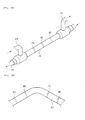
Figs. 3A and 3B are perspective views showing a double pipe type heat exchanger in accordance with the present invention. -
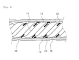
Fig. 4 is a section view showing the double pipe type heat exchanger in accordance with the present invention. -
Fig. 5 is a section view of the double pipe type heat exchanger taken along line V-V inFig. 4 . -
Fig. 6 is an enlarged section view showing major portions of the double pipe type heat exchanger in accordance with the present invention. -
Fig. 7 is a flowchart illustrating a method for manufacturing a double pipe type heat exchanger in accordance with the present invention. -
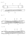
Figs. 8A through 8F are views showing the shape and arrangement of an inner pipe and an outer pipe in the respective steps of the method for manufacturing the double pipe type heat exchanger. - Certain preferred embodiments of a double pipe type heat exchanger in accordance with the present invention and a method for manufacturing the same will now be described in detail with reference to the accompanying drawings. The same reference symbols as used in describing the prior art will be used to designate the same elements.
- Referring to
Figs. 3 through 5 , the double pipe type heat exchanger in accordance with the present invention includes aninner pipe 10 and anouter pipe 20 arranged to surround theinner pipe 10. Theinner pipe 10 is provided with afirst flow path 12 defined therein. A first fluid flows along thefirst flow path 12. -
Spiral grooves 14 are formed on the outer circumferential surface of theinner pipe 10. Thespiral grooves 14 extend spirally along the outer circumferential surface of theinner pipe 10. Thespiral grooves 14 are formed by, e.g., pressing the outer circumferential surface of theinner pipe 10 with a rolling tool (not shown). - The
outer pipe 20 is arranged around theinner pipe 10 so that asecond flow path 30 can be defined between theinner pipe 10 and theouter pipe 20. In particular, thesecond flow path 30 is formed into a spiral shape due to the existence of thespiral grooves 14. - In general, the inner diameter L1 of the
outer pipe 20 is set greater than the outer diameter L2 of theinner pipe 10. This is to set to an assembling tolerance and to generate a longitudinally-extending gap G between theinner pipe 10 and theouter pipe 20. The existence of the gap G between theinner pipe 10 and theouter pipe 20 makes it possible to smoothly assemble theinner pipe 10 and theouter pipe 20 together. - A second fluid flows along the spiral
second flow path 30 defined between theinner pipe 10 and theouter pipe 20. The second fluid flowing along the spiralsecond flow path 30 differs in temperature from the first fluid flowing along thefirst flow path 12. Accordingly, a heat exchange action occurs between the first fluid and the second fluid when they flow through thefirst flow path 12 and thesecond flow path 30. - Next, the double pipe type heat exchanger of the present invention will be described in more detail with reference to
Figs. 3A, 3B and6 . - In the double pipe type heat exchanger of the present invention, the
outer pipe 20 includes one or morereduced diameter portions 40 that serve as a flow direction changing means for changing the flow direction of the second fluid flowing along thesecond flow path 30. The reduceddiameter portions 40 have a diameter L3 smaller than the diameter L4 of the remaining portions of theouter pipe 20. The reduceddiameter portions 40 are formed in the portion of theouter pipe 20 extending between aninlet pipe 24 and anoutlet pipe 26 and are arranged in a spaced-apart relationship along the longitudinal direction of theouter pipe 20. In this regard, theinlet pipe 24 is connected to one end of theouter pipe 20 so that the second fluid can be introduced into thesecond flow path 30 through theinlet pipe 24. Theoutlet pipe 26 is connected to the other end of theouter pipe 20 so that the second fluid can be discharged from thesecond flow path 30 through theoutlet pipe 26. - The reduced
diameter portions 40 of theouter pipe 20 protrude radially inwards and come into contact with the outer circumferential surface of theinner pipe 10. In particular, the reduceddiameter portions 40 are configured to make contact withspiral ridge portions 16 of theinner pipe 10 formed between thespiral grooves 14. - By making contact with the outer circumferential surface of the
inner pipe 10, the reduceddiameter portions 40 at least intermittently blocks the gap G existing between theinner pipe 10 and theouter pipe 20 with thespiral grooves 14 kept opened. Thus, the second fluid flowing straightforward along the gap G is baffled by the reduceddiameter portions 40 so that it can flow spirally along thespiral grooves 14. - As a result, it is possible to increase the time of heat exchange between the first fluid flowing along the
first flow path 12 and the second fluid flowing along thesecond flow path 30. This helps maximize the efficiency of heat exchange between the first fluid and the second fluid. - Since the reduced
diameter portions 40 remains in contact with the outer circumferential surface of theinner pipe 10, theouter pipe 20 holds theinner pipe 10 in place, thereby preventing theinner pipe 10 from moving within theouter pipe 20. This prevents occurrence of frictional contact between theinner pipe 10 and theouter pipe 20 otherwise caused by the movement of theinner pipe 10 with respect to theouter pipe 20. As a result, it is possible to prevent generation of contact noises and contact wear in theinner pipe 10 and theouter pipe 20. This assists in enhancing the durability of the heat exchanger and prolonging the lifespan thereof. - It is preferred that the reduced
diameter portions 40 be formed along the longitudinal direction of theouter pipe 20 at relatively small intervals. This is to restrain the second fluid from flowing straightforward through the gap G and to cause the second fluid to spirally flow along thespiral grooves 14. As a consequence, the second fluid spirally flowing along thesecond flow path 30 can efficiently exchange heat with the first fluid flowing through thefirst flow path 12. - The
outer pipe 20 is composed of a straight pipe portion as shown inFig. 3A . Alternatively, theouter pipe 20 may be composed of a bent pipe portion and a plurality of straight pipe portions as shown inFig. 3B . It is preferred that the reduceddiameter portions 40 be formed in the straight portion of theouter pipe 20. This is because theinner pipe 10 and theouter pipe 20 are kept in contact with each other in the bending portions thereof. - It is preferred that the reduced
diameter portions 40 be formed by a rolling work in which the outer circumferential surface of theouter pipe 20 is pressed with a forming roller to form the reduceddiameter portions 40. - If necessary, the reduced
diameter portions 40 may be formed by a press work in which the outer circumferential surface of theouter pipe 20 is pressed with a press mold to form the reduceddiameter portions 40. - Preferably, the reduced
diameter portions 40 are formed by the rolling work rather than the press work. The reason is that, if the reduceddiameter portions 40 are formed by the press work, they may be restored to the original position by the elasticity of theouter pipe 20. In the event that the reduceddiameter portions 40 are restored to the original position, they are spaced apart from the outer circumferential surface of theinner pipe 10. Thus, the reduceddiameter portions 40 fail to close the gap G existing between theinner pipe 10 and theouter pipe 20. - One example of the operation of the double pipe type heat exchanger configured as above will be described with reference to
Figs. 4 and6 . - In a state that the
inner pipe 10 is fitted into theouter pipe 20 to make contact with the reduceddiameter portions 40, the first fluid is introduced into thefirst flow path 12 of theinner pipe 10 and the second fluid is introduced into thesecond flow path 30 defined between theinner pipe 10 and theouter pipe 20. The first fluid flowing along thefirst flow path 12 makes indirect contact with the second fluid flowing along thesecond flow path 30 such that heat exchange occurs between the first fluid and the second fluid - In the areas of the
second flow path 30 where the reduceddiameter portions 40 do not exist, the second fluid flows straightforward along the gap G between theinner pipe 10 and theouter pipe 20 and also flows spirally along thespiral grooves 14 formed on theinner pipe 10. While flowing both straightforward and spirally along thesecond flow path 30, the second fluid exchanges heat with the first fluid flowing along thefirst flow path 12. - In the areas of the
second flow path 30 where the gap G is closed by the reduceddiameter portions 40, the second fluid flows spirally along thespiral grooves 14 formed on theinner pipe 10. Thus, the second fluid flowing long way along thespiral grooves 14 can efficiently exchange heat with the first fluid flowing along thefirst flow path 12. - In this manner, the second fluid repeats the straight and spiral flow and the spiral flow as it passes through the
second flow path 30. This enhances the efficiency of heat exchange between the first fluid and the second fluid, thereby significantly improving the performance of the heat exchange. - With the double pipe type heat exchanger configured as above, the gap G existing between the
inner pipe 10 and theouter pipe 20 is intermittently blocked so that the second fluid introduced into thesecond flow path 30 can spirally flow in the closed gap areas. This enables the second fluid flowing along thesecond flow path 30 to efficiently exchange heat with the first fluid flowing along thefirst flow path 12. - The efficient heat exchange between the first fluid flowing along the
first flow path 12 and the second fluid flowing along thesecond flow path 30 helps significantly enhance the performance of the heat exchanger. - Since the
outer pipe 20 has the reduceddiameter portions 40 for holding theinner pipe 10 against movement, it is possible to reliably prevent theinner pipe 10 from moving within theouter pipe 20. This makes it possible to prevent theinner pipe 10 and theouter pipe 20 from making frictional contact with each other. - By preventing the frictional contact between the
inner pipe 10 and theouter pipe 20, it is possible to prevent generation of contact noises and contact wear in theinner pipe 10 and theouter pipe 20. This makes it possible to enhance the durability of the heat exchanger and to prolong the lifespan thereof. - Next, a method for manufacturing the double pipe type heat exchanger will be described in detail with reference to
Figs. 7, 8A through8B . - As shown in
Fig. 8A , aninner pipe 10 and anouter pipe 20 are prepared first (S101 inFig. 7 ). Then, as shown inFig. 8B ,spiral grooves 14 are formed on the outer circumferential surface of theinner pipe 10 andenlarged pipe portions 22 are formed in the opposite end portions of the outer pipe 20 (S103 inFig. 7 ). Thespiral grooves 14 are formed by, e.g., a rolling work in which the outer circumferential surface of theinner pipe 10 is pressed with a forming roller. Theenlarged pipe portions 22 are formed by, e.g., a pipe-enlarging press work in which opposite end portions of theouter pipe 20 are enlarged with a press machine. - Upon finishing formation of the
spiral grooves 14 and theenlarged pipe portions 22, theinner pipe 10 is inserted into theouter pipe 20 as shown inFig. 8C (S105 inFig. 7 ). Subsequently, theinner pipe 10 and theouter pipe 20 are welded together at their opposite ends as shown inFig. 8C (S107 inFig. 7 ) . - Thereafter, the
inner pipe 10 and theouter pipe 20 are bent into a desired shape as shown inFig. 8E (S108 inFig. 7 ). As a result, theinner pipe 10 and theouter pipe 20 come into contact with each other in the bent portions thereof. - Then, as shown in
Fig. 8F , a plurality of reduceddiameter portions 40 is formed in theouter pipe 20 at a desired interval (S109 inFig. 7 ) by deforming theouter pipe 20. The reduceddiameter portions 40 is formed by, e.g., a rolling work in which the outer circumferential surface of theouter pipe 20 is pressed with a forming roller. If necessary, aninlet pipe 24 and anoutlet pipe 26 for introducing and discharging a second fluid therethrough are fitted to theenlarged pipe portions 22 of theouter pipe 20. - The double pipe type heat exchanger manufactured through the afore-mentioned steps has a
first flow path 12 through which a first fluid can flow, asecond flow path 30 through which a second fluid can flow and a plurality of reduceddiameter portions 40 arranged along theouter pipe 20 at a specified interval. - The reduced
diameter portions 40 of theouter pipe 20 protrude radially inwards to make contact with the outer circumferential surface of theinner pipe 10. Thus, the gap G existing between theinner pipe 10 and theouter pipe 20 is at least intermittently blocked by the reduceddiameter portions 40. Theinner pipe 10 is held against movement by the reduceddiameter portions 40 of theouter pipe 20. - While certain preferred embodiments of the invention have been described hereinabove, the present invention is not limited to these embodiments. It is to be understood that various changes and modifications may be made without departing from the scope of the invention defined in the claims.
Claims (13)
- A double pipe type heat exchanger, comprising:an inner pipe (10) having a first flow path (12) defined therein; andan outer pipe (20) arranged around the inner pipe (10) to define a second flow path (30) between the inner pipe (10) and the outer pipe (20), characterized in that:the inner pipe (10) includes a spiral groove (14) formed on an outer circumferential surface of the inner pipe (10) to extend along a longitudinal direction of the inner pipe (10), the outer pipe (20) including a reduced diameter portion (40) protruding inwardly so that the inner surface of the outer pipe (20) is intermittently contacted with the outer circumferential surface of the inner pipe (10).
- The heat exchanger as recited in claim 1, characterized in that a longitudinally-extending gap (G) exists between the inner pipe (10) and the outer pipe (20), the gap (G) being at least intermittently blocked by the reduced diameter portion (40) along the longitudinal direction of the inner and outer pipe (10, 20) to allow a fluid to flow through the spiral groove (14) only.
- The heat exchanger as recited in claim 2, characterized in that the inner pipe (10) includes a spiral ridge portion (16) formed on the outer circumferential surface of the inner pipe (10) to define the spiral groove (14), the reduced diameter portion (40) being kept in contact with the spiral ridge portion (16).
- The heat exchanger as recited in claim 1, characterized in that the outer pipe (20) includes a straight pipe portion and a bent pipe portion, the reduced diameter portion (40) being formed in the straight pipe portion.
- The heat exchanger as recited in claim 1, characterized by further comprising:an inlet pipe (24) connected to one end of the outer pipe (20) for introduction of a fluid into the second flow path (30) therethrough; andan outlet pipe (26) connected to the other end of the outer pipe (20) for discharge of the fluid from the second flow path (30) therethrough, the reduced diameter portion being (40) formed on the outer pipe (20) between the inlet pipe (24) and the outlet pipe (26); preferably characterized in that the outer pipe (20) includes a straight pipe portion and a bent pipe portion arranged between the inlet pipe (24) and the outlet pipe (26), the reduced diameter portion (40) being formed in the straight pipe portion.
- The heat exchanger as recited in claim 2, characterized in that the second flow path (30) is defined by the spiral groove (14) for allowing a fluid to flow spirally therethrough and the gap (G) for allowing the fluid to flow straightforward therethrough, the reduced diameter portion (40) being configured to at least intermittently block the gap (G) such that the second fluid flows spirally through the spiral groove (14) only.
- The heat exchanger as recited in any one of claims 1 to 6, characterized in that the reduced diameter portion (40) includes a plurality of reduced diameter portions (40) arranged along a longitudinal direction of the outer pipe (20) at a predetermined interval; or is characterized in that the reduced diameter portion (40) is configured to extend in a circumferential direction of the outer pipe (20) and is formed by reducing a diameter of the outer pipe (20).
- A double pipe type heat exchanger, comprising:an inner pipe (10) having a first flow path (12) defined therein; andan outer pipe (20) arranged around the inner pipe (10) to define a second flow path (30) between the inner pipe (10) and the outer pipe (20), characterized in that:the second flow path (30) includes a longitudinally-extending gap (G) existing between the inner pipe (10) and the outer pipe (20) and a spiral groove (14) formed on an outer circumferential surface of the inner pipe (10), the outer pipe (20) including a flow direction changing member for changing a flow direction of a fluid flowing along the second flow path (30).
- The heat exchanger as recited in claim 8, characterized in that the flow direction changing member includes a plurality of reduced diameter portions (40) formed by pressing the outer pipe (20) intermittently toward the circumferential surface of the inner pipe (10); preferably characterized in that the flow direction changing member is configured to at least intermittently block the gap (G) for changing the second flow direction from the straightforward and spiral flow to spiral flow only.
- A method for manufacturing a double pipe type heat exchanger including an inner pipe (10) having a first flow path (12) defined therein and an outer pipe (20) arranged around the inner pipe (10) to define a second flow path between the inner pipe (10) and the outer pipe (20), characterized by comprising the steps of:a) forming a spiral groove (14) on an outer circumferential surface of the inner pipe (10) and forming a pair of enlarged pipe portions in opposite end portions of the outer pipe (20);b) inserting the inner pipe (10) into the outer pipe (20) ;c) fixing both ends of the inner pipe (10) and the outer pipe (20) together; andd) deforming the outer pipe (20) to form a reduced diameter portion (40) protruding toward the outer circumferential surface of the inner pipe (10).
- The method as recited in claim 10 characterized in that, in step d), the reduced diameter portion (40) is formed to make contact with the outer circumferential surface of the inner pipe (10).
- The method as recited in claim 10, characterized by further comprising, after step c) and before step d), the step of:bending the outer pipe (20) together with the inner pipe (10) such that a straight pipe portion and a bent pipe portion are formed in the outer pipe (20).
- The method as recited in claim 12, characterized in that, in step d), the reduced diameter portion (40) is formed in multiple numbers along the straight pipe portion of the outer pipe (20).
Applications Claiming Priority (1)
| Application Number | Priority Date | Filing Date | Title |
|---|---|---|---|
| KR1020100079940A KR101600296B1 (en) | 2010-08-18 | 2010-08-18 | Double pipe heat exchanger and manufacturing method the same |
Publications (3)
| Publication Number | Publication Date |
|---|---|
| EP2420790A2 true EP2420790A2 (en) | 2012-02-22 |
| EP2420790A3 EP2420790A3 (en) | 2013-11-13 |
| EP2420790B1 EP2420790B1 (en) | 2018-05-23 |
Family
ID=44118122
Family Applications (1)
| Application Number | Title | Priority Date | Filing Date |
|---|---|---|---|
| EP11168401.5A Active EP2420790B1 (en) | 2010-08-18 | 2011-06-01 | Double pipe type heat exchanger and method for manufacturing the same |
Country Status (4)
| Country | Link |
|---|---|
| US (2) | US9091487B2 (en) |
| EP (1) | EP2420790B1 (en) |
| KR (1) | KR101600296B1 (en) |
| CN (2) | CN102374802A (en) |
Cited By (9)
| Publication number | Priority date | Publication date | Assignee | Title |
|---|---|---|---|---|
| US20140202167A1 (en) * | 2013-01-18 | 2014-07-24 | Mitsubishi Heavy Industries, Ltd. | Power generation system |
| US20150114611A1 (en) * | 2013-10-28 | 2015-04-30 | Honeywell International Inc. | Counter-flow heat exchange systems |
| WO2015121327A1 (en) * | 2014-02-12 | 2015-08-20 | Eaton Industrial IP GmbH & Co. KG | Heat exchanger |
| WO2016012664A1 (en) * | 2014-07-25 | 2016-01-28 | Hutchinson | Heat exchanger such as an internal exchanger for a motor vehicle air-conditioning system and system including same |
| US9752835B2 (en) | 2013-06-06 | 2017-09-05 | Honeywell International Inc. | Unitary heat exchangers having integrally-formed compliant heat exchanger tubes and heat exchange systems including the same |
| EP3306248A1 (en) * | 2016-10-05 | 2018-04-11 | Hs R & A Co., Ltd. | Double pipe heat exchanger and method for manufacturing the same |
| JP2020012619A (en) * | 2018-07-20 | 2020-01-23 | 株式会社ヴァレオジャパン | Double-pipe heat exchanger |
| EP3679312A4 (en) * | 2017-09-06 | 2021-03-31 | Contitech Fluid Korea Ltd. | Double tube for heat exchange |
| EP4119880A1 (en) * | 2021-07-13 | 2023-01-18 | Hung-Sen Chang | Eddy fluid heat exchange device |
Families Citing this family (43)
| Publication number | Priority date | Publication date | Assignee | Title |
|---|---|---|---|---|
| DE102009057232A1 (en) * | 2009-12-05 | 2011-06-09 | GM Global Technology Operations LLC, ( n. d. Ges. d. Staates Delaware ), Detroit | Tubular heat exchanger for automotive air conditioning |
| KR101600296B1 (en) | 2010-08-18 | 2016-03-07 | 한온시스템 주식회사 | Double pipe heat exchanger and manufacturing method the same |
| DE102013100886B4 (en) * | 2013-01-29 | 2015-01-08 | Benteler Automobiltechnik Gmbh | Heat exchanger for a motor vehicle with a double-walled heat exchanger tube |
| US20140112650A1 (en) * | 2012-10-19 | 2014-04-24 | Edwards Vacuum, Inc. | Cartridge heater apparatus |
| WO2014131093A2 (en) * | 2013-03-01 | 2014-09-04 | Acv International | Facility for producing a hot liquid, in particular hot water |
| US9644898B2 (en) * | 2013-07-09 | 2017-05-09 | The Boeing Company | Systems and methods for heat balance and transport for aircraft hydraulic systems |
| US9644648B2 (en) * | 2013-07-09 | 2017-05-09 | The Boeing Company | Systems and methods for heat balance and transport for aircraft hydraulic systems |
| US9539631B2 (en) * | 2013-09-13 | 2017-01-10 | Hanon Systems | Manufacturing process for tube-in-tube internal heat exchanger |
| CN105258400B (en) * | 2014-07-18 | 2018-01-02 | 上海交通大学 | Coaxial threaded pipe leaks flow heat exchanger |
| CN104896563A (en) * | 2015-06-03 | 2015-09-09 | 宁波格林美孚新材料科技有限公司 | Electromagnetic heating and warming device |
| GB201513415D0 (en) * | 2015-07-30 | 2015-09-16 | Senior Uk Ltd | Finned coaxial cooler |
| CN106482568B (en) * | 2015-08-25 | 2019-03-12 | 丹佛斯微通道换热器(嘉兴)有限公司 | Heat exchange tube for heat exchanger, heat exchanger and assembling method thereof |
| JP2016053469A (en) * | 2015-09-04 | 2016-04-14 | 株式会社ヴァレオジャパン | Manufacturing method of double pipe |
| CN105299959A (en) * | 2015-11-10 | 2016-02-03 | 苏州海而仕信息科技有限公司 | Pipe type heat exchanger |
| CN105276867A (en) * | 2015-11-10 | 2016-01-27 | 苏州海而仕信息科技有限公司 | Pipeline type heat exchanger |
| CN108778547B (en) * | 2015-12-18 | 2021-02-09 | 山特维克原料技术德国公开股份有限公司 | Method for producing a tube made of metal and a tube made of metal |
| JP2016095132A (en) * | 2016-02-26 | 2016-05-26 | 株式会社ヴァレオジャパン | Method for manufacturing double pipe |
| WO2017159542A1 (en) * | 2016-03-14 | 2017-09-21 | カルソニックカンセイ株式会社 | Double pipe |
| JP2017198392A (en) * | 2016-04-27 | 2017-11-02 | 株式会社ヴァレオジャパン | Double tube |
| EP3458789B1 (en) * | 2016-05-20 | 2022-02-16 | ContiTech Fluid Korea Co., Ltd. | Double tube for heat-exchange |
| KR101759110B1 (en) * | 2016-08-10 | 2017-07-19 | 주식회사 화승알앤에이 | Double pipe heat exchanger and method for manufacturing the same |
| CN106216553B (en) * | 2016-08-22 | 2018-04-27 | 常州市盛士达汽车空调有限公司 | Air conditioning for automobiles heat exchange pipe preparation method |
| CN106369272B (en) * | 2016-08-26 | 2018-12-28 | 江苏中圣压力容器装备制造有限公司 | Liquefied natural gas (LNG) gasifier efficient heat-exchanging pipe and open-frame type gasifier |
| US20180100705A1 (en) * | 2016-10-11 | 2018-04-12 | Penn Aluminum International LLC | Extruded Tube For Simplifying The Formation Of An Internal Heat Exchanger For A Closed Cycle Refrigeration System |
| CN108154941B (en) * | 2016-12-05 | 2024-08-06 | 国家电投集团科学技术研究院有限公司 | External air cooler for reactor containment |
| US10794203B2 (en) * | 2017-03-22 | 2020-10-06 | General Electric Company | Scavenge tube for a gas turbine engine |
| CN108362157A (en) * | 2017-11-19 | 2018-08-03 | 江阴伊克赛特汽车饰件有限公司 | A kind of automobile intersection internal thread tubular type moulding |
| US10808874B2 (en) * | 2017-11-30 | 2020-10-20 | General Electric Company | Inline fluid damper device |
| JP2019132509A (en) * | 2018-01-31 | 2019-08-08 | 株式会社デンソー | Double-pipe heat exchanger |
| CN108870989A (en) * | 2018-05-16 | 2018-11-23 | 盐城项远环保设备有限公司 | A kind of residual neat recovering system |
| JP7233857B2 (en) * | 2018-06-12 | 2023-03-07 | 株式会社Uacj | Double tube joining method in heat exchanger |
| KR102552158B1 (en) * | 2018-07-27 | 2023-07-05 | 현대자동차주식회사 | Double pipe heat exchanger and manufacturing method of the same |
| KR20200045727A (en) * | 2018-10-23 | 2020-05-06 | 현대자동차주식회사 | Heat pump system for vehicle |
| CN109520354B (en) * | 2018-12-17 | 2021-11-30 | 青岛钛钽铌锆连续化反应器有限公司 | Reaction/mixing/heat exchange tube and reactor |
| JP7474577B2 (en) * | 2019-10-23 | 2024-04-25 | 株式会社Uacj | Heat transfer double tube, inner tube for heat transfer double tube and manufacturing method thereof |
| JP6823906B1 (en) * | 2019-12-13 | 2021-02-03 | 株式会社Uacj | Double tube for heat exchanger |
| WO2021241422A1 (en) * | 2020-05-27 | 2021-12-02 | 株式会社デンソーエアシステムズ | Internal heat exchanger, and method for producing internal heat exchanger |
| KR102438785B1 (en) * | 2021-02-09 | 2022-09-01 | 이성민 | Manufacturing method of tube for heat exchanger, tube for heat exchanger manufactured thereby, and heat exchanger |
| CN113108642B (en) * | 2021-04-13 | 2022-11-18 | 山东鑫华星暖通科技有限公司 | Bimetal composite radiator capable of reducing friction abnormal sound and preparation method thereof |
| CN115420122B (en) * | 2022-11-03 | 2023-02-28 | 涉县津东经贸有限责任公司 | A temperature-controllable casing heat exchanger |
| CN117824214A (en) * | 2023-12-28 | 2024-04-05 | 福建宏泰智能工业互联网有限公司 | Direct cooling pipe and water refrigerating device of air water making machine |
| CN118398580A (en) * | 2024-04-22 | 2024-07-26 | 全骏(上海)贸易有限公司 | Concentric tube heat-carrying device |
| CN119915028B (en) * | 2025-04-02 | 2025-06-03 | 大连冰森林制冷技术有限公司 | A carbon dioxide regenerator |
Family Cites Families (43)
| Publication number | Priority date | Publication date | Assignee | Title |
|---|---|---|---|---|
| US2157252A (en) * | 1937-03-31 | 1939-05-09 | Oldberg Mfg Co | Rolling-in machine |
| US2259433A (en) * | 1937-11-15 | 1941-10-14 | Hoover Co | Heat exchanger |
| US2864588A (en) * | 1955-03-25 | 1958-12-16 | United Aircraft Prod | Heat transfer method |
| US3104735A (en) * | 1960-11-14 | 1963-09-24 | Arvin Ind Inc | Sound attenuating gas pipe |
| US3259206A (en) * | 1964-06-18 | 1966-07-05 | Walker Mfg Co | Exhaust pipe silencer with side branch chambers and baffled elbow sections |
| US3566615A (en) * | 1969-04-03 | 1971-03-02 | Whirlpool Co | Heat exchanger with rolled-in capillary for refrigeration apparatus |
| US3730229A (en) * | 1971-03-11 | 1973-05-01 | Turbotec Inc | Tubing unit with helically corrugated tube and method for making same |
| SE374192B (en) * | 1973-02-13 | 1975-02-24 | Sarlab Ag | |
| DE2320125C3 (en) * | 1973-04-19 | 1980-03-06 | Spiral Tubing Corp., New Britain, Conn. (V.St.A.) | Method of manufacturing a pipe unit |
| US3916504A (en) * | 1973-10-02 | 1975-11-04 | Universal Oil Prod Co | Method of making spiral tube mixing device |
| US4194560A (en) * | 1976-03-19 | 1980-03-25 | Nihon Radiator Co., Ltd. | Oil cooler and method for forming it |
| US4086959A (en) * | 1976-07-19 | 1978-05-02 | Uop Inc. | Automotive oil cooler |
| US4372374A (en) * | 1980-01-15 | 1983-02-08 | Ateliers Des Charmilles S.A. | Vented heat transfer tube assembly |
| JPS5737690A (en) * | 1980-08-15 | 1982-03-02 | Hitachi Ltd | Heat exchanger |
| US4559999A (en) * | 1983-04-08 | 1985-12-24 | Shiley, Inc. | Heat exchanger for extracorporeal circuit |
| JPS6038371U (en) * | 1983-08-19 | 1985-03-16 | 深澤 一仁 | heat exchange pipe |
| US4878537A (en) * | 1986-05-27 | 1989-11-07 | Level 1 Technologies | Heat exchanger for physiological fluids |
| US5375654A (en) * | 1993-11-16 | 1994-12-27 | Fr Mfg. Corporation | Turbulating heat exchange tube and system |
| DE19548341C1 (en) * | 1995-12-22 | 1996-12-19 | Daimler Benz Ag | Rigid connection for overlapping motor vehicle body parts |
| JPH1038491A (en) * | 1996-07-23 | 1998-02-13 | Toyo Radiator Co Ltd | Double tube heat exchanger |
| DE19909368C1 (en) * | 1999-03-03 | 2000-08-10 | Hde Metallwerk Gmbh | Heat exchanger tube with inner and outer tubes involves at least one tube with rib type formations forming screw-line flow channel over axial length |
| US20010045275A1 (en) * | 2000-05-25 | 2001-11-29 | Hoshizaki Denki Kabushiki Kaisha | Cylindrical heat exchanger |
| JP2002318015A (en) * | 2001-04-17 | 2002-10-31 | Orion Mach Co Ltd | Refrigeration equipment |
| US20040007350A1 (en) * | 2002-07-15 | 2004-01-15 | Lambert Wu | Energy exchanging apparatus |
| JP3811123B2 (en) * | 2002-12-10 | 2006-08-16 | 松下電器産業株式会社 | Double tube heat exchanger |
| JP2004270916A (en) * | 2003-02-17 | 2004-09-30 | Calsonic Kansei Corp | Double tube and method for producing the same |
| JP2004278854A (en) * | 2003-03-13 | 2004-10-07 | Toyo Radiator Co Ltd | Double-walled pipe heat exchanger and its manufacturing method |
| US7920779B2 (en) * | 2003-12-10 | 2011-04-05 | Panasonic Corporation | Heat exchanger and washing apparatus comprising the same |
| US7011150B2 (en) * | 2004-04-20 | 2006-03-14 | Tokyo Radiator Mfg. Co., Ltd. | Tube structure of multitubular heat exchanger |
| CN100460794C (en) * | 2004-11-09 | 2009-02-11 | 株式会社电装 | Double-walled tube, manufacturing method thereof, and refrigerant cycle device provided with double-walled tube |
| JP2006132905A (en) * | 2004-11-09 | 2006-05-25 | Denso Corp | Refrigeration cycle |
| DE102005052973B4 (en) * | 2004-11-09 | 2014-11-20 | Denso Corporation | Double-walled pipe and manufacturing method therefor |
| JP4698417B2 (en) * | 2005-12-28 | 2011-06-08 | 株式会社デンソー | Manufacturing method of double pipe |
| JP2007218486A (en) * | 2006-02-15 | 2007-08-30 | Hitachi Cable Ltd | Heat exchanger tube for heat exchanger and heat exchanger using the same |
| JP2008232449A (en) * | 2007-03-16 | 2008-10-02 | Sumitomo Light Metal Ind Ltd | Double tube heat exchanger and method for manufacturing the same |
| JP2009041798A (en) * | 2007-08-07 | 2009-02-26 | Showa Denko Kk | Heat exchanger |
| JP5202030B2 (en) * | 2008-02-26 | 2013-06-05 | 株式会社ケーヒン・サーマル・テクノロジー | Double tube heat exchanger |
| GB0909221D0 (en) * | 2009-04-30 | 2009-07-15 | Eaton Fluid Power Gmbh | Heat exchanger |
| JP5504050B2 (en) * | 2009-06-30 | 2014-05-28 | 株式会社ケーヒン・サーマル・テクノロジー | Double tube heat exchanger and method for manufacturing the same |
| KR101608996B1 (en) * | 2010-01-11 | 2016-04-05 | 엘지전자 주식회사 | Heat exchanger |
| KR101600296B1 (en) | 2010-08-18 | 2016-03-07 | 한온시스템 주식회사 | Double pipe heat exchanger and manufacturing method the same |
| KR200459178Y1 (en) * | 2011-07-26 | 2012-03-22 | 최건식 | Double tube type heat exchange pipe |
| JP6172950B2 (en) * | 2012-02-01 | 2017-08-02 | 株式会社Uacj | Double tube for heat exchanger |
-
2010
- 2010-08-18 KR KR1020100079940A patent/KR101600296B1/en active Active
-
2011
- 2011-06-01 EP EP11168401.5A patent/EP2420790B1/en active Active
- 2011-06-02 US US13/152,184 patent/US9091487B2/en active Active
- 2011-06-30 CN CN201110181422XA patent/CN102374802A/en active Pending
- 2011-06-30 CN CN201611019713.8A patent/CN106895716A/en active Pending
-
2015
- 2015-04-27 US US14/696,491 patent/US9821364B2/en active Active
Non-Patent Citations (1)
| Title |
|---|
| None |
Cited By (13)
| Publication number | Priority date | Publication date | Assignee | Title |
|---|---|---|---|---|
| US20140202167A1 (en) * | 2013-01-18 | 2014-07-24 | Mitsubishi Heavy Industries, Ltd. | Power generation system |
| US9752835B2 (en) | 2013-06-06 | 2017-09-05 | Honeywell International Inc. | Unitary heat exchangers having integrally-formed compliant heat exchanger tubes and heat exchange systems including the same |
| US20150114611A1 (en) * | 2013-10-28 | 2015-04-30 | Honeywell International Inc. | Counter-flow heat exchange systems |
| US9764435B2 (en) * | 2013-10-28 | 2017-09-19 | Honeywell International Inc. | Counter-flow heat exchange systems |
| WO2015121327A1 (en) * | 2014-02-12 | 2015-08-20 | Eaton Industrial IP GmbH & Co. KG | Heat exchanger |
| WO2016012664A1 (en) * | 2014-07-25 | 2016-01-28 | Hutchinson | Heat exchanger such as an internal exchanger for a motor vehicle air-conditioning system and system including same |
| EP3306248A1 (en) * | 2016-10-05 | 2018-04-11 | Hs R & A Co., Ltd. | Double pipe heat exchanger and method for manufacturing the same |
| US11067340B2 (en) | 2016-10-05 | 2021-07-20 | HS R & A Co., Ltd | Double pipe heat exchanger and method for manufacturing the same |
| EP3679312A4 (en) * | 2017-09-06 | 2021-03-31 | Contitech Fluid Korea Ltd. | Double tube for heat exchange |
| JP2020012619A (en) * | 2018-07-20 | 2020-01-23 | 株式会社ヴァレオジャパン | Double-pipe heat exchanger |
| EP3614074A1 (en) * | 2018-07-20 | 2020-02-26 | Valeo Japan Co., Ltd. | Double-pipe eat exchanger |
| EP4119880A1 (en) * | 2021-07-13 | 2023-01-18 | Hung-Sen Chang | Eddy fluid heat exchange device |
| US11698227B2 (en) | 2021-07-13 | 2023-07-11 | Hung-Sen Chang | Eddy fluid heat exchange device |
Also Published As
| Publication number | Publication date |
|---|---|
| KR101600296B1 (en) | 2016-03-07 |
| EP2420790A3 (en) | 2013-11-13 |
| CN102374802A (en) | 2012-03-14 |
| US9821364B2 (en) | 2017-11-21 |
| KR20120017315A (en) | 2012-02-28 |
| US20150224561A1 (en) | 2015-08-13 |
| US9091487B2 (en) | 2015-07-28 |
| EP2420790B1 (en) | 2018-05-23 |
| CN106895716A (en) | 2017-06-27 |
| US20120043055A1 (en) | 2012-02-23 |
Similar Documents
| Publication | Publication Date | Title |
|---|---|---|
| US9821364B2 (en) | Double pipe type heat exchanger and method for manufacturing the same | |
| US10113811B2 (en) | Tube for heat exchanger | |
| JP2007139416A (en) | Metal plate for producing flat tube, flat tube, and its manufacturing method | |
| KR20150053135A (en) | Heat exchanger and Manufacturing method fo the same | |
| CN114761750B (en) | Double tube for heat exchanger | |
| US20100051252A1 (en) | Heat exchanger | |
| US20070266730A1 (en) | Refrigerant Distributor and Method for Manufacturing the Same | |
| EP4317892A1 (en) | Heat exchanger with heat transfer augmentation features | |
| EP4317891A1 (en) | Heat exchanger with heat transfer augmentation features | |
| JP2016097434A (en) | Tube for heat exchanger and its manufacturing method | |
| KR102552158B1 (en) | Double pipe heat exchanger and manufacturing method of the same | |
| JP4722577B2 (en) | Oil cooler | |
| KR20120090218A (en) | Double pipe heat exchanger | |
| JP2007093036A (en) | Heat exchanger, method for manufacturing the same, and apparatus for manufacturing the same | |
| KR20130001544A (en) | Method of manufacturing the double-wall pipe and double-wall pipe thereof | |
| JP5167930B2 (en) | Heat exchanger | |
| JP5107641B2 (en) | Manufacturing method of heat exchanger | |
| JP6471353B2 (en) | Heat exchanger and heat pump water heater using the same | |
| KR101128415B1 (en) | Baffles for heat exchangers | |
| CN114599463A (en) | Manufacturing method of double tubular heat exchanger | |
| JPH031097A (en) | Heat exchanger | |
| JP5066708B2 (en) | Plate for flat tube manufacturing | |
| KR20000031980A (en) | Structure of bullet for expansion of tube of fin tube type heat exchanger | |
| JP2007292403A (en) | Tube and tube manufacturing method | |
| JP3886512B2 (en) | Spiral fin tube |
Legal Events
| Date | Code | Title | Description |
|---|---|---|---|
| AK | Designated contracting states |
Kind code of ref document: A2 Designated state(s): AL AT BE BG CH CY CZ DE DK EE ES FI FR GB GR HR HU IE IS IT LI LT LU LV MC MK MT NL NO PL PT RO RS SE SI SK SM TR |
|
| AX | Request for extension of the european patent |
Extension state: BA ME |
|
| PUAI | Public reference made under article 153(3) epc to a published international application that has entered the european phase |
Free format text: ORIGINAL CODE: 0009012 |
|
| PUAL | Search report despatched |
Free format text: ORIGINAL CODE: 0009013 |
|
| RAP1 | Party data changed (applicant data changed or rights of an application transferred) |
Owner name: HALLA VISTEON CLIMATE CONTROL CORP. |
|
| AK | Designated contracting states |
Kind code of ref document: A3 Designated state(s): AL AT BE BG CH CY CZ DE DK EE ES FI FR GB GR HR HU IE IS IT LI LT LU LV MC MK MT NL NO PL PT RO RS SE SI SK SM TR |
|
| AX | Request for extension of the european patent |
Extension state: BA ME |
|
| RIC1 | Information provided on ipc code assigned before grant |
Ipc: F28D 7/10 20060101AFI20131004BHEP Ipc: F28F 1/42 20060101ALI20131004BHEP Ipc: F28D 7/14 20060101ALI20131004BHEP |
|
| 17P | Request for examination filed |
Effective date: 20140513 |
|
| RBV | Designated contracting states (corrected) |
Designated state(s): AL AT BE BG CH CY CZ DE DK EE ES FI FR GB GR HR HU IE IS IT LI LT LU LV MC MK MT NL NO PL PT RO RS SE SI SK SM TR |
|
| 17Q | First examination report despatched |
Effective date: 20151210 |
|
| RAP1 | Party data changed (applicant data changed or rights of an application transferred) |
Owner name: HANON SYSTEMS |
|
| GRAP | Despatch of communication of intention to grant a patent |
Free format text: ORIGINAL CODE: EPIDOSNIGR1 |
|
| RIC1 | Information provided on ipc code assigned before grant |
Ipc: B21D 53/06 20060101ALI20171205BHEP Ipc: F28D 7/14 20060101ALI20171205BHEP Ipc: F28F 1/42 20060101ALI20171205BHEP Ipc: F28D 7/10 20060101AFI20171205BHEP |
|
| INTG | Intention to grant announced |
Effective date: 20180102 |
|
| GRAS | Grant fee paid |
Free format text: ORIGINAL CODE: EPIDOSNIGR3 |
|
| GRAA | (expected) grant |
Free format text: ORIGINAL CODE: 0009210 |
|
| AK | Designated contracting states |
Kind code of ref document: B1 Designated state(s): AL AT BE BG CH CY CZ DE DK EE ES FI FR GB GR HR HU IE IS IT LI LT LU LV MC MK MT NL NO PL PT RO RS SE SI SK SM TR |
|
| REG | Reference to a national code |
Ref country code: GB Ref legal event code: FG4D |
|
| REG | Reference to a national code |
Ref country code: CH Ref legal event code: EP |
|
| REG | Reference to a national code |
Ref country code: IE Ref legal event code: FG4D |
|
| REG | Reference to a national code |
Ref country code: DE Ref legal event code: R096 Ref document number: 602011048526 Country of ref document: DE |
|
| REG | Reference to a national code |
Ref country code: AT Ref legal event code: REF Ref document number: 1001846 Country of ref document: AT Kind code of ref document: T Effective date: 20180615 |
|
| REG | Reference to a national code |
Ref country code: FR Ref legal event code: PLFP Year of fee payment: 8 |
|
| REG | Reference to a national code |
Ref country code: NL Ref legal event code: MP Effective date: 20180523 |
|
| REG | Reference to a national code |
Ref country code: LT Ref legal event code: MG4D |
|
| PG25 | Lapsed in a contracting state [announced via postgrant information from national office to epo] |
Ref country code: ES Free format text: LAPSE BECAUSE OF FAILURE TO SUBMIT A TRANSLATION OF THE DESCRIPTION OR TO PAY THE FEE WITHIN THE PRESCRIBED TIME-LIMIT Effective date: 20180523 Ref country code: SE Free format text: LAPSE BECAUSE OF FAILURE TO SUBMIT A TRANSLATION OF THE DESCRIPTION OR TO PAY THE FEE WITHIN THE PRESCRIBED TIME-LIMIT Effective date: 20180523 Ref country code: FI Free format text: LAPSE BECAUSE OF FAILURE TO SUBMIT A TRANSLATION OF THE DESCRIPTION OR TO PAY THE FEE WITHIN THE PRESCRIBED TIME-LIMIT Effective date: 20180523 Ref country code: BG Free format text: LAPSE BECAUSE OF FAILURE TO SUBMIT A TRANSLATION OF THE DESCRIPTION OR TO PAY THE FEE WITHIN THE PRESCRIBED TIME-LIMIT Effective date: 20180823 Ref country code: NO Free format text: LAPSE BECAUSE OF FAILURE TO SUBMIT A TRANSLATION OF THE DESCRIPTION OR TO PAY THE FEE WITHIN THE PRESCRIBED TIME-LIMIT Effective date: 20180823 Ref country code: LT Free format text: LAPSE BECAUSE OF FAILURE TO SUBMIT A TRANSLATION OF THE DESCRIPTION OR TO PAY THE FEE WITHIN THE PRESCRIBED TIME-LIMIT Effective date: 20180523 |
|
| PG25 | Lapsed in a contracting state [announced via postgrant information from national office to epo] |
Ref country code: GR Free format text: LAPSE BECAUSE OF FAILURE TO SUBMIT A TRANSLATION OF THE DESCRIPTION OR TO PAY THE FEE WITHIN THE PRESCRIBED TIME-LIMIT Effective date: 20180824 Ref country code: HR Free format text: LAPSE BECAUSE OF FAILURE TO SUBMIT A TRANSLATION OF THE DESCRIPTION OR TO PAY THE FEE WITHIN THE PRESCRIBED TIME-LIMIT Effective date: 20180523 Ref country code: NL Free format text: LAPSE BECAUSE OF FAILURE TO SUBMIT A TRANSLATION OF THE DESCRIPTION OR TO PAY THE FEE WITHIN THE PRESCRIBED TIME-LIMIT Effective date: 20180523 Ref country code: LV Free format text: LAPSE BECAUSE OF FAILURE TO SUBMIT A TRANSLATION OF THE DESCRIPTION OR TO PAY THE FEE WITHIN THE PRESCRIBED TIME-LIMIT Effective date: 20180523 Ref country code: RS Free format text: LAPSE BECAUSE OF FAILURE TO SUBMIT A TRANSLATION OF THE DESCRIPTION OR TO PAY THE FEE WITHIN THE PRESCRIBED TIME-LIMIT Effective date: 20180523 |
|
| REG | Reference to a national code |
Ref country code: AT Ref legal event code: MK05 Ref document number: 1001846 Country of ref document: AT Kind code of ref document: T Effective date: 20180523 |
|
| PG25 | Lapsed in a contracting state [announced via postgrant information from national office to epo] |
Ref country code: CZ Free format text: LAPSE BECAUSE OF FAILURE TO SUBMIT A TRANSLATION OF THE DESCRIPTION OR TO PAY THE FEE WITHIN THE PRESCRIBED TIME-LIMIT Effective date: 20180523 Ref country code: RO Free format text: LAPSE BECAUSE OF FAILURE TO SUBMIT A TRANSLATION OF THE DESCRIPTION OR TO PAY THE FEE WITHIN THE PRESCRIBED TIME-LIMIT Effective date: 20180523 Ref country code: EE Free format text: LAPSE BECAUSE OF FAILURE TO SUBMIT A TRANSLATION OF THE DESCRIPTION OR TO PAY THE FEE WITHIN THE PRESCRIBED TIME-LIMIT Effective date: 20180523 Ref country code: AT Free format text: LAPSE BECAUSE OF FAILURE TO SUBMIT A TRANSLATION OF THE DESCRIPTION OR TO PAY THE FEE WITHIN THE PRESCRIBED TIME-LIMIT Effective date: 20180523 Ref country code: DK Free format text: LAPSE BECAUSE OF FAILURE TO SUBMIT A TRANSLATION OF THE DESCRIPTION OR TO PAY THE FEE WITHIN THE PRESCRIBED TIME-LIMIT Effective date: 20180523 Ref country code: PL Free format text: LAPSE BECAUSE OF FAILURE TO SUBMIT A TRANSLATION OF THE DESCRIPTION OR TO PAY THE FEE WITHIN THE PRESCRIBED TIME-LIMIT Effective date: 20180523 Ref country code: SK Free format text: LAPSE BECAUSE OF FAILURE TO SUBMIT A TRANSLATION OF THE DESCRIPTION OR TO PAY THE FEE WITHIN THE PRESCRIBED TIME-LIMIT Effective date: 20180523 |
|
| REG | Reference to a national code |
Ref country code: CH Ref legal event code: PL |
|
| REG | Reference to a national code |
Ref country code: DE Ref legal event code: R097 Ref document number: 602011048526 Country of ref document: DE |
|
| PG25 | Lapsed in a contracting state [announced via postgrant information from national office to epo] |
Ref country code: SM Free format text: LAPSE BECAUSE OF FAILURE TO SUBMIT A TRANSLATION OF THE DESCRIPTION OR TO PAY THE FEE WITHIN THE PRESCRIBED TIME-LIMIT Effective date: 20180523 Ref country code: IT Free format text: LAPSE BECAUSE OF FAILURE TO SUBMIT A TRANSLATION OF THE DESCRIPTION OR TO PAY THE FEE WITHIN THE PRESCRIBED TIME-LIMIT Effective date: 20180523 |
|
| REG | Reference to a national code |
Ref country code: BE Ref legal event code: MM Effective date: 20180630 |
|
| REG | Reference to a national code |
Ref country code: IE Ref legal event code: MM4A |
|
| PG25 | Lapsed in a contracting state [announced via postgrant information from national office to epo] |
Ref country code: MC Free format text: LAPSE BECAUSE OF FAILURE TO SUBMIT A TRANSLATION OF THE DESCRIPTION OR TO PAY THE FEE WITHIN THE PRESCRIBED TIME-LIMIT Effective date: 20180523 Ref country code: LU Free format text: LAPSE BECAUSE OF NON-PAYMENT OF DUE FEES Effective date: 20180601 |
|
| PLBE | No opposition filed within time limit |
Free format text: ORIGINAL CODE: 0009261 |
|
| STAA | Information on the status of an ep patent application or granted ep patent |
Free format text: STATUS: NO OPPOSITION FILED WITHIN TIME LIMIT |
|
| PG25 | Lapsed in a contracting state [announced via postgrant information from national office to epo] |
Ref country code: LI Free format text: LAPSE BECAUSE OF NON-PAYMENT OF DUE FEES Effective date: 20180630 Ref country code: CH Free format text: LAPSE BECAUSE OF NON-PAYMENT OF DUE FEES Effective date: 20180630 Ref country code: IE Free format text: LAPSE BECAUSE OF NON-PAYMENT OF DUE FEES Effective date: 20180601 |
|
| 26N | No opposition filed |
Effective date: 20190226 |
|
| PG25 | Lapsed in a contracting state [announced via postgrant information from national office to epo] |
Ref country code: BE Free format text: LAPSE BECAUSE OF NON-PAYMENT OF DUE FEES Effective date: 20180630 Ref country code: SI Free format text: LAPSE BECAUSE OF FAILURE TO SUBMIT A TRANSLATION OF THE DESCRIPTION OR TO PAY THE FEE WITHIN THE PRESCRIBED TIME-LIMIT Effective date: 20180523 |
|
| PG25 | Lapsed in a contracting state [announced via postgrant information from national office to epo] |
Ref country code: AL Free format text: LAPSE BECAUSE OF FAILURE TO SUBMIT A TRANSLATION OF THE DESCRIPTION OR TO PAY THE FEE WITHIN THE PRESCRIBED TIME-LIMIT Effective date: 20180523 |
|
| PG25 | Lapsed in a contracting state [announced via postgrant information from national office to epo] |
Ref country code: MT Free format text: LAPSE BECAUSE OF NON-PAYMENT OF DUE FEES Effective date: 20180601 |
|
| PG25 | Lapsed in a contracting state [announced via postgrant information from national office to epo] |
Ref country code: TR Free format text: LAPSE BECAUSE OF FAILURE TO SUBMIT A TRANSLATION OF THE DESCRIPTION OR TO PAY THE FEE WITHIN THE PRESCRIBED TIME-LIMIT Effective date: 20180523 |
|
| PG25 | Lapsed in a contracting state [announced via postgrant information from national office to epo] |
Ref country code: PT Free format text: LAPSE BECAUSE OF FAILURE TO SUBMIT A TRANSLATION OF THE DESCRIPTION OR TO PAY THE FEE WITHIN THE PRESCRIBED TIME-LIMIT Effective date: 20180523 Ref country code: HU Free format text: LAPSE BECAUSE OF FAILURE TO SUBMIT A TRANSLATION OF THE DESCRIPTION OR TO PAY THE FEE WITHIN THE PRESCRIBED TIME-LIMIT; INVALID AB INITIO Effective date: 20110601 |
|
| PG25 | Lapsed in a contracting state [announced via postgrant information from national office to epo] |
Ref country code: MK Free format text: LAPSE BECAUSE OF NON-PAYMENT OF DUE FEES Effective date: 20180523 Ref country code: CY Free format text: LAPSE BECAUSE OF FAILURE TO SUBMIT A TRANSLATION OF THE DESCRIPTION OR TO PAY THE FEE WITHIN THE PRESCRIBED TIME-LIMIT Effective date: 20180523 |
|
| PG25 | Lapsed in a contracting state [announced via postgrant information from national office to epo] |
Ref country code: IS Free format text: LAPSE BECAUSE OF FAILURE TO SUBMIT A TRANSLATION OF THE DESCRIPTION OR TO PAY THE FEE WITHIN THE PRESCRIBED TIME-LIMIT Effective date: 20180923 |
|
| P01 | Opt-out of the competence of the unified patent court (upc) registered |
Effective date: 20230615 |
|
| PGFP | Annual fee paid to national office [announced via postgrant information from national office to epo] |
Ref country code: GB Payment date: 20250501 Year of fee payment: 15 |
|
| PGFP | Annual fee paid to national office [announced via postgrant information from national office to epo] |
Ref country code: FR Payment date: 20250508 Year of fee payment: 15 |
|
| PGFP | Annual fee paid to national office [announced via postgrant information from national office to epo] |
Ref country code: DE Payment date: 20260508 Year of fee payment: 16 |