EP2420006B1 - Uplink signal transmission and reception using optimized rank 3 codebook - Google Patents
Uplink signal transmission and reception using optimized rank 3 codebook Download PDFInfo
- Publication number
- EP2420006B1 EP2420006B1 EP10764628.3A EP10764628A EP2420006B1 EP 2420006 B1 EP2420006 B1 EP 2420006B1 EP 10764628 A EP10764628 A EP 10764628A EP 2420006 B1 EP2420006 B1 EP 2420006B1
- Authority
- EP
- European Patent Office
- Prior art keywords
- codebook
- precoding matrix
- signals
- precoding
- antennas
- Prior art date
- Legal status (The legal status is an assumption and is not a legal conclusion. Google has not performed a legal analysis and makes no representation as to the accuracy of the status listed.)
- Active
Links
- 230000008054 signal transmission Effects 0.000 title description 19
- 239000011159 matrix material Substances 0.000 claims description 110
- 238000000034 method Methods 0.000 claims description 68
- 230000005540 biological transmission Effects 0.000 claims description 51
- 230000008569 process Effects 0.000 claims description 28
- 238000013507 mapping Methods 0.000 claims description 19
- 230000007480 spreading Effects 0.000 claims description 9
- 238000012545 processing Methods 0.000 claims description 5
- 238000005516 engineering process Methods 0.000 description 22
- 238000010586 diagram Methods 0.000 description 18
- 238000004891 communication Methods 0.000 description 9
- 230000006870 function Effects 0.000 description 6
- 238000012986 modification Methods 0.000 description 5
- 230000004048 modification Effects 0.000 description 5
- 125000004122 cyclic group Chemical group 0.000 description 4
- 238000010295 mobile communication Methods 0.000 description 4
- 238000011160 research Methods 0.000 description 4
- 238000006243 chemical reaction Methods 0.000 description 2
- 238000010276 construction Methods 0.000 description 2
- 230000001419 dependent effect Effects 0.000 description 2
- 239000012634 fragment Substances 0.000 description 2
- 230000011664 signaling Effects 0.000 description 2
- 241000854350 Enicospilus group Species 0.000 description 1
- 238000004458 analytical method Methods 0.000 description 1
- 238000003491 array Methods 0.000 description 1
- 238000004364 calculation method Methods 0.000 description 1
- 230000008859 change Effects 0.000 description 1
- 238000013461 design Methods 0.000 description 1
- 230000007774 longterm Effects 0.000 description 1
- 238000005259 measurement Methods 0.000 description 1
- 230000010363 phase shift Effects 0.000 description 1
- 239000013598 vector Substances 0.000 description 1
Images


Classifications
-
- H—ELECTRICITY
- H04—ELECTRIC COMMUNICATION TECHNIQUE
- H04B—TRANSMISSION
- H04B7/00—Radio transmission systems, i.e. using radiation field
- H04B7/02—Diversity systems; Multi-antenna system, i.e. transmission or reception using multiple antennas
- H04B7/04—Diversity systems; Multi-antenna system, i.e. transmission or reception using multiple antennas using two or more spaced independent antennas
- H04B7/0413—MIMO systems
- H04B7/0456—Selection of precoding matrices or codebooks, e.g. using matrices antenna weighting
- H04B7/046—Selection of precoding matrices or codebooks, e.g. using matrices antenna weighting taking physical layer constraints into account
- H04B7/0473—Selection of precoding matrices or codebooks, e.g. using matrices antenna weighting taking physical layer constraints into account taking constraints in layer or codeword to antenna mapping into account
-
- H—ELECTRICITY
- H04—ELECTRIC COMMUNICATION TECHNIQUE
- H04B—TRANSMISSION
- H04B7/00—Radio transmission systems, i.e. using radiation field
- H04B7/02—Diversity systems; Multi-antenna system, i.e. transmission or reception using multiple antennas
- H04B7/04—Diversity systems; Multi-antenna system, i.e. transmission or reception using multiple antennas using two or more spaced independent antennas
- H04B7/0404—Diversity systems; Multi-antenna system, i.e. transmission or reception using multiple antennas using two or more spaced independent antennas the mobile station comprising multiple antennas, e.g. to provide uplink diversity
-
- H—ELECTRICITY
- H04—ELECTRIC COMMUNICATION TECHNIQUE
- H04B—TRANSMISSION
- H04B7/00—Radio transmission systems, i.e. using radiation field
- H04B7/02—Diversity systems; Multi-antenna system, i.e. transmission or reception using multiple antennas
- H04B7/04—Diversity systems; Multi-antenna system, i.e. transmission or reception using multiple antennas using two or more spaced independent antennas
- H04B7/0413—MIMO systems
- H04B7/0456—Selection of precoding matrices or codebooks, e.g. using matrices antenna weighting
- H04B7/046—Selection of precoding matrices or codebooks, e.g. using matrices antenna weighting taking physical layer constraints into account
- H04B7/0465—Selection of precoding matrices or codebooks, e.g. using matrices antenna weighting taking physical layer constraints into account taking power constraints at power amplifier or emission constraints, e.g. constant modulus, into account
-
- H—ELECTRICITY
- H04—ELECTRIC COMMUNICATION TECHNIQUE
- H04B—TRANSMISSION
- H04B7/00—Radio transmission systems, i.e. using radiation field
- H04B7/02—Diversity systems; Multi-antenna system, i.e. transmission or reception using multiple antennas
- H04B7/04—Diversity systems; Multi-antenna system, i.e. transmission or reception using multiple antennas using two or more spaced independent antennas
- H04B7/0413—MIMO systems
- H04B7/0456—Selection of precoding matrices or codebooks, e.g. using matrices antenna weighting
- H04B7/0486—Selection of precoding matrices or codebooks, e.g. using matrices antenna weighting taking channel rank into account
-
- H—ELECTRICITY
- H04—ELECTRIC COMMUNICATION TECHNIQUE
- H04B—TRANSMISSION
- H04B7/00—Radio transmission systems, i.e. using radiation field
- H04B7/02—Diversity systems; Multi-antenna system, i.e. transmission or reception using multiple antennas
- H04B7/04—Diversity systems; Multi-antenna system, i.e. transmission or reception using multiple antennas using two or more spaced independent antennas
- H04B7/06—Diversity systems; Multi-antenna system, i.e. transmission or reception using multiple antennas using two or more spaced independent antennas at the transmitting station
- H04B7/0613—Diversity systems; Multi-antenna system, i.e. transmission or reception using multiple antennas using two or more spaced independent antennas at the transmitting station using simultaneous transmission
- H04B7/0615—Diversity systems; Multi-antenna system, i.e. transmission or reception using multiple antennas using two or more spaced independent antennas at the transmitting station using simultaneous transmission of weighted versions of same signal
- H04B7/0619—Diversity systems; Multi-antenna system, i.e. transmission or reception using multiple antennas using two or more spaced independent antennas at the transmitting station using simultaneous transmission of weighted versions of same signal using feedback from receiving side
- H04B7/0636—Feedback format
- H04B7/0639—Using selective indices, e.g. of a codebook, e.g. pre-distortion matrix index [PMI] or for beam selection
-
- H—ELECTRICITY
- H04—ELECTRIC COMMUNICATION TECHNIQUE
- H04L—TRANSMISSION OF DIGITAL INFORMATION, e.g. TELEGRAPHIC COMMUNICATION
- H04L25/00—Baseband systems
- H04L25/02—Details ; arrangements for supplying electrical power along data transmission lines
- H04L25/03—Shaping networks in transmitter or receiver, e.g. adaptive shaping networks
- H04L25/03006—Arrangements for removing intersymbol interference
- H04L25/03343—Arrangements at the transmitter end
-
- H—ELECTRICITY
- H04—ELECTRIC COMMUNICATION TECHNIQUE
- H04L—TRANSMISSION OF DIGITAL INFORMATION, e.g. TELEGRAPHIC COMMUNICATION
- H04L25/00—Baseband systems
- H04L25/02—Details ; arrangements for supplying electrical power along data transmission lines
- H04L25/03—Shaping networks in transmitter or receiver, e.g. adaptive shaping networks
- H04L25/03891—Spatial equalizers
- H04L25/03898—Spatial equalizers codebook-based design
- H04L25/0391—Spatial equalizers codebook-based design construction details of matrices
- H04L25/03923—Spatial equalizers codebook-based design construction details of matrices according to the rank
-
- H—ELECTRICITY
- H04—ELECTRIC COMMUNICATION TECHNIQUE
- H04L—TRANSMISSION OF DIGITAL INFORMATION, e.g. TELEGRAPHIC COMMUNICATION
- H04L25/00—Baseband systems
- H04L25/02—Details ; arrangements for supplying electrical power along data transmission lines
- H04L25/03—Shaping networks in transmitter or receiver, e.g. adaptive shaping networks
- H04L25/03891—Spatial equalizers
- H04L25/03898—Spatial equalizers codebook-based design
- H04L25/03929—Spatial equalizers codebook-based design with layer mapping, e.g. codeword-to layer design
-
- H—ELECTRICITY
- H04—ELECTRIC COMMUNICATION TECHNIQUE
- H04L—TRANSMISSION OF DIGITAL INFORMATION, e.g. TELEGRAPHIC COMMUNICATION
- H04L27/00—Modulated-carrier systems
- H04L27/26—Systems using multi-frequency codes
- H04L27/2601—Multicarrier modulation systems
- H04L27/2614—Peak power aspects
- H04L27/2615—Reduction thereof using coding
-
- H—ELECTRICITY
- H04—ELECTRIC COMMUNICATION TECHNIQUE
- H04L—TRANSMISSION OF DIGITAL INFORMATION, e.g. TELEGRAPHIC COMMUNICATION
- H04L27/00—Modulated-carrier systems
- H04L27/26—Systems using multi-frequency codes
- H04L27/2601—Multicarrier modulation systems
- H04L27/2626—Arrangements specific to the transmitter only
- H04L27/2627—Modulators
- H04L27/2634—Inverse fast Fourier transform [IFFT] or inverse discrete Fourier transform [IDFT] modulators in combination with other circuits for modulation
- H04L27/2636—Inverse fast Fourier transform [IFFT] or inverse discrete Fourier transform [IDFT] modulators in combination with other circuits for modulation with FFT or DFT modulators, e.g. standard single-carrier frequency-division multiple access [SC-FDMA] transmitter or DFT spread orthogonal frequency division multiplexing [DFT-SOFDM]
-
- H—ELECTRICITY
- H04—ELECTRIC COMMUNICATION TECHNIQUE
- H04W—WIRELESS COMMUNICATION NETWORKS
- H04W72/00—Local resource management
- H04W72/50—Allocation or scheduling criteria for wireless resources
- H04W72/56—Allocation or scheduling criteria for wireless resources based on priority criteria
- H04W72/563—Allocation or scheduling criteria for wireless resources based on priority criteria of the wireless resources
-
- H—ELECTRICITY
- H04—ELECTRIC COMMUNICATION TECHNIQUE
- H04L—TRANSMISSION OF DIGITAL INFORMATION, e.g. TELEGRAPHIC COMMUNICATION
- H04L25/00—Baseband systems
- H04L25/02—Details ; arrangements for supplying electrical power along data transmission lines
- H04L25/03—Shaping networks in transmitter or receiver, e.g. adaptive shaping networks
- H04L25/03006—Arrangements for removing intersymbol interference
- H04L2025/0335—Arrangements for removing intersymbol interference characterised by the type of transmission
- H04L2025/03426—Arrangements for removing intersymbol interference characterised by the type of transmission transmission using multiple-input and multiple-output channels
-
- H—ELECTRICITY
- H04—ELECTRIC COMMUNICATION TECHNIQUE
- H04L—TRANSMISSION OF DIGITAL INFORMATION, e.g. TELEGRAPHIC COMMUNICATION
- H04L27/00—Modulated-carrier systems
- H04L27/26—Systems using multi-frequency codes
- H04L27/2601—Multicarrier modulation systems
Definitions
- the present invention relates to a wireless mobile communication system, and more particularly to a communication system based on a Multiple Input Multiple Output (MIMO) scheme.
- MIMO Multiple Input Multiple Output
- MIMO technology is an abbreviation for Multiple Input Multiple Output technology.
- MIMO technology uses a plurality of transmission (Tx) antennas and a plurality of reception (Rx) antennas to improve the efficiency of transmission and reception (Tx/Rx) of data.
- Tx transmission
- Rx reception
- MIMO technology allows a transmission end or reception end of a wireless communication system to use multiple antennas (hereinafter referred to as a multi-antenna), so that the capacity or performance can be improved.
- the term "MIMO" can also be considered to be a multi-antenna technology.
- MIMO technology is not dependent on a single antenna path to receive a message. Instead, the MIMO technology collects a plurality of data fragments received via several antennas, merges the collected data fragments, and completes total data. As a result, MIMO technology can increase a data transmission rate within a predetermined-sized cell region, or can increase system coverage while guaranteeing a specific data transmission rate. Under this situation, MIMO technology can be widely applied to mobile communication terminals, repeaters, or the like. MIMO technology can extend the range of data communication, so that it can overcome the limited amount of transmission data of mobile communication systems.
- FIG. 1 is a block diagram illustrating a general MIMO communication system.
- the number of transmission (Tx) antennas in a transmitter is N T
- the number of reception (Rx) antennas in a receiver is N R .
- theoretical channel transmission capacity of the MIMO communication system when both the transmitter and the receiver use a plurality of antennas is greater than that of another case in which only the transmitter or the receiver uses several antennas.
- the theoretical channel transmission capacity of the MIMO communication system increases in proportion to the number of antennas. Therefore, data transmission rate and frequency efficiency are greatly increased.
- a data transmission rate acquired when multiple antennas are used can theoretically increase by a predetermined amount that corresponds to the single antenna data transmission rate (R o ) multiplied by a rate of increase R i .
- a MIMO system uses four transmission (Tx) antennas and four reception (Rx) antennas
- the MIMO system can theoretically acquire a high data transmission rate which is four times higher than that of a single antenna system.
- Tx transmission
- Rx reception
- the MIMO system can theoretically acquire a high data transmission rate which is four times higher than that of a single antenna system.
- the spatial diversity scheme increases transmission reliability using symbols passing various channel paths.
- the spatial multiplexing scheme simultaneously transmits a plurality of data symbols via a plurality of transmission (Tx) antennas, so that it increases a transmission rate of data.
- Tx transmission
- the combination of the spatial diversity scheme and the spatial multiplexing scheme has also been recently developed to properly acquire unique advantages of the two schemes.
- MIMO-associated technologies In association with the MIMO technology, a variety of MIMO-associated technologies have been intensively researched by many companies or developers, for example, research into an information theory associated with a MIMO communication capacity calculation under various channel environments or multiple access environments, research into radio frequency (RF) channel measurement and modeling of the MIMO system, and research into a space-time signal processing technology for increasing transmission reliability and data transmission rate.
- RF radio frequency
- the above-mentioned MIMO scheme is applied to only downlink signal transmission of the 3GPP LTE system.
- the MIMO technology may also be extended to uplink signal transmission.
- a transmitter structure should be changed to implement the MIMO technology, so that a Peak power to Average Power Ratio (PAPR) or Cubic Metric (CM) characteristics may be deteriorated. Therefore, there is needed a new technology capable of effectively applying the MIMO scheme to uplink signal transmission.
- PAPR Peak power to Average Power Ratio
- CM Cubic Metric
- an appropriate number of precoding matrices are selected from a codebook for use in uplink rank 3 transmission, and at the same time it is necessary for the codebook to maximize a chordal distance between precoding matrices.
- the transmitter is for use with NT transmit antennas and includes a precoder unit configured to precode data for transmission using a preceding matrix selected from a nested codebook, wherein the nested codebook provides codebooks corresponding to different transmission layers that are derived from column subsets of multiple NTxNT preceding matrices.
- the transmitter also includes a transmit unit configured to transmit the precoded data.
- the present invention is directed to an uplink signal transmission and method using an optimized rank 3 codebook that substantially obviates one or more problems due to limitations and disadvantages of the related art.
- a method for controlling a user equipment (UE) to transmit uplink signals via four antennas is defined by independent claim 1.
- the method includes mapping the uplink signals to three layers; performing Discrete Fourier Transform (DFT) spreading upon each of signals of the three layers, precoding the three DFT- spread layer signals using a specific precoding matrix selected from among a prestored codebook, performing a predetermined process for constructing a Single Carrier - Frequency Division Multiple Access (SC-FDMA) symbol upon the precoded signals, and transmitting the SC-FDMA symbol to a Node B, i.e.
- DFT Discrete Fourier Transform
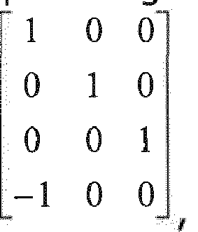
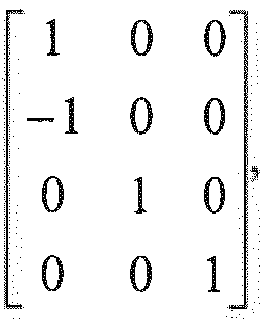
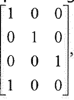
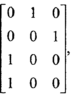
- the prestored codebook consists of 6 precoding matrix groups 1 0 0 X 0 0 0 1 0 0 0 1 , 1 0 0 0 1 0 X 0 0 0 0 1 , 1 0 0 0 1 0 0 0 1 X 0 0 , 0 1 0 1 0 0 0 X 0 0 0 0 1 , 0 1 0 1 0 0 0 0 1 , 0 1 0 1 0 0 0 0 1 X 0 0 , and 0 1 0 0 0 1 1 0 0 X 0 0 .
- the prestored codebook includes two precoding matrices selected from each of the 6 precoding matrix groups.
- the prestored codebook includes one precoding matrix having the X value of 1 in each of the 6 precoding matrix groups and the other precoding matrix having the X value of -1 in each of the 6 precoding matrix groups.
- the prestored codebook may include the following 12 precoding matrices of 1 0 0 1 0 0 0 1 0 0 0 1 , 1 0 0 ⁇ 1 0 0 0 1 0 0 0 1 , 1 0 0 0 1 0 1 0 0 0 1 , 1 0 0 0 1 0 ⁇ 1 0 0 0 0 1 , 1 0 0 0 0 1 0 0 0 1 0 0 , 1 0 0 0 1 0 0 1 0 0 , 1 0 0 0 1 0 0 0 1 ⁇ 1 0 0 , 0 1 0 1 0 0 1 0 0 0 0 1 , 0 1 0 1 0 1 0 0 0 0 1 , 0 1 0 1 0 1 0 0 0 0 1 , 0 1 0 1 0 0 0 ⁇ 1 0
- a user equipment (UE) for transmitting uplink signals via multiple antennas is defined by independent claim 3.
- the user equipment (UE) includes four antennas for transmitting and receiving signals, a memory for storing a codebook used for transmitting three layer signals via the four antennas, and a processor connected to the multiple antennas and the memory so as to process transmission of the uplink signals, wherein the processor includes a layer mapper for mapping the uplink signals to the three layers, a Discrete Fourier Transform (DFT) module for performing DFT spreading upon each of the three layer signals, a precoder for precoding the three DFT-spread layer signals received from the DFT module using a specific precoding matrix selected from among the codebook stored in the memory, and a transmission module for performing a predetermined process for constructing a Single Carrier - Frequency Division Multiple Access (SC-FDMA) symbol upon the precoded signals, and transmitting the processed signals to a Node BNode B via the four antennas, wherein the prestored code
- the memory stores, as the codebook, two precoding matrices from each of the 6 precoding matrix groups.
- the memory stores, as the codebook, both one precoding matrix having the X value of 1 in each of the 6 precoding matrix groups and the other precoding matrix having the X value of -1 in each of the 6 precoding matrix groups.
- the memory may store, as the codebook, 12 precoding matrices of 1 0 0 1 0 0 0 1 0 0 0 1 , 1 0 0 ⁇ 1 0 0 0 1 0 0 0 1 , 1 0 0 0 1 0 1 0 0 0 1 , 1 0 0 0 1 0 ⁇ 1 0 0 0 0 1 , 1 0 0 0 0 1 0 0 0 1 0 0 , 1 0 0 0 1 0 0 0 1 0 0 , 1 0 0 0 1 0 0 0 1 ⁇ 1 0 0 , 0 1 0 1 0 0 1 0 0 0 0 1 , 0 1 0 1 0 1 0 0 0 0 1 , 0 1 0 1 0 1 0 0 0 0 1 , 0 1 0 1 0 0 0 0 0
- a method for controlling a Node BNode B to receive uplink signals of a user equipment is defined by independent claim 5.
- the method includes receiving signals having been transmitted via four antennas and three layers from the user equipment (UE), and processing the received signals using a specific precoding matrix selected from among a prestored codebook, wherein the prestored codebook consists of 6 precoding matrix groups of 1 0 0 X 0 0 0 1 0 0 0 1 , 1 0 0 0 1 0 0 0 1 , 1 0 0 0 1 0 0 0 1 X 0 0 , 0 1 0 1 0 0 0 0 1 X 0 0 , 0 1 0 1 0 0 0 0 0 1 , 0 1 0 1 0 0 0 0 1 0 0 0 , and 0 1 0 0 0 1 1 0 0 X 0 0 .
- the prestored codebook may consists of 12 precoding matrices of 1 0 0 1 0 0 0 1 0 0 0 1 , 1 0 0 ⁇ 1 0 0 0 1 0 0 0 1 , 1 0 0 0 1 0 1 0 0 0 1 , 1 0 0 0 1 0 ⁇ 1 0 0 0 0 1 , 1 0 0 0 0 1 0 0 0 1 0 0 , 1 0 0 0 1 0 0 1 0 0 , 1 0 0 0 1 0 0 0 1 ⁇ 1 0 0 , 0 1 0 1 0 0 1 0 0 0 0 1 , 0 1 0 1 0 1 0 0 0 0 1 , 0 1 0 1 0 1 0 0 0 0 1 , 0 1 0 1 0 0 0 ⁇ 1 0
- a Node B for receiving uplink signals of a user equipment is defined by independent claim 6.
- the Node B includes one or multiple antennas for transmitting and receiving signals, a memory for storing a codebook used for receiving three layer signals transmitted by the UE via four antennas of the UE, and a processor connected to the antennas and the memory so as to process reception of the uplink signals, wherein the processor is configured to process the received signals using a specific precoding matrix selected from among the codebook stored in the memory, wherein the codebook consists of 6 precoding matrix groups of 1 0 0 X 0 0 0 1 0 0 0 1 , 1 0 0 0 1 0 0 0 1 , 1 0 0 0 1 0 0 0 1 X 0 0 , 0 1 0 1 0 0 0 0 1 , 0 1 0 1 0 0 0 0 1 , 0 1 0 1 0 0 0 0 1 , 0 1
- the memory may store, as the codebook, 12 precoding matrices of 1 0 0 1 0 0 0 1 0 0 0 1 , 1 0 0 ⁇ 1 0 0 0 1 0 0 0 1 , 1 0 0 0 1 0 1 0 0 0 1 , 1 0 0 0 1 0 ⁇ 1 0 0 0 0 1 , 1 0 0 0 0 1 0 0 0 1 0 0 , 1 0 0 0 1 0 0 0 1 0 0 , 1 0 0 0 1 0 0 0 1 ⁇ 1 0 0 , 0 1 0 1 0 0 1 0 0 0 0 1 , 0 1 0 1 0 1 0 0 0 0 1 , 0 1 0 1 0 1 0 0 0 0 1 , 0 1 0 1 0 0 0 0 0
- a method for transmitting and receiving uplink signals may transmit and receive using the above-mentioned optimized 4Tx rank 3 codebook, transmit uplink signals by reflecting a channel situation using a small amount of signaling overhead in various ways, and solve a PAPR problem.
- Peak power to Average Power Ratio is a parameter indicating characteristics of a waveform.
- PAPR is a specific value acquired when a peak amplitude of the waveform is divided by a time-averaged Root Mean Square (RMS) value of the waveform.
- RMS Root Mean Square
- PAPR is a dimensionless value.
- CM Cubic Metric
- An LTE-Advanced scheme can implement MIMO technology using Single Carrier - Frequency Division Multiple Access (SC-FDMA) so as to maintain a superior CM property.
- SC-FDMA Single Carrier - Frequency Division Multiple Access
- a signal including information corresponding to several layers is multiplexed and transmitted via a single antenna, so that the signal transmitted via this antenna may be considered to be a kind of multi-carrier signal.
- PAPR is associated with a dynamic range that must be supported by a power amplifier of a transmitter, and a CM value is another value capable of being used as a substitute for the PAPR.
- FIG. 2 shows a general structure of a transmitter based on MIMO technology.
- mapping information is mapped to each physical antenna by a precoding process, and is then transmitted via each physical antenna.
- FIG. 3 is a detailed block diagram illustrating the MIMO-based transmitter shown in FIG. 2 .
- the term 'codeword' indicates that Cyclic Redundancy Check (CRC) bits are attached to data information and are then encoded by a specific coding method.
- CRC Cyclic Redundancy Check
- coding methods for example, a turbo code, a tail biting convolution code, and the like.
- Each codeword is mapped to one or more layers (i.e., one or more virtual layers), and a total number of mapped layers is equal to a rank value. In other words, if a transmission rank is 3, a total number of transmission layers is also set to 3. Information mapped to each layer is precoded.
- data information mapped to each layer is mapped to a physical layer through a precoding process (where, the term 'layer' means a virtual layer as far as it especially designates a physical layer).
- Information is transmitted to each antenna via each physical layer.
- the precoding is carried out in a frequency domain, and an OFDM information transmission scheme is used for information mapped to the physical layer.
- the information mapped to the physical layer is mapped to a specific frequency domain, and is then IFFT - processed. After that, a cyclic prefix (CP) is attached to the IFFT result. Thereafter, information is transmitted to each antenna via a radio frequency (RF) chain.
- CP cyclic prefix
- the precoding process may be carried out by matrix multiplication.
- the number of rows is equal to the number of physical layers (i.e., the number of antennas), and the number of columns is equal to a rank value.
- the rank value is equal to the number of layers, so that the number of columns is equal to the number of layers.
- information mapped to a layer i.e., a virtual layer
- each element p ij of a (4 ⁇ 2) matrix is a weight used for precoding.
- y 1 , y 2 , y 3 , and y 4 are information mapped to physical layers, and are transmitted via respective antennas using individual OFDM transmission schemes.
- y 1 y 2 y 3 y 4 p 11 p 21 p 12 p 22 p 13 p 23 p 14 p 24 x 1 x 2
- a virtual layer will hereinafter be referred to as a layer so long as such use will not lead to confusion.
- An operation for mapping a virtual layer signal to a physical layer will hereinafter be considered to be an operation for directly mapping a layer to an antenna.
- the precoding method can be mainly classified into two methods, i.e., a wideband precoding method and a subband precoding method.
- the wideband precoding method is as follows. According to the wideband precoding method, when precoding is carried out in a frequency domain, the same precoding matrix is applied to all information transmitted to the frequency domain.
- FIG. 4 is a conceptual diagram illustrating a method for precoding information of each layer and transmitting the precoded information via an antenna.
- the subband precoding method is provided by the extension of the wideband precoding method.
- the subband precoding method applies a variety of precoding matrices to each subcarrier without applying the same precoding matrix to all subcarriers.
- a precoding matrix 'P' is used in a specific subcarrier
- another precoding matrix 'M' is used in the remaining subcarriers other than the specific subcarrier.
- element values of the precoding matrix 'P' are different from those of the other precoding matrix 'M'.
- Uplink signal transmission is relatively sensitive to PAPR or CM properties as compared to downlink signal transmission.
- SC-FDMA scheme is used for uplink signal transmission.
- FIG. 5 is a conceptual diagram illustrating a general SC-FDMA scheme.
- the OFDM scheme and the SC-FDMA scheme are considered to be identical to some extent with each other, because they convert a serial signal into parallel signals, map the parallel signals to subcarriers, perform an IDFT or IFFT process on the mapped signals, convert the IDFT- or IFFT- processed signals into a serial signal, attach a cyclic prefix (CP) to the resultant serial signal, and transmit the CP resultant signal via a radio frequency (RF) module.
- CP cyclic prefix
- the SC-FDMA scheme converts parallel signals into a serial signal, and performs DFT spreading upon the serial signal, so that it reduces the influence of a next IDFT or IFFT process and maintains a single signal characteristic of more than a predetermined level as much as possible.
- the reason why the CM value is degraded when a MIMO scheme is applied to uplink signal transmission is as follows. If a plurality of single-carrier signals each having good CM properties is simultaneously overlapped with each other, the overlapped signals may have poor CM properties. Therefore, if the SC-FDMA system multiplexes output information of several layers using a minimum number of single-carrier signals or one single-carrier signal on a single physical antenna, a transmission signal having a good CM can be generated.
- a codeword-layer mapping process may be performed before information to be transmitted is precoded. Since the SC-FDMA scheme is generally used for one transmission mode (1Tx), the number of layers is 1. However, if the SC-FDMA scheme supports a MIMO scheme, the number of layers is plural, and a codeword composed of a single transport block may be mapped to a plurality of layers.
- FIG. 6 is a conceptual diagram illustrating a method for mapping a codeword to several layers.
- a CM value may be increased. That is, because an output signal of a DFT block undergoes other processes before entering an IFFT module, i.e., because the output signal of the DFT block is divided into two layers, a CM value may be increased.
- FIG. 7 is a conceptual diagram illustrating a method for performing DFT upon each layer after performing codeword-to-layer mapping (i.e., a codeword-layer mapping) so as to prevent a CM value for each antenna from being increased.
- codeword-to-layer mapping i.e., a codeword-layer mapping
- a low CM value can be maintained. That is, the output signal of the DFT block is directly input to the IFFT block without passing through other processes, so that a low CM value can be maintained.
- a plurality of layers may share a single DFT block.
- a PAPR or a CM property may be deteriorated.
- the following embodiments of the present invention will describe a method for designing a codebook based on a precoding matrix by which only one layer signal is transmitted via a single antenna.
- the principle of designing a codebook that includes an appropriate number of precoding matrices and maximizes a chordal distance among precoding matrices of the codebook will hereinafter be described in detail.
- One embodiment of the present invention provides a method for generating a 4Tx - rank 3 codebook using 6 precoding matrices shown in the following Table 1.
- the equivalent precoding matrices shown in Table 1 generate the same Signal to Interference and Noise Ratio (SINR) value given a channel condition.
- SINR Signal to Interference and Noise Ratio
- FIG. 3 it is assumed that a codeword-to-layer mapping (also called a codeword-layer mapping) for use in rank 3 transmission is carried out as shown in FIG. 3 . That is, it is assumed that Codeword 1 is mapped to Layer 1 and Codeword 2 is equally mapped to Layer 2 and Layer 3 in units of a symbol.
- the precoding matrix for use in actual uplink signal transmission and reception is configured in a multiplication format in which each precoding matrix shown in Table 1 is multiplied by a specific constant.
- the constant multiplied by each precoding matrix will herein be omitted for convenience of description otherwise the constant is mentioned.
- the codebook shown in Table 1 may include a variety of precoding matrices according to X values of precoding matrices. If the X value is any one of QPSK alphabets (such as 1, -1, j and -j), the following precoding matrix groups may be obtained as represented by the following Table 2.
- Gr Equation Codebook subsets Gr1 1 0 0 X 0 0 0 1 0 0 1 1 0 0 1 0 0 0 1 0 0 0 1 , 1 0 0 ⁇ 1 0 0 0 1 0 0 0 1 , 1 0 0 j 0 0 0 0 1 0 0 0 1 , 1 0 0 ⁇ j 0 0 0 1 0 0 0 1 Gr2 1 0 0 0 1 0 0 0 1 X 0 0 0 0 0 1 1 0 0 0 1 0 1 0 0 0 0 1 , 1 0 0 0 0 1 0 ⁇ 1 0 0 0 0 1 , 1 0 0 0 1 0 0 1 0 0 1 , 1 0 0 0 1 0 0 1 0 0 1 , 1 0 0 0 1 0 0 1
- Table 2 illustrates that an X parameter of each precoding matrix group is denoted by X ⁇ ⁇ 1, ⁇ j ⁇ .
- One embodiment of the present invention provides a method for designing a codebook that includes a maximum chordal distance among precoding matrices contained in the codebook using the chordal distance concept and at the same time includes an optimized number of precoding matrices.
- FIG. 8 is a conceptual diagram illustrating a chordal distance.
- chordal distance is well known as one of norms (or standards) for comparing performances of various codebook sets.
- chordal indicates a straight line between two points located at the circumference. Therefore, given a two-dimensional (2D) case, a chordal distance indicates a distance between two points located at the circumference of a circle (e.g., a unit circle) as shown in FIG. 8 .
- a codebook including precoding matrices, each of which has a long chordal distance include a variety of precoding matrices to be used in different channel conditions.
- 2 trace
- a A H is the Frobenius norm of the matrix.
- the above-mentioned chordal distance can also be measured by the following equation 4.
- chordal distance among 6 precoding matrix groups can be calculated as follows.
- a chordal distance between a precoding matrix X i of the precoding matrix group Gr i and a precoding matrix X j of the precoding matrix group Gr j is dependent upon a trace ( X i X i H - X j X j H )( X i X i H - X j X j H ) H .
- This trace may reflect a distance between X i X i H and X j X j H .
- Xi is a precoding matrix belonging to the group i.
- a difference between a precoding matrix of the group 1 and a precoding matrix of another group can be represented by the following equation 6.
- X 1 X 1 H ⁇ X 2 X 2 H 1 2 0 x 1 * ⁇ x 2 * 0 x 1
- 2 X 1 X 1 H ⁇ X 4 X 4 H 1 2 ⁇ 1 x 1 * 0 0 x 1
- a difference between a precoding matrix of the group 2 and a precoding matrix of another group is represented by the following equation 7.
- X 2 X 2 H ⁇ X 3 X 3 H 1 2 0 0 x 2 * ⁇ x 3 * 0 0 0 0 x 2 0
- 2 X 2 X 2 H ⁇ X 4 X 4 H 1 2 ⁇ 1 0 x 2 * 0 0 1 ⁇ x 4 * 0 x 2 ⁇ x 4
- 2 0 0 0 0 0 0 X 2 X 2 H ⁇ X 5 X 5 H 1 2 ⁇ 1 0 x 2 * 0 0 1 0 ⁇ x 5 * x 2 0
- a difference between a precoding matrix of the group 3 and a precoding matrix of another group is represented by the following equation 8.
- X 3 X 3 H ⁇ X 4 X 4 H 1 2 ⁇ 1 0 0 x 3 * 0 1 ⁇ x 4 * 0 0 ⁇ x 4 2 ⁇
- 2 ⁇ 2 X 3 X 3 H ⁇ X 5 X 5 H 1 2 ⁇ 1 0 0 x 3 * 0 1 0 ⁇ x 5 * 0 0 0 0 x 3 ⁇ x 5 0
- 2 X 3 X 3 H ⁇ X 6 X 6 H 1 2 ⁇ 1 0 0 x 3 * 0 0 0 0 0 1 ⁇ x 6 * x 3 0 ⁇ x 6
- a difference between a precoding matrix of the group 4 and a precoding matrix of another group is represented by the following equation 9.
- X 4 X 4 H ⁇ X 5 X 5 H 1 2 0 0 0 0 0 x 4 * ⁇ x 5 * 0 x 4
- 2 X 4 X 4 H ⁇ X 6 X 6 H 1 2 0 0 0 0 ⁇ 1 x 4 * 0 0 x 4
- a difference between a precoding matrix of the group 5 and a precoding matrix of the group 6 is represented by the following equation 10.
- X 5 X 5 H ⁇ X 6 X 6 H 1 2 0 0 0 0 0 ⁇ 1 0 x 5 * 0 0 1 ⁇ x 6 * 0 x 5 ⁇ x 6
- Equations 6 to 10 are located in a unit circle.
- Equations 6 to 10 can be simplified as shown in the following equations 11 and 12.
- a difference matrix includes elements (+1, -1, x i , x i * , - x j and ⁇ x j * ) , ), each of which is not zero.
- a trace of the difference matrix X i X i H - X j X j H 3 2 as represented by the following equation 13.
- 2 1 2 1 4 ⁇ 1 + 1 + 1 + 1 + 1 + 1 + 1 + 1 + 1 + 1 + 1 + 1 + 1 + 1 + 1 + 1 + 1 + 1 + 1 + 1 + 1 + 1 + 1 + 1 + 1 + 1 + 1 + 1 + 1 + 1 + 1 + 1 + 1
- a difference matrix includes elements (+1, +1, -1, -1, x i , x i * , - x j and ⁇ x j * ) , ), each of which is not identical to zero.
- a trace of the difference matrix X i X i H - X j X j H becomes 1 as represented by the following equation 14.
- 2 1 2 1 4 ⁇ 2 + 2 + 1 + 1 + 1 + 1 + 1 + 1 + 1 + 1 + 1
- FIG. 9 illustrates the relationship of chordal distances among 6 precoding matrix groups according to one embodiment of the present invention.
- a chordal distance among different precoding matrices contained in same precoding matrix group i.e. group 1 (Gr 1) can be calculated as shown in the following Equation 15.
- 2 1 2 1 4 ⁇ 2
- 2 1 2 ⁇
- 2 1 2 ⁇
- 2 1 2 ⁇
- X 1 1 0 0 x 1 0 0 0 2 0 0 2 0 0 2 ⁇ Gr 1,
- Equation 15 a chordal distance among different precoding matrices contained in the Group 1 (Gr 1) is proportional to the distance among variables of individual precoding matrices. Therefore, as can be seen from Equation 16; a maximum chordal distance within the same group may be '1' as represented by the following equation 16.
- FIG. 10 illustrates conditions of variables for providing a maximum chordal distance within the same precoding matrix group.
- a precoding matrix including two variables having a phase difference of 180° therebetween may have a chordal distance of 1.
- the above-mentioned principle may also be equally applied to the remaining groups other than the group 1 (Gr 1), and the following theorem 2 may be derived.
- chordal distance As to a chordal distance between two precoding matrices contained in the same precoding matrix group, if variables of the precoding matrices have a phase difference of 180° therebetween, i.e., if variables of the precoding matrices are located at a diameter of a unit circle, the chordal distance of 1 can be obtained.
- Equation 16 it can be recognized that theorem 2 is achieved in the first group 1 (Gr 1), and the same conclusion may also be derived from other groups.
- a codebook subset for satisfying theorem 2 in the precoding matrix group 1 can be designed as represented by the following Table 3.
- Table 3 Codebook Subset 1 0 0 1 0 0 0 1 0 0 0 1 , 1 0 0 ⁇ 1 0 0 0 1 0 0 0 1
- a basic precoding matrix is denoted by 1 0 0 1 0 0 0 1 0 0 0 1 , and a codebook subset for satisfying the relationship between the basic precoding matrix and theorem 2 is illustrated.
- a codebook for implementing the maximum chordal distance may include an excessively small number of precoding matrices as necessary. Therefore, the following description assumes that variables contained in each precoding matrix group are denoted by QPSK alphabets, such that the chordal distance relationship can be represented by the following equation 17.
- FIG. 11 illustrates the relationship of chordal distances when a variable of a precoding matrix contained in the same precoding matrix group includes a QPSK alphabet.
- Equation 17 Equation 17
- FIG. 11 The following theorem 3 can be derived from Equation 17 and FIG. 11 .
- a chordal distance between two precoding matrices, each of which has a pair of variables (i.e., (1, -1), (-1, 1), (j, - j) or (-j, j)) within the same precoding matrix group, is denoted by 1
- a chordal distance between two precoding matrices, each of which has a pair of variables (i.e., (1, ⁇ j), (-1, ⁇ j) (j, ⁇ 1) or (-j, ⁇ 1)) within the same precoding matrix group is denoted by 1 2 .
- Theorem 3 may be demonstrated through Equation 17.
- an available chordal distance between precoding matrices shown in Table 2 may be any of 1, 3 2 and 1 2 .
- the 4Tx rank 3 codebook according to one embodiment of the present invention will hereinafter be described in detail.
- two precoding matrix groups satisfying a chordal distance of 1 can be selected from among 6 precoding matrix groups.
- the first group 1 (Gr 1) and the sixth group 6 (Gr 6) shown in Table 1 or 2 can be selected.
- the precoding matrices, which have a chordal distance of 1 within the same group according to theorem 2 or 3 correspond to only two precoding matrices, variables of which have a phase difference of 180° therebetween. Accordingly, it is assumed that two precoding matrices, variables of which have the relationship denoted by (1, -1), are selected from each group.
- the generated codebook is represented by the following table 4.
- a codebook, selected from table 2, that satisfies a chordal distance of 1 between two precoding matrices includes 4 precoding matrices.
- two precoding matrices e.g., precoding matrices having 1 and -1 as variables
- precoding matrices having 1 and -1 as variables each of which has a maximum chordal distance in each group, are selected from each of 6 groups shown in Table 1 using theorems 2 and 3, such that the 4Tx - rank 3 codebook can be given as shown in the following Table 5.
- Table 5 illustrates a codebook subset.
- Table 5 illustrates concepts of subsets related to rank 3 among codebooks of all ranks in the 4-antenna system including 4 antennas. From the viewpoint of rank 3, a codebook including 12 precoding matrices can be achieved.
- a User Equipment selects a specific precoding matrix (in which a predetermined constant for power control is multiplied by the specific precoding matrix) from among precoding matrices of the rank 3 codebook shown in Table 5, such that the UE can perform precoding and transmit signals using the selected precoding matrix.
- a specific precoding matrix in which a predetermined constant for power control is multiplied by the specific precoding matrix
- a user equipment (UE) for transmitting uplink signals using the above-mentioned codebook and a Node B for receiving the uplink signals from the UE will hereinafter be described in detail.
- FIG. 12 is a block diagram illustrating a general Node B and a general user equipment (UE).
- UE general user equipment
- a Node B 10 includes a processor 11, a memory 12, and a Radio Frequency (RF) unit 13.
- the RF unit 13 is used as a transmission/reception module for receiving an uplink signal and transmitting a downlink signal.
- the processor 11 may control downlink signal transmission using downlink signal transmission information (for example, a specific precoding matrix contained in a codebook for downlink signal transmission) stored in the memory 12. Otherwise, as an inverse process of the precoding process, the processor 11 may control a signal reception process by multiplying uplink signal reception information (e.g., an uplink signal) stored in the memory 12 by a Hermitian matrix of the same precoding matrix as a precoding matrix used in the UE 20.
- uplink signal reception information e.g., an uplink signal
- the UE 20 may include a processor 21, a memory 22, and an RF unit 23 used as a transmission/reception module for transmitting an uplink signal and receiving a downlink signal.
- the processor 21 may control uplink signal transmission using uplink signal transmission information (for example, a specific precoding matrix contained in the above-mentioned codebook for uplink signal transmission) stored in the memory 22. Otherwise, as an inverse process of the precoding process, the processor 21 may control a signal reception process by multiplying downlink signal reception information (e.g., a downlink signal) stored in the memory 22 by a Hermitian matrix of the same precoding matrix as a precoding matrix used in the UE 20.
- uplink signal transmission information for example, a specific precoding matrix contained in the above-mentioned codebook for uplink signal transmission
- the processor 21 may control a signal reception process by multiplying downlink signal reception information (e.g., a downlink signal) stored in the memory 22 by a Hermitian matrix of the same precoding matrix as
- a processor for transmitting a signal based on the SC-FDMA scheme in the 3GPP LTE system and a processor for transmitting a signal based on an OFDM scheme in the 3GPP LTE system will hereinafter be described, and a processor for enabling a UE to transmit an uplink signal using the SC-FDMA scheme as well as the MIMO scheme will then be described below.
- FIGS. 13 to 15 illustrate an SC-FDMA scheme for transmitting an uplink signal in the 3GPP LTE system and an OFDMA scheme for transmitting a downlink signal in the 3GPP LTE system.
- a UE for transmitting an uplink signal includes a Serial-to-Parallel converter 401, a subcarrier mapper 403, an M-point IDFT module 404, a Parallel-to-Serial converter 405, and the like.
- a UE for transmitting a signal using the SC-FDMA scheme further includes an N-point DFT module 402, and compensates for a predetermined part of the IDFT processing influence of the M-point IDFT module 404 so that a transmission signal can have single carrier characteristics.
- FIG. 14 shows the relationship between a block diagram for an uplink signal process prescribed in TS 36.211 including the 3GPP LTE system specification and a processor for transmitting a signal using the SC-FDMA scheme.
- each UE scrambles a transmission signal using a specific scrambling sequence so as to transmit an uplink signal, and the scrambled signal is modulated so that complex symbols are generated.
- transform precoding for performing a DFT spreading process on complex symbols is carried out. That is, a transform precoder prescribed in TS 36.211 may correspond to an N-point DFT module.
- the DFT-spread signal may be mapped to a specific resource element according to a resource block (RB) - based mapping rule by a resource element mapper, and it can be recognized that this operation corresponds to the subcarrier mapper shown in FIG. 13 .
- the signal mapped to the resource element is M-point IDFT or IFFT - processed by the SC-FDMA signal generator, parallel-to-serial conversion is performed on the IDFT or IFFT processed result, and then a cyclic prefix (CP) is added to the P/S conversion result.
- CP cyclic prefix
- FIG. 14 further shows a processor of a Node B that is used to receive a signal which has been received in the base station through the above-mentioned processes.
- the processor for SC-FDMA transmission in the 3GPP LTE system does not include a structure for utilizing the MIMO scheme. Therefore, the BS processor for MIMO transmission in the 3GPP LTE system will be described first, and a processor for transmitting an uplink signal by combining the SC-FDMA scheme with the MIMO scheme using the above BS processor will then be described.
- FIG. 15 is a block diagram illustrating a processor for enabling the Node B to transmit a downlink signal using the MIMO scheme in the 3GPP LTE system.
- a Node B in the 3GPP LTE system can transmit one or more codewords via a downlink. Therefore, one or more codewords may be processed as complex symbols by the scrambling module 301 and the modulation mapper 302 in the same manner as in the uplink operation shown in FIG. 12 . Thereafter, the complex symbols are mapped to a plurality of layers by the layer mapper 303, and each layer is multiplied by a predetermined precoding matrix selected according to the channel status and is then allocated to each transmission antenna by the precoding module 304. The processed transmission signals of individual antennas are mapped to time-frequency resource elements to be used for data transmission by the resource element mapper 305. Thereafter, the mapped result may be transmitted via each antenna after passing through the OFDM signal generator 306.
- a UE for transmitting an uplink signal via multiple antennas includes multiple antennas (not shown) for transmitting and receiving signals.
- the UE 20 includes a memory 22 for storing a codebook, and a processor 21 that are connected to multiple antennas (not shown) and the memory 22 so as to process uplink signal transmission.
- the codebook stored in the memory 22 includes precoding matrices shown in Table 5.
- the processor 21 of the UE configured as described above will hereinafter be described in detail.
- FIG. 16 illustrates a processor of the UE according to one embodiment of the present invention.
- the processor of the UE 20 includes a codeword to layer mapper 1401 for mapping uplink signals to a predetermined number of layers corresponding to a specific rank, a predetermined number of DFT modules 1402 for performing Discrete Fourier Transform (DFT) spreading on each of the predetermined number of layer signals, and a precoder 1403.
- the precoder 1403 selects a specific precoding matrix from a codebook comprised of 12 precoding matrices obtained when two precoding matrices including variables that have a phase difference of 180° therebetween are selected from each of 6 precoding matrix groups shown in Table 5, thereby precoding a DFT-spread resultant layer signal received from the DFT module 1402.
- each DFT module 1402 performs spreading of each layer signal
- this DFT module 1402 for spreading each layer signal is located just before the precoder 1403.
- the precoder 1403 performs precoding
- the precoder 1403 is configured such that each layer signal is mapped to one antenna and then transmitted via the mapped antenna, so that single carrier characteristics of each layer signal are maintained and good PAPR and CM properties are also maintained.
- the UE 20 further includes a transmission module.
- the transmission module performs a process constructing an SC-FDMA symbol upon the precoded signal, and transmits the resultant precoded signal to the Node B via multiple antennas 1405.
- the precoder 1403 selects a precoding matrix to be used for signal transmission from the codebook stored in the memory 22, and performs precoding on the selected precoding matrix.
- these precoding matrices may be precoding matrices established for equalizing transmission powers of multiple antennas and/or transmission powers of respective layers.
- the processor of the UE may further perform not only a layer shift function for periodically or aperiodically changing a layer mapped to a specific codeword but also an antenna shift function for periodically or aperiodically changing an antenna via which a specific layer signal is transmitted.
- the layer shift function may be performed by the layer mapper 1401 separately from the precoding of the precoder 1403, or may also be performed through column permutation of the precoding matrix when the precoder 1403 performs precoding.
- the antenna shift function may also be carried out separately from the precoding of the precoder 1403, or may also be performed through row permutation of the precoding matrix.
- the exemplary embodiments described hereinabove are combinations of elements and features of the present invention.
- the elements or features may be considered selective unless otherwise mentioned.
- Each element or feature may be practiced without being combined with other elements or features.
- the embodiments of the present invention may be constructed by combining parts of the elements and/or features. Operation orders described in the embodiments of the present invention may be rearranged. Some constructions or characteristics of any one embodiment may be included in another embodiment and may be replaced with corresponding constructions or characteristics of another embodiment. It is apparent that the present invention may be embodied by a combination of claims which do not have an explicit cited relation in the appended claims or may include new claims by amendment after application.
- the embodiments of the present invention may be achieved by various means, for example, hardware, firmware, software, or a combination thereof.
- the embodiments of the present invention may be implemented by one or more application specific integrated circuits (ASICs), digital signal processors (DSPs), digital signal processing devices (DSPDs), programmable logic devices (PLDs), field programmable gate arrays (FPGAs), processors, controllers, microcontrollers, microprocessors, etc.
- ASICs application specific integrated circuits
- DSPs digital signal processors
- DSPDs digital signal processing devices
- PLDs programmable logic devices
- FPGAs field programmable gate arrays
- processors controllers, microcontrollers, microprocessors, etc.
- the embodiments of the present invention may be achieved by a module, a procedure, a function, etc. performing the above-described functions or operations.
- Software code may be stored in a memory unit and driven by a processor.
- the memory unit may be located at the interior or exterior of the processor and may transmit data to and receive data from the processor via various known means.
- a method for transmitting and receiving uplink signals may transmit and receive using the above-mentioned optimized 4Tx Rank 3 codebook, transmit uplink signals by reflecting a channel situation using a small amount of signaling overhead in various ways, and solve a PAPR problem.
Description
- The present invention relates to a wireless mobile communication system, and more particularly to a communication system based on a Multiple Input Multiple Output (MIMO) scheme.
- MIMO technology is an abbreviation for Multiple Input Multiple Output technology. MIMO technology uses a plurality of transmission (Tx) antennas and a plurality of reception (Rx) antennas to improve the efficiency of transmission and reception (Tx/Rx) of data. In other words, MIMO technology allows a transmission end or reception end of a wireless communication system to use multiple antennas (hereinafter referred to as a multi-antenna), so that the capacity or performance can be improved. For convenience of description, the term "MIMO" can also be considered to be a multi-antenna technology.
- In more detail, MIMO technology is not dependent on a single antenna path to receive a message. Instead, the MIMO technology collects a plurality of data fragments received via several antennas, merges the collected data fragments, and completes total data. As a result, MIMO technology can increase a data transmission rate within a predetermined-sized cell region, or can increase system coverage while guaranteeing a specific data transmission rate. Under this situation, MIMO technology can be widely applied to mobile communication terminals, repeaters, or the like. MIMO technology can extend the range of data communication, so that it can overcome the limited amount of transmission data of mobile communication systems.
-
FIG. 1 is a block diagram illustrating a general MIMO communication system. - Referring to
FIG. 1 , the number of transmission (Tx) antennas in a transmitter is NT, and the number of reception (Rx) antennas in a receiver is NR. In this way, theoretical channel transmission capacity of the MIMO communication system when both the transmitter and the receiver use a plurality of antennas is greater than that of another case in which only the transmitter or the receiver uses several antennas. The theoretical channel transmission capacity of the MIMO communication system increases in proportion to the number of antennas. Therefore, data transmission rate and frequency efficiency are greatly increased. Provided that a maximum data transmission rate acquired when a single antenna is used is set to Ro, a data transmission rate acquired when multiple antennas are used can theoretically increase by a predetermined amount that corresponds to the single antenna data transmission rate (Ro) multiplied by a rate of increase Ri. The rate of increase (Ri) can be represented by the followingequation 1.
- For example, provided that a MIMO system uses four transmission (Tx) antennas and four reception (Rx) antennas, the MIMO system can theoretically acquire a high data transmission rate which is four times higher than that of a single antenna system. After the above-mentioned theoretical capacity increase of the MIMO system was demonstrated in the mid-1990s, many developers began to conduct intensive research into a variety of technologies which can substantially increase a data transmission rate using the theoretical capacity increase. Some of the above technologies have been reflected in a variety of wireless communication standards, for example, a third-generation mobile communication or a next-generation wireless LAN, etc. The above-mentioned MIMO technology can be classified into a spatial diversity scheme (also called a Transmit Diversity scheme) and a spatial multiplexing scheme. The spatial diversity scheme increases transmission reliability using symbols passing various channel paths. The spatial multiplexing scheme simultaneously transmits a plurality of data symbols via a plurality of transmission (Tx) antennas, so that it increases a transmission rate of data. In addition, the combination of the spatial diversity scheme and the spatial multiplexing scheme has also been recently developed to properly acquire unique advantages of the two schemes.
- In association with the MIMO technology, a variety of MIMO-associated technologies have been intensively researched by many companies or developers, for example, research into an information theory associated with a MIMO communication capacity calculation under various channel environments or multiple access environments, research into radio frequency (RF) channel measurement and modeling of the MIMO system, and research into a space-time signal processing technology for increasing transmission reliability and data transmission rate.
- In a 3rd Generation Partnership Project Long Term Evolution (3GPP LTE) system, the above-mentioned MIMO scheme is applied to only downlink signal transmission of the 3GPP LTE system. The MIMO technology may also be extended to uplink signal transmission. In this case, a transmitter structure should be changed to implement the MIMO technology, so that a Peak power to Average Power Ratio (PAPR) or Cubic Metric (CM) characteristics may be deteriorated. Therefore, there is needed a new technology capable of effectively applying the MIMO scheme to uplink signal transmission.
- Specifically, an appropriate number of precoding matrices are selected from a codebook for use in
uplink rank 3 transmission, and at the same time it is necessary for the codebook to maximize a chordal distance between precoding matrices. - Document
US 2008/0292013 A1 discloses a transmitter, a receiver and methods of operating a transmitter and a receiver. The transmitter is for use with NT transmit antennas and includes a precoder unit configured to precode data for transmission using a preceding matrix selected from a nested codebook, wherein the nested codebook provides codebooks corresponding to different transmission layers that are derived from column subsets of multiple NTxNT preceding matrices. The transmitter also includes a transmit unit configured to transmit the precoded data. - Accordingly, the present invention is directed to an uplink signal transmission and method using an optimized
rank 3 codebook that substantially obviates one or more problems due to limitations and disadvantages of the related art. - Additional advantages, objects, and features of the invention will be set forth in part in the description which follows and in part will become apparent to those having ordinary skill in the art upon examination of the following or may be learned from practice of the invention. The objectives and other advantages of the invention may be realized and attained by the structure particularly pointed out in the written description and claims hereof as well as the appended drawings.
- To achieve these objects and other advantages and in accordance with the purpose of the invention, as embodied and broadly described herein, a method for controlling a user
equipment (UE) to transmit uplink signals via four antennas is defined byindependent claim 1. The method includes mapping the uplink signals to three layers; performing Discrete Fourier Transform (DFT) spreading upon each of signals of the three layers, precoding the three DFT- spread layer signals using a specific precoding matrix selected from among a prestored codebook, performing a predetermined process for constructing a Single Carrier - Frequency Division Multiple Access (SC-FDMA) symbol upon the precoded signals, and transmitting the SC-FDMA symbol to a Node B, i.e. Node B via the four antennas, wherein the prestored codebook consists of 6precoding matrix groups 


- The prestored codebook includes two precoding matrices selected from each of the 6 precoding matrix groups.
- The prestored codebook includes one precoding matrix having the X value of 1 in each of the 6 precoding matrix groups and the other precoding matrix having the X value of -1 in each of the 6 precoding matrix groups.
- The prestored codebook may include the following 12 precoding matrices of


- In another aspect of the present invention, a user equipment (UE) for transmitting uplink signals via multiple antennas is defined by
independent claim 3. The user equipment (UE) includes four antennas for transmitting and receiving signals, a memory for storing a codebook used for transmitting three layer signals via the four antennas, and a processor connected to the multiple antennas and the memory so as to process transmission of the uplink signals, wherein the processor includes a layer mapper for mapping the uplink signals to the three layers, a Discrete Fourier Transform (DFT) module for performing DFT spreading upon each of the three layer signals, a precoder for precoding the three DFT-spread layer signals received from the DFT module using a specific precoding matrix selected from among the codebook stored in the memory, and a transmission module for performing a predetermined process for constructing a Single Carrier - Frequency Division Multiple Access (SC-FDMA) symbol upon the precoded signals, and transmitting the processed signals to a Node BNode B via the four antennas, wherein the prestored codebook consists of 6 precoding matrix groups of


- The memory stores, as the codebook, two precoding matrices from each of the 6 precoding matrix groups. The memory stores, as the codebook, both one precoding matrix having the X value of 1 in each of the 6 precoding matrix groups and the other precoding matrix having the X value of -1 in each of the 6 precoding matrix groups.
- The memory may store, as the codebook, 12 precoding matrices of


- In another aspect of the present invention, a method for controlling a Node BNode B to receive uplink signals of a user equipment (UE) is defined by independent claim 5. The method includes receiving signals having been transmitted via four antennas and three layers from the user equipment (UE), and processing the received signals using a specific precoding matrix selected from among a prestored codebook, wherein the prestored codebook consists of 6 precoding matrix groups of


- The prestored codebook may consists of 12 precoding matrices of


- In another aspect of the present invention, a Node B for receiving uplink signals of a user equipment (UE) is defined by independent claim 6. The Node B includes one or multiple antennas for transmitting and receiving signals, a memory for storing a codebook used for receiving three layer signals transmitted by the UE via four antennas of the UE, and a processor connected to the antennas and the memory so as to process reception of the uplink signals, wherein the processor is configured to process the received signals using a specific precoding matrix selected from among the codebook stored in the memory, wherein the codebook consists of 6 precoding matrix groups of


- The memory may store, as the codebook, 12 precoding matrices of


- As described above, a method for transmitting and receiving uplink signals according to the embodiments of the present invention may transmit and receive using the above-mentioned optimized
4Tx rank 3 codebook, transmit uplink signals by reflecting a channel situation using a small amount of signaling overhead in various ways, and solve a PAPR problem. It is to be understood that both the foregoing general description and the following detailed description of the present invention are exemplary and explanatory and are intended to provide further explanation of the invention as claimed. - The accompanying drawings, which are included to provide a further understanding of the invention and are incorporated in and constitute a part of this application, illustrate embodiment(s) of the invention and together with the description serve to explain the principle of the invention. In the drawings:
-
FIG. 1 is a conceptual diagram illustrating a general MIMO communication system. -
FIG. 2 illustrates a general structure of a transmitter based on MIMO technology. -
FIG. 3 is a detailed diagram illustrating the general structure shown inFIG. 2 . -
FIG. 4 is a conceptual diagram illustrating a method for precoding information of each layer and transmitting the precoded information via an antenna. -
FIG. 5 is a conceptual diagram illustrating a general SC-FDMA scheme. -
FIG. 6 is a conceptual diagram illustrating a method for mapping a codeword to several layers. -
FIG. 7 is a conceptual diagram illustrating a method for performing DFT upon each layer after performing codeword-to-layer mapping (i.e., codeword-layer mapping) so as to prevent a CM value for each antenna from being increased. -
FIG. 8 is a conceptual diagram illustrating a chordal distance. -
FIG. 9 illustrates the relationship of chordal distances among 6 precoding matrix groups according to one embodiment of the present invention. -
FIG. 10 illustrates conditions of variables for providing a maximum chordal distance within the same precoding matrix group. -
FIG. 11 illustrates the relationship of chordal distances when a variable of a precoding matrix contained in the same precoding matrix group includes a Quadrature Phase Shift Keying (QPSK) alphabet. -
FIG. 12 is a block diagram illustrating a general Node B and a general user equipment (UE). -
FIGS. 13 to 15 illustrate an SC-FDMA scheme for transmitting an uplink signal in a 3GPP LTE system and an OFDMA scheme for transmitting a downlink signal in the 3GPP LTE system. -
FIG. 16 illustrates a processor of a UE according to one embodiment of the present invention. - Reference will now be made in detail to the preferred embodiments of the present invention, examples of which are illustrated in the accompanying drawings. Wherever possible, the same reference numbers will be used throughout the drawings to refer to the same or like parts.
- The detailed description, which will be given below with reference to the accompanying drawings, is intended to explain exemplary embodiments of the present invention, rather than to show the only embodiments that can be implemented according to the present invention. The following detailed description includes specific details in order to provide a thorough understanding of the present invention. However, it will be apparent to those skilled in the art that the present invention may be practiced without such specific details. For example, the following description will be given centering on specific terms, but the present invention is not limited thereto and any other terms may be used to represent the same meanings. Also, wherever possible, the same reference numbers will be used throughout the drawings to refer to the same or like parts. Peak power to Average Power Ratio (PAPR) is a parameter indicating characteristics of a waveform. PAPR is a specific value acquired when a peak amplitude of the waveform is divided by a time-averaged Root Mean Square (RMS) value of the waveform. PAPR is a dimensionless value. In general, a PAPR of a single carrier signal is better than that of a multi-carrier signal. Cubic Metric (CM) is another specific value to describe a waveform characteristic which is similar to PAPR.
- An LTE-Advanced scheme can implement MIMO technology using Single Carrier - Frequency Division Multiple Access (SC-FDMA) so as to maintain a superior CM property. When using general precoding, a signal including information corresponding to several layers is multiplexed and transmitted via a single antenna, so that the signal transmitted via this antenna may be considered to be a kind of multi-carrier signal. PAPR is associated with a dynamic range that must be supported by a power amplifier of a transmitter, and a CM value is another value capable of being used as a substitute for the PAPR.
-
FIG. 2 shows a general structure of a transmitter based on MIMO technology. - In
FIG. 2 , one or more codewords are mapped to a plurality of layers. In this case, mapping information is mapped to each physical antenna by a precoding process, and is then transmitted via each physical antenna. -
FIG. 3 is a detailed block diagram illustrating the MIMO-based transmitter shown inFIG. 2 . - The term 'codeword' indicates that Cyclic Redundancy Check (CRC) bits are attached to data information and are then encoded by a specific coding method. There are a variety of coding methods, for example, a turbo code, a tail biting convolution code, and the like. Each codeword is mapped to one or more layers (i.e., one or more virtual layers), and a total number of mapped layers is equal to a rank value. In other words, if a transmission rank is 3, a total number of transmission layers is also set to 3. Information mapped to each layer is precoded. In this case, data information mapped to each layer is mapped to a physical layer through a precoding process (where, the term 'layer' means a virtual layer as far as it especially designates a physical layer). Information is transmitted to each antenna via each physical layer. Under the condition that no specified explanation is shown in
FIG. 3 , the precoding is carried out in a frequency domain, and an OFDM information transmission scheme is used for information mapped to the physical layer. The information mapped to the physical layer is mapped to a specific frequency domain, and is then IFFT - processed. After that, a cyclic prefix (CP) is attached to the IFFT result. Thereafter, information is transmitted to each antenna via a radio frequency (RF) chain. - The precoding process may be carried out by matrix multiplication. In each of the matrices, the number of rows is equal to the number of physical layers (i.e., the number of antennas), and the number of columns is equal to a rank value. The rank value is equal to the number of layers, so that the number of columns is equal to the number of layers. Referring to the
following equation 2, information mapped to a layer (i.e., a virtual layer) is x1 and x2, each element pij of a (4 × 2) matrix is a weight used for precoding. y1, y2, y3, and y4 are information mapped to physical layers, and are transmitted via respective antennas using individual OFDM transmission schemes.
- In the following description, a virtual layer will hereinafter be referred to as a layer so long as such use will not lead to confusion. An operation for mapping a virtual layer signal to a physical layer will hereinafter be considered to be an operation for directly mapping a layer to an antenna.
- The precoding method can be mainly classified into two methods, i.e., a wideband precoding method and a subband precoding method.
- The wideband precoding method is as follows. According to the wideband precoding method, when precoding is carried out in a frequency domain, the same precoding matrix is applied to all information transmitted to the frequency domain.
-
FIG. 4 is a conceptual diagram illustrating a method for precoding information of each layer and transmitting the precoded information via an antenna. - Referring to
FIG. 4 , it can be recognized that information corresponding to a plurality of layers is precoded while being classified according to subcarriers of each frequency domain, and the precoded information is transmitted via each antenna. All precoding matrices 'P' in the wideband precoding method are equal to each other. - The subband precoding method is provided by the extension of the wideband precoding method. The subband precoding method applies a variety of precoding matrices to each subcarrier without applying the same precoding matrix to all subcarriers. In other words, according to the subband precoding method, a precoding matrix 'P' is used in a specific subcarrier, and another precoding matrix 'M' is used in the remaining subcarriers other than the specific subcarrier. Herein, element values of the precoding matrix 'P' are different from those of the other precoding matrix 'M'.
- Uplink signal transmission is relatively sensitive to PAPR or CM properties as compared to downlink signal transmission.
- The increase of power amplifier costs caused by the increase of PAPR or CM properties may generate more serious problems in a user equipment (UE). Thus, the SC-FDMA scheme is used for uplink signal transmission.
-
FIG. 5 is a conceptual diagram illustrating a general SC-FDMA scheme. - As shown in
FIG. 5 , the OFDM scheme and the SC-FDMA scheme are considered to be identical to some extent with each other, because they convert a serial signal into parallel signals, map the parallel signals to subcarriers, perform an IDFT or IFFT process on the mapped signals, convert the IDFT- or IFFT- processed signals into a serial signal, attach a cyclic prefix (CP) to the resultant serial signal, and transmit the CP resultant signal via a radio frequency (RF) module. However, in contrast to the OFDM scheme, the SC-FDMA scheme converts parallel signals into a serial signal, and performs DFT spreading upon the serial signal, so that it reduces the influence of a next IDFT or IFFT process and maintains a single signal characteristic of more than a predetermined level as much as possible. - In the meantime, the reason why the CM value is degraded when a MIMO scheme is applied to uplink signal transmission is as follows. If a plurality of single-carrier signals each having good CM properties is simultaneously overlapped with each other, the overlapped signals may have poor CM properties. Therefore, if the SC-FDMA system multiplexes output information of several layers using a minimum number of single-carrier signals or one single-carrier signal on a single physical antenna, a transmission signal having a good CM can be generated.
- A codeword-layer mapping process may be performed before information to be transmitted is precoded. Since the SC-FDMA scheme is generally used for one transmission mode (1Tx), the number of layers is 1. However, if the SC-FDMA scheme supports a MIMO scheme, the number of layers is plural, and a codeword composed of a single transport block may be mapped to a plurality of layers.
-
FIG. 6 is a conceptual diagram illustrating a method for mapping a codeword to several layers. - Referring to
FIG. 6 , if the codeword-layer mapping is carried out after a DFT process for the SC-FDMA scheme is performed, a CM value may be increased. That is, because an output signal of a DFT block undergoes other processes before entering an IFFT module, i.e., because the output signal of the DFT block is divided into two layers, a CM value may be increased. -
FIG. 7 is a conceptual diagram illustrating a method for performing DFT upon each layer after performing codeword-to-layer mapping (i.e., a codeword-layer mapping) so as to prevent a CM value for each antenna from being increased. - Therefore, if the number of DFT blocks is changed while being classified according to layer numbers based on a rank value, a low CM value can be maintained. That is, the output signal of the DFT block is directly input to the IFFT block without passing through other processes, so that a low CM value can be maintained. In the case of actual implementation, a plurality of layers may share a single DFT block.
- If a plurality of layer signals is transmitted via a single antenna by applying the MIMO scheme to uplink signal transmission, a PAPR or a CM property may be deteriorated. In order to overcome the above-mentioned problem, the following embodiments of the present invention will describe a method for designing a codebook based on a precoding matrix by which only one layer signal is transmitted via a single antenna. In addition, the principle of designing a codebook that includes an appropriate number of precoding matrices and maximizes a chordal distance among precoding matrices of the codebook will hereinafter be described in detail.
- Next, a chordal distance will firstly be described, and an uplink codebook (specifically, a codebook for use in both 4-antenna and
Rank 3 transmission) and a method for transmitting and receiving a signal using the codebook will hereinafter be described in detail. - One embodiment of the present invention provides a method for generating a 4Tx -
rank 3 codebook using 6 precoding matrices shown in the following Table 1. The equivalent precoding matrices shown in Table 1 generate the same Signal to Interference and Noise Ratio (SINR) value given a channel condition. In the following embodiments, it is assumed that a codeword-to-layer mapping (also called a codeword-layer mapping) for use inrank 3 transmission is carried out as shown inFIG. 3 . That is, it is assumed thatCodeword 1 is mapped toLayer 1 andCodeword 2 is equally mapped toLayer 2 andLayer 3 in units of a symbol.[Table 1] Group General codebook form Equivalent precoding matrices 1 

2 

3 

4 

5 

6 

- The precoding matrix for use in actual uplink signal transmission and reception is configured in a multiplication format in which each precoding matrix shown in Table 1 is multiplied by a specific constant. In the following description, the constant multiplied by each precoding matrix will herein be omitted for convenience of description otherwise the constant is mentioned.
- In the meantime, it can be shown that permutation between specific columns does not affect SINR performance. For example, although a precoding matrix [C1, C2, C3] is modified into another precoding matrix [C1, C3, C2], this modification is considered to merely be codeword swapping, and has no change in total sum of resultant SINR values. In the following description, only "General Codebook Form" in each of 6 precoding matrix groups shown in Table 1 will hereinafter be described, but equivalent precoding matrices will not be described.
- On the other hand, the codebook shown in Table 1 may include a variety of precoding matrices according to X values of precoding matrices. If the X value is any one of QPSK alphabets (such as 1, -1, j and -j), the following precoding matrix groups may be obtained as represented by the following Table 2.
[Table 2] Gr Equation Codebook subsets Gr1 

Gr2 

Gr3 

Gr4 

Gr5 
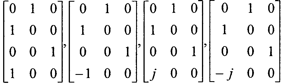
Gr6 

- Table 2 illustrates that an X parameter of each precoding matrix group is denoted by X ∈ {±1,±j}.
- The above-mentioned method for using the entirety of the precoding matrices as a 4Tx -
rank 3 codebook can also be used. One embodiment of the present invention provides a method for designing a codebook that includes a maximum chordal distance among precoding matrices contained in the codebook using the chordal distance concept and at the same time includes an optimized number of precoding matrices. -
FIG. 8 is a conceptual diagram illustrating a chordal distance. - A chordal distance is well known as one of norms (or standards) for comparing performances of various codebook sets. Herein, the term "chordal" indicates a straight line between two points located at the circumference. Therefore, given a two-dimensional (2D) case, a chordal distance indicates a distance between two points located at the circumference of a circle (e.g., a unit circle) as shown in
FIG. 8 . Generally, it is preferable that a codebook including precoding matrices, each of which has a long chordal distance, include a variety of precoding matrices to be used in different channel conditions. - There is a need for the 4Tx - codebook to consider a four-dimensional chordal distance, so that the
following equation 3 can be used as a chordal distance for selecting a codebook set.
- In
Equation 3, P is P = [v 1 v 2 ··· vN ], and Q is Q = [u 1 u 2 ··· uN ], where vi and ui (i = 1,2,···N, N =4 in the case of 4Tx antennas) are principal vectors of the matrices P and Q, respectively. In addition,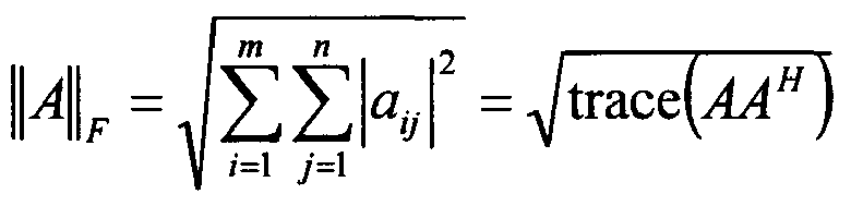
following equation 4.
- First, the chordal distance among 6 precoding matrix groups can be calculated as follows.
- A chordal distance between a precoding matrix X i of the precoding matrix group Gr i and a precoding matrix X j of the precoding matrix group Gr j is dependent upon a trace (XiXi H - XjXj H )(XiXi H - XjXj H ) H . This trace may reflect a distance between XiXi H and XjXj H . The number of cases in which two pairs are selected from among the above 6 groups is set to a relatively high number, e.g.,
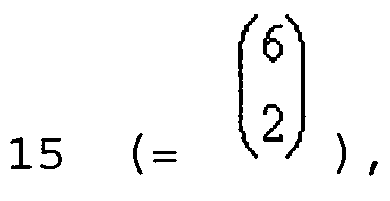

- In Equation 5, Xi is a precoding matrix belonging to the group i. A difference between a precoding matrix of the
group 1 and a precoding matrix of another group can be represented by the following equation 6.
- A difference between a precoding matrix of the
group 2 and a precoding matrix of another group is represented by the following equation 7.
- In addition, a difference between a precoding matrix of the
group 3 and a precoding matrix of another group is represented by the following equation 8.
- In addition, a difference between a precoding matrix of the
group 4 and a precoding matrix of another group is represented by the following equation 9.
- Finally, a difference between a precoding matrix of the group 5 and a precoding matrix of the group 6 is represented by the following
equation 10.
- It should be noted that variables shown in Equations 6 to 10 are located in a unit circle. In addition, Equations 6 to 10 can be simplified as shown in the following
equations 11 and 12.

- The numbers of zero values in a difference XiXi H - XjXj H between different matrices of
Equation 11 are the same when (i,j)≠(1,6),(6,1),(2,5),(5,2),(3,4) or (4,3), but the individual zero values have different positions. In more detail, under the case of (i,j)≠(1,6),(6,1),(2,5),(5,2),(3,4) or (4,3), a difference matrix includes elements (+1, -1, xi ,


equation 13.

- On the other hand, the numbers of zero values in a difference XiXi H - XjXj H between different matrices of Equation 12 are the same when (i,j)=(1,6),(6,1),(2,5)(5,2),(3,4) or (4,3), but the individual 0 values have different positions. In more detail, under the case of (i,j)=(1,6),(6,1),(2,5),(5,2),(3,4) or (4,3), a difference matrix includes elements (+1, +1, -1, -1, xi ,


- If the pair of groups shown in
Equations 13 and 14 satisfies (i,j) = (1,6), (6,1), (2,5), (5,2), (3,4) or (4,3), a chordal distance of 1 is provided;otherwise, a chordal distance of
-
FIG. 9 illustrates the relationship of chordal distances among 6 precoding matrix groups according to one embodiment of the present invention. - The following theorem can be derived using the relationship shown in
FIG. 9 . - If a pair of groups shown in Table 2 satisfies (i,j) = (1,6), (6,1), (2,5), (5,2), (3,4) or (4,3), a chordal distance of 1 is provided. If a pair of groups shown in Table 2 satisfies (i,j) ≠ (1,6), (6,1), (2,5), (5,2), (3,4) or (4,3), a chordal distance of

- On the other hand, the relationship of chordal distances among precoding matrices of the precoding matrix group shown in Table 2 will hereinafter be described in detail.
- First, a chordal distance among different precoding matrices contained in same precoding matrix group, i.e. group 1 (Gr 1) can be calculated as shown in the following Equation 15.


- As can be seen from Equation 15, a chordal distance among different precoding matrices contained in the Group 1 (Gr 1) is proportional to the distance among variables of individual precoding matrices. Therefore, as can be seen from Equation 16; a maximum chordal distance within the same group may be '1' as represented by the following equation 16.

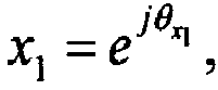
y1 , θ 1 = θ x1 - θ y1 - In order to implement the maximum chordal distance, it is necessary for variables contained in each precoding matrix to satisfy the relationship shown in
FIG. 10 . -
FIG. 10 illustrates conditions of variables for providing a maximum chordal distance within the same precoding matrix group. - In other words, a precoding matrix including two variables having a phase difference of 180° therebetween may have a chordal distance of 1. The above-mentioned principle may also be equally applied to the remaining groups other than the group 1 (Gr 1), and the following
theorem 2 may be derived. - In Table 2, as to a chordal distance between two precoding matrices contained in the same precoding matrix group, if variables of the precoding matrices have a phase difference of 180° therebetween, i.e., if variables of the precoding matrices are located at a diameter of a unit circle, the chordal distance of 1 can be obtained.
- As can be seen from Equation 16, it can be recognized that
theorem 2 is achieved in the first group 1 (Gr 1), and the same conclusion may also be derived from other groups. - As an application of
theorem 2, a codebook subset forsatisfying theorem 2 in theprecoding matrix group 1 can be designed as represented by the following Table 3.[Table 3] Codebook Subset 
- In Table 3, a basic precoding matrix is denoted by

theorem 2 is illustrated. However, it should be noted that a variety of subsets may be designed according to methods for selecting such a basic precoding matrix using the same principles as described above. In this case, a codebook for implementing the maximum chordal distance may include an excessively small number of precoding matrices as necessary. Therefore, the following description assumes that variables contained in each precoding matrix group are denoted by QPSK alphabets, such that the chordal distance relationship can be represented by the following equation 17.
-
FIG. 11 illustrates the relationship of chordal distances when a variable of a precoding matrix contained in the same precoding matrix group includes a QPSK alphabet. - The following
theorem 3 can be derived from Equation 17 andFIG. 11 . - A chordal distance between two precoding matrices, each of which has a pair of variables (i.e., (1, -1), (-1, 1), (j, - j) or (-j, j)) within the same precoding matrix group, is denoted by 1, a chordal distance between two precoding matrices, each of which has a pair of variables (i.e., (1, ±j), (-1, ±j) (j, ±1) or (-j, ±1)) within the same precoding matrix group, is denoted by

-
Theorem 3 may be demonstrated through Equation 17. - As can be seen from
theorems 1 to 3, an available chordal distance between precoding matrices shown in Table 2 may be any of 1,

4Tx rank 3 codebook according to one embodiment of the present invention will hereinafter be described in detail. - In accordance with this embodiment of the present invention, considering that a maximum chordal distance between two precoding matrices is set to 1 on the basis of the above-mentioned
theorems 1 to 3, a method for designing a codebook having only precoding matrices having a chordal distance of 1 therebetween will hereinafter be described in detail. - Based on
theorem 1, two precoding matrix groups satisfying a chordal distance of 1 can be selected from among 6 precoding matrix groups. As one embodiment of the present invention, the first group 1 (Gr 1) and the sixth group 6 (Gr 6) shown in Table 1 or 2 can be selected. In addition, the precoding matrices, which have a chordal distance of 1 within the same group according totheorem [Table 4] Codebook subset 
- A codebook, selected from table 2, that satisfies a chordal distance of 1 between two precoding matrices includes 4 precoding matrices.
- As can be seen from
Corollary 1, in the case where the codebook is comprised of only precoding matrices having a maximum chordal distance of 1 in consideration of only the chordal distance, only four precoding matrices can be obtained, and thus it is difficult to reflect a variety of channel statuses using only the four precoding matrices. Therefore, a specific case in which a second highest chordal distance value of
theorems rank 3 codebook can be given as shown in the following Table 5.[Table 5] Codebook subset 
- Table 5 illustrates a codebook subset. In more detail, Table 5 illustrates concepts of subsets related to
rank 3 among codebooks of all ranks in the 4-antenna system including 4 antennas. From the viewpoint ofrank 3, a codebook including 12 precoding matrices can be achieved. - In accordance with one embodiment of the present invention, a User Equipment (UE) selects a specific precoding matrix (in which a predetermined constant for power control is multiplied by the specific precoding matrix) from among precoding matrices of the
rank 3 codebook shown in Table 5, such that the UE can perform precoding and transmit signals using the selected precoding matrix. - On the other hand, a user equipment (UE) for transmitting uplink signals using the above-mentioned codebook and a Node B for receiving the uplink signals from the UE will hereinafter be described in detail.
-
FIG. 12 is a block diagram illustrating a general Node B and a general user equipment (UE). - Referring to
FIG. 12 , aNode B 10 includes aprocessor 11, a memory 12, and a Radio Frequency (RF)unit 13. TheRF unit 13 is used as a transmission/reception module for receiving an uplink signal and transmitting a downlink signal. Theprocessor 11 may control downlink signal transmission using downlink signal transmission information (for example, a specific precoding matrix contained in a codebook for downlink signal transmission) stored in the memory 12. Otherwise, as an inverse process of the precoding process, theprocessor 11 may control a signal reception process by multiplying uplink signal reception information (e.g., an uplink signal) stored in the memory 12 by a Hermitian matrix of the same precoding matrix as a precoding matrix used in the UE 20. - The UE 20 may include a
processor 21, amemory 22, and anRF unit 23 used as a transmission/reception module for transmitting an uplink signal and receiving a downlink signal. Theprocessor 21 may control uplink signal transmission using uplink signal transmission information (for example, a specific precoding matrix contained in the above-mentioned codebook for uplink signal transmission) stored in thememory 22. Otherwise, as an inverse process of the precoding process, theprocessor 21 may control a signal reception process by multiplying downlink signal reception information (e.g., a downlink signal) stored in thememory 22 by a Hermitian matrix of the same precoding matrix as a precoding matrix used in the UE 20. - In the meantime, a detailed description about a processor of the UE 20 (or the BS 10), particularly, a structure for transmitting a signal using the SC-FDMA scheme, will hereinafter be described. A processor for transmitting a signal based on the SC-FDMA scheme in the 3GPP LTE system and a processor for transmitting a signal based on an OFDM scheme in the 3GPP LTE system will hereinafter be described, and a processor for enabling a UE to transmit an uplink signal using the SC-FDMA scheme as well as the MIMO scheme will then be described below.
-
FIGS. 13 to 15 illustrate an SC-FDMA scheme for transmitting an uplink signal in the 3GPP LTE system and an OFDMA scheme for transmitting a downlink signal in the 3GPP LTE system. - Referring to
FIG. 13 , not only a UE for transmitting an uplink signal but also a Node B for transmitting a downlink signal includes a Serial-to-Parallel converter 401, asubcarrier mapper 403, an M-point IDFT module 404, a Parallel-to-Serial converter 405, and the like. However, a UE for transmitting a signal using the SC-FDMA scheme further includes an N-point DFT module 402, and compensates for a predetermined part of the IDFT processing influence of the M-point IDFT module 404 so that a transmission signal can have single carrier characteristics. -
FIG. 14 shows the relationship between a block diagram for an uplink signal process prescribed in TS 36.211 including the 3GPP LTE system specification and a processor for transmitting a signal using the SC-FDMA scheme. In accordance with TS 36.211, each UE scrambles a transmission signal using a specific scrambling sequence so as to transmit an uplink signal, and the scrambled signal is modulated so that complex symbols are generated. After that, transform precoding for performing a DFT spreading process on complex symbols is carried out. That is, a transform precoder prescribed in TS 36.211 may correspond to an N-point DFT module. Thereafter, the DFT-spread signal may be mapped to a specific resource element according to a resource block (RB) - based mapping rule by a resource element mapper, and it can be recognized that this operation corresponds to the subcarrier mapper shown inFIG. 13 . The signal mapped to the resource element is M-point IDFT or IFFT - processed by the SC-FDMA signal generator, parallel-to-serial conversion is performed on the IDFT or IFFT processed result, and then a cyclic prefix (CP) is added to the P/S conversion result. - In the meantime,
FIG. 14 further shows a processor of a Node B that is used to receive a signal which has been received in the base station through the above-mentioned processes. - In this way, the processor for SC-FDMA transmission in the 3GPP LTE system does not include a structure for utilizing the MIMO scheme. Therefore, the BS processor for MIMO transmission in the 3GPP LTE system will be described first, and a processor for transmitting an uplink signal by combining the SC-FDMA scheme with the MIMO scheme using the above BS processor will then be described.
-
FIG. 15 is a block diagram illustrating a processor for enabling the Node B to transmit a downlink signal using the MIMO scheme in the 3GPP LTE system. - A Node B in the 3GPP LTE system can transmit one or more codewords via a downlink. Therefore, one or more codewords may be processed as complex symbols by the
scrambling module 301 and themodulation mapper 302 in the same manner as in the uplink operation shown inFIG. 12 . Thereafter, the complex symbols are mapped to a plurality of layers by thelayer mapper 303, and each layer is multiplied by a predetermined precoding matrix selected according to the channel status and is then allocated to each transmission antenna by theprecoding module 304. The processed transmission signals of individual antennas are mapped to time-frequency resource elements to be used for data transmission by theresource element mapper 305. Thereafter, the mapped result may be transmitted via each antenna after passing through theOFDM signal generator 306. - However, if a downlink signal scheme shown in
FIG. 15 is used in the 3GPP LTE system, PAPR or CM properties may be degraded. Thus, it is necessary for a UE to effectively combine the SC-FDMA scheme for maintaining good PAPR and CM properties described inFIGS. 13 and14 with the MIMO scheme shown inFIG. 15 , and a UE for performing precoding using the precoding matrix capable of maintaining good PAPR and CM properties described in the above embodiment must be constructed. - In accordance with one embodiment of the present invention, it is assumed that a UE for transmitting an uplink signal via multiple antennas (multi-antenna) includes multiple antennas (not shown) for transmitting and receiving signals. Referring to
FIG. 12 , the UE 20 includes amemory 22 for storing a codebook, and aprocessor 21 that are connected to multiple antennas (not shown) and thememory 22 so as to process uplink signal transmission. In this case, the codebook stored in thememory 22 includes precoding matrices shown in Table 5. Theprocessor 21 of the UE configured as described above will hereinafter be described in detail. -
FIG. 16 illustrates a processor of the UE according to one embodiment of the present invention. - Referring to
FIG. 16 , the processor of the UE 20 according to one embodiment of the present invention includes a codeword tolayer mapper 1401 for mapping uplink signals to a predetermined number of layers corresponding to a specific rank, a predetermined number ofDFT modules 1402 for performing Discrete Fourier Transform (DFT) spreading on each of the predetermined number of layer signals, and aprecoder 1403. Theprecoder 1403 selects a specific precoding matrix from a codebook comprised of 12 precoding matrices obtained when two precoding matrices including variables that have a phase difference of 180° therebetween are selected from each of 6 precoding matrix groups shown in Table 5, thereby precoding a DFT-spread resultant layer signal received from theDFT module 1402. Particularly, in this embodiment of the present invention, eachDFT module 1402 performs spreading of each layer signal, thisDFT module 1402 for spreading each layer signal is located just before theprecoder 1403. When theprecoder 1403 performs precoding, theprecoder 1403 is configured such that each layer signal is mapped to one antenna and then transmitted via the mapped antenna, so that single carrier characteristics of each layer signal are maintained and good PAPR and CM properties are also maintained. In the meantime, the UE 20 further includes a transmission module. The transmission module performs a process constructing an SC-FDMA symbol upon the precoded signal, and transmits the resultant precoded signal to the Node B viamultiple antennas 1405. - In the meantime, the
precoder 1403 selects a precoding matrix to be used for signal transmission from the codebook stored in thememory 22, and performs precoding on the selected precoding matrix. Preferably, these precoding matrices may be precoding matrices established for equalizing transmission powers of multiple antennas and/or transmission powers of respective layers. - It is assumed that the number of
multiple antennas 1405 is 4. The processor of the UE according to one embodiment of the present invention may further perform not only a layer shift function for periodically or aperiodically changing a layer mapped to a specific codeword but also an antenna shift function for periodically or aperiodically changing an antenna via which a specific layer signal is transmitted. The layer shift function may be performed by thelayer mapper 1401 separately from the precoding of theprecoder 1403, or may also be performed through column permutation of the precoding matrix when theprecoder 1403 performs precoding. In addition, the antenna shift function may also be carried out separately from the precoding of theprecoder 1403, or may also be performed through row permutation of the precoding matrix. - The exemplary embodiments described hereinabove are combinations of elements and features of the present invention. The elements or features may be considered selective unless otherwise mentioned. Each element or feature may be practiced without being combined with other elements or features. Further, the embodiments of the present invention may be constructed by combining parts of the elements and/or features. Operation orders described in the embodiments of the present invention may be rearranged. Some constructions or characteristics of any one embodiment may be included in another embodiment and may be replaced with corresponding constructions or characteristics of another embodiment. It is apparent that the present invention may be embodied by a combination of claims which do not have an explicit cited relation in the appended claims or may include new claims by amendment after application.
- The embodiments of the present invention may be achieved by various means, for example, hardware, firmware, software, or a combination thereof. In a hardware configuration, the embodiments of the present invention may be implemented by one or more application specific integrated circuits (ASICs), digital signal processors (DSPs), digital signal processing devices (DSPDs), programmable logic devices (PLDs), field programmable gate arrays (FPGAs), processors, controllers, microcontrollers, microprocessors, etc.
- In a firmware or software configuration, the embodiments of the present invention may be achieved by a module, a procedure, a function, etc. performing the above-described functions or operations. Software code may be stored in a memory unit and driven by a processor. The memory unit may be located at the interior or exterior of the processor and may transmit data to and receive data from the processor via various known means.
- It will be apparent to those skilled in the art that various modifications and variations can be made in the present invention without departing from the spirit or scope of the invention. Therefore, the above-mentioned detailed description must be considered only for illustrative purposes instead of restrictive purposes. The scope of the present invention must be decided by a rational analysis of claims, and all modifications within equivalent ranges of the present invention are contained in the scope of the present invention. It is apparent that the present invention may be embodied by a combination of claims which do not have an explicit cited relation in the appended claims or may include new claims by amendment after application.
- As apparent from the above description, a method for transmitting and receiving uplink signals according to the embodiments of the present invention may transmit and receive using the above-mentioned optimized
4Tx Rank 3 codebook, transmit uplink signals by reflecting a channel situation using a small amount of signaling overhead in various ways, and solve a PAPR problem. - It will be apparent to those skilled in the art that various modifications and variations can be made in the present invention without departing from the scope of the invention. Thus, it is intended that the present invention covers the modifications and variations of this invention provided they come within the scope of the appended claims.
Claims (6)
- A method for controlling a user equipment (UE) to transmit uplink signals via four antennas (1405), the method comprising:mapping the uplink signals to three layers;performing Discrete Fourier Transform, DFT, spreading upon each of signals of the three layers;precoding the three DFT-spread layer signals using a specific precoding matrix selected from a codebook;generating a Single Carrier - Frequency Division Multiple Access, SC-FDMA, symbol upon the precoded signals; andtransmitting the SC-FDMA symbol to a base station (BS) via the four antennas, wherein the codebook consists of precoding matrix groups of


 and satisfied with a condition of X∈{1, -1}, andwherein each of the precoding matrix groups includes two precoding matrices having different X value respectively.
 - The method according to claim 1, wherein the codebook is set to equalize transmission power of multiple antennas.
- A user equipment (UE) for transmitting uplink signals via multiple antennas (1405) comprising:four antennas for transmitting and receiving signals;a memory (22) for storing a codebook ; anda processor (21) connected to the multiple antennas and the memory so as to process the uplink signals,wherein the processor includes:a layer mapper (1401) for mapping the uplink signals to the three layers;a Discrete Fourier Transform, DFT, module (1402) for performing DFT spreading upon each of the three layer signals;a precoder (1403) for precoding the three DFT-spread layer signals received from the DFT module using a specific precoding matrix selected from the codebook stored in the memory; anda transmission module for generating a Single Carrier - Frequency Division Multiple Access, SC-FDMA, symbol upon the precoded signals, and transmitting the SC-FDMA symbol to a base station (BS) via the four antennas,wherein the codebook consists of precoding matrix groups of


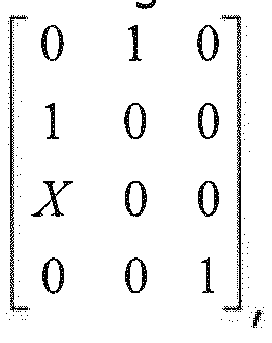

 wherein each of the precoding matrix groups includes two precoding matrices having different X value respectively.
 - The user equipment (UE) according to claim 3, wherein the codebook is set to equalize transmission power of multiple antennas.
- A method for controlling a base station (BS) to receive uplink signals of a user equipment (UE), the method comprising:receiving signals having been transmitted via four antennas (1405) and three layers from the user equipment (UE); andprocessing the received signals using a specific precoding matrix selected from a codebook,wherein the codebook consists of precoding matrix groups of


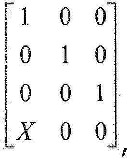


 wherein each of the precoding matrix groups includes two precoding matrices having different X value respectively.
 - A base station (BS) for receiving uplink signals of a user equipment, UE, comprising:an antenna for transmitting and receiving signals; wherein received signals have been transmitted via four antennas and three layers from the UE; 30 a memory (12) for storing a codebook anda processor (11) connected to the antenna and the memory so as to process the received signals, wherein the processor is configured to process the received signals using a specific precoding matrix selected from the codebook stored in the memory,wherein the codebook consists of precoding matrix groups of
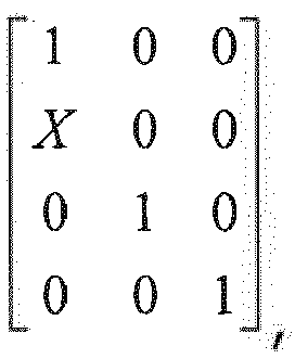


 wherein each of the precoding matrix groups includes two precoding matrices having different X value respectively.
Applications Claiming Priority (10)
| Application Number | Priority Date | Filing Date | Title |
|---|---|---|---|
| US16893109P | 2009-04-13 | 2009-04-13 | |
| US18166609P | 2009-05-28 | 2009-05-28 | |
| US18306509P | 2009-06-01 | 2009-06-01 | |
| US18431309P | 2009-06-05 | 2009-06-05 | |
| US18483009P | 2009-06-07 | 2009-06-07 | |
| US18519809P | 2009-06-09 | 2009-06-09 | |
| US18638609P | 2009-06-12 | 2009-06-12 | |
| US21939609P | 2009-06-23 | 2009-06-23 | |
| KR1020100031369A KR101670744B1 (en) | 2009-04-13 | 2010-04-06 | Uplink Signal Transmission and Reception Using the Optimized Rank 3 Codebook |
| PCT/KR2010/002261 WO2010120089A2 (en) | 2009-04-13 | 2010-04-13 | Uplink signal transmission and reception using optimized rank 3 codebook |
Publications (3)
| Publication Number | Publication Date |
|---|---|
| EP2420006A2 EP2420006A2 (en) | 2012-02-22 |
| EP2420006A4 EP2420006A4 (en) | 2012-10-10 |
| EP2420006B1 true EP2420006B1 (en) | 2018-05-30 |
Family
ID=43133036
Family Applications (1)
| Application Number | Title | Priority Date | Filing Date |
|---|---|---|---|
| EP10764628.3A Active EP2420006B1 (en) | 2009-04-13 | 2010-04-13 | Uplink signal transmission and reception using optimized rank 3 codebook |
Country Status (9)
| Country | Link |
|---|---|
| US (4) | US9007885B2 (en) |
| EP (1) | EP2420006B1 (en) |
| JP (1) | JP5587976B2 (en) |
| KR (1) | KR101670744B1 (en) |
| CN (1) | CN102362440B (en) |
| CA (1) | CA2755399C (en) |
| MX (1) | MX2011009121A (en) |
| RU (1) | RU2476995C1 (en) |
| WO (1) | WO2010120089A2 (en) |
Families Citing this family (14)
| Publication number | Priority date | Publication date | Assignee | Title |
|---|---|---|---|---|
| KR101670744B1 (en) | 2009-04-13 | 2016-11-09 | 엘지전자 주식회사 | Uplink Signal Transmission and Reception Using the Optimized Rank 3 Codebook |
| WO2010124445A1 (en) * | 2009-04-27 | 2010-11-04 | 华为技术有限公司 | A codebook, codebook generation method, uplink transmitting method and equipment based on codebook |
| KR20100136888A (en) * | 2009-06-19 | 2010-12-29 | 삼성전자주식회사 | A method for communication using codebook in mimo systems and apparatus thereof |
| US8493836B2 (en) * | 2009-06-26 | 2013-07-23 | Lg Electronics Inc. | Method and apparatus for transmitting uplink signals using optimized rank 3 codebook |
| CN102984102B (en) * | 2011-09-02 | 2016-09-07 | 华为技术有限公司 | Upstream data transmission, uplink data processing method, terminal and base station |
| KR20130134873A (en) | 2012-05-31 | 2013-12-10 | 삼성전자주식회사 | Method and apparatus for transmitting in wireless communication system |
| KR101399794B1 (en) * | 2012-10-23 | 2014-05-27 | 고려대학교 산학협력단 | Limited Feedback Method and Apparatus for Two-Way Wireless Relaying Channels with Physical Networking Coding |
| KR102184075B1 (en) * | 2013-08-07 | 2020-11-27 | 엘지전자 주식회사 | Method and apparatus for transforming data symbol for interference avoidance |
| US20160365993A1 (en) * | 2015-02-02 | 2016-12-15 | Telefonaktiebolaget Lm Ericsson (Publ) | Codeword-to-layer mapping for mimo transmissions |
| WO2016163605A1 (en) * | 2015-04-09 | 2016-10-13 | 엘지전자 주식회사 | Device for transmitting data in wireless communication system |
| US11769131B2 (en) | 2017-02-02 | 2023-09-26 | Thomas Edward Griffith | Financial processing and data management system and method |
| WO2019013058A1 (en) * | 2017-07-12 | 2019-01-17 | パナソニック インテレクチュアル プロパティ コーポレーション オブ アメリカ | Transmission device and transmission method |
| US11863259B2 (en) * | 2021-10-22 | 2024-01-02 | Lenovo (Singapore) Pte. Ltd. | Determining a precoder for wireless communications |
| US11616611B1 (en) | 2021-10-22 | 2023-03-28 | Lenovo (Singapore) Pte. Ltd. | Precoding wireless communications |
Family Cites Families (27)
| Publication number | Priority date | Publication date | Assignee | Title |
|---|---|---|---|---|
| US7593357B2 (en) | 2002-03-28 | 2009-09-22 | Interdigital Technology Corporation | Transmit processing using receiver functions |
| RU2359413C2 (en) * | 2002-10-25 | 2009-06-20 | Квэлкомм Инкорпорейтед | Detection and demodulation of data for wireless communication systems |
| US7257167B2 (en) * | 2003-08-19 | 2007-08-14 | The University Of Hong Kong | System and method for multi-access MIMO channels with feedback capacity constraint |
| US8107549B2 (en) * | 2005-11-30 | 2012-01-31 | Qualcomm, Incorporated | Multi-stage receiver for wireless communication |
| KR100918747B1 (en) | 2006-02-07 | 2009-09-24 | 삼성전자주식회사 | Apparatus and method for transmitting uplink signal in mobile communication system using an orthogonal frequency division multiple access scheme |
| US8165018B2 (en) * | 2006-03-17 | 2012-04-24 | Rockstar Bidco, LP | Closed-loop MIMO systems and methods |
| US8077788B2 (en) * | 2006-12-01 | 2011-12-13 | Rockstar Bidco, LP | Soft demapping for MIMO decoding |
| US8451915B2 (en) * | 2007-03-21 | 2013-05-28 | Samsung Electronics Co., Ltd. | Efficient uplink feedback in a wireless communication system |
| CN101669299B (en) * | 2007-03-22 | 2014-11-12 | 马维尔国际贸易有限公司 | Variable codebook for mimo system |
| US8184732B2 (en) * | 2007-05-01 | 2012-05-22 | Broadcom Corporation | Method and system for codebook design for pre-coding techniques |
| US8259824B2 (en) | 2007-05-23 | 2012-09-04 | Texas Instruments Incorporated | Nested precoding codebook structures for MIMO systems |
| US8014265B2 (en) * | 2007-08-15 | 2011-09-06 | Qualcomm Incorporated | Eigen-beamforming for wireless communication systems |
| KR20090030200A (en) * | 2007-09-19 | 2009-03-24 | 엘지전자 주식회사 | Data transmitting and receiving method using phase shift based precoding and transceiver supporting the same |
| TWI514805B (en) * | 2008-07-02 | 2015-12-21 | Interdigital Patent Holdings | Method and apparatus for measuring and reporting a rank and a precoding matrix for multiple-input multiple-output communication |
| KR101638900B1 (en) * | 2008-08-05 | 2016-07-12 | 엘지전자 주식회사 | Method of transmitting control information information of downlink multi carriers in a wireless communication system |
| US9001802B2 (en) * | 2008-08-11 | 2015-04-07 | Lg Electronics Inc. | Method and apparatus for transmitting uplink signals using multi-antenna |
| KR101549021B1 (en) * | 2008-08-20 | 2015-09-01 | 엘지전자 주식회사 | Precoding method for reduced uplink papr and appratus therefor |
| KR101707680B1 (en) * | 2008-12-21 | 2017-02-17 | 엘지전자 주식회사 | Apparatus and method of transmitting information in wireless communication system |
| CN102217206B (en) * | 2009-01-05 | 2014-10-08 | 马维尔国际贸易有限公司 | Precoding codebooks for mimo communication systems |
| KR101644433B1 (en) * | 2009-02-13 | 2016-08-01 | 엘지전자 주식회사 | Uplink Precoding Method In 4 Tx System |
| KR101068741B1 (en) * | 2009-02-13 | 2011-09-28 | 엘지전자 주식회사 | Method and device for data transmission in multi-antenna system |
| US8451932B2 (en) * | 2009-02-23 | 2013-05-28 | Texas Instruments Incorporated | Precoding codebook design for single user MIMO |
| US8301177B2 (en) * | 2009-03-03 | 2012-10-30 | Intel Corporation | Efficient paging operation for femtocell deployment |
| US20100232384A1 (en) * | 2009-03-13 | 2010-09-16 | Qualcomm Incorporated | Channel estimation based upon user specific and common reference signals |
| KR101670744B1 (en) | 2009-04-13 | 2016-11-09 | 엘지전자 주식회사 | Uplink Signal Transmission and Reception Using the Optimized Rank 3 Codebook |
| KR20110111855A (en) * | 2010-04-05 | 2011-10-12 | 주식회사 팬택 | Channel information feedback apparatus, method thereof and cell apparatus using the same |
| KR20110111962A (en) * | 2010-04-06 | 2011-10-12 | 주식회사 팬택 | Transmitter, receiver, transmitting method and receiving method in wireless communication system, amd recording medium |
-
2010
- 2010-04-06 KR KR1020100031369A patent/KR101670744B1/en active IP Right Grant
- 2010-04-13 MX MX2011009121A patent/MX2011009121A/en active IP Right Grant
- 2010-04-13 JP JP2012504630A patent/JP5587976B2/en active Active
- 2010-04-13 RU RU2011146008/07A patent/RU2476995C1/en active
- 2010-04-13 CN CN201080013166.7A patent/CN102362440B/en not_active Expired - Fee Related
- 2010-04-13 CA CA2755399A patent/CA2755399C/en active Active
- 2010-04-13 US US13/254,161 patent/US9007885B2/en active Active
- 2010-04-13 WO PCT/KR2010/002261 patent/WO2010120089A2/en active Application Filing
- 2010-04-13 EP EP10764628.3A patent/EP2420006B1/en active Active
-
2015
- 2015-03-12 US US14/645,834 patent/US9154343B2/en active Active
- 2015-08-26 US US14/836,433 patent/US9294175B2/en not_active Expired - Fee Related
-
2016
- 2016-02-11 US US15/041,849 patent/US9596015B2/en active Active
Non-Patent Citations (1)
| Title |
|---|
| None * |
Also Published As
| Publication number | Publication date |
|---|---|
| CN102362440B (en) | 2016-08-03 |
| KR20100113453A (en) | 2010-10-21 |
| CA2755399A1 (en) | 2010-10-21 |
| US20160164585A1 (en) | 2016-06-09 |
| JP2012523744A (en) | 2012-10-04 |
| EP2420006A2 (en) | 2012-02-22 |
| EP2420006A4 (en) | 2012-10-10 |
| MX2011009121A (en) | 2011-09-26 |
| KR101670744B1 (en) | 2016-11-09 |
| US20150188735A1 (en) | 2015-07-02 |
| US20150365149A1 (en) | 2015-12-17 |
| US9294175B2 (en) | 2016-03-22 |
| US9596015B2 (en) | 2017-03-14 |
| CA2755399C (en) | 2015-06-23 |
| CN102362440A (en) | 2012-02-22 |
| US20120170516A1 (en) | 2012-07-05 |
| WO2010120089A2 (en) | 2010-10-21 |
| RU2476995C1 (en) | 2013-02-27 |
| WO2010120089A3 (en) | 2011-01-20 |
| US9154343B2 (en) | 2015-10-06 |
| JP5587976B2 (en) | 2014-09-10 |
| US9007885B2 (en) | 2015-04-14 |
Similar Documents
| Publication | Publication Date | Title |
|---|---|---|
| EP2420006B1 (en) | Uplink signal transmission and reception using optimized rank 3 codebook | |
| US10236957B2 (en) | Method and apparatus for transmitting uplink signals using multi-antenna | |
| US8493836B2 (en) | Method and apparatus for transmitting uplink signals using optimized rank 3 codebook | |
| JP6196268B2 (en) | UPLINK SIGNAL TRANSFER METHOD AND DEVICE USING MULTIPLE ANTENNA | |
| KR20110107830A (en) | Multiple-antenna signal processing system and method | |
| EP2611044B1 (en) | Adaptive transmit beamforming | |
| Li et al. | A multi-user quasi-orthogonal space-time-frequency block coding scheme based beamforming |
Legal Events
| Date | Code | Title | Description |
|---|---|---|---|
| PUAI | Public reference made under article 153(3) epc to a published international application that has entered the european phase |
Free format text: ORIGINAL CODE: 0009012 |
|
| 17P | Request for examination filed |
Effective date: 20110829 |
|
| AK | Designated contracting states |
Kind code of ref document: A2 Designated state(s): AT BE BG CH CY CZ DE DK EE ES FI FR GB GR HR HU IE IS IT LI LT LU LV MC MK MT NL NO PL PT RO SE SI SK SM TR |
|
| DAX | Request for extension of the european patent (deleted) | ||
| A4 | Supplementary search report drawn up and despatched |
Effective date: 20120911 |
|
| RIC1 | Information provided on ipc code assigned before grant |
Ipc: H04L 25/03 20060101ALI20120905BHEP Ipc: H04B 7/06 20060101ALI20120905BHEP Ipc: H04B 7/04 20060101AFI20120905BHEP |
|
| STAA | Information on the status of an ep patent application or granted ep patent |
Free format text: STATUS: EXAMINATION IS IN PROGRESS |
|
| 17Q | First examination report despatched |
Effective date: 20170102 |
|
| GRAP | Despatch of communication of intention to grant a patent |
Free format text: ORIGINAL CODE: EPIDOSNIGR1 |
|
| STAA | Information on the status of an ep patent application or granted ep patent |
Free format text: STATUS: GRANT OF PATENT IS INTENDED |
|
| INTG | Intention to grant announced |
Effective date: 20171222 |
|
| GRAS | Grant fee paid |
Free format text: ORIGINAL CODE: EPIDOSNIGR3 |
|
| GRAA | (expected) grant |
Free format text: ORIGINAL CODE: 0009210 |
|
| STAA | Information on the status of an ep patent application or granted ep patent |
Free format text: STATUS: THE PATENT HAS BEEN GRANTED |
|
| AK | Designated contracting states |
Kind code of ref document: B1 Designated state(s): AT BE BG CH CY CZ DE DK EE ES FI FR GB GR HR HU IE IS IT LI LT LU LV MC MK MT NL NO PL PT RO SE SI SK SM TR |
|
| REG | Reference to a national code |
Ref country code: GB Ref legal event code: FG4D |
|
| REG | Reference to a national code |
Ref country code: CH Ref legal event code: EP |
|
| REG | Reference to a national code |
Ref country code: AT Ref legal event code: REF Ref document number: 1004669 Country of ref document: AT Kind code of ref document: T Effective date: 20180615 |
|
| REG | Reference to a national code |
Ref country code: IE Ref legal event code: FG4D |
|
| REG | Reference to a national code |
Ref country code: DE Ref legal event code: R096 Ref document number: 602010050965 Country of ref document: DE |
|
| REG | Reference to a national code |
Ref country code: NL Ref legal event code: FP |
|
| REG | Reference to a national code |
Ref country code: LT Ref legal event code: MG4D |
|
| PG25 | Lapsed in a contracting state [announced via postgrant information from national office to epo] |
Ref country code: FI Free format text: LAPSE BECAUSE OF FAILURE TO SUBMIT A TRANSLATION OF THE DESCRIPTION OR TO PAY THE FEE WITHIN THE PRESCRIBED TIME-LIMIT Effective date: 20180530 Ref country code: BG Free format text: LAPSE BECAUSE OF FAILURE TO SUBMIT A TRANSLATION OF THE DESCRIPTION OR TO PAY THE FEE WITHIN THE PRESCRIBED TIME-LIMIT Effective date: 20180830 Ref country code: NO Free format text: LAPSE BECAUSE OF FAILURE TO SUBMIT A TRANSLATION OF THE DESCRIPTION OR TO PAY THE FEE WITHIN THE PRESCRIBED TIME-LIMIT Effective date: 20180830 Ref country code: SE Free format text: LAPSE BECAUSE OF FAILURE TO SUBMIT A TRANSLATION OF THE DESCRIPTION OR TO PAY THE FEE WITHIN THE PRESCRIBED TIME-LIMIT Effective date: 20180530 Ref country code: ES Free format text: LAPSE BECAUSE OF FAILURE TO SUBMIT A TRANSLATION OF THE DESCRIPTION OR TO PAY THE FEE WITHIN THE PRESCRIBED TIME-LIMIT Effective date: 20180530 Ref country code: LT Free format text: LAPSE BECAUSE OF FAILURE TO SUBMIT A TRANSLATION OF THE DESCRIPTION OR TO PAY THE FEE WITHIN THE PRESCRIBED TIME-LIMIT Effective date: 20180530 Ref country code: CY Free format text: LAPSE BECAUSE OF FAILURE TO SUBMIT A TRANSLATION OF THE DESCRIPTION OR TO PAY THE FEE WITHIN THE PRESCRIBED TIME-LIMIT Effective date: 20180530 |
|
| PG25 | Lapsed in a contracting state [announced via postgrant information from national office to epo] |
Ref country code: LV Free format text: LAPSE BECAUSE OF FAILURE TO SUBMIT A TRANSLATION OF THE DESCRIPTION OR TO PAY THE FEE WITHIN THE PRESCRIBED TIME-LIMIT Effective date: 20180530 Ref country code: HR Free format text: LAPSE BECAUSE OF FAILURE TO SUBMIT A TRANSLATION OF THE DESCRIPTION OR TO PAY THE FEE WITHIN THE PRESCRIBED TIME-LIMIT Effective date: 20180530 Ref country code: GR Free format text: LAPSE BECAUSE OF FAILURE TO SUBMIT A TRANSLATION OF THE DESCRIPTION OR TO PAY THE FEE WITHIN THE PRESCRIBED TIME-LIMIT Effective date: 20180831 |
|
| REG | Reference to a national code |
Ref country code: AT Ref legal event code: MK05 Ref document number: 1004669 Country of ref document: AT Kind code of ref document: T Effective date: 20180530 |
|
| PG25 | Lapsed in a contracting state [announced via postgrant information from national office to epo] |
Ref country code: EE Free format text: LAPSE BECAUSE OF FAILURE TO SUBMIT A TRANSLATION OF THE DESCRIPTION OR TO PAY THE FEE WITHIN THE PRESCRIBED TIME-LIMIT Effective date: 20180530 Ref country code: DK Free format text: LAPSE BECAUSE OF FAILURE TO SUBMIT A TRANSLATION OF THE DESCRIPTION OR TO PAY THE FEE WITHIN THE PRESCRIBED TIME-LIMIT Effective date: 20180530 Ref country code: AT Free format text: LAPSE BECAUSE OF FAILURE TO SUBMIT A TRANSLATION OF THE DESCRIPTION OR TO PAY THE FEE WITHIN THE PRESCRIBED TIME-LIMIT Effective date: 20180530 Ref country code: CZ Free format text: LAPSE BECAUSE OF FAILURE TO SUBMIT A TRANSLATION OF THE DESCRIPTION OR TO PAY THE FEE WITHIN THE PRESCRIBED TIME-LIMIT Effective date: 20180530 Ref country code: RO Free format text: LAPSE BECAUSE OF FAILURE TO SUBMIT A TRANSLATION OF THE DESCRIPTION OR TO PAY THE FEE WITHIN THE PRESCRIBED TIME-LIMIT Effective date: 20180530 Ref country code: SK Free format text: LAPSE BECAUSE OF FAILURE TO SUBMIT A TRANSLATION OF THE DESCRIPTION OR TO PAY THE FEE WITHIN THE PRESCRIBED TIME-LIMIT Effective date: 20180530 Ref country code: PL Free format text: LAPSE BECAUSE OF FAILURE TO SUBMIT A TRANSLATION OF THE DESCRIPTION OR TO PAY THE FEE WITHIN THE PRESCRIBED TIME-LIMIT Effective date: 20180530 |
|
| PG25 | Lapsed in a contracting state [announced via postgrant information from national office to epo] |
Ref country code: SM Free format text: LAPSE BECAUSE OF FAILURE TO SUBMIT A TRANSLATION OF THE DESCRIPTION OR TO PAY THE FEE WITHIN THE PRESCRIBED TIME-LIMIT Effective date: 20180530 Ref country code: IT Free format text: LAPSE BECAUSE OF FAILURE TO SUBMIT A TRANSLATION OF THE DESCRIPTION OR TO PAY THE FEE WITHIN THE PRESCRIBED TIME-LIMIT Effective date: 20180530 |
|
| REG | Reference to a national code |
Ref country code: DE Ref legal event code: R097 Ref document number: 602010050965 Country of ref document: DE |
|
| PLBE | No opposition filed within time limit |
Free format text: ORIGINAL CODE: 0009261 |
|
| STAA | Information on the status of an ep patent application or granted ep patent |
Free format text: STATUS: NO OPPOSITION FILED WITHIN TIME LIMIT |
|
| 26N | No opposition filed |
Effective date: 20190301 |
|
| PG25 | Lapsed in a contracting state [announced via postgrant information from national office to epo] |
Ref country code: SI Free format text: LAPSE BECAUSE OF FAILURE TO SUBMIT A TRANSLATION OF THE DESCRIPTION OR TO PAY THE FEE WITHIN THE PRESCRIBED TIME-LIMIT Effective date: 20180530 |
|
| REG | Reference to a national code |
Ref country code: CH Ref legal event code: PL |
|
| REG | Reference to a national code |
Ref country code: BE Ref legal event code: MM Effective date: 20190430 |
|
| PG25 | Lapsed in a contracting state [announced via postgrant information from national office to epo] |
Ref country code: LU Free format text: LAPSE BECAUSE OF NON-PAYMENT OF DUE FEES Effective date: 20190413 Ref country code: MC Free format text: LAPSE BECAUSE OF FAILURE TO SUBMIT A TRANSLATION OF THE DESCRIPTION OR TO PAY THE FEE WITHIN THE PRESCRIBED TIME-LIMIT Effective date: 20180530 |
|
| PG25 | Lapsed in a contracting state [announced via postgrant information from national office to epo] |
Ref country code: LI Free format text: LAPSE BECAUSE OF NON-PAYMENT OF DUE FEES Effective date: 20190430 Ref country code: CH Free format text: LAPSE BECAUSE OF NON-PAYMENT OF DUE FEES Effective date: 20190430 |
|
| PG25 | Lapsed in a contracting state [announced via postgrant information from national office to epo] |
Ref country code: BE Free format text: LAPSE BECAUSE OF NON-PAYMENT OF DUE FEES Effective date: 20190430 |
|
| PG25 | Lapsed in a contracting state [announced via postgrant information from national office to epo] |
Ref country code: TR Free format text: LAPSE BECAUSE OF FAILURE TO SUBMIT A TRANSLATION OF THE DESCRIPTION OR TO PAY THE FEE WITHIN THE PRESCRIBED TIME-LIMIT Effective date: 20180530 |
|
| PG25 | Lapsed in a contracting state [announced via postgrant information from national office to epo] |
Ref country code: IE Free format text: LAPSE BECAUSE OF NON-PAYMENT OF DUE FEES Effective date: 20190413 |
|
| PG25 | Lapsed in a contracting state [announced via postgrant information from national office to epo] |
Ref country code: PT Free format text: LAPSE BECAUSE OF FAILURE TO SUBMIT A TRANSLATION OF THE DESCRIPTION OR TO PAY THE FEE WITHIN THE PRESCRIBED TIME-LIMIT Effective date: 20181001 |
|
| PG25 | Lapsed in a contracting state [announced via postgrant information from national office to epo] |
Ref country code: IS Free format text: LAPSE BECAUSE OF FAILURE TO SUBMIT A TRANSLATION OF THE DESCRIPTION OR TO PAY THE FEE WITHIN THE PRESCRIBED TIME-LIMIT Effective date: 20180930 |
|
| PG25 | Lapsed in a contracting state [announced via postgrant information from national office to epo] |
Ref country code: HU Free format text: LAPSE BECAUSE OF FAILURE TO SUBMIT A TRANSLATION OF THE DESCRIPTION OR TO PAY THE FEE WITHIN THE PRESCRIBED TIME-LIMIT; INVALID AB INITIO Effective date: 20100413 Ref country code: MT Free format text: LAPSE BECAUSE OF FAILURE TO SUBMIT A TRANSLATION OF THE DESCRIPTION OR TO PAY THE FEE WITHIN THE PRESCRIBED TIME-LIMIT Effective date: 20180530 |
|
| PG25 | Lapsed in a contracting state [announced via postgrant information from national office to epo] |
Ref country code: MK Free format text: LAPSE BECAUSE OF FAILURE TO SUBMIT A TRANSLATION OF THE DESCRIPTION OR TO PAY THE FEE WITHIN THE PRESCRIBED TIME-LIMIT Effective date: 20180530 |
|
| PGFP | Annual fee paid to national office [announced via postgrant information from national office to epo] |
Ref country code: FR Payment date: 20230306 Year of fee payment: 14 |
|
| PGFP | Annual fee paid to national office [announced via postgrant information from national office to epo] |
Ref country code: GB Payment date: 20230306 Year of fee payment: 14 |
|
| P01 | Opt-out of the competence of the unified patent court (upc) registered |
Effective date: 20230523 |
|
| PGFP | Annual fee paid to national office [announced via postgrant information from national office to epo] |
Ref country code: NL Payment date: 20230307 Year of fee payment: 14 |
|
| PGFP | Annual fee paid to national office [announced via postgrant information from national office to epo] |
Ref country code: DE Payment date: 20230306 Year of fee payment: 14 |
|
| PGFP | Annual fee paid to national office [announced via postgrant information from national office to epo] |
Ref country code: NL Payment date: 20240306 Year of fee payment: 15 |