EP2418863A2 - Display apparatus - Google Patents
Display apparatus Download PDFInfo
- Publication number
- EP2418863A2 EP2418863A2 EP20110174909 EP11174909A EP2418863A2 EP 2418863 A2 EP2418863 A2 EP 2418863A2 EP 20110174909 EP20110174909 EP 20110174909 EP 11174909 A EP11174909 A EP 11174909A EP 2418863 A2 EP2418863 A2 EP 2418863A2
- Authority
- EP
- European Patent Office
- Prior art keywords
- image
- light
- duty control
- control signals
- emitting module
- Prior art date
- Legal status (The legal status is an assumption and is not a legal conclusion. Google has not performed a legal analysis and makes no representation as to the accuracy of the status listed.)
- Granted
Links
Images



Classifications
-
- H—ELECTRICITY
- H05—ELECTRIC TECHNIQUES NOT OTHERWISE PROVIDED FOR
- H05B—ELECTRIC HEATING; ELECTRIC LIGHT SOURCES NOT OTHERWISE PROVIDED FOR; CIRCUIT ARRANGEMENTS FOR ELECTRIC LIGHT SOURCES, IN GENERAL
- H05B45/00—Circuit arrangements for operating light-emitting diodes [LED]
- H05B45/10—Controlling the intensity of the light
-
- H—ELECTRICITY
- H04—ELECTRIC COMMUNICATION TECHNIQUE
- H04N—PICTORIAL COMMUNICATION, e.g. TELEVISION
- H04N13/00—Stereoscopic video systems; Multi-view video systems; Details thereof
- H04N13/30—Image reproducers
- H04N13/356—Image reproducers having separate monoscopic and stereoscopic modes
-
- G—PHYSICS
- G09—EDUCATION; CRYPTOGRAPHY; DISPLAY; ADVERTISING; SEALS
- G09G—ARRANGEMENTS OR CIRCUITS FOR CONTROL OF INDICATING DEVICES USING STATIC MEANS TO PRESENT VARIABLE INFORMATION
- G09G3/00—Control arrangements or circuits, of interest only in connection with visual indicators other than cathode-ray tubes
- G09G3/20—Control arrangements or circuits, of interest only in connection with visual indicators other than cathode-ray tubes for presentation of an assembly of a number of characters, e.g. a page, by composing the assembly by combination of individual elements arranged in a matrix no fixed position being assigned to or needed to be assigned to the individual characters or partial characters
- G09G3/34—Control arrangements or circuits, of interest only in connection with visual indicators other than cathode-ray tubes for presentation of an assembly of a number of characters, e.g. a page, by composing the assembly by combination of individual elements arranged in a matrix no fixed position being assigned to or needed to be assigned to the individual characters or partial characters by control of light from an independent source
- G09G3/3406—Control of illumination source
-
- H—ELECTRICITY
- H04—ELECTRIC COMMUNICATION TECHNIQUE
- H04N—PICTORIAL COMMUNICATION, e.g. TELEVISION
- H04N13/00—Stereoscopic video systems; Multi-view video systems; Details thereof
- H04N13/30—Image reproducers
- H04N13/332—Displays for viewing with the aid of special glasses or head-mounted displays [HMD]
- H04N13/341—Displays for viewing with the aid of special glasses or head-mounted displays [HMD] using temporal multiplexing
-
- H—ELECTRICITY
- H05—ELECTRIC TECHNIQUES NOT OTHERWISE PROVIDED FOR
- H05B—ELECTRIC HEATING; ELECTRIC LIGHT SOURCES NOT OTHERWISE PROVIDED FOR; CIRCUIT ARRANGEMENTS FOR ELECTRIC LIGHT SOURCES, IN GENERAL
- H05B45/00—Circuit arrangements for operating light-emitting diodes [LED]
- H05B45/30—Driver circuits
- H05B45/37—Converter circuits
-
- G—PHYSICS
- G09—EDUCATION; CRYPTOGRAPHY; DISPLAY; ADVERTISING; SEALS
- G09G—ARRANGEMENTS OR CIRCUITS FOR CONTROL OF INDICATING DEVICES USING STATIC MEANS TO PRESENT VARIABLE INFORMATION
- G09G2360/00—Aspects of the architecture of display systems
- G09G2360/14—Detecting light within display terminals, e.g. using a single or a plurality of photosensors
- G09G2360/145—Detecting light within display terminals, e.g. using a single or a plurality of photosensors the light originating from the display screen
Definitions
- Exemplary embodiments of the present invention relate to a display apparatus. More particularly, exemplary embodiments of the present invention relate to a display apparatus having an enhanced display quality.
- a display apparatus displays a two-dimensional (“2D”) image.
- 2D two-dimensional
- 3D three-dimensional
- a 3D image may be perceived by an observer when the observer watches two different 2D images through a left eye and a right eye, respectively, and the two different 2D images are combined in the observer's brain.
- a 3D image display apparatus typically displays a 3D image using a binocular parallax through two eyes of the observer. That is, images of an object are viewed at different angles by each of the two eyes and the images viewed at different angles are inputted to the observer's brain since the two eyes of the observer are spaced apart from each other.
- Conventional 3D image display apparatus using the binocular parallax may be divided into a stereoscopic type (with glasses) display apparatus and an autostereoscopic type (without glasses) display apparatus.
- the stereoscopic type display apparatus may be divided into an anaglyph type display apparatus and a shutter glasses type display apparatus, for example.
- anaglyph type display apparatus a pair of glasses having a blue lens and a red lens is typically used.
- the shutter glasses type display apparatus a left-eye image and a right-eye image are temporally divided to be displayed thereon in a period, and a pair of glasses, in which a left-eye shutter and a right-eye shutter are closed and opened in a synchronized manner with the period, is typically used.
- a 3D liquid crystal display (“LCD”) apparatus is generally driven in a progressive scan method, time points at which a line data is applied to a plurality of horizontal lines of the LCD apparatus are different from each other, and liquid crystal responses at a same time point are different from each other.
- a substantial amount of crosstalk may be generated due to different gradations between the left-eye image and the right-eye image and different display timings between the left-eye image and the right-eye image when driven by the progressive scan method.
- the crosstalk may substantially decrease a display quality of a 3D image.
- direct-illumination type light emitting diodes LEDs
- edge type LEDs may be used to prevent the crosstalk.
- a serial communication is typically employed to drive a light source such as the direct-illumination type LEDs and edge type LEDs.
- manufacturing costs of the LCD apparatus may substantially increase when direct-illumination type LEDs and edge type LEDs are used.
- Exemplary embodiments of the present invention provide a display apparatus which has an enhanced display quality to be manufactured in low manufacturing costs.
- a display apparatus includes a display panel and a light source module.
- the display panel displays a first image during an N-th frame included in a first interval and an (N+1)-th frame included a second interval, where N is a natural number.
- the light source module includes a first light-emitting module, a second light-emitting module and a light source driving part.
- the first light-emitting module includes first to k-th top light source blocks disposed adjacent to a first edge of a light guide plate, where k is a natural number.
- the second light-emitting module includes first to m-th bottom light source blocks disposed adjacent to a second edge of the light guide plate, where m is a natural number, and the second edge is disposed opposite to the first edge.
- the light source driving part generates first to k-th top duty control signals and first to m-th bottom duty control signals based on the first image, selectively generates first to k-th top driving signals and first to m-th bottom driving signals using the first to k-th duty control signals and the first to m-th duty control signals, respectively, based on a three-dimensional image enable signal, and drives the first light-emitting module during the first interval and the second light-emitting module during the second interval, where the first to k-th top duty control signals correspond to the first to k-th top light source blocks, and the first to m-th bottom duty control signals correspond to the first to m-th bottom light source blocks, and where the first to k-th top driving signals drive the first light-emitting module,
- the display apparatus may further include a shutter glasses including a first shutter and a second shutter.
- the display panel may display a second image during an (N+2)-th frame included in the first interval and an (N+3)-th frame included in the second interval.
- the first shutter may be opened and the second shutter may be closed in correspondence with the N-th frame and the (N+1)-th frame.
- the first shutter may be closed and the second shutter may be opened in correspondence with the (N+2)-th frame and the (N+3)-th frame.
- the shutter glasses may open and close the first shutter after a preset time in response to a vertical start signal of a left-eye image of the first image, and the shutter glasses may open and close the second shutter after the preset time in response to a vertical start signal of a right-eye image of the second image.
- the light source driving part may include a dimming level determining part and a duty control signal generating part.
- the dimming level determining part determines the first to k-th top duty ratios and first to m-th bottom duty ratios using the first image and the second image.
- the duty control signal generating part generates the first to k-th top duty control signals and the first to m-th bottom duty control signals using the first to k-th top duty ratios and the first to m-th bottom duty ratios.
- the dimming control part may include an image analyzing part and a dimming level determining part.
- the image analyzing part obtains a representative luminance value by analyzing the first image and the second image corresponding to the first to k-th top light source blocks and the first to m-th bottom light source blocks to.
- the dimming level determining part determines the first to k-th top duty ratios and the first to m-th bottom duty ratios using the representative luminance value, where the first to k-th top duty ratios control a brightness of the first to k-th top light source blocks, and the first to m-th bottom duty ratios control a brightness of the first to m-th bottom light source blocks.
- the duty control signal generating part may include a first converting part and a second converting part.
- the first converting part generates the first to k-th top driving signals using the first to k-th top duty control signals when the three-dimensional image enable signal has a low level, and generates the first to k-th top driving signals using the first to k-th top duty control signals during a first interval when the three-dimensional image enable signal has a high level.
- the second converting part generates the first to m-th bottom driving signals using the first to m-th bottom duty control signals when the three-dimensional image enable signal has a low level, and generates the first to m-th bottom driving signals using the first to m-th bottom duty control signals during a second interval when the three-dimensional image enable signal has a high level.
- the first converting part may include a first switching part and a first driving part.
- the first switching part transmits the first to k-th top duty control signals in response to a first enable signal, and blocks the first to k-th top duty control signals in response to a second enable signal, where the first enable signal has a high level in correspondence with the first interval, and the second enable signal has a high level in correspondence with the second interval.
- the first driving part generates the first to k-th top driving signals using the first to k-th top duty control signals provided from the first switching part, and drives the first light-emitting module.
- the second converting part may include a second switching part and a second driving part.
- the second switching part transmits the first to m-th bottom duty control signals in response to the second enable signal, and blocks the first to m-th bottom duty control signals in response to the first enable signal, where the first enable signal has a high level in correspondence with the first interval, and the second enable signal has a high level in correspondence with the second interval.
- the second driving part generates the first to m-th bottom driving signals using the first to m-th bottom duty control signals provided from the second switching part, and drives the second light-emitting module.
- the first switching part may include first to k-th switches
- the second switching part may include first to m-th switches.
- each of the first driving part and the second driving part may boost the first to k-th top duty control signals and the first to m-th bottom duty control signals, respectively, in response to the three-dimensional image enable signal.
- the first enable signal may be synchronized with a first image data of the first image after a preset time in response to a vertical start signal of a left-eye image included in the first image
- the second enable signal may be synchronized with a first image data of the second image after the preset time in response to a vertical start signal of a right-eye image included in the second image.
- the first image may include a left-eye image and a black image
- the second image may include a right-eye image and the black image.
- the left-eye image included in the first image may be sequentially displayed on first to k-th display blocks of the display panel during the N-th frame and the (N+1)-th frame
- the right-eye image included in the second image may be sequentially displayed on the first to k-th display blocks of the display panel during the (N+2)-th frame and the (N+3)-th frame.
- a first light-emitting module and a second light-emitting module using edge type light-emitting diodes (“LEDs”) are driven using first to k-th top duty control signals parallelly applied to a display apparatus, so that the display apparatus may be driven in a dimming driving mode.
- the crosstalk generated therein is substantially decreased, the display quality of the display apparatus is substantially enhanced, and the manufacturing cost of the display apparatus is substantially reduced.
- FIG 1 is a block diagram illustrating an exemplary embodiment of a display apparatus according to the present invention.
- FIG 2 is a block diagram illustrating an exemplary embodiment of an image converting part of FIG 1 ;
- FIG 3 is a schematic circuit diagram illustrating a first light-emitting module, a second light-emitting module and a duty control signal converting part of an exemplary embodiment of a light source module 400 in FIG 1 ;
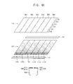
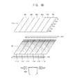
- FIGS. 4A and 4B are perspective plan views illustrating a shutter glasses, a display panel, a light-guide plate, a first light-emitting module and a second light-emitting module that are used when a three-dimensional ("3D") image is displayed on the display apparatus of FIG 1 ; and
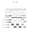
- FIGS. 5A and 5B are signal timing diagrams of signals used in an exemplary embodiment of a driving method of first and second light-emitting modules of FIG 1 and an exemplary embodiment of an image display method of a display apparatus using the driving method.
- first, second, third, etc. may be used herein to describe various elements, components, regions, layers and/or sections, these elements, components, regions, layers and/or sections should not be limited by these terms. These terms are only used to distinguish one element, component, region, layer or section from another region, layer or section. Thus, a first element, component, region, layer or section discussed below could be termed a second element, component, region, layer or section without departing from the teachings of the invention.
- FIG 1 is a block diagram illustrating an exemplary embodiment of a display apparatus according to the present invention.
- the display apparatus includes a display unit 100, an image converting part 200, a timing control part 300 and a light source module 400.
- the display apparatus may selectively display a two dimensional ("2D") image and a three-dimensional ("3D") image.
- the display apparatus includes a display panel 110.
- the display panel 100 may be a full high definition (“FHD") display panel having a high resolution, such as a resolution of 1920 X 1080, for example.
- the display unit 100 further includes a panel driving part 130 which drives the display panel 110.
- the panel driving part 130 includes a data driving part 132 and a gate driving part 134.
- the display panel 110 displays images based on a data signal outputted from the data driving part 132 and a gate signal outputted from the gate driving part 134.
- the display panel 110 may include two substrates and a liquid crystal interposed between the two substrates.
- the display panel 110 may include a plurality of pixels for displaying images.
- Each of the pixels may include a switching element electrically connected to a gate line and a data line, a liquid crystal capacitor electrically connected to the switching element and a storage capacitor electrically connected to the switching element.
- the data driving part 132 converts a digital data signal into a data voltage, which may be an analog voltage, based on a first control signal CONT1 and an image data DATA that are received from the timing control part 300, and then outputs the data voltage to data lines.
- the gate driving part 134 generates gate signals to be applied to gate lines disposed on the display panel 110 based on a second control signal CONT2 received from the timing control part 300, and sequentially outputs the gate signals to the gate lines.
- the image converting part 200 receives a first image signal from a video system (not shown) disposed at an outside.
- the first image signal may be a 2D image signal or a 3D image signal.
- the image converting part 200 divides the first image signal into a left-eye image signal and a right-eye image signal to recombine a left-eye and right-eye images, and then provides the timing control part 300 with a first output image 201a.
- the first image signal is the 2D image signal
- the image converting part 200 provides the timing control part 300 with a second output image 201b.
- the timing control part 300 receives a control signal CONT applied from an external device (not shown), generates the first control signal CONT1 for controlling a driving timing of the data driving part 132 and the second control signal CONT2 for controlling a driving timing of the gate driving part 134, and provides the data driving part 132 and the gate driving part 134 with the first control signal CONT1 and the second control signal CONT2, respectively.
- the timing control part 300 provides an image analyzing part 452 of the light source driving part 450 with a third control signal CONT3 for controlling a driving timing of the light source driving part 450 and a second image signal DS for generating driving signals of the light source driving part 450.
- the light source module 400 includes a light guide plate (“LGP") 401, a first light-emitting module 410, a second light-emitting module 430 and a light source driving part 450.
- LGP light guide plate
- the first light-emitting module 410 is disposed adjacent to a first edge of the LGP 401
- the second light-emitting module 430 is disposed adjacent to a second edge of the LGP 401.
- the first and second light-emitting modules 410 and 430 include first to k-th top light source blocks and first to m-th bottom light source blocks, respectively.
- 'k' and 'm' are natural numbers.
- each of the light source blocks may include a plurality of light-emitting diodes ("LED"s).
- the number of light source blocks of the first light-emitting module 410 may be equal to the number of light source blocks of the second light-emitting module 430.
- 'k' is equal to 'm'.
- the number of light source blocks of the first light-emitting module 410 may be different from the number of light source blocks of the second light-emitting module 430. That is, 'k' is different from ⁇ m'.
- 'k' is equal to ⁇ m,'.
- the light source driving part 450 includes a dimming control part 451 and a duty control signal converting part 457.
- the dimming control part 451 includes an image analyzing part 452, a dimming level determining part 453 and a duty control signal generating part 455.
- the image analyzing part 452 determines representative luminance values of the first to k-th top light source blocks and the first to m-th bottom light source blocks using a third control signal CONT3 and a second image signal DS, which are provided from the timing control part 300.
- the image analyzing part 452 analyzes a second image signal of a frame unit to determine a representative value of a display block DB when lights irradiated from the first to k-th light source blocks and first to m-th light source blocks are incident on the display panel 110.
- the representative luminance value of the light source blocks may be determined using a representative value of gray levels of image signal corresponding to the display block, such as a maximum value, an average value, a weighted average value and an optimum value between the maximum value or the average value, for example.
- the dimming level determining part 453 determines first to k-th top duty ratios corresponding to amounts of light emitted by the first to k-th top light source blocks and first to m-th bottom duty ratios corresponding to amounts of light emitted by the first to m-th bottom light source blocks using the representative luminance values.
- the duty control signal generating part 455 generates the first to k-th top control signals which control the amounts of light emitted by the first to k-th top light source blocks using the first to k-th top duty ratios.
- the duty control signal generating part 455 generates the first to m-th bottom control signals which control the amounts of light emitted by the first to m-th bottom light source blocks using the first to m-th bottom duty ratios.
- the duty control signal generating part 455 generates the first to k-th top duty control signals having a predetermined frequency and the first to m-th bottom duty control signals using the third control signal CONT3.
- the third control signal CONT3 may include the vertical start signal and a horizontal synchronization signal.
- the duty control signal converting part 457 converts the first to k-th top duty control signals and the first to m-th bottom duty control signals, in which a pulse width and a frequency are controlled in the duty control signal generating part 455, into first to k-th top driving signals and first to m-th bottom driving signals that are applied to the first light-emitting module 410 and the second light-emitting module 430, respectively.
- the duty control signal converting part 457 may include a converter which converts a direct current (“DC”) voltage into an alternating current (“AC”) voltage.
- FIG 2 is a block diagram illustrating an exemplary embodiment of the image converting part 200 of FIG 1 .
- the image converting part 200 includes a mode determining part 210, a dividing part 220, a scaler 230 and a black image generating part 240.
- the mode determining part 210 determines a mode of the first image signal.
- the mode determining part 210 delivers the first image signal to dividing part 220, and the first image signal is thereby processed so that a first output image 201a is provided to the timing control part 300.
- the mode determining part 210 may provide the first image signal as a second output image 201b directly to the timing control part 300.
- the dividing part 220 divides the first image signal received from the mode determining part 210 into the left-eye image signal and the right-eye image signal.
- the scaler 230 converts resolutions of the left-eye image signal and the right-eye image signal received from the dividing part 220 to correspond to a resolution of the display panel 110, and then delivers the converted left-eye and right-eye image signals to the black image generating part 240.
- the black image generating part 240 generates a black image.
- the black image generating part 240 inserts the black image between the left-eye image and the right-eye image received from the scaler 230 to generate the first output image 201a, and then outputs the first output image 201a to the timing control part 300.
- the timing control part 300 controls a display timing of the first and second output images 201a and 201b, so that each of the first and second output images 201a and 201b is displayed to correspond to the display block DB of the display panel 110.
- FIG 3 is a schematic circuit diagram illustrating a first light-emitting module 410, a second light-emitting module 430 and a duty control signal converting part 457 of an exemplary embodiment of the light source module 400 in FIG 1 .
- the duty control signal converting part 457 includes a boosting part 457a, a first converting part 457b and a second converting part 457c.
- the boosting part 457a includes an inductor L, a diode D, a switching element SW and a converter 457a1.
- the switching element SW is electrically connected to the inductor L, the diode D and the converter 457a1.
- the first light-emitting module 410 and the second light-emitting module 430 are connected to a cathode of the diode D.
- a first terminal of the inductor L and an anode of the diode D are connected to the converter 457a1 via the switching element SW.
- An output terminal of the boosting part 457a is commonly connected to anodes of light source blocks in which a plurality of light-emitting diodes is serially connected to one another.
- the converter 457a1 may convert the input voltage Vin into an output voltage Vout that is boosted.
- the input voltage Vin when an input voltage Vin is applied to the inductor L, the input voltage Vin is boosted to be converted as the output voltage Vout, and the output voltage Vout may be provided to the first light-emitting module 410 and the second light-emitting module 430.
- the input voltage Vin and the output voltage Vout may be DC voltages.
- the first converting part 457b includes a first switching part 457d1 and a first driving part 457d2.
- the second converting part 457c includes a second switching part 457e1 and a second driving part 457e2.
- the first switching part 457d1 includes a plurality of first switches SE1, and the second switching part 457e1 includes a plurality of second switches SE2.
- the first switching part 457d1 may include first to k-th switches
- the second switching part 457e1 may include first to m-th switches.
- 'k' and 'm' are natural numbers.
- a description for the first and second switching parts 457d1 and 457e1 will be described in greater detail with reference to an exemplary embodiment shown in FIG 3 in which 'k' and 'm' are equal to each other.
- the numbers of switches in the first and second switching parts 457d1 and 457e1 are not limited to the exemplary embodiment shown in FIG 3 .
- the numbers of switches in the first and second switching parts 457d1 and 457e1 may be different from each other, that is, 'k' and 'm' are not equal to each other.
- the first switching part 457d1 and the second switching part 457e1 receive the first to k-th top duty control signals PWM1 to PWMk and the first to m-th bottom duty control signals PWM1 to PWMm, respectively, from the duty control signal generating part 455 of FIG 1 .
- the first to k-th top duty control signals PWM1 to PWMk may be applied to the first switching part 457d1 and the second switching part 457e1 in parallel, as shown in FIG 3 .
- the first switching part 457d1 may further receive a first enable signal TE, and the second switching part 457e1 may further receive a second enable signal BE.
- the first switches SE1 of the first switching part 457d1 may provide the first driving part 457d2 with the first to k-th top duty control signals PWM1 to PWMk in response to the first enable signal TE.
- the second switches SE2 of the second switching part 457e1 may provide the second driving part 457e2 with the first to k-th top duty control signals PWM1 to PWMk in response to the second enable signal BE.
- the 3D image enable signal 3DE is applied to the first driving part 457d2 and the second driving part 457e2.
- the 3D image enable signal 3DE has a low value when the second image signal DS is a 2D image signal, and the 3D image enable signal 3DE has a high value when the second image signal DS is a 3D image signal.
- the first enable signal TE and the second enable signal BE may have a high value when the second image signal DS is a 2D image signal, and the first enable signal TE and the second enable signal BE may have complementary values when the second image signal DS is a 3D image signal.
- the second enable signal BE when the second image signal DS is the 3D image signal, the second enable signal BE has a low value and the first enable signal TE has a high value, or the second enable signal BE has a high value and the first enable signal TE has a low value.
- the first driving part 457d2 and the second driving part 457e2 convert the first to k-th top duty control signals PWM1 to PWMk, provided from the first switching part 457d1 and the second switching part 457e1, into the first to k-th top driving signals and the first to m-th bottom driving signals that are applied to the first light-emitting module 410 and the second light-emitting module 430, respectively.
- the first driving part 457d2 and the second driving part 457e2 may output k driving signals when 'k' and 'm' are equal to each other.
- the first light-emitting module 410 may receive the first to k-th top driving signals by the first enable signal TE having a high value, and the second light-emitting module 430 may receive the first to m-th bottom driving signals that are substantially equal to the first to k-th top driving signals by the second enable signal BE having a high value.
- the first light-emitting module 410 and the second light-emitting module 430 may perform a normal dimming driving.
- the first to k-th top duty control signals PWM1 to PWMk are complementarily provided to the first light-emitting module 410 and the second light-emitting module 430 as the first to k-th top driving signals and the first to m-th bottom driving signals.
- the display panel 110 may be driven to display a 3D image.
- FIGS. 4A and 4B are perspective plan views illustrating a shutter glasses, a display panel, a light-guide plate, a first light-emitting module and a second light-emitting module that are used when a 3D image is displayed on the display apparatus of FIG 1 .
- an exemplary embodiment of the display panel 110 may include a plurality of display blocks, e.g., a first display block DB1, a second display block DB2, a third display block DB3, a fourth display block DB4, a fifth display block DB5 and a sixth display block DB6.
- the left-eye image or the light-eye image may be sequentially displayed on the first to sixth display blocks DB1, DB2, DB3, DB4, DB5 and DB6.
- Each of the first to sixth light-emitting blocks LEB1, LEB2, LEB3, LEB4, LEB5 and LEB6 included in the light source module 400 provides lights to each of the first to sixth display blocks DB1, DB2, DB3, DB4, DB5 and DB6 of the display panel 110. That is, the first to sixth light-emitting blocks LEB1, LEB2, LEB3, LEB4, LEB5 and LEB6 may correspond to the first to sixth display blocks DB1, DB2, DB3, DB4, DB5 and DB6, respectively.
- the display blocks may be indicated as the first to k-th display blocks DB 1 to DBk.
- the first to sixth light-emitting blocks LEB 1, LEB2, LEB3, LEB4, LEB5 and LEB6 may be defined by a portion of the LGP 401 which emits lights, incident thereon from corresponding light source blocks of the first and second light-emitting modules 410 and 430, to a display panel 110.
- the first light-emitting module 410 provides the first to sixth light-emitting blocks LEB1, LEB2, LEB3, LEB4, LEB5 and LEB6 with lights based on the first to sixth top driving signals
- the second light-emitting module 430 provides the first to sixth light-emitting blocks LEB1, LEB2, LEB3, LEB4, LEB5 and LEB6 with lights based on the first to sixth bottom driving signals.
- the first light-emitting module 410 when the left-eye image is displayed on the first to sixth display blocks DB1, DB2, DB3, DB4, DB5 and DB6, the first light-emitting module 410 may be turned on and the second light-emitting module 430 may be turned off.
- the second light-emitting module 430 when the left-eye image is displayed on the first to sixth display blocks DB1, DB2, DB3, DB4, DB5 and DB6, the second light-emitting module 430 may be turned on and the first light-emitting module 410 may be turned off.
- the first light-emitting module 410 and the second light-emitting module 430 are alternately turned on and off.
- a light amount of the LGP 401 may substantially gradually decrease from a portion adjacent to the first light-emitting module 410 to a portion adjacent to the second light-emitting module 430.
- the light amount of the LGP 401 may substantially gradually increase from the portion adjacent to the first light-emitting module 410 to the portion adjacent to the second light-emitting module 430.
- the light source module 400 may further include an infrared light generating part (not shown).
- the infrared light generating part may include a plurality of infrared light sources, e.g., infrared LEDs, that generates infrared lights.
- the infrared light generating part may generate the infrared lights in response to a synchronization signal that may controls a driving of shutter glasses 600.
- the shutter glasses 600 include a left-eye lens part 610 and a right-eye lens part 620.
- the left-eye lens part 610 includes a first lens 611 and a first shutter 613
- the right-eye lens part 620 includes a second lens 621 and a second shutter 623.
- the shutter glasses 600 open the first shutter 613 and close the second shutter 623 when the left-eye image is displayed on the display panel 110
- the shutter glasses 600 open the second shutter 623 and close the first shutter 613 when the right-eye image is displayed on the display panel 110.
- an observer may view a left-eye frame image displayed on the display panel 110 during a single frame. Similarly, the observer may view a right-eye frame image displayed on the display panel 110 during a single.
- FIGS. 5A and 5B are signal timing diagrams of signals used in an exemplary embodiment of a driving method of first and second light-emitting modules of FIG 1 and an exemplary embodiment of an image display method of a display apparatus using the driving method.
- the display panel 110 may be divided into a first display area DA1, a second display area DA2, a third display area DA3, a fourth display area DA4, a fifth display area DA5 and a sixth display area DA6 based on a light amount of a corresponding portion of the LGP 401.
- the display panel 110 adjacent to the first light-emitting module 410 may be indicated as the first display area DA1
- the display panel 110 adjacent to the second light-emitting module 430 may be indicated as the sixth display area DA6.
- An area between the first and sixth display areas DA1 and DA6 may be defined as the second to fifth display areas DA2, DA3, DA4 and DA5
- First to sixth image data DD1, DD2, DD3, DD4, DD5 and DD6 may be applied to the fist to sixth display areas DA1, DA2, DA3, DA4, DA5 and DA6, respectively.
- six image data e.g., the first to sixth image data DD1, DD2, DD3, DD4, DD5 and DD6, are data provided to the first to sixth display areas DA1, DA2, DA3, DA4, DA5 and DA6 when the display panel 110 is divided into six display areas, e.g., the first to sixth display areas DA1, DA2, DA3, DA4, DA5 and DA6.
- the number of display areas is not limited thereto.
- a plurality of gate lines may be divided into P groups ( ⁇ P' is a natural number), and the image data DATA may be thereby divided into P display areas and P image data to correspond to the gate line groups.
- Each of the first to sixth image data DD1, DD2, DD3, DD4, DD5 and DD6 alternately provides a left-eye image, a black image and a right-eye image on a display area.
- a left-eye image of a single frame of the first to sixth image data DD1, DD2, DD3, DD4, DD5 and DD6 is combined with a black image of a single frame and thereby provided to the first to sixth display areas DA1, DA2, DA3, DA4, DA5 and DA6 during an N-th frame and an (N+1)-th frame ('N' is a natural number). That is, as shown in FIGS. 1 and 5B , a left-eye image L included in the image data DATA is provided to the display panel 110 during the N-th frame, and a black image B included in the image data DATA is provided to the display panel 110 during the (N+1)-th frame.
- the first to sixth image data DD1, DD2, DD3, DD4, DD5 and DD6 may be provided to the first to sixth display areas DA1, DA2, DA3, DA4, DA5 and DA6 of the display panel 110 in accordance with gate on signals sequentially generated at the gate driving part 134 of FIG 1 .
- left-eye image signals corresponding to the first to sixth image data DD1, DD2, DD3, DD4, DD5 and DD6, respectively may be sequentially shifted from the left-eye image signal corresponding to the first image data DD1 to the left-eye image signal corresponding to the sixth image data DD6.
- the display apparatus may be driven at a frequency of about 120 Hz in correspondence with a 2D image of FIG 5B , and may be driven at a frequency of about 240 Hz in correspondence with a 3D image.
- each of the first driving part 457d2 and the second driving part 457e2 may be integrated into a single driving chip in an exemplary embodiment.
- the first switching part 457d1 and the first driving part 457d2 may be integrated into a single chip
- the second switching part 457e1 and the second driving part 457e2 may be integrated into a single chip.
- an interval of the left-eye image or the right-eye image of the one frame unit may be greater than an interval of the black image in correspondence with each of the first to k-th light-emitting blocks LEB, and a phase variation may be realized.
- a luminance decrease may be effectively prevented when the 3D image is displayed thereon.
- the first enable signal TE When the first enable signal TE is in a high state, the light amount corresponding to the portion of the LGP 401 adjacent to the first light-emitting module 410 becomes large, and the light amount corresponding to the portion of the LGP 401 adjacent to the second light-emitting module 430 becomes small.
- the second light-emitting module 430 when the first enable signal TE is in the high state, the second light-emitting module 430 may be turned off.
- a first shutter signal S1 that opens the first shutter 613 is turned on during two frames in which the left-eye image and the black image are applied, and then turned off during two frames in which the right-eye image and the black image are applied.
- the two frames may correspond to a unit period of the first enable signal TE or a unit period of the second enable signal BE, as shown in FIG 5A .
- the first enable signal TE and the first shutter signal S1 may be synchronized with each other after a preset time to in response to a vertical start signal of a left-eye image signal included in the first image data DD1.
- the second enable signal BE when the second enable signal BE is in a high state, the light amount corresponding to the portion of LGP 401 adjacent to the second light-emitting module 430 becomes large, and the light amount corresponding to the portion of LGP 401 adjacent to the first light-emitting module 410 becomes small.
- the first light-emitting module 410 when the second enable signal BE is in the high state, the first light-emitting module 410 may be turned off.
- a second shutter signal S2 that opens the second shutter 623 is turned on during two frames in which the right-eye image and the black image are applied, and then turned off during two frames in which the left-eye image and the black image are applied.
- the two frames may correspond to a unit period of the first enable signal TE or a unit period of the second enable signal BE.
- the second enable signal BE and the second shutter signal S2 may be synchronized with each other after the preset time to in response to a vertical start signal of the right-eye image signal included in the first image data DD 1.
- an image data DATA is provided to the display panel 110.
- the image data DATA correspond to a 2D image during an (N-2)-th frame and an (N-1)-th frame
- the 3D image enable signal 3DE has a low value and the first enable signal TE and the second enable signal BE have a high value.
- the first converting part 457b and the second converting part 457c may output the first to k-th top duty control signals PWM1 to PWMk as the first to k-th top driving signals and the first to m-th bottom driving signals.
- the first and k-th top duty control signals PWM1 and PWMk may be substantially equal to signals of a first channel CH1 of the first driving part 457d2 and a k-th channel CHk of the first driving part 457d2, respectively.
- the first and k-th top duty control signals PWM1 and PWMk may be substantially equal to signals of a first channel CH1 of the second driving part 457e2 and a k-th channel CHk of the second driving part 457e2, respectively.
- a left image may be applied during an N-th frame and an (N+4)-th frame
- a right image may be applied during an (N+2)-th frame
- a black image may be applied during an (N+1)-th frame, an (N+3)-th frame and an (N+5)-th frame.
- the 3D image enable signal 3DE has a high value
- the first enable signal TE has a high value
- the second enable signal BE has a low value
- the first converting part 457b may output the first to k-th top duty control signals PWM1 to PWMk, while the second converting part 457c may output a signal having a low value.
- signals outputted through the first channel CH1 of the first driving part 457d2 and the k-th channel CHk of the first driving part 457d2 are the first and k-th top duty control signals PWM1 and PWMk in accordance with the N-th frame, the (N+2)-th frame and the (N+4)-th frame.
- the first and k-th top duty control signals PWM1 and PWMk may be boosted about twice to be outputted therethrough.
- the first and k-th top duty control signals PWM1 and PWMk are boosted, a luminance may be compensated, which is decreased due to the black image inserted in the image data DATA when a 3D image is displayed thereon.
- signals outputted through the first channel CH1 of the second driving part 457e2 and the k-th channel CHk of the second driving part 457e2 have a low value in accordance with the N-th frame, the (N+2)-th frame and the (N+4)-th frame.
- the 3D enable signal 3DE has a high value
- the first enable signal TE has a low value
- the second enable signal BE has a high value
- the second converting part 457c outputs the first to k-th top duty control signals PWM1 to PWMk, while the first converting part 457b outputs a signal having a low value.
- signals outputted through the first channel CH1 of the second driving part 457e2 and the k-th channel CHk of the second driving part 457e2 are the first and k-th top duty control signals PWM1 and PWMk in accordance with the (N+1)-th frame, the (N+3)-th frame and the (N+5)-th frame.
- the first and k-th top duty control signals PWM1 and PWMk may be boosted about twice to be outputted therethrough.
- signals outputted through the first channel CH1 of the first driving part 457d2 and the k-th channel CHk of the first driving part 457d2 have a low value in accordance with the (N+1)-th frame, the (N+3)-th frame and the (N+5)-th frame.
- the first light-emitting module 410 and the second light-emitting module 430 are alternately turned on and off during the first interval and the second interval, so that the first and second light-emitting modules 410 and 430 may perform a blinking operation.
- the first enable signal TE may be substantially synchronized with the first image data DD1 after the preset time to in response to a vertical start signal of a left-eye image included in the first image data DD1.
- the second enable signal BE may be substantially synchronized with the first image data DD 1 after the preset time to in response to a vertical start signal of a right-eye image included in the first image data DD 1.
- the light source module 400 may be driven in a dimming driving method in accordance with an image data corresponding to the plurality of display blocks, e.g., the first to sixth display blocks DB1, DB2, DB3, DB4, DB5 and DB6, and the left-eye image and the right-eye image, between which the black image is inserted, may be sequentially displayed thereon.
- the black image is not completely realized on the display panel 110, a crosstalk generated due to a slow response of liquid crystal molecules is effectively prevented.
- the duty control signal converting part 457 included in a light source module in a one-dimensional dimming mode, receives the first to k-th top duty control signals PWM1 to PWMk in parallel, so that a logic part for a serial communication may be omitted.
- a circuit structure of the light source module may be simplified, and a blinking operation that reduces a crosstalk of a shutter type 3D image is realized without additional costs, so that manufacturing costs of the display apparatus may be effectively reduced.
- a first light-emitting module and a second light-emitting modules including edge type LEDs are driven using first to k-th top duty control signals, applied to a display apparatus in parallel, so that the display apparatus may be driven in a dimming driving mode.
- the display apparatus may display a 3D image with substantially reduced crosstalk, so that a display quality of the display apparatus is substantially improved and manufacturing costs of the display apparatus is substantially reduced.
Landscapes
- Engineering & Computer Science (AREA)
- Multimedia (AREA)
- Signal Processing (AREA)
- Physics & Mathematics (AREA)
- Computer Hardware Design (AREA)
- General Physics & Mathematics (AREA)
- Theoretical Computer Science (AREA)
- Liquid Crystal (AREA)
- Liquid Crystal Display Device Control (AREA)
- Testing, Inspecting, Measuring Of Stereoscopic Televisions And Televisions (AREA)
- Control Of Indicators Other Than Cathode Ray Tubes (AREA)
Abstract
Description
- Exemplary embodiments of the present invention relate to a display apparatus. More particularly, exemplary embodiments of the present invention relate to a display apparatus having an enhanced display quality.
- Generally, a display apparatus displays a two-dimensional ("2D") image. Recently, due to high demands for three-dimensional ("3D") image displays in various fields such as games and movies, for example, display apparatuses for displaying the 3D image have been continuously developed. A 3D image may be perceived by an observer when the observer watches two different 2D images through a left eye and a right eye, respectively, and the two different 2D images are combined in the observer's brain.
- A 3D image display apparatus typically displays a 3D image using a binocular parallax through two eyes of the observer. That is, images of an object are viewed at different angles by each of the two eyes and the images viewed at different angles are inputted to the observer's brain since the two eyes of the observer are spaced apart from each other.
- Conventional 3D image display apparatus using the binocular parallax may be divided into a stereoscopic type (with glasses) display apparatus and an autostereoscopic type (without glasses) display apparatus. The stereoscopic type display apparatus may be divided into an anaglyph type display apparatus and a shutter glasses type display apparatus, for example. In the anaglyph type display apparatus, a pair of glasses having a blue lens and a red lens is typically used. In the shutter glasses type display apparatus, a left-eye image and a right-eye image are temporally divided to be displayed thereon in a period, and a pair of glasses, in which a left-eye shutter and a right-eye shutter are closed and opened in a synchronized manner with the period, is typically used.
- Since a 3D liquid crystal display ("LCD") apparatus is generally driven in a progressive scan method, time points at which a line data is applied to a plurality of horizontal lines of the LCD apparatus are different from each other, and liquid crystal responses at a same time point are different from each other. Thus, when a 3D image is displayed on a screen of the LCD apparatus by alternately displaying a left-eye image and a right-eye image, a substantial amount of crosstalk may be generated due to different gradations between the left-eye image and the right-eye image and different display timings between the left-eye image and the right-eye image when driven by the progressive scan method. The crosstalk may substantially decrease a display quality of a 3D image. In addition, direct-illumination type light emitting diodes ("LED"s) and edge type LEDs may be used to prevent the crosstalk. However, a serial communication is typically employed to drive a light source such as the direct-illumination type LEDs and edge type LEDs. Thus, manufacturing costs of the LCD apparatus may substantially increase when direct-illumination type LEDs and edge type LEDs are used.
- Exemplary embodiments of the present invention provide a display apparatus which has an enhanced display quality to be manufactured in low manufacturing costs.
- According to one aspect of the present invention, a display apparatus includes a display panel and a light source module. The display panel displays a first image during an N-th frame included in a first interval and an (N+1)-th frame included a second interval, where N is a natural number. The light source module includes a first light-emitting module, a second light-emitting module and a light source driving part. The first light-emitting module includes first to k-th top light source blocks disposed adjacent to a first edge of a light guide plate, where k is a natural number. The second light-emitting module includes first to m-th bottom light source blocks disposed adjacent to a second edge of the light guide plate, where m is a natural number, and the second edge is disposed opposite to the first edge. The light source driving part generates first to k-th top duty control signals and first to m-th bottom duty control signals based on the first image, selectively generates first to k-th top driving signals and first to m-th bottom driving signals using the first to k-th duty control signals and the first to m-th duty control signals, respectively, based on a three-dimensional image enable signal, and drives the first light-emitting module during the first interval and the second light-emitting module during the second interval, where the first to k-th top duty control signals correspond to the first to k-th top light source blocks, and the first to m-th bottom duty control signals correspond to the first to m-th bottom light source blocks, and where the first to k-th top driving signals drive the first light-emitting module, and the first to m-th bottom driving signals drive the second light-emitting module.
- In an exemplary embodiment, the display apparatus may further include a shutter glasses including a first shutter and a second shutter. The display panel may display a second image during an (N+2)-th frame included in the first interval and an (N+3)-th frame included in the second interval. The first shutter may be opened and the second shutter may be closed in correspondence with the N-th frame and the (N+1)-th frame. The first shutter may be closed and the second shutter may be opened in correspondence with the (N+2)-th frame and the (N+3)-th frame.
- In an exemplary embodiment, the shutter glasses may open and close the first shutter after a preset time in response to a vertical start signal of a left-eye image of the first image, and the shutter glasses may open and close the second shutter after the preset time in response to a vertical start signal of a right-eye image of the second image.
- In an exemplary embodiment, the light source driving part may include a dimming level determining part and a duty control signal generating part. The dimming level determining part determines the first to k-th top duty ratios and first to m-th bottom duty ratios using the first image and the second image. The duty control signal generating part generates the first to k-th top duty control signals and the first to m-th bottom duty control signals using the first to k-th top duty ratios and the first to m-th bottom duty ratios.
- In an exemplary embodiment, the dimming control part may include an image analyzing part and a dimming level determining part. The image analyzing part obtains a representative luminance value by analyzing the first image and the second image corresponding to the first to k-th top light source blocks and the first to m-th bottom light source blocks to. The dimming level determining part determines the first to k-th top duty ratios and the first to m-th bottom duty ratios using the representative luminance value, where the first to k-th top duty ratios control a brightness of the first to k-th top light source blocks, and the first to m-th bottom duty ratios control a brightness of the first to m-th bottom light source blocks.
- In an exemplary embodiment, the duty control signal generating part may include a first converting part and a second converting part. The first converting part generates the first to k-th top driving signals using the first to k-th top duty control signals when the three-dimensional image enable signal has a low level, and generates the first to k-th top driving signals using the first to k-th top duty control signals during a first interval when the three-dimensional image enable signal has a high level. The second converting part generates the first to m-th bottom driving signals using the first to m-th bottom duty control signals when the three-dimensional image enable signal has a low level, and generates the first to m-th bottom driving signals using the first to m-th bottom duty control signals during a second interval when the three-dimensional image enable signal has a high level.
- In an exemplary embodiment, the first converting part may include a first switching part and a first driving part. The first switching part transmits the first to k-th top duty control signals in response to a first enable signal, and blocks the first to k-th top duty control signals in response to a second enable signal, where the first enable signal has a high level in correspondence with the first interval, and the second enable signal has a high level in correspondence with the second interval. The first driving part generates the first to k-th top driving signals using the first to k-th top duty control signals provided from the first switching part, and drives the first light-emitting module.
- In an exemplary embodiment, the second converting part may include a second switching part and a second driving part. The second switching part transmits the first to m-th bottom duty control signals in response to the second enable signal, and blocks the first to m-th bottom duty control signals in response to the first enable signal, where the first enable signal has a high level in correspondence with the first interval, and the second enable signal has a high level in correspondence with the second interval. The second driving part generates the first to m-th bottom driving signals using the first to m-th bottom duty control signals provided from the second switching part, and drives the second light-emitting module.
- In an exemplary embodiment, the first switching part may include first to k-th switches, and the second switching part may include first to m-th switches.
- In an exemplary embodiment, each of the first driving part and the second driving part may boost the first to k-th top duty control signals and the first to m-th bottom duty control signals, respectively, in response to the three-dimensional image enable signal.
- In an exemplary embodiment, the first enable signal may be synchronized with a first image data of the first image after a preset time in response to a vertical start signal of a left-eye image included in the first image, and the second enable signal may be synchronized with a first image data of the second image after the preset time in response to a vertical start signal of a right-eye image included in the second image.
- In an exemplary embodiment, the first image may include a left-eye image and a black image, and the second image may include a right-eye image and the black image. The left-eye image included in the first image may be sequentially displayed on first to k-th display blocks of the display panel during the N-th frame and the (N+1)-th frame, and the right-eye image included in the second image may be sequentially displayed on the first to k-th display blocks of the display panel during the (N+2)-th frame and the (N+3)-th frame.
- According to a display apparatus, a first light-emitting module and a second light-emitting module using edge type light-emitting diodes ("LEDs") are driven using first to k-th top duty control signals parallelly applied to a display apparatus, so that the display apparatus may be driven in a dimming driving mode. In exemplary embodiments of the display apparatus which displays a three-dimensional image, the crosstalk generated therein is substantially decreased, the display quality of the display apparatus is substantially enhanced, and the manufacturing cost of the display apparatus is substantially reduced.
- The above and other aspects, features and advantages of the present invention will become more apparent by describing in detailed exemplary embodiments thereof with reference to the accompanying drawings, in which:
-
FIG 1 is a block diagram illustrating an exemplary embodiment of a display apparatus according to the present invention; -
FIG 2 is a block diagram illustrating an exemplary embodiment of an image converting part ofFIG 1 ; -
FIG 3 is a schematic circuit diagram illustrating a first light-emitting module, a second light-emitting module and a duty control signal converting part of an exemplary embodiment of alight source module 400 inFIG 1 ; -
FIGS. 4A and4B are perspective plan views illustrating a shutter glasses, a display panel, a light-guide plate, a first light-emitting module and a second light-emitting module that are used when a three-dimensional ("3D") image is displayed on the display apparatus ofFIG 1 ; and -
FIGS. 5A and5B are signal timing diagrams of signals used in an exemplary embodiment of a driving method of first and second light-emitting modules ofFIG 1 and an exemplary embodiment of an image display method of a display apparatus using the driving method. - The invention is described more fully hereinafter with reference to the accompanying drawings, in which exemplary embodiments of the invention are shown. This invention may, however, be embodied in many different forms and should not be construed as limited to the exemplary embodiments set forth herein. Rather, these embodiments are provided so that this disclosure will be thorough and complete, and will fully convey the scope of the invention to those skilled in the art. In the drawings, the size and relative sizes of layers and regions may be exaggerated for clarity.
- It will be understood that when an element or layer is referred to as being "on" or "connected to" another element or layer, the element or layer can be directly on or connected to another element or layer or intervening elements or layers. In contrast, when an element is referred to as being "directly on" or "directly connected to" another element or layer, there are no intervening elements or layers present. As used herein, connected may refer to elements being physically and/or electrically connected to each other. Like numbers refer to like elements throughout. As used herein, the term "and/or" includes any and all combinations of one or more of the associated listed items.
- It will be understood that, although the terms first, second, third, etc., may be used herein to describe various elements, components, regions, layers and/or sections, these elements, components, regions, layers and/or sections should not be limited by these terms. These terms are only used to distinguish one element, component, region, layer or section from another region, layer or section. Thus, a first element, component, region, layer or section discussed below could be termed a second element, component, region, layer or section without departing from the teachings of the invention.
- The terminology used herein is for the purpose of describing particular embodiments only and is not intended to be limiting of the invention. As used herein, the singular forms "a," "an" and "the" are intended to include the plural forms as well, unless the context clearly indicates otherwise. It will be further understood that the terms "comprises" and/or "comprising," when used in this specification, specify the presence of stated features, integers, steps, operations, elements, and/or components, but do not preclude the presence or addition of one or more other features, integers, steps, operations, elements, components, and/or groups thereof.
- Unless otherwise defined, all terms (including technical and scientific terms) used herein have the same meaning as commonly understood by one of ordinary skill in the art to which this invention belongs. It will be further understood that terms, such as those defined in commonly used dictionaries, should be interpreted as having a meaning that is consistent with their meaning in the context of the relevant art and will not be interpreted in an idealized or overly formal sense unless expressly so defined herein.
- All methods described herein can be performed in a suitable order unless otherwise indicated herein or otherwise clearly contradicted by context. The use of any and all examples, or exemplary language (e.g., "such as"), is intended merely to better illustrate the invention and does not pose a limitation on the scope of the invention unless otherwise claimed. No language in the specification should be construed as indicating any non-claimed element as essential to the practice of the invention as used herein.
- Hereinafter, the invention will be explained in detail with reference to the accompanying drawings.
-
FIG 1 is a block diagram illustrating an exemplary embodiment of a display apparatus according to the present invention. - Referring to
FIG 1 , the display apparatus includes adisplay unit 100, animage converting part 200, atiming control part 300 and alight source module 400. The display apparatus may selectively display a two dimensional ("2D") image and a three-dimensional ("3D") image. The display apparatus includes adisplay panel 110. In an exemplary embodiment, thedisplay panel 100 may be a full high definition ("FHD") display panel having a high resolution, such as a resolution of 1920 X 1080, for example. Thedisplay unit 100 further includes apanel driving part 130 which drives thedisplay panel 110. Thepanel driving part 130 includes adata driving part 132 and agate driving part 134. - The
display panel 110 displays images based on a data signal outputted from thedata driving part 132 and a gate signal outputted from thegate driving part 134. - The
display panel 110 may include two substrates and a liquid crystal interposed between the two substrates. Thedisplay panel 110 may include a plurality of pixels for displaying images. Each of the pixels may include a switching element electrically connected to a gate line and a data line, a liquid crystal capacitor electrically connected to the switching element and a storage capacitor electrically connected to the switching element. - The
data driving part 132 converts a digital data signal into a data voltage, which may be an analog voltage, based on a first control signal CONT1 and an image data DATA that are received from thetiming control part 300, and then outputs the data voltage to data lines. - The
gate driving part 134 generates gate signals to be applied to gate lines disposed on thedisplay panel 110 based on a second control signal CONT2 received from thetiming control part 300, and sequentially outputs the gate signals to the gate lines. - The
image converting part 200 receives a first image signal from a video system (not shown) disposed at an outside. The first image signal may be a 2D image signal or a 3D image signal. When the first image signal is the 3D image signal, theimage converting part 200 divides the first image signal into a left-eye image signal and a right-eye image signal to recombine a left-eye and right-eye images, and then provides thetiming control part 300 with afirst output image 201a. When the first image signal is the 2D image signal, theimage converting part 200 provides thetiming control part 300 with asecond output image 201b. - The
timing control part 300 receives a control signal CONT applied from an external device (not shown), generates the first control signal CONT1 for controlling a driving timing of thedata driving part 132 and the second control signal CONT2 for controlling a driving timing of thegate driving part 134, and provides thedata driving part 132 and thegate driving part 134 with the first control signal CONT1 and the second control signal CONT2, respectively. Thetiming control part 300 provides animage analyzing part 452 of the lightsource driving part 450 with a third control signal CONT3 for controlling a driving timing of the lightsource driving part 450 and a second image signal DS for generating driving signals of the lightsource driving part 450. - The
light source module 400 includes a light guide plate ("LGP") 401, a first light-emittingmodule 410, a second light-emittingmodule 430 and a lightsource driving part 450. - In an exemplary embodiment, the first light-emitting
module 410 is disposed adjacent to a first edge of theLGP 401, and the second light-emittingmodule 430 is disposed adjacent to a second edge of theLGP 401. The first and second light-emittingmodules module 410 may be equal to the number of light source blocks of the second light-emittingmodule 430. That is, 'k' is equal to 'm'. In an alternative exemplary embodiment, the number of light source blocks of the first light-emittingmodule 410 may be different from the number of light source blocks of the second light-emittingmodule 430. That is, 'k' is different from `m'. Hereinafter, for convenience of description, an exemplary embodiment, in which 'k' is equal to `m,' will be explained. - The light
source driving part 450 includes a dimmingcontrol part 451 and a duty controlsignal converting part 457. - The dimming
control part 451 includes animage analyzing part 452, a dimminglevel determining part 453 and a duty controlsignal generating part 455. - The
image analyzing part 452 determines representative luminance values of the first to k-th top light source blocks and the first to m-th bottom light source blocks using a third control signal CONT3 and a second image signal DS, which are provided from thetiming control part 300. In an exemplary embodiment, theimage analyzing part 452 analyzes a second image signal of a frame unit to determine a representative value of a display block DB when lights irradiated from the first to k-th light source blocks and first to m-th light source blocks are incident on thedisplay panel 110. The representative luminance value of the light source blocks may be determined using a representative value of gray levels of image signal corresponding to the display block, such as a maximum value, an average value, a weighted average value and an optimum value between the maximum value or the average value, for example. - The dimming
level determining part 453 determines first to k-th top duty ratios corresponding to amounts of light emitted by the first to k-th top light source blocks and first to m-th bottom duty ratios corresponding to amounts of light emitted by the first to m-th bottom light source blocks using the representative luminance values. - The duty control
signal generating part 455 generates the first to k-th top control signals which control the amounts of light emitted by the first to k-th top light source blocks using the first to k-th top duty ratios. The duty controlsignal generating part 455 generates the first to m-th bottom control signals which control the amounts of light emitted by the first to m-th bottom light source blocks using the first to m-th bottom duty ratios. - The duty control
signal generating part 455 generates the first to k-th top duty control signals having a predetermined frequency and the first to m-th bottom duty control signals using the third control signal CONT3. In an exemplary embodiment, the third control signal CONT3 may include the vertical start signal and a horizontal synchronization signal. - The duty control
signal converting part 457 converts the first to k-th top duty control signals and the first to m-th bottom duty control signals, in which a pulse width and a frequency are controlled in the duty controlsignal generating part 455, into first to k-th top driving signals and first to m-th bottom driving signals that are applied to the first light-emittingmodule 410 and the second light-emittingmodule 430, respectively. - In an exemplary embodiment, the duty control
signal converting part 457 may include a converter which converts a direct current ("DC") voltage into an alternating current ("AC") voltage. -
FIG 2 is a block diagram illustrating an exemplary embodiment of theimage converting part 200 ofFIG 1 . - Referring to
FIGS. 1 and2 , theimage converting part 200 includes amode determining part 210, a dividingpart 220, ascaler 230 and a blackimage generating part 240. - The
mode determining part 210 determines a mode of the first image signal. In an exemplary embodiment, when the first image signal is the 3D image signal, themode determining part 210 delivers the first image signal to dividingpart 220, and the first image signal is thereby processed so that afirst output image 201a is provided to thetiming control part 300. When the first image signal is the 2D image signal, themode determining part 210 may provide the first image signal as asecond output image 201b directly to thetiming control part 300. - When the first image signal is the 3D image signal, a left-eye image signal and a right-eye image signal are included in the 3D image signal. Thus, the dividing
part 220 divides the first image signal received from themode determining part 210 into the left-eye image signal and the right-eye image signal. - The
scaler 230 converts resolutions of the left-eye image signal and the right-eye image signal received from the dividingpart 220 to correspond to a resolution of thedisplay panel 110, and then delivers the converted left-eye and right-eye image signals to the blackimage generating part 240. - The black
image generating part 240 generates a black image. The blackimage generating part 240 inserts the black image between the left-eye image and the right-eye image received from thescaler 230 to generate thefirst output image 201a, and then outputs thefirst output image 201a to thetiming control part 300. - When the
first output image 201a or thesecond output image 201b is applied to thetiming control part 300, thetiming control part 300 controls a display timing of the first andsecond output images second output images display panel 110. -
FIG 3 is a schematic circuit diagram illustrating a first light-emittingmodule 410, a second light-emittingmodule 430 and a duty controlsignal converting part 457 of an exemplary embodiment of thelight source module 400 inFIG 1 . - Referring to
FIGS. 1 and3 , the duty controlsignal converting part 457 includes a boostingpart 457a, a first converting part 457b and a second converting part 457c. - The boosting
part 457a includes an inductor L, a diode D, a switching element SW and a converter 457a1. - The switching element SW is electrically connected to the inductor L, the diode D and the converter 457a1. The first light-emitting
module 410 and the second light-emittingmodule 430 are connected to a cathode of the diode D. A first terminal of the inductor L and an anode of the diode D are connected to the converter 457a1 via the switching element SW. An output terminal of the boostingpart 457a is commonly connected to anodes of light source blocks in which a plurality of light-emitting diodes is serially connected to one another. The converter 457a1 may convert the input voltage Vin into an output voltage Vout that is boosted. - Thus, when an input voltage Vin is applied to the inductor L, the input voltage Vin is boosted to be converted as the output voltage Vout, and the output voltage Vout may be provided to the first light-emitting
module 410 and the second light-emittingmodule 430. In an exemplary embodiment, the input voltage Vin and the output voltage Vout may be DC voltages. - The first converting part 457b includes a first switching part 457d1 and a first driving part 457d2.
- The second converting part 457c includes a second switching part 457e1 and a second driving part 457e2.
- The first switching part 457d1 includes a plurality of first switches SE1, and the second switching part 457e1 includes a plurality of second switches SE2. In an exemplary embodiment, the first switching part 457d1 may include first to k-th switches, and the second switching part 457e1 may include first to m-th switches. Here, 'k' and 'm' are natural numbers. Hereinafter, a description for the first and second switching parts 457d1 and 457e1 will be described in greater detail with reference to an exemplary embodiment shown in
FIG 3 in which 'k' and 'm' are equal to each other. However, the numbers of switches in the first and second switching parts 457d1 and 457e1 are not limited to the exemplary embodiment shown inFIG 3 . In an alternative exemplary embodiment, the numbers of switches in the first and second switching parts 457d1 and 457e1 may be different from each other, that is, 'k' and 'm' are not equal to each other. - The first switching part 457d1 and the second switching part 457e1 receive the first to k-th top duty control signals PWM1 to PWMk and the first to m-th bottom duty control signals PWM1 to PWMm, respectively, from the duty control
signal generating part 455 ofFIG 1 . In an exemplary embodiment, when 'm' and 'k' are equal to each other, the first to k-th top duty control signals PWM1 to PWMk may be applied to the first switching part 457d1 and the second switching part 457e1 in parallel, as shown inFIG 3 . - The first switching part 457d1 may further receive a first enable signal TE, and the second switching part 457e1 may further receive a second enable signal BE.
- The first switches SE1 of the first switching part 457d1 may provide the first driving part 457d2 with the first to k-th top duty control signals PWM1 to PWMk in response to the first enable signal TE. The second switches SE2 of the second switching part 457e1 may provide the second driving part 457e2 with the first to k-th top duty control signals PWM1 to PWMk in response to the second enable signal BE.
- In an exemplary embodiment, the 3D image enable signal 3DE is applied to the first driving part 457d2 and the second driving part 457e2. The 3D image enable signal 3DE has a low value when the second image signal DS is a 2D image signal, and the 3D image enable signal 3DE has a high value when the second image signal DS is a 3D image signal.
- The first enable signal TE and the second enable signal BE may have a high value when the second image signal DS is a 2D image signal, and the first enable signal TE and the second enable signal BE may have complementary values when the second image signal DS is a 3D image signal. In an exemplary embodiment, when the second image signal DS is the 3D image signal, the second enable signal BE has a low value and the first enable signal TE has a high value, or the second enable signal BE has a high value and the first enable signal TE has a low value.
- The first driving part 457d2 and the second driving part 457e2 convert the first to k-th top duty control signals PWM1 to PWMk, provided from the first switching part 457d1 and the second switching part 457e1, into the first to k-th top driving signals and the first to m-th bottom driving signals that are applied to the first light-emitting
module 410 and the second light-emittingmodule 430, respectively. In an embodiment, the first driving part 457d2 and the second driving part 457e2 may output k driving signals when 'k' and 'm' are equal to each other. - When the second image signal DS is the 2D image signal, the first light-emitting
module 410 may receive the first to k-th top driving signals by the first enable signal TE having a high value, and the second light-emittingmodule 430 may receive the first to m-th bottom driving signals that are substantially equal to the first to k-th top driving signals by the second enable signal BE having a high value. Thus, the first light-emittingmodule 410 and the second light-emittingmodule 430 may perform a normal dimming driving. - When the second image signal DS is the 3D image signal, the first to k-th top duty control signals PWM1 to PWMk are complementarily provided to the first light-emitting
module 410 and the second light-emittingmodule 430 as the first to k-th top driving signals and the first to m-th bottom driving signals. Thus, thedisplay panel 110 may be driven to display a 3D image. -
FIGS. 4A and4B are perspective plan views illustrating a shutter glasses, a display panel, a light-guide plate, a first light-emitting module and a second light-emitting module that are used when a 3D image is displayed on the display apparatus ofFIG 1 . - Referring to
FIGS. 1 ,3 ,4A and4B , an exemplary embodiment of thedisplay panel 110 may include a plurality of display blocks, e.g., a first display block DB1, a second display block DB2, a third display block DB3, a fourth display block DB4, a fifth display block DB5 and a sixth display block DB6. The left-eye image or the light-eye image may be sequentially displayed on the first to sixth display blocks DB1, DB2, DB3, DB4, DB5 and DB6. - Each of the first to sixth light-emitting blocks LEB1, LEB2, LEB3, LEB4, LEB5 and LEB6 included in the
light source module 400 provides lights to each of the first to sixth display blocks DB1, DB2, DB3, DB4, DB5 and DB6 of thedisplay panel 110. That is, the first to sixth light-emitting blocks LEB1, LEB2, LEB3, LEB4, LEB5 and LEB6 may correspond to the first to sixth display blocks DB1, DB2, DB3, DB4, DB5 and DB6, respectively. When 'k' and 'm' are equal to each other in an exemplary embodiment, the display blocks may be indicated as the first to k-thdisplay blocks DB 1 to DBk. - In an embodiment, the first to sixth light-emitting
blocks LEB 1, LEB2, LEB3, LEB4, LEB5 and LEB6 may be defined by a portion of theLGP 401 which emits lights, incident thereon from corresponding light source blocks of the first and second light-emittingmodules display panel 110. - The first light-emitting
module 410 provides the first to sixth light-emitting blocks LEB1, LEB2, LEB3, LEB4, LEB5 and LEB6 with lights based on the first to sixth top driving signals, and the second light-emittingmodule 430 provides the first to sixth light-emitting blocks LEB1, LEB2, LEB3, LEB4, LEB5 and LEB6 with lights based on the first to sixth bottom driving signals. - In an exemplary embodiment, as shown in
FIG 4A , when the left-eye image is displayed on the first to sixth display blocks DB1, DB2, DB3, DB4, DB5 and DB6, the first light-emittingmodule 410 may be turned on and the second light-emittingmodule 430 may be turned off. Referring toFIG 4B , when the left-eye image is displayed on the first to sixth display blocks DB1, DB2, DB3, DB4, DB5 and DB6, the second light-emittingmodule 430 may be turned on and the first light-emittingmodule 410 may be turned off. - That is, when the left-eye image of one frame unit is displayed on the first to sixth display blocks DB1, DB2, DB3, DB4, DB5 and DB6, the first light-emitting
module 410 and the second light-emittingmodule 430 are alternately turned on and off. - When the first light-emitting
module 410 is turned on, a relatively large amount of light is transmitted to a portion of theLGP 401 adjacent to the first light-emittingmodule 410, and a relatively small amount of light is transmitted to a portion of theLGP 401 adjacent to the second light-emittingmodule 430. Thus, a light amount of theLGP 401 may substantially gradually decrease from a portion adjacent to the first light-emittingmodule 410 to a portion adjacent to the second light-emittingmodule 430. When the second light-emittingmodule 430 is turned on, a relatively large amount of light is transmitted to the portion of theLGP 401 adjacent to the second light-emittingmodule 430, and a relatively small amount of light is transmitted to the portion of theLGP 401 adjacent to the first light-emittingmodule 410. Thus, the light amount of theLGP 401 may substantially gradually increase from the portion adjacent to the first light-emittingmodule 410 to the portion adjacent to the second light-emittingmodule 430. - The
light source module 400 may further include an infrared light generating part (not shown). The infrared light generating part may include a plurality of infrared light sources, e.g., infrared LEDs, that generates infrared lights. The infrared light generating part may generate the infrared lights in response to a synchronization signal that may controls a driving ofshutter glasses 600. - The
shutter glasses 600 include a left-eye lens part 610 and a right-eye lens part 620. The left-eye lens part 610 includes afirst lens 611 and afirst shutter 613, and the right-eye lens part 620 includes asecond lens 621 and asecond shutter 623. Theshutter glasses 600 open thefirst shutter 613 and close thesecond shutter 623 when the left-eye image is displayed on thedisplay panel 110, and theshutter glasses 600 open thesecond shutter 623 and close thefirst shutter 613 when the right-eye image is displayed on thedisplay panel 110. - As described above, an observer may view a left-eye frame image displayed on the
display panel 110 during a single frame. Similarly, the observer may view a right-eye frame image displayed on thedisplay panel 110 during a single. -
FIGS. 5A and5B are signal timing diagrams of signals used in an exemplary embodiment of a driving method of first and second light-emitting modules ofFIG 1 and an exemplary embodiment of an image display method of a display apparatus using the driving method. - Referring to
FIGS. 1 ,4A and5A , thedisplay panel 110 may be divided into a first display area DA1, a second display area DA2, a third display area DA3, a fourth display area DA4, a fifth display area DA5 and a sixth display area DA6 based on a light amount of a corresponding portion of theLGP 401. - In an exemplary embodiment, the
display panel 110 adjacent to the first light-emittingmodule 410 may be indicated as the first display area DA1, and thedisplay panel 110 adjacent to the second light-emittingmodule 430 may be indicated as the sixth display area DA6. An area between the first and sixth display areas DA1 and DA6 may be defined as the second to fifth display areas DA2, DA3, DA4 and DA5 - First to sixth image data DD1, DD2, DD3, DD4, DD5 and DD6 may be applied to the fist to sixth display areas DA1, DA2, DA3, DA4, DA5 and DA6, respectively.
- In an exemplary embodiment, six image data, e.g., the first to sixth image data DD1, DD2, DD3, DD4, DD5 and DD6, are data provided to the first to sixth display areas DA1, DA2, DA3, DA4, DA5 and DA6 when the
display panel 110 is divided into six display areas, e.g., the first to sixth display areas DA1, DA2, DA3, DA4, DA5 and DA6. However, the number of display areas is not limited thereto. In an exemplary embodiment, a plurality of gate lines may be divided into P groups (`P' is a natural number), and the image data DATA may be thereby divided into P display areas and P image data to correspond to the gate line groups. - Each of the first to sixth image data DD1, DD2, DD3, DD4, DD5 and DD6 alternately provides a left-eye image, a black image and a right-eye image on a display area.
- In an exemplary embodiment, a left-eye image of a single frame of the first to sixth image data DD1, DD2, DD3, DD4, DD5 and DD6 is combined with a black image of a single frame and thereby provided to the first to sixth display areas DA1, DA2, DA3, DA4, DA5 and DA6 during an N-th frame and an (N+1)-th frame ('N' is a natural number). That is, as shown in
FIGS. 1 and5B , a left-eye image L included in the image data DATA is provided to thedisplay panel 110 during the N-th frame, and a black image B included in the image data DATA is provided to thedisplay panel 110 during the (N+1)-th frame. - The first to sixth image data DD1, DD2, DD3, DD4, DD5 and DD6 may be provided to the first to sixth display areas DA1, DA2, DA3, DA4, DA5 and DA6 of the
display panel 110 in accordance with gate on signals sequentially generated at thegate driving part 134 ofFIG 1 . Thus, as shown inFIG 5A , left-eye image signals corresponding to the first to sixth image data DD1, DD2, DD3, DD4, DD5 and DD6, respectively, may be sequentially shifted from the left-eye image signal corresponding to the first image data DD1 to the left-eye image signal corresponding to the sixth image data DD6. In an exemplary embodiment, the display apparatus may be driven at a frequency of about 120 Hz in correspondence with a 2D image ofFIG 5B , and may be driven at a frequency of about 240 Hz in correspondence with a 3D image. - Referring again to
FIGS. 3 ,4A and5A , each of the first driving part 457d2 and the second driving part 457e2 may be integrated into a single driving chip in an exemplary embodiment. In an alternative exemplary embodiment, the first switching part 457d1 and the first driving part 457d2 may be integrated into a single chip, and the second switching part 457e1 and the second driving part 457e2 may be integrated into a single chip. In an exemplary embodiment, an interval of the left-eye image or the right-eye image of the one frame unit may be greater than an interval of the black image in correspondence with each of the first to k-th light-emitting blocks LEB, and a phase variation may be realized. Thus, a luminance decrease may be effectively prevented when the 3D image is displayed thereon. - When the first enable signal TE is in a high state, the light amount corresponding to the portion of the
LGP 401 adjacent to the first light-emittingmodule 410 becomes large, and the light amount corresponding to the portion of theLGP 401 adjacent to the second light-emittingmodule 430 becomes small. In an exemplary embodiment, when the first enable signal TE is in the high state, the second light-emittingmodule 430 may be turned off. - A first shutter signal S1 that opens the
first shutter 613 is turned on during two frames in which the left-eye image and the black image are applied, and then turned off during two frames in which the right-eye image and the black image are applied. In an exemplary embodiment, the two frames may correspond to a unit period of the first enable signal TE or a unit period of the second enable signal BE, as shown inFIG 5A . - In an exemplary embodiment, the first enable signal TE and the first shutter signal S1 may be synchronized with each other after a preset time to in response to a vertical start signal of a left-eye image signal included in the first image data DD1.
- Referring again to
FIGS. 4B and5A , when the second enable signal BE is in a high state, the light amount corresponding to the portion ofLGP 401 adjacent to the second light-emittingmodule 430 becomes large, and the light amount corresponding to the portion ofLGP 401 adjacent to the first light-emittingmodule 410 becomes small. In an exemplary embodiment, when the second enable signal BE is in the high state, the first light-emittingmodule 410 may be turned off. - A second shutter signal S2 that opens the
second shutter 623 is turned on during two frames in which the right-eye image and the black image are applied, and then turned off during two frames in which the left-eye image and the black image are applied. In an exemplary embodiment, the two frames may correspond to a unit period of the first enable signal TE or a unit period of the second enable signal BE. - In an exemplary embodiment, the second enable signal BE and the second shutter signal S2 may be synchronized with each other after the preset time to in response to a vertical start signal of the right-eye image signal included in the first
image data DD 1. - Referring again to
FIGS. 3 ,5A and5B , an image data DATA is provided to thedisplay panel 110. When the image data DATA correspond to a 2D image during an (N-2)-th frame and an (N-1)-th frame, the 3D image enable signal 3DE has a low value and the first enable signal TE and the second enable signal BE have a high value. - Thus, the first converting part 457b and the second converting part 457c may output the first to k-th top duty control signals PWM1 to PWMk as the first to k-th top driving signals and the first to m-th bottom driving signals. In an exemplary embodiment, the first and k-th top duty control signals PWM1 and PWMk may be substantially equal to signals of a first channel CH1 of the first driving part 457d2 and a k-th channel CHk of the first driving part 457d2, respectively. The first and k-th top duty control signals PWM1 and PWMk may be substantially equal to signals of a first channel CH1 of the second driving part 457e2 and a k-th channel CHk of the second driving part 457e2, respectively.
- Referring again to
FIG 5B , a left image may be applied during an N-th frame and an (N+4)-th frame, and a right image may be applied during an (N+2)-th frame. A black image may be applied during an (N+1)-th frame, an (N+3)-th frame and an (N+5)-th frame. - Since the image data DATA correspond to the left-eye image or the right-eye image during a first interval, e.g., an N-th frame, an (N+2)-th frame and an (N+4)-th frame, the 3D image enable signal 3DE has a high value, the first enable signal TE has a high value and the second enable signal BE has a low value.
- Thus, the first converting part 457b may output the first to k-th top duty control signals PWM1 to PWMk, while the second converting part 457c may output a signal having a low value. In an exemplary embodiment, signals outputted through the first channel CH1 of the first driving part 457d2 and the k-th channel CHk of the first driving part 457d2 are the first and k-th top duty control signals PWM1 and PWMk in accordance with the N-th frame, the (N+2)-th frame and the (N+4)-th frame. In this case, the first and k-th top duty control signals PWM1 and PWMk may be boosted about twice to be outputted therethrough. Since the first and k-th top duty control signals PWM1 and PWMk are boosted, a luminance may be compensated, which is decreased due to the black image inserted in the image data DATA when a 3D image is displayed thereon. In contrast, signals outputted through the first channel CH1 of the second driving part 457e2 and the k-th channel CHk of the second driving part 457e2 have a low value in accordance with the N-th frame, the (N+2)-th frame and the (N+4)-th frame.
- Since the image data DATA corresponds to the black image during a second interval, e.g., an (N+1)-th frame, an (N+3)-th frame and an (N+5)-th frame, the 3D enable signal 3DE has a high value, the first enable signal TE has a low value and the second enable signal BE has a high value.
- Thus, the second converting part 457c outputs the first to k-th top duty control signals PWM1 to PWMk, while the first converting part 457b outputs a signal having a low value. In an exemplary embodiment, signals outputted through the first channel CH1 of the second driving part 457e2 and the k-th channel CHk of the second driving part 457e2 are the first and k-th top duty control signals PWM1 and PWMk in accordance with the (N+1)-th frame, the (N+3)-th frame and the (N+5)-th frame. In this case, the first and k-th top duty control signals PWM1 and PWMk may be boosted about twice to be outputted therethrough. Since the first and k-th top duty control signals PWM1 and PWMk are boosted, a luminance may be compensated, which is decreased due to the black image inserted in the image data DATA when a 3D image is displayed thereon. In contrast, signals outputted through the first channel CH1 of the first driving part 457d2 and the k-th channel CHk of the first driving part 457d2 have a low value in accordance with the (N+1)-th frame, the (N+3)-th frame and the (N+5)-th frame.
- Therefore, the first light-emitting
module 410 and the second light-emittingmodule 430 are alternately turned on and off during the first interval and the second interval, so that the first and second light-emittingmodules - Similarly to the first shutter signal S1, the first enable signal TE may be substantially synchronized with the first image data DD1 after the preset time to in response to a vertical start signal of a left-eye image included in the first image data DD1. Similarly to the second shutter signal S2, the second enable signal BE may be substantially synchronized with the first
image data DD 1 after the preset time to in response to a vertical start signal of a right-eye image included in the firstimage data DD 1. - According to exemplary embodiments, when a 3D image is displayed thereon, lights may not be provided to the
display panel 110 during the preset time t0 in response to a vertical start signal of the left-eye image and the right-eye image. Thelight source module 400 may be driven in a dimming driving method in accordance with an image data corresponding to the plurality of display blocks, e.g., the first to sixth display blocks DB1, DB2, DB3, DB4, DB5 and DB6, and the left-eye image and the right-eye image, between which the black image is inserted, may be sequentially displayed thereon. Thus, although the black image is not completely realized on thedisplay panel 110, a crosstalk generated due to a slow response of liquid crystal molecules is effectively prevented. - According to exemplary embodiments, the duty control
signal converting part 457, included in a light source module in a one-dimensional dimming mode, receives the first to k-th top duty control signals PWM1 to PWMk in parallel, so that a logic part for a serial communication may be omitted. Thus, a circuit structure of the light source module may be simplified, and a blinking operation that reduces a crosstalk of ashutter type 3D image is realized without additional costs, so that manufacturing costs of the display apparatus may be effectively reduced. - According to exemplary embodiments of the present invention as described above, a first light-emitting module and a second light-emitting modules including edge type LEDs are driven using first to k-th top duty control signals, applied to a display apparatus in parallel, so that the display apparatus may be driven in a dimming driving mode. Thus, the display apparatus may display a 3D image with substantially reduced crosstalk, so that a display quality of the display apparatus is substantially improved and manufacturing costs of the display apparatus is substantially reduced.
- The foregoing is illustrative of the present invention and is not to be construed as limiting thereof. Although a few exemplary embodiments of the present invention have been described, those skilled in the art will readily appreciate that many modifications are possible in the exemplary embodiments without materially departing from the novel teachings and advantages of the present invention. Accordingly, all such modifications are intended to be included within the scope of the present invention as defined in the claims. In the claims, means-plus-function clauses are intended to cover the structures described herein as performing the recited function and not only structural equivalents but also equivalent structures. Therefore, it is to be understood that the foregoing is illustrative of the present invention and is not to be construed as limited to the specific exemplary embodiments disclosed, and that modifications to the disclosed exemplary embodiments, as well as other exemplary embodiments, are intended to be included within the scope of the appended claims. The present invention is defined by the following claims, with equivalents of the claims to be included therein.
Claims (12)
- A display apparatus comprising:a display panel which displays a first image during an N-th frame included in a first interval and an (N+1)-th frame included in a second interval, wherein N is a natural number; anda light source module comprising:a first light-emitting module comprising first to k-th top light source blocks disposed adjacent to a first edge of a light guide plate, wherein k is a natural number;a second light-emitting module comprising first to m-th bottom light source blocks disposed adjacent to a second edge of the light guide plate, wherein m is a natural number, and the second edge is disposed opposite to the first edge; anda light source driving part which generates first to k-th top duty control signals and first to m-th bottom duty control signals based on the first image, selectively generating first to k-th top driving signals and first to m-th bottom driving signals using the first to k-th duty control signals and the first to m-th duty control signals, respectively, based on a three-dimensional image enable signal, and drives the first light-emitting module during the first interval and the second light-emitting module during the second interval,wherein the first to k-th top duty control signals correspond to the first to k-th top light source blocks, and the first to m-th bottom duty control signals correspond to the first to m-th bottom light source blocks, and
wherein the first to k-th top driving signals drive the first light-emitting module, and the first to m-th bottom driving signals drive the second light-emitting module. - The display apparatus of claim 1, further comprising a pair of shutter glasses including a first shutter and a second shutter,
wherein the display panel displays a second image during an (N+2)-th frame included in the first interval and an (N+3)-th frame included in the second interval,
the first shutter is opened and the second shutter is closed in correspondence with the N-th frame and the (N+1)-th frame, and
the first shutter is closed and the second shutter is opened in correspondence with the (N+2)-th frame and the (N+3)-th frame. - The display apparatus of claim 2, wherein
the shutter glasses open and close the first shutter after a preset time in response to a vertical start signal of a left-eye image of the first image, and
the shutter glasses open and close the second shutter after the preset time in response to a vertical start signal of a right-eye image of the second image. - The display apparatus of claim 2, wherein the light source driving part comprises:a dimming level determining part which determines first to k-th top duty ratios and first to m-th bottom duty ratios using the first image and the second image; anda duty control signal generating part which generates the first to k-th top duty control signals and the first to m-th bottom duty control signals using the first to k-th top duty ratios and the first to m-th bottom duty ratios.
- The display apparatus of claim 4, wherein the dimming control part comprises:an image analyzing part which obtains a representative luminance value by analyzing the first image corresponding to the first to k-th top light source blocks and the second image corresponding to the first to m-th bottom light source blocks; anda dimming level determining part which determines the first to k-th top duty ratios and the first to m-th bottom duty ratios using the representative luminance value,wherein the first to k-th top duty ratios control a brightness of the first to k-th top light source blocks, and the first to m-th bottom duty ratios control a brightness of the first to m-th bottom light source blocks.
- The display apparatus of claim 4, wherein the duty control signal generating part comprises:a first converting part which generates the first to k-th top driving signals using the first to k-th top duty control signals when the three-dimensional image enable signal has a low level, and generate the first to k-th top driving signals using the first to k-th top duty control signals during a first interval when the three-dimensional image enable signal has a high level; anda second converting part which generates the first to m-th bottom driving signals using the first to m-th bottom duty control signals when the three-dimensional image enable signal has a low level, and generates the first to m-th bottom driving signals using the first to m-th bottom duty control signals during a second interval when the three-dimensional image enable signal has a high level.
- The display apparatus of claim 6, wherein the first converting part comprises:a first switching part which transmits the first to k-th top duty control signals in response to a first enable signal, and blocks the first to k-th top duty control signals in response to a second enable signal, wherein the first enable signal has a high level in correspondence with the first interval, and the second enable signal has a high level in correspondence with the second interval; anda first driving part which generates the first to k-th top driving signals using the first to k-th top duty control signals provided from the first switching part, and drives the first light-emitting module.
- The display apparatus of claim 7, wherein the second converting part comprises:a second switching part which transmits the first to m-th bottom duty control signals in response to the second enable signal, and blocks the first to m-th bottom duty control signals in response to the first enable signal, wherein the first enable signal has a high level in correspondence with the first interval, and the second enable signal has a high level in correspondence with the second interval; anda second driving part which generates the first to m-th bottom driving signals using the first to m-th bottom duty control signals provided from the second switching part, and drives the second light-emitting module.
- The display apparatus of claim 8, wherein:the first switching part comprises first to k-th switches; andthe second switching part comprises first to m-th switches.
- The display apparatus of claim 8, wherein each of the first driving part and the second driving part boosts the first to k-th top duty control signals and the first to m-th bottom duty control signals, respectively, in response to the three-dimensional image enable signal.
- The display apparatus of claim 8, wherein the first enable signal is synchronized with a first image data of the first image after a preset time in response to a vertical start signal of a left-eye image included in the first image, and
the second enable signal is synchronized with a first image data of the second image after the preset time in response to a vertical start signal of a right-eye image included in the second image. - The display apparatus of claim 2, wherein:the first image comprises a left-eye image and a black image,the second image comprises a right-eye image and the black image,the left-eye image included in the first image is sequentially displayed on first to k-th display blocks of the display panel during the N-th frame and the (N+1)-th frame, andthe right-eye image included in the second image is sequentially displayed on the first to k-th display blocks of the display panel during the (N+2)-th frame and the (N+3)-th frame.
Applications Claiming Priority (1)
| Application Number | Priority Date | Filing Date | Title |
|---|---|---|---|
| KR1020100077899A KR101811256B1 (en) | 2010-08-12 | 2010-08-12 | Method for driving light source and display apparatus for performing the same |
Publications (3)
| Publication Number | Publication Date |
|---|---|
| EP2418863A2 true EP2418863A2 (en) | 2012-02-15 |
| EP2418863A3 EP2418863A3 (en) | 2014-04-23 |
| EP2418863B1 EP2418863B1 (en) | 2016-03-30 |
Family
ID=44839446
Family Applications (1)
| Application Number | Title | Priority Date | Filing Date |
|---|---|---|---|
| EP11174909.9A Not-in-force EP2418863B1 (en) | 2010-08-12 | 2011-07-21 | Display apparatus |
Country Status (5)
| Country | Link |
|---|---|
| US (1) | US20120038691A1 (en) |
| EP (1) | EP2418863B1 (en) |
| JP (1) | JP5873267B2 (en) |
| KR (1) | KR101811256B1 (en) |
| CN (1) | CN102376268B (en) |
Families Citing this family (6)
| Publication number | Priority date | Publication date | Assignee | Title |
|---|---|---|---|---|
| TWI446326B (en) * | 2011-08-22 | 2014-07-21 | Chunghwa Picture Tubes Ltd | Control circuit for generating a backlight driving current and method thereof |
| KR20130053606A (en) * | 2011-11-15 | 2013-05-24 | 삼성디스플레이 주식회사 | Stereopsis display system and driving control method thereof |
| JP5950692B2 (en) | 2012-05-25 | 2016-07-13 | 三菱電機株式会社 | Stereoscopic image display device |
| KR102060627B1 (en) | 2013-04-22 | 2019-12-31 | 삼성디스플레이 주식회사 | Display device and driving method thereof |
| CN103595995B (en) * | 2013-11-13 | 2015-09-09 | 京东方科技集团股份有限公司 | A kind of processing method, Apparatus and system of shutter type three-dimensional image display |
| KR102536625B1 (en) * | 2018-08-06 | 2023-05-25 | 엘지디스플레이 주식회사 | Data driving circuit, controller, display device and method for driving the same |
Family Cites Families (18)
| Publication number | Priority date | Publication date | Assignee | Title |
|---|---|---|---|---|
| TW432354B (en) * | 1999-03-16 | 2001-05-01 | Asustek Comp Inc | The control device of LCD shutter glass |
| JP2001108962A (en) * | 1999-10-04 | 2001-04-20 | Hitachi Ltd | Liquid crystal display device and driving method thereof |
| US7139340B2 (en) * | 2002-06-28 | 2006-11-21 | Hitachi, Ltd. | Robust OFDM carrier recovery methods and apparatus |
| JP3698702B2 (en) * | 2003-01-30 | 2005-09-21 | 株式会社ソフィア | Image display device |
| JP4016201B2 (en) * | 2003-04-08 | 2007-12-05 | ソニー株式会社 | Display device |
| WO2007032124A1 (en) * | 2005-09-15 | 2007-03-22 | Sharp Kabushiki Kaisha | Liquid crystal display device |
| TWI320161B (en) * | 2005-12-01 | 2010-02-01 | Method for controlling a plurality of displaying regions of a display panel | |
| JP2008083427A (en) * | 2006-09-28 | 2008-04-10 | Mitsubishi Electric Corp | Liquid crystal display device |
| JP5243439B2 (en) * | 2006-10-06 | 2013-07-24 | スリーエム イノベイティブ プロパティズ カンパニー | Backlight module for autostereoscopic 3D display device and scanning backlight for LCD device |
| JP2009031755A (en) * | 2007-06-25 | 2009-02-12 | Toshiba Matsushita Display Technology Co Ltd | Liquid crystal display device |
| CN101364384B (en) * | 2007-08-06 | 2010-05-26 | 深圳Tcl工业研究院有限公司 | Method and apparatus for liquid crystal image processing |
| KR20090045499A (en) * | 2007-11-02 | 2009-05-08 | 주식회사 하이닉스반도체 | Semiconductor device with adjustable decoupling capacitor |
| JP5161609B2 (en) * | 2008-02-22 | 2013-03-13 | 株式会社クラレ | Liquid crystal display device and light guide plate |
| CN101546537B (en) * | 2008-03-28 | 2011-02-16 | 北京京东方光电科技有限公司 | Drive method, compensation processor and drive device of liquid crystal display device |
| JP5230299B2 (en) * | 2008-08-22 | 2013-07-10 | 三菱電機株式会社 | Video display device and video display method |
| JP4583483B2 (en) * | 2008-11-11 | 2010-11-17 | ナノロア株式会社 | Liquid crystal display |
| KR101354329B1 (en) * | 2009-04-17 | 2014-01-22 | 엘지디스플레이 주식회사 | Image display device |
| US20120007969A1 (en) * | 2010-07-08 | 2012-01-12 | Chien-Cheng Lin | Method for reducing left-eye/right-eye crosstalk in a 3d liquid crystal display device and related display system |
-
2010
- 2010-08-12 KR KR1020100077899A patent/KR101811256B1/en not_active Expired - Fee Related
-
2011
- 2011-07-21 EP EP11174909.9A patent/EP2418863B1/en not_active Not-in-force
- 2011-07-27 US US13/192,037 patent/US20120038691A1/en not_active Abandoned
- 2011-08-10 JP JP2011174801A patent/JP5873267B2/en not_active Expired - Fee Related
- 2011-08-11 CN CN201110229463.1A patent/CN102376268B/en not_active Expired - Fee Related
Non-Patent Citations (1)
| Title |
|---|
| None |
Also Published As
| Publication number | Publication date |
|---|---|
| JP2012042951A (en) | 2012-03-01 |
| US20120038691A1 (en) | 2012-02-16 |
| EP2418863B1 (en) | 2016-03-30 |
| KR20120015639A (en) | 2012-02-22 |
| EP2418863A3 (en) | 2014-04-23 |
| CN102376268B (en) | 2015-09-09 |
| CN102376268A (en) | 2012-03-14 |
| JP5873267B2 (en) | 2016-03-01 |
| KR101811256B1 (en) | 2018-01-26 |
Similar Documents
| Publication | Publication Date | Title |
|---|---|---|
| US8902297B2 (en) | Stereoscopic image display and method for driving the same | |
| US8525872B2 (en) | Method for displaying a three-dimensional image and display apparatus for performing the same | |
| EP2418863B1 (en) | Display apparatus | |
| KR101705368B1 (en) | Stereoscopic image display device and driving method thereof | |
| KR101324412B1 (en) | Stereoscopic image display and driving method thereof | |
| US20110115889A1 (en) | Method of driving light source and display apparatus for performing the method | |
| US9615076B2 (en) | Display device, controller for controlling operation of the display device, and method for operating the display device | |
| KR101937710B1 (en) | Display Apparatus For Displaying Three Dimensional Picture And Method For Driving The Same | |
| US8704750B2 (en) | Control apparatus used in three-dimensional display apparatus and associated three-dimensional glasses | |
| US9077987B2 (en) | Method of displaying three-dimensional image and display apparatus for performing the method | |
| CN106875910A (en) | Display device | |
| US20110304709A1 (en) | Video display apparatus and video viewing system | |
| KR101718382B1 (en) | Liquid crystal display device and driving method for thereof | |
| US9083967B2 (en) | Method for displaying a stereoscopic image and display apparatus for performing the same | |
| KR101792673B1 (en) | Method of driving display panel and display apparatus for perforing the same | |
| US8976205B2 (en) | Method of displaying three-dimensional stereoscopic image and a display apparatus for performing the same | |
| EP2579603A1 (en) | Liquid crystal display device | |
| KR20140051690A (en) | Backlight unit and display device having the same | |
| KR20110126944A (en) | 3D liquid crystal display and driving method | |
| CN102238401B (en) | Stereoscopic image display and driving method thereof | |
| KR101730324B1 (en) | Glasses for stereoscopic image and stereoscopic image display device comprising the same | |
| KR101800886B1 (en) | Stereoscopic image display device and driving method thereof |
Legal Events
| Date | Code | Title | Description |
|---|---|---|---|
| AK | Designated contracting states |
Kind code of ref document: A2 Designated state(s): AL AT BE BG CH CY CZ DE DK EE ES FI FR GB GR HR HU IE IS IT LI LT LU LV MC MK MT NL NO PL PT RO RS SE SI SK SM TR |
|
| AX | Request for extension of the european patent |
Extension state: BA ME |
|
| PUAI | Public reference made under article 153(3) epc to a published international application that has entered the european phase |
Free format text: ORIGINAL CODE: 0009012 |
|
| RAP1 | Party data changed (applicant data changed or rights of an application transferred) |
Owner name: SAMSUNG ELECTRONICS CO., LTD. |
|
| RAP1 | Party data changed (applicant data changed or rights of an application transferred) |
Owner name: SAMSUNG DISPLAY CO., LTD. |
|
| PUAL | Search report despatched |
Free format text: ORIGINAL CODE: 0009013 |
|
| AK | Designated contracting states |
Kind code of ref document: A3 Designated state(s): AL AT BE BG CH CY CZ DE DK EE ES FI FR GB GR HR HU IE IS IT LI LT LU LV MC MK MT NL NO PL PT RO RS SE SI SK SM TR |
|
| AX | Request for extension of the european patent |
Extension state: BA ME |
|
| RIC1 | Information provided on ipc code assigned before grant |
Ipc: H04N 13/04 20060101AFI20140314BHEP |
|
| 17P | Request for examination filed |
Effective date: 20141013 |
|
| RBV | Designated contracting states (corrected) |
Designated state(s): AL AT BE BG CH CY CZ DE DK EE ES FI FR GB GR HR HU IE IS IT LI LT LU LV MC MK MT NL NO PL PT RO RS SE SI SK SM TR |
|
| 17Q | First examination report despatched |
Effective date: 20150313 |
|
| RAP1 | Party data changed (applicant data changed or rights of an application transferred) |
Owner name: SAMSUNG DISPLAY CO., LTD. |
|
| GRAP | Despatch of communication of intention to grant a patent |
Free format text: ORIGINAL CODE: EPIDOSNIGR1 |
|
| INTG | Intention to grant announced |
Effective date: 20151112 |
|
| GRAS | Grant fee paid |
Free format text: ORIGINAL CODE: EPIDOSNIGR3 |
|
| GRAA | (expected) grant |
Free format text: ORIGINAL CODE: 0009210 |
|
| AK | Designated contracting states |
Kind code of ref document: B1 Designated state(s): AL AT BE BG CH CY CZ DE DK EE ES FI FR GB GR HR HU IE IS IT LI LT LU LV MC MK MT NL NO PL PT RO RS SE SI SK SM TR |
|
| REG | Reference to a national code |
Ref country code: GB Ref legal event code: FG4D |
|
| REG | Reference to a national code |
Ref country code: CH Ref legal event code: EP |
|
| REG | Reference to a national code |
Ref country code: AT Ref legal event code: REF Ref document number: 786523 Country of ref document: AT Kind code of ref document: T Effective date: 20160415 |
|
| REG | Reference to a national code |
Ref country code: IE Ref legal event code: FG4D |
|
| REG | Reference to a national code |
Ref country code: NL Ref legal event code: FP |
|
| REG | Reference to a national code |
Ref country code: DE Ref legal event code: R096 Ref document number: 602011024536 Country of ref document: DE |
|
| REG | Reference to a national code |
Ref country code: FR Ref legal event code: PLFP Year of fee payment: 6 |
|
| REG | Reference to a national code |
Ref country code: LT Ref legal event code: MG4D |
|
| PG25 | Lapsed in a contracting state [announced via postgrant information from national office to epo] |
Ref country code: GR Free format text: LAPSE BECAUSE OF FAILURE TO SUBMIT A TRANSLATION OF THE DESCRIPTION OR TO PAY THE FEE WITHIN THE PRESCRIBED TIME-LIMIT Effective date: 20160701 Ref country code: HR Free format text: LAPSE BECAUSE OF FAILURE TO SUBMIT A TRANSLATION OF THE DESCRIPTION OR TO PAY THE FEE WITHIN THE PRESCRIBED TIME-LIMIT Effective date: 20160330 Ref country code: NO Free format text: LAPSE BECAUSE OF FAILURE TO SUBMIT A TRANSLATION OF THE DESCRIPTION OR TO PAY THE FEE WITHIN THE PRESCRIBED TIME-LIMIT Effective date: 20160630 Ref country code: FI Free format text: LAPSE BECAUSE OF FAILURE TO SUBMIT A TRANSLATION OF THE DESCRIPTION OR TO PAY THE FEE WITHIN THE PRESCRIBED TIME-LIMIT Effective date: 20160330 |
|
| REG | Reference to a national code |
Ref country code: AT Ref legal event code: MK05 Ref document number: 786523 Country of ref document: AT Kind code of ref document: T Effective date: 20160330 |
|
| PG25 | Lapsed in a contracting state [announced via postgrant information from national office to epo] |
Ref country code: RS Free format text: LAPSE BECAUSE OF FAILURE TO SUBMIT A TRANSLATION OF THE DESCRIPTION OR TO PAY THE FEE WITHIN THE PRESCRIBED TIME-LIMIT Effective date: 20160330 Ref country code: LV Free format text: LAPSE BECAUSE OF FAILURE TO SUBMIT A TRANSLATION OF THE DESCRIPTION OR TO PAY THE FEE WITHIN THE PRESCRIBED TIME-LIMIT Effective date: 20160330 Ref country code: LT Free format text: LAPSE BECAUSE OF FAILURE TO SUBMIT A TRANSLATION OF THE DESCRIPTION OR TO PAY THE FEE WITHIN THE PRESCRIBED TIME-LIMIT Effective date: 20160330 Ref country code: SE Free format text: LAPSE BECAUSE OF FAILURE TO SUBMIT A TRANSLATION OF THE DESCRIPTION OR TO PAY THE FEE WITHIN THE PRESCRIBED TIME-LIMIT Effective date: 20160330 |
|
| PG25 | Lapsed in a contracting state [announced via postgrant information from national office to epo] |
Ref country code: PL Free format text: LAPSE BECAUSE OF FAILURE TO SUBMIT A TRANSLATION OF THE DESCRIPTION OR TO PAY THE FEE WITHIN THE PRESCRIBED TIME-LIMIT Effective date: 20160330 Ref country code: IS Free format text: LAPSE BECAUSE OF FAILURE TO SUBMIT A TRANSLATION OF THE DESCRIPTION OR TO PAY THE FEE WITHIN THE PRESCRIBED TIME-LIMIT Effective date: 20160730 Ref country code: EE Free format text: LAPSE BECAUSE OF FAILURE TO SUBMIT A TRANSLATION OF THE DESCRIPTION OR TO PAY THE FEE WITHIN THE PRESCRIBED TIME-LIMIT Effective date: 20160330 |
|
| PG25 | Lapsed in a contracting state [announced via postgrant information from national office to epo] |
Ref country code: SK Free format text: LAPSE BECAUSE OF FAILURE TO SUBMIT A TRANSLATION OF THE DESCRIPTION OR TO PAY THE FEE WITHIN THE PRESCRIBED TIME-LIMIT Effective date: 20160330 Ref country code: CZ Free format text: LAPSE BECAUSE OF FAILURE TO SUBMIT A TRANSLATION OF THE DESCRIPTION OR TO PAY THE FEE WITHIN THE PRESCRIBED TIME-LIMIT Effective date: 20160330 Ref country code: AT Free format text: LAPSE BECAUSE OF FAILURE TO SUBMIT A TRANSLATION OF THE DESCRIPTION OR TO PAY THE FEE WITHIN THE PRESCRIBED TIME-LIMIT Effective date: 20160330 Ref country code: PT Free format text: LAPSE BECAUSE OF FAILURE TO SUBMIT A TRANSLATION OF THE DESCRIPTION OR TO PAY THE FEE WITHIN THE PRESCRIBED TIME-LIMIT Effective date: 20160801 Ref country code: SM Free format text: LAPSE BECAUSE OF FAILURE TO SUBMIT A TRANSLATION OF THE DESCRIPTION OR TO PAY THE FEE WITHIN THE PRESCRIBED TIME-LIMIT Effective date: 20160330 Ref country code: ES Free format text: LAPSE BECAUSE OF FAILURE TO SUBMIT A TRANSLATION OF THE DESCRIPTION OR TO PAY THE FEE WITHIN THE PRESCRIBED TIME-LIMIT Effective date: 20160330 Ref country code: RO Free format text: LAPSE BECAUSE OF FAILURE TO SUBMIT A TRANSLATION OF THE DESCRIPTION OR TO PAY THE FEE WITHIN THE PRESCRIBED TIME-LIMIT Effective date: 20160330 |
|
| PG25 | Lapsed in a contracting state [announced via postgrant information from national office to epo] |
Ref country code: BE Free format text: LAPSE BECAUSE OF FAILURE TO SUBMIT A TRANSLATION OF THE DESCRIPTION OR TO PAY THE FEE WITHIN THE PRESCRIBED TIME-LIMIT Effective date: 20160330 Ref country code: IT Free format text: LAPSE BECAUSE OF FAILURE TO SUBMIT A TRANSLATION OF THE DESCRIPTION OR TO PAY THE FEE WITHIN THE PRESCRIBED TIME-LIMIT Effective date: 20160330 |
|
| REG | Reference to a national code |
Ref country code: DE Ref legal event code: R097 Ref document number: 602011024536 Country of ref document: DE |
|
| PG25 | Lapsed in a contracting state [announced via postgrant information from national office to epo] |
Ref country code: DK Free format text: LAPSE BECAUSE OF FAILURE TO SUBMIT A TRANSLATION OF THE DESCRIPTION OR TO PAY THE FEE WITHIN THE PRESCRIBED TIME-LIMIT Effective date: 20160330 |
|
| PLBE | No opposition filed within time limit |
Free format text: ORIGINAL CODE: 0009261 |
|
| STAA | Information on the status of an ep patent application or granted ep patent |
Free format text: STATUS: NO OPPOSITION FILED WITHIN TIME LIMIT |
|
| REG | Reference to a national code |
Ref country code: CH Ref legal event code: PL |
|
| 26N | No opposition filed |
Effective date: 20170103 |
|
| PG25 | Lapsed in a contracting state [announced via postgrant information from national office to epo] |
Ref country code: MC Free format text: LAPSE BECAUSE OF FAILURE TO SUBMIT A TRANSLATION OF THE DESCRIPTION OR TO PAY THE FEE WITHIN THE PRESCRIBED TIME-LIMIT Effective date: 20160330 |
|
| PG25 | Lapsed in a contracting state [announced via postgrant information from national office to epo] |
Ref country code: CH Free format text: LAPSE BECAUSE OF NON-PAYMENT OF DUE FEES Effective date: 20160731 Ref country code: LI Free format text: LAPSE BECAUSE OF NON-PAYMENT OF DUE FEES Effective date: 20160731 |
|
| REG | Reference to a national code |
Ref country code: IE Ref legal event code: MM4A |
|
| PG25 | Lapsed in a contracting state [announced via postgrant information from national office to epo] |
Ref country code: SI Free format text: LAPSE BECAUSE OF FAILURE TO SUBMIT A TRANSLATION OF THE DESCRIPTION OR TO PAY THE FEE WITHIN THE PRESCRIBED TIME-LIMIT Effective date: 20160330 |
|
| REG | Reference to a national code |
Ref country code: FR Ref legal event code: PLFP Year of fee payment: 7 |
|
| PG25 | Lapsed in a contracting state [announced via postgrant information from national office to epo] |
Ref country code: IE Free format text: LAPSE BECAUSE OF NON-PAYMENT OF DUE FEES Effective date: 20160721 |
|
| PG25 | Lapsed in a contracting state [announced via postgrant information from national office to epo] |
Ref country code: LU Free format text: LAPSE BECAUSE OF NON-PAYMENT OF DUE FEES Effective date: 20160721 |
|
| REG | Reference to a national code |
Ref country code: DE Ref legal event code: R079 Ref document number: 602011024536 Country of ref document: DE Free format text: PREVIOUS MAIN CLASS: H04N0013040000 Ipc: H04N0013300000 |
|
| PG25 | Lapsed in a contracting state [announced via postgrant information from national office to epo] |
Ref country code: HU Free format text: LAPSE BECAUSE OF FAILURE TO SUBMIT A TRANSLATION OF THE DESCRIPTION OR TO PAY THE FEE WITHIN THE PRESCRIBED TIME-LIMIT; INVALID AB INITIO Effective date: 20110721 Ref country code: CY Free format text: LAPSE BECAUSE OF FAILURE TO SUBMIT A TRANSLATION OF THE DESCRIPTION OR TO PAY THE FEE WITHIN THE PRESCRIBED TIME-LIMIT Effective date: 20160330 |
|
| REG | Reference to a national code |
Ref country code: FR Ref legal event code: PLFP Year of fee payment: 8 |
|
| PG25 | Lapsed in a contracting state [announced via postgrant information from national office to epo] |
Ref country code: MT Free format text: LAPSE BECAUSE OF NON-PAYMENT OF DUE FEES Effective date: 20160731 Ref country code: TR Free format text: LAPSE BECAUSE OF FAILURE TO SUBMIT A TRANSLATION OF THE DESCRIPTION OR TO PAY THE FEE WITHIN THE PRESCRIBED TIME-LIMIT Effective date: 20160330 Ref country code: MK Free format text: LAPSE BECAUSE OF FAILURE TO SUBMIT A TRANSLATION OF THE DESCRIPTION OR TO PAY THE FEE WITHIN THE PRESCRIBED TIME-LIMIT Effective date: 20160330 |
|
| PG25 | Lapsed in a contracting state [announced via postgrant information from national office to epo] |
Ref country code: BG Free format text: LAPSE BECAUSE OF FAILURE TO SUBMIT A TRANSLATION OF THE DESCRIPTION OR TO PAY THE FEE WITHIN THE PRESCRIBED TIME-LIMIT Effective date: 20160330 |
|
| PG25 | Lapsed in a contracting state [announced via postgrant information from national office to epo] |
Ref country code: AL Free format text: LAPSE BECAUSE OF FAILURE TO SUBMIT A TRANSLATION OF THE DESCRIPTION OR TO PAY THE FEE WITHIN THE PRESCRIBED TIME-LIMIT Effective date: 20160330 |
|
| PGFP | Annual fee paid to national office [announced via postgrant information from national office to epo] |
Ref country code: NL Payment date: 20200707 Year of fee payment: 10 |
|
| PGFP | Annual fee paid to national office [announced via postgrant information from national office to epo] |
Ref country code: FR Payment date: 20200709 Year of fee payment: 10 Ref country code: GB Payment date: 20200709 Year of fee payment: 10 Ref country code: DE Payment date: 20200706 Year of fee payment: 10 |
|
| REG | Reference to a national code |
Ref country code: DE Ref legal event code: R119 Ref document number: 602011024536 Country of ref document: DE |
|
| REG | Reference to a national code |
Ref country code: NL Ref legal event code: MM Effective date: 20210801 |
|
| GBPC | Gb: european patent ceased through non-payment of renewal fee |
Effective date: 20210721 |
|
| PG25 | Lapsed in a contracting state [announced via postgrant information from national office to epo] |
Ref country code: GB Free format text: LAPSE BECAUSE OF NON-PAYMENT OF DUE FEES Effective date: 20210721 Ref country code: DE Free format text: LAPSE BECAUSE OF NON-PAYMENT OF DUE FEES Effective date: 20220201 |
|
| PG25 | Lapsed in a contracting state [announced via postgrant information from national office to epo] |
Ref country code: NL Free format text: LAPSE BECAUSE OF NON-PAYMENT OF DUE FEES Effective date: 20210801 Ref country code: FR Free format text: LAPSE BECAUSE OF NON-PAYMENT OF DUE FEES Effective date: 20210731 |