EP2418666A1 - Electrical contact arrangement, especially for an air insulated medium voltage circuit breaker - Google Patents
Electrical contact arrangement, especially for an air insulated medium voltage circuit breaker Download PDFInfo
- Publication number
- EP2418666A1 EP2418666A1 EP10008456A EP10008456A EP2418666A1 EP 2418666 A1 EP2418666 A1 EP 2418666A1 EP 10008456 A EP10008456 A EP 10008456A EP 10008456 A EP10008456 A EP 10008456A EP 2418666 A1 EP2418666 A1 EP 2418666A1
- Authority
- EP
- European Patent Office
- Prior art keywords
- ring
- contact
- electrical contact
- shaped
- arrangement according
- Prior art date
- Legal status (The legal status is an assumption and is not a legal conclusion. Google has not performed a legal analysis and makes no representation as to the accuracy of the status listed.)
- Withdrawn
Links
- 239000000463 material Substances 0.000 claims description 3
- RYGMFSIKBFXOCR-UHFFFAOYSA-N Copper Chemical compound [Cu] RYGMFSIKBFXOCR-UHFFFAOYSA-N 0.000 claims description 2
- XAGFODPZIPBFFR-UHFFFAOYSA-N aluminium Chemical compound [Al] XAGFODPZIPBFFR-UHFFFAOYSA-N 0.000 claims description 2
- 229910052782 aluminium Inorganic materials 0.000 claims description 2
- 239000010949 copper Substances 0.000 claims description 2
- 229910052802 copper Inorganic materials 0.000 claims description 2
- 230000000063 preceeding effect Effects 0.000 claims 2
- 239000004411 aluminium Substances 0.000 description 1
- 238000013021 overheating Methods 0.000 description 1
Images
Classifications
-
- H—ELECTRICITY
- H01—ELECTRIC ELEMENTS
- H01H—ELECTRIC SWITCHES; RELAYS; SELECTORS; EMERGENCY PROTECTIVE DEVICES
- H01H1/00—Contacts
- H01H1/12—Contacts characterised by the manner in which co-operating contacts engage
- H01H1/14—Contacts characterised by the manner in which co-operating contacts engage by abutting
-
- H—ELECTRICITY
- H01—ELECTRIC ELEMENTS
- H01H—ELECTRIC SWITCHES; RELAYS; SELECTORS; EMERGENCY PROTECTIVE DEVICES
- H01H1/00—Contacts
- H01H1/12—Contacts characterised by the manner in which co-operating contacts engage
- H01H1/36—Contacts characterised by the manner in which co-operating contacts engage by sliding
- H01H1/38—Plug-and-socket contacts
- H01H1/385—Contact arrangements for high voltage gas blast circuit breakers
-
- H—ELECTRICITY
- H01—ELECTRIC ELEMENTS
- H01H—ELECTRIC SWITCHES; RELAYS; SELECTORS; EMERGENCY PROTECTIVE DEVICES
- H01H1/00—Contacts
- H01H1/12—Contacts characterised by the manner in which co-operating contacts engage
- H01H1/36—Contacts characterised by the manner in which co-operating contacts engage by sliding
- H01H1/44—Contacts characterised by the manner in which co-operating contacts engage by sliding with resilient mounting
-
- H—ELECTRICITY
- H01—ELECTRIC ELEMENTS
- H01H—ELECTRIC SWITCHES; RELAYS; SELECTORS; EMERGENCY PROTECTIVE DEVICES
- H01H33/00—High-tension or heavy-current switches with arc-extinguishing or arc-preventing means
- H01H33/02—Details
- H01H33/04—Means for extinguishing or preventing arc between current-carrying parts
- H01H33/12—Auxiliary contacts on to which the arc is transferred from the main contacts
Definitions
- the present invention relates to an electrical contact arrangement for medium to high voltage applications comprising a contact arm having a distal end section on which a circular shaped annulus arrangement consisting of several axially and parallel directed contact fingers is arranged, which are pressed on the contact arm via respective radially directed connection sections by a spring ring which is peripherally arranged around the contact fingers.
- Medium voltage circuit breakers interrupt the current by creating and extinguishing the arc in a vacuum container.
- Modern vacuum circuit breakers tend to have longer life expectancy than former air or SF 6 circuit-breakers.
- Vacuum circuit breakers replaced air and SF 6 circuit breakers at least for indoor applications.
- the present invention is directed to all kinds of circuit breakers in the range of medium voltage to high voltage applications, especially for electrical connectors in air insulated medium voltage switch gear panels.
- Such switch gear panels require means or contact systems to connect and disconnect the electrical circuit to busbar terminals and cable terminals of the panel when they are being inserted and removed, respectively. Therefore, special electrical contact arrangements are provided having several contact fingers forming a circular crown-shaped arrangement for electrically connecting a distal end section of a contact arm to the busbar terminal in the panel.
- the document DE 196 48 633 A1 discloses an electrical contact arrangement for high voltage applications comprising an annulus arrangement consisting of several axially and parallel directed contact fingers which are separated one to another by intermediate slits.
- the contact fingers are designed as respective sections of a one-piece sleeve part, which is mechanically and electrically connected to the distal end of a contact arm.
- the contact fingers are designed as single pieces. For a sufficient electromechanical contact to the contact arm, these single fingers are pressed with a surrounding spring ring onto a ring-shaped surface on the distal end section of the contact arm. Since the single contact fingers also have to be pressed onto the terminal in the panel the same spring ring also acts in axial direction. Therefore, each contact finger is angled.
- the distal end section of the contact arm comprises a first ring-shaped surface and an adjacent second ring-shaped surface, wherein the connection section of each contact finger is pressed to at least both ring-shaped surfaces.
- the advantage of this special technical solution is a reduced ohmic resistance and a reduced contact resistance as a parallel path for the current is being established by the second ring-shaped surface of the contact arm.
- An additional result will be a lower rise of temperature of the electrical contact arrangement during the temperature rise typetest.
- This advantage can also be used to save some material of the contact arm and of a part of the contact arrangement.
- there is an advantage under short-circuit conditions due to the doubled number of connection points. The risk of overheating of one connection point is reduced as the average current is lower for each connection point. The result will be a better performance during the short time withstand current type test.
- the other spring ring which surrounds the annulus arrangement of the contact fingers is provided to press the connection section of each contact finger to the first ring-shaped surface that means in radial direction.
- the additional spring ring is provided to press the connection section of the contact fingers to the second ring-shaped surface, which runs in another direction than the first ring-shaped surface.
- the first ring-shaped surface and the second ring-shaped surface form a L-shaped groove on the distal end section of the contact arm.
- a L-shaped groove can be provided by adjacent sections of different diameters on the distal end of the contact arm.
- the special L-shaped groove preferably corresponds to a rectangular-shaped connection section of the contact finger, wherein the L-shaped groove corresponds with the other spring ring as well as with the additional spring ring for pressing the contact fingers against both ring-shaped surfaces.
- a spring ring can be of any suitable kind to provide both the required force and the required elasticity of the contact arrangement.
- a spiral spring is suitable for the first spring ring as well as for the additional spring ring.
- an additional screw element is axially screwed into the front side of the contact arm in order to attach the additional spring ring to the second ring-shaped surface of the L-shaped groove.
- the first ring-shaped surface and the second ring-shaped surface forms a V-shaped groove on the distal end section of the contact arm.
- the V-shaped groove preferably corresponds to a curve-shaped connection section of the contact finger in order to establish a contact point on the first ring-shaped surface as well as on the second ring-shaped surface.
- the main advantage of the V-shaped groove is, that only one spring ring is necessary for pressing the contact fingers to the contact arm. Therefore, the V-shaped groove is radially directed in relation to the contact arm axis. Furthermore, an additional screw element is not necessary on that embodiment.
- the V-shaped groove has a preferably symmetrical cross-section.
- An asymmetrical cross-section preferrably increases the portion of the force generated by the spring ring that presses the contact fingers to that side where the main current path is arranged in order to optimize the ohmic resistance and the contact resistance of the electrical contact arrangement.
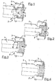
- the electrical contact arrangement as shown in Fig. 1 principally consists of a contact arm 1, which is designed as a hollow cylinder consisting of copper or aluminium material. On its left side the contact arm 1 is mechanically connected to a - not shown - medium voltage circuit breaker pole part. On its right side the contact arm 1 is provided with a special distal end section 2 on which a circular shaped annulus arrangement is arranged.
- the special annulus arrangement consists of several axially and parallel directed contact fingers 3 (exemplary). Each contact finger 3 is pressed on the distal end section 2 of the contact arm 1 via a radially directed connection section 4 by a spring ring 5.
- the spring ring 5 is peripherally arranged around the contact fingers 3.
- the distal end section 2 of the contact arm 1 comprises a first ring-shaped surface 6a and an adjacent second ring-shaped surface 6b forming a L-shaped groove 7 on the distal end section 2 of the contact arm 1.
- the connection section 4 of each contact finger 3 is pressed to both ring-shaped surfaces 6a and 6b.
- an additional spring ring 8 is provided which generates a spring force in the axial direction.
- the additional spring ring 8 is secured onto the front side of the contact arm 1 by a screw element 9 screwed into the hollow section of the tubular contact arm 1.
- the additional spring ring 8 as well as the other spring ring 5 are designed as spiral springs in the shown embodiment.
- the additional spring ring 8' is designed as a washer spring for generating the axially directed pressing force to the contact fingers 3.
- the additional spring ring 8' is also fixed to the distal end section 2 of the contact arm 1 by a screw element 9.
- a first ring-shaped surface 6b' and a second ring-shaped surface 6a' forms a V-shaped groove 7' on the distal end section 2 of the contact arm 1. Only one spring ring 5 is necessary in order to press each contact finger 3 into the V-shaped groove 7'.
- the V-shaped groove 7' corresponds to a curve-shaped connection section 4' of each contact finger 3.
- the V-shaped groove 7" is provided with an asymmetrical cross-section in order to increase the portion of the force generated by the other spring ring 5 to that side where main current path is disposed in order to optimize the ohmic resistance and the contact resistance of the electrical contact arrangement.
- the contact fingers 3 will extend to the right side to another contact of the medium voltage switchgear panel, typically a connection to the busbar or to a cable, which is not shown in the Figures.
Landscapes
- Trip Switchboards (AREA)
- Contacts (AREA)
Abstract
The invention relates to an electrical contact arrangement for medium to high voltage applications comprising a contact arm (1) having a distal end section (2) on which a circular shaped annulus arrangement consisting of several axially and parallel directed contact fingers (3) is arranged, which are pressed on the contact arm (1) via respective radially directed connection sections (4) by a spring ring (5) which is peripherally arranged around the contact fingers (3), wherein the distal end section (2) of the contact arm (1) comprises a first ring-shaped surface (6b) and an adjacent second ring-shaped surface (6a), so that the connection section (4) of each contact finger (3) is pressed to at least both ring-shaped surfaces (6a, 6b).
Description
- The present invention relates to an electrical contact arrangement for medium to high voltage applications comprising a contact arm having a distal end section on which a circular shaped annulus arrangement consisting of several axially and parallel directed contact fingers is arranged, which are pressed on the contact arm via respective radially directed connection sections by a spring ring which is peripherally arranged around the contact fingers.
- Medium voltage circuit breakers interrupt the current by creating and extinguishing the arc in a vacuum container. Modern vacuum circuit breakers tend to have longer life expectancy than former air or SF6 circuit-breakers. Vacuum circuit breakers replaced air and SF6 circuit breakers at least for indoor applications. However, the present invention is directed to all kinds of circuit breakers in the range of medium voltage to high voltage applications, especially for electrical connectors in air insulated medium voltage switch gear panels. Such switch gear panels require means or contact systems to connect and disconnect the electrical circuit to busbar terminals and cable terminals of the panel when they are being inserted and removed, respectively. Therefore, special electrical contact arrangements are provided having several contact fingers forming a circular crown-shaped arrangement for electrically connecting a distal end section of a contact arm to the busbar terminal in the panel.
- The document
DE 196 48 633 A1 discloses an electrical contact arrangement for high voltage applications comprising an annulus arrangement consisting of several axially and parallel directed contact fingers which are separated one to another by intermediate slits. The contact fingers are designed as respective sections of a one-piece sleeve part, which is mechanically and electrically connected to the distal end of a contact arm. - According to other known embodiments of electrical contact arrangements the contact fingers are designed as single pieces. For a sufficient electromechanical contact to the contact arm, these single fingers are pressed with a surrounding spring ring onto a ring-shaped surface on the distal end section of the contact arm. Since the single contact fingers also have to be pressed onto the terminal in the panel the same spring ring also acts in axial direction. Therefore, each contact finger is angled. Usually, there are additional means for supporting the structure of the contact fingers and the ring spring in order to form a mechanically stable but elastic electrical contact arrangement. The pressing of the contact fingers onto the contact arm by the ring spring is important both to reduce the electrical resistance for passing the temperature rise typetest, and to obtain the required mechanical stability to pass the short time withstand current typetest.
- Usually, only the ring-shaped surface on the end section of the contact arm comes in contact to the corresponding section of the contact fingers.
- It is an object of the present invention to provide an electrical contact arrangement using a circular-shaped annulus arrangement consisting of several axially and parallel directed contact fingers having an increased mechanically stability without influences on the required resilience of the single contact fingers.
- According to the invention the distal end section of the contact arm comprises a first ring-shaped surface and an adjacent second ring-shaped surface, wherein the connection section of each contact finger is pressed to at least both ring-shaped surfaces.
- The advantage of this special technical solution is a reduced ohmic resistance and a reduced contact resistance as a parallel path for the current is being established by the second ring-shaped surface of the contact arm. An additional result will be a lower rise of temperature of the electrical contact arrangement during the temperature rise typetest. This advantage can also be used to save some material of the contact arm and of a part of the contact arrangement. Further, there is an advantage under short-circuit conditions due to the doubled number of connection points. The risk of overheating of one connection point is reduced as the average current is lower for each connection point. The result will be a better performance during the short time withstand current type test.
- Preferably, the other spring ring which surrounds the annulus arrangement of the contact fingers is provided to press the connection section of each contact finger to the first ring-shaped surface that means in radial direction. The additional spring ring is provided to press the connection section of the contact fingers to the second ring-shaped surface, which runs in another direction than the first ring-shaped surface.
- According to a first preferred embodiment of the invention the first ring-shaped surface and the second ring-shaped surface form a L-shaped groove on the distal end section of the contact arm. Such a L-shaped groove can be provided by adjacent sections of different diameters on the distal end of the contact arm.
- The special L-shaped groove preferably corresponds to a rectangular-shaped connection section of the contact finger, wherein the L-shaped groove corresponds with the other spring ring as well as with the additional spring ring for pressing the contact fingers against both ring-shaped surfaces.
- A spring ring can be of any suitable kind to provide both the required force and the required elasticity of the contact arrangement. For example, a spiral spring is suitable for the first spring ring as well as for the additional spring ring. Furthermore, in a second embodiment, it is possible to use a spring washer for the additional spring ring which generates an axially directed force to the contact fingers. Preferably, an additional screw element is axially screwed into the front side of the contact arm in order to attach the additional spring ring to the second ring-shaped surface of the L-shaped groove.
- According to a third embodiment of the invention the first ring-shaped surface and the second ring-shaped surface forms a V-shaped groove on the distal end section of the contact arm. The V-shaped groove preferably corresponds to a curve-shaped connection section of the contact finger in order to establish a contact point on the first ring-shaped surface as well as on the second ring-shaped surface. The main advantage of the V-shaped groove is, that only one spring ring is necessary for pressing the contact fingers to the contact arm. Therefore, the V-shaped groove is radially directed in relation to the contact arm axis. Furthermore, an additional screw element is not necessary on that embodiment.
- The V-shaped groove has a preferably symmetrical cross-section. However, in a fourth embodiment, it is also possible to provide the V-shaped groove with an asymmetrical cross-section. An asymmetrical cross-section preferrably increases the portion of the force generated by the spring ring that presses the contact fingers to that side where the main current path is arranged in order to optimize the ohmic resistance and the contact resistance of the electrical contact arrangement.
- The foregoing and other aspects of the invention will become apparent following the detailed description of the invention when consider it in conjunction with the enclosed drawings.
-
- Fig. 1
- is a perspective side view of a first embodiment of the electrical contact arrangement in a L-groove version,
- Fig. 2
- is a perspective side view of a second embodiment of the electrical contact arrangement in an L-groove version,
- Fig. 3
- is a perspective side view of a third embodiment of the invention in a symmetrical V-groove version, and
- Fig. 4
- is a perspective side view of a forth embodiment of the invention in an asymmetrical V-groove version.
- The electrical contact arrangement as shown in
Fig. 1 principally consists of a contact arm 1, which is designed as a hollow cylinder consisting of copper or aluminium material. On its left side the contact arm 1 is mechanically connected to a - not shown - medium voltage circuit breaker pole part. On its right side the contact arm 1 is provided with a special distal end section 2 on which a circular shaped annulus arrangement is arranged. The special annulus arrangement consists of several axially and parallel directed contact fingers 3 (exemplary). Each contact finger 3 is pressed on the distal end section 2 of the contact arm 1 via a radially directed connection section 4 by aspring ring 5. Thespring ring 5 is peripherally arranged around the contact fingers 3. - The distal end section 2 of the contact arm 1 comprises a first ring-shaped surface 6a and an adjacent second ring-shaped surface 6b forming a L-
shaped groove 7 on the distal end section 2 of the contact arm 1. The connection section 4 of each contact finger 3 is pressed to both ring-shaped surfaces 6a and 6b. For pressing the connection section to the first ring-shaped surface 6a an additional spring ring 8 is provided which generates a spring force in the axial direction. The additional spring ring 8 is secured onto the front side of the contact arm 1 by ascrew element 9 screwed into the hollow section of the tubular contact arm 1. The additional spring ring 8 as well as theother spring ring 5 are designed as spiral springs in the shown embodiment. - According to
Fig. 2 the additional spring ring 8' is designed as a washer spring for generating the axially directed pressing force to the contact fingers 3. The additional spring ring 8' is also fixed to the distal end section 2 of the contact arm 1 by ascrew element 9. - In view of
Fig. 3 a first ring-shaped surface 6b' and a second ring-shaped surface 6a' forms a V-shapedgroove 7' on the distal end section 2 of the contact arm 1. Only onespring ring 5 is necessary in order to press each contact finger 3 into the V-shapedgroove 7'. The V-shapedgroove 7' corresponds to a curve-shaped connection section 4' of each contact finger 3. - According to
Fig. 4 the V-shapedgroove 7" is provided with an asymmetrical cross-section in order to increase the portion of the force generated by theother spring ring 5 to that side where main current path is disposed in order to optimize the ohmic resistance and the contact resistance of the electrical contact arrangement. - The contact fingers 3 will extend to the right side to another contact of the medium voltage switchgear panel, typically a connection to the busbar or to a cable, which is not shown in the Figures.
- Reference signs
- 1
- Contact arm
- 2
- Distal end section
- 3
- Contact finger
- 4
- Connection section
- 5
- Spring ring
- 6
- Ring-shaped surface
- 7
- L-shaped groove
- 8
- Additional spring ring
- 9
- Screw element
Claims (14)
- Electrical contact arrangement for medium to high voltage applications comprising a contact arm (1) having a distal end section (2) on which a circular shaped annulus arrangement consisting of several axially and parallel directed contact fingers (3) is arranged, which are pressed on the contact arm (1) via respective radially directed connection sections (4) by a spring ring (5) which is peripherally arranged around the contact fingers (3),
characterised in that the distal end section (2) of the contact arm (1) comprises a first ring-shaped surface (6b) and an adjacent second ring-shaped surface (6a), wherein the connection section (4) of each contact finger (3) is pressed to at least both ring-shaped surfaces (6a, 6b). - Electrical contact arrangement according to Claim 1,
characterised in that the outer spring ring (5) is provided to press the connection section (4) of the contact fingers (3) to the first ring-shaped surface (6b) and an additional spring ring (8) is provided to press the connection section (4) of the contact fingers (3) to the second ring-shaped surface (6a). - Electrical contact arrangement according to Claim 2,
characterised in that the outer spring ring (5) and/or the additional spring ring (8) are/is formed as a spiral spring. - Electrical contact arrangement according to Claim 1 or 2,
characterised in that the first ring-shaped surface (6b) and the second ring-shaped surface (6a) forms a L-shaped groove (7) on the distal end section (2) of the contact arm (1). - Electrical contact arrangement according to Claim 4,
characterised in that the L-shaped groove (7) corresponds to a rectangular-shaped connection section (4) of the contact finger (3). - Electrical contact arrangement according to Claim 2,
characterised in that the L-shaped groove (7) corresponds with the outer spring ring (5) as well as with the additional spring ring (8) for pressing the contact fingers (3) to the contact arm (1). - Electrical contact arrangement according to Claim 2,
characterised in that the additional spring ring (8') is designed as a washer spring for generating an axially directed pressing force to the contact fingers (3). - Electrical contact arrangement according to Claim 4,
characterised in that a screw element (9) is axially screwed into the front side of the contact arm (1) in order to attach the additional spring ring (8) to the second ring-shaped surface (6b) of the L-shaped groove (7). - Electrical contact arrangement according to Claim 1 or 2,
caracterised in that the first ring-shaped surface (6b') and the second ring-shaped surface (6a') forms a V-shaped groove (7') on the distal end section (2) of the contact arm (1). - Electrical contact arrangement according to Claim 9,
characterised in that the V-shaped groove (7') corresponds to a curve-shaped connection section (4') of the contact finger (3). - Electrical contact arrangement according to Claim 9,
characterised in that the V-shaped groove (7') only corresponds with the outer spring ring (5) for pressing the contact fingers (3) to the contact arm (1). - Electrical contact arrangement according to Claim 9,
characterised in that the V-shaped groove (7") is provided with an asymmetrically cross section. - Electrical contact arrangement according to one of the preceeding Claims, characterised in that the contact arm (1) consists of a copper or an aluminum material.
- Air insulated medium voltage circuit breaker comprising at least one electrical pole part which is electrically connected to at least one pushbar terminal and/or cabel terminal by an electrical contact arrangement according to one of the preceeding Claims.
Priority Applications (4)
| Application Number | Priority Date | Filing Date | Title |
|---|---|---|---|
| EP10008456A EP2418666A1 (en) | 2010-08-13 | 2010-08-13 | Electrical contact arrangement, especially for an air insulated medium voltage circuit breaker |
| PCT/EP2011/004058 WO2012019773A1 (en) | 2010-08-13 | 2011-08-12 | Electrical contact arrangement, especially for an air insulated medium voltage circuit breaker |
| CN201180045993.9A CN103155072B (en) | 2010-08-13 | 2011-08-12 | Electrical contact devices especially for air-insulated medium voltage circuit breakers |
| US13/766,389 US9263199B2 (en) | 2010-08-13 | 2013-02-13 | Electrical contact arrangement and air insulated medium voltage circuit breaker including the electrical contact arrangement |
Applications Claiming Priority (1)
| Application Number | Priority Date | Filing Date | Title |
|---|---|---|---|
| EP10008456A EP2418666A1 (en) | 2010-08-13 | 2010-08-13 | Electrical contact arrangement, especially for an air insulated medium voltage circuit breaker |
Publications (1)
| Publication Number | Publication Date |
|---|---|
| EP2418666A1 true EP2418666A1 (en) | 2012-02-15 |
Family
ID=43382434
Family Applications (1)
| Application Number | Title | Priority Date | Filing Date |
|---|---|---|---|
| EP10008456A Withdrawn EP2418666A1 (en) | 2010-08-13 | 2010-08-13 | Electrical contact arrangement, especially for an air insulated medium voltage circuit breaker |
Country Status (4)
| Country | Link |
|---|---|
| US (1) | US9263199B2 (en) |
| EP (1) | EP2418666A1 (en) |
| CN (1) | CN103155072B (en) |
| WO (1) | WO2012019773A1 (en) |
Cited By (3)
| Publication number | Priority date | Publication date | Assignee | Title |
|---|---|---|---|---|
| EP2835806A1 (en) * | 2013-08-05 | 2015-02-11 | ABB Technology AG | High voltage interrupter unit with improved mechanical endurance |
| WO2015032538A1 (en) * | 2013-09-05 | 2015-03-12 | Robert Bosch Gmbh | Pressing element, electrical/electronic component |
| EP3109880A1 (en) * | 2015-06-22 | 2016-12-28 | ABB Schweiz AG | Medium- or high voltage pole part with at least one heat sink element |
Families Citing this family (12)
| Publication number | Priority date | Publication date | Assignee | Title |
|---|---|---|---|---|
| WO2014179718A1 (en) * | 2013-05-03 | 2014-11-06 | Ppc Broadband, Inc. | Interface terminating device |
| CN104916488A (en) * | 2014-03-13 | 2015-09-16 | 上海正昊电力科技有限公司 | Disconnecting switch |
| US10242825B1 (en) * | 2014-09-16 | 2019-03-26 | Cleaveland/Price Inc. | High voltage switch vacuum interrupter |
| WO2016069570A2 (en) * | 2014-10-27 | 2016-05-06 | Fci Asia Pte. Ltd | Circular power connectors |
| CN107293438B (en) * | 2016-04-12 | 2019-09-06 | 闫淼江 | A kind of contact assembly and its negative contact of high voltage isolator |
| EP3270395B1 (en) * | 2016-07-15 | 2021-01-27 | ABB Schweiz AG | Vibration-limiting device for an apparatus comprising a switchgear and a switching device, such as a circuit breaker, and apparatus comprising said vibration-limiting device |
| CN107633976B (en) * | 2016-07-19 | 2019-12-06 | 闫淼江 | High-voltage isolating switch, fracture assembly thereof and method for manufacturing female contact |
| CN107946099A (en) * | 2017-10-25 | 2018-04-20 | 宁波中迪机械有限公司 | A kind of electrical connection module |
| CN107946812A (en) * | 2017-10-25 | 2018-04-20 | 宁波中迪机械有限公司 | Electrical connection module |
| CN107706036A (en) * | 2017-10-25 | 2018-02-16 | 宁波中迪机械有限公司 | Fingertip component |
| CN107749356B (en) * | 2017-10-25 | 2021-05-18 | 宁波中迪机械有限公司 | Contact finger assembly |
| US12525755B2 (en) | 2021-07-19 | 2026-01-13 | Fci Usa Llc | Power connector for compact electronic systems |
Citations (4)
| Publication number | Priority date | Publication date | Assignee | Title |
|---|---|---|---|---|
| FR2478866A1 (en) * | 1980-03-24 | 1981-09-25 | Merlin Gerin | Rotating arc AC circuit breaker with magnetic arc force - uses hollow cylindrical ends on contacts to keep arc close to encircling magnet having circuit shaped to draw arc away |
| US4371765A (en) * | 1979-05-25 | 1983-02-01 | Bbc Brown, Boveri & Company, Ltd. | Electrical switch for large currents |
| DE4105335A1 (en) * | 1991-02-18 | 1992-08-20 | Siemens Ag | Electric contact system for durable multiple switching - includes pre-contact connected to lamina lifted by pressure of counter contact on lamina |
| DE19648633A1 (en) | 1996-11-25 | 1998-05-28 | Asea Brown Boveri | Electrical switching device |
Family Cites Families (10)
| Publication number | Priority date | Publication date | Assignee | Title |
|---|---|---|---|---|
| US2176718A (en) * | 1936-12-12 | 1939-10-17 | Gen Electric | Electric disconnecting device |
| JPS6182367U (en) * | 1984-11-06 | 1986-05-31 | ||
| JPS61233915A (en) * | 1985-04-04 | 1986-10-18 | 三菱電機株式会社 | disconnector |
| JPH05290902A (en) * | 1992-04-10 | 1993-11-05 | Mitsubishi Electric Corp | Conductor contact device |
| JPH10223276A (en) * | 1997-02-05 | 1998-08-21 | Mitsubishi Electric Corp | Contact device |
| JPH1131441A (en) * | 1997-07-11 | 1999-02-02 | Mitsubishi Electric Corp | Terminal connection device |
| JP2898617B1 (en) * | 1998-01-12 | 1999-06-02 | 光利 渡邊 | Power cable connector |
| JP4399479B2 (en) * | 2007-05-25 | 2010-01-13 | 三菱電機株式会社 | Terminal connection device |
| KR101013688B1 (en) * | 2008-12-04 | 2011-02-10 | 엘에스산전 주식회사 | Tulip contact of vacuum breaker |
| CN101661848A (en) * | 2009-10-09 | 2010-03-03 | 闫淼江 | Contact assembly of isolating switch |
-
2010
- 2010-08-13 EP EP10008456A patent/EP2418666A1/en not_active Withdrawn
-
2011
- 2011-08-12 WO PCT/EP2011/004058 patent/WO2012019773A1/en not_active Ceased
- 2011-08-12 CN CN201180045993.9A patent/CN103155072B/en not_active Expired - Fee Related
-
2013
- 2013-02-13 US US13/766,389 patent/US9263199B2/en not_active Expired - Fee Related
Patent Citations (4)
| Publication number | Priority date | Publication date | Assignee | Title |
|---|---|---|---|---|
| US4371765A (en) * | 1979-05-25 | 1983-02-01 | Bbc Brown, Boveri & Company, Ltd. | Electrical switch for large currents |
| FR2478866A1 (en) * | 1980-03-24 | 1981-09-25 | Merlin Gerin | Rotating arc AC circuit breaker with magnetic arc force - uses hollow cylindrical ends on contacts to keep arc close to encircling magnet having circuit shaped to draw arc away |
| DE4105335A1 (en) * | 1991-02-18 | 1992-08-20 | Siemens Ag | Electric contact system for durable multiple switching - includes pre-contact connected to lamina lifted by pressure of counter contact on lamina |
| DE19648633A1 (en) | 1996-11-25 | 1998-05-28 | Asea Brown Boveri | Electrical switching device |
Cited By (8)
| Publication number | Priority date | Publication date | Assignee | Title |
|---|---|---|---|---|
| EP2835806A1 (en) * | 2013-08-05 | 2015-02-11 | ABB Technology AG | High voltage interrupter unit with improved mechanical endurance |
| WO2015032538A1 (en) * | 2013-09-05 | 2015-03-12 | Robert Bosch Gmbh | Pressing element, electrical/electronic component |
| CN105518938A (en) * | 2013-09-05 | 2016-04-20 | 罗伯特·博世有限公司 | Pressing element, electrical/electronic component |
| KR20160048782A (en) * | 2013-09-05 | 2016-05-04 | 로베르트 보쉬 게엠베하 | Pressing element, electrical/electronic component |
| US20160204525A1 (en) * | 2013-09-05 | 2016-07-14 | Robert Bosch Gmbh | Pressing Element, Electrical/Electronic Component |
| US9812792B2 (en) | 2013-09-05 | 2017-11-07 | Robert Bosch Gmbh | Pressing element, electrical/electronic component |
| CN105518938B (en) * | 2013-09-05 | 2018-08-14 | 罗伯特·博世有限公司 | It is pressed element, electrical/electronic component |
| EP3109880A1 (en) * | 2015-06-22 | 2016-12-28 | ABB Schweiz AG | Medium- or high voltage pole part with at least one heat sink element |
Also Published As
| Publication number | Publication date |
|---|---|
| WO2012019773A1 (en) | 2012-02-16 |
| CN103155072B (en) | 2015-11-25 |
| CN103155072A (en) | 2013-06-12 |
| US9263199B2 (en) | 2016-02-16 |
| US20130146433A1 (en) | 2013-06-13 |
Similar Documents
| Publication | Publication Date | Title |
|---|---|---|
| EP2418666A1 (en) | Electrical contact arrangement, especially for an air insulated medium voltage circuit breaker | |
| US5981893A (en) | Electrical switching device | |
| EP2465125B1 (en) | Tulip contact and electrical contact system for switching device | |
| EP2693573B1 (en) | Power circuit electrical connection system and method | |
| EP2833385A1 (en) | Connecting device for a switchgear apparatus | |
| US7884298B2 (en) | Switch for a switchgear assembly for power supply and distribution | |
| US20070246444A1 (en) | Contact system for an electrical switching device | |
| EP2077569A1 (en) | Vacuum switchgear | |
| EP2562777B1 (en) | Dual structured contact for switchgear and switchgear having the same | |
| CN1178254C (en) | Vacuum switch chamber with ring insulator | |
| CN111952111B (en) | Double-fracture quick vacuum arc extinguish chamber | |
| RU2634749C2 (en) | Coil of axial magnetic field for vacuum interrupter | |
| EP2434508B1 (en) | Electrical contact arrangement with annulus unit consisting of contact fingers | |
| SE442567B (en) | ELECTRICAL CONNECTION DEVICE BETWEEN TWO CONDUCTORS A | |
| JP2011103768A (en) | Connection of power cable | |
| EP3404679A1 (en) | Tulip-type electrical contact comprising a pressing element pressing on the conducting fingers at rest | |
| CN108321004B (en) | Pole post | |
| CA2833486C (en) | Electrical medium or high voltage switching device | |
| US2728056A (en) | Jumper for interconnecting spaced electric terminals | |
| WO2010098699A1 (en) | Device for integration of the movable current collector in the vacuum arc - quenching chamber with a circuit breaker terminal | |
| CN210403586U (en) | Transformer neutral point isolating switch | |
| CN214626072U (en) | Electrode contact arm for electrode unit, electrode unit for switching device, and switching device | |
| JPH05282969A (en) | Gas circuit breaker | |
| EP4411773A1 (en) | Ring-shaped coil spring of switchgear and switchgear using same | |
| EP2731117A1 (en) | High voltage electrical switching device with supporting tube |
Legal Events
| Date | Code | Title | Description |
|---|---|---|---|
| AK | Designated contracting states |
Kind code of ref document: A1 Designated state(s): AL AT BE BG CH CY CZ DE DK EE ES FI FR GB GR HR HU IE IS IT LI LT LU LV MC MK MT NL NO PL PT RO SE SI SK SM TR |
|
| AX | Request for extension of the european patent |
Extension state: BA ME RS |
|
| PUAI | Public reference made under article 153(3) epc to a published international application that has entered the european phase |
Free format text: ORIGINAL CODE: 0009012 |
|
| 17P | Request for examination filed |
Effective date: 20120816 |
|
| 17Q | First examination report despatched |
Effective date: 20160415 |
|
| STAA | Information on the status of an ep patent application or granted ep patent |
Free format text: STATUS: THE APPLICATION IS DEEMED TO BE WITHDRAWN |
|
| 18D | Application deemed to be withdrawn |
Effective date: 20160826 |