EP2418476A1 - Verfahren zur filmlosen Durchstrahlungsprüfung von Bauteilen - Google Patents
Verfahren zur filmlosen Durchstrahlungsprüfung von Bauteilen Download PDFInfo
- Publication number
- EP2418476A1 EP2418476A1 EP11006443A EP11006443A EP2418476A1 EP 2418476 A1 EP2418476 A1 EP 2418476A1 EP 11006443 A EP11006443 A EP 11006443A EP 11006443 A EP11006443 A EP 11006443A EP 2418476 A1 EP2418476 A1 EP 2418476A1
- Authority
- EP
- European Patent Office
- Prior art keywords
- component
- ray
- digital
- radiation
- virtual
- Prior art date
- Legal status (The legal status is an assumption and is not a legal conclusion. Google has not performed a legal analysis and makes no representation as to the accuracy of the status listed.)
- Granted
Links
- 238000000034 method Methods 0.000 title claims abstract description 9
- 238000012360 testing method Methods 0.000 title description 3
- 238000010521 absorption reaction Methods 0.000 claims abstract description 8
- 230000000295 complement effect Effects 0.000 claims abstract description 3
- 238000004441 surface measurement Methods 0.000 claims abstract 2
- 230000005855 radiation Effects 0.000 claims description 21
- 230000007547 defect Effects 0.000 claims description 12
- 239000000463 material Substances 0.000 claims description 12
- 238000001514 detection method Methods 0.000 claims description 5
- 238000012876 topography Methods 0.000 claims description 4
- 230000000149 penetrating effect Effects 0.000 claims description 2
- 206010000234 Abortion spontaneous Diseases 0.000 claims 1
- 238000005259 measurement Methods 0.000 claims 1
- 208000015994 miscarriage Diseases 0.000 claims 1
- 208000000995 spontaneous abortion Diseases 0.000 claims 1
- 229910000831 Steel Inorganic materials 0.000 abstract description 2
- 239000010959 steel Substances 0.000 abstract description 2
- VNNRSPGTAMTISX-UHFFFAOYSA-N chromium nickel Chemical compound [Cr].[Ni] VNNRSPGTAMTISX-UHFFFAOYSA-N 0.000 abstract 1
- 238000011156 evaluation Methods 0.000 description 4
- 238000009499 grossing Methods 0.000 description 4
- 238000005516 engineering process Methods 0.000 description 3
- 230000001788 irregular Effects 0.000 description 2
- 238000005204 segregation Methods 0.000 description 2
- 230000001419 dependent effect Effects 0.000 description 1
- 238000011161 development Methods 0.000 description 1
- 230000018109 developmental process Effects 0.000 description 1
- 238000003384 imaging method Methods 0.000 description 1
- 230000013011 mating Effects 0.000 description 1
- 239000011148 porous material Substances 0.000 description 1
- 238000004154 testing of material Methods 0.000 description 1
Images
Classifications
-
- G—PHYSICS
- G01—MEASURING; TESTING
- G01N—INVESTIGATING OR ANALYSING MATERIALS BY DETERMINING THEIR CHEMICAL OR PHYSICAL PROPERTIES
- G01N23/00—Investigating or analysing materials by the use of wave or particle radiation, e.g. X-rays or neutrons, not covered by groups G01N3/00 – G01N17/00, G01N21/00 or G01N22/00
- G01N23/02—Investigating or analysing materials by the use of wave or particle radiation, e.g. X-rays or neutrons, not covered by groups G01N3/00 – G01N17/00, G01N21/00 or G01N22/00 by transmitting the radiation through the material
- G01N23/06—Investigating or analysing materials by the use of wave or particle radiation, e.g. X-rays or neutrons, not covered by groups G01N3/00 – G01N17/00, G01N21/00 or G01N22/00 by transmitting the radiation through the material and measuring the absorption
- G01N23/18—Investigating the presence of flaws defects or foreign matter
-
- G—PHYSICS
- G01—MEASURING; TESTING
- G01N—INVESTIGATING OR ANALYSING MATERIALS BY DETERMINING THEIR CHEMICAL OR PHYSICAL PROPERTIES
- G01N23/00—Investigating or analysing materials by the use of wave or particle radiation, e.g. X-rays or neutrons, not covered by groups G01N3/00 – G01N17/00, G01N21/00 or G01N22/00
- G01N23/02—Investigating or analysing materials by the use of wave or particle radiation, e.g. X-rays or neutrons, not covered by groups G01N3/00 – G01N17/00, G01N21/00 or G01N22/00 by transmitting the radiation through the material
- G01N23/06—Investigating or analysing materials by the use of wave or particle radiation, e.g. X-rays or neutrons, not covered by groups G01N3/00 – G01N17/00, G01N21/00 or G01N22/00 by transmitting the radiation through the material and measuring the absorption
- G01N23/083—Investigating or analysing materials by the use of wave or particle radiation, e.g. X-rays or neutrons, not covered by groups G01N3/00 – G01N17/00, G01N21/00 or G01N22/00 by transmitting the radiation through the material and measuring the absorption the radiation being X-rays
-
- G—PHYSICS
- G01—MEASURING; TESTING
- G01N—INVESTIGATING OR ANALYSING MATERIALS BY DETERMINING THEIR CHEMICAL OR PHYSICAL PROPERTIES
- G01N2223/00—Investigating materials by wave or particle radiation
- G01N2223/40—Imaging
- G01N2223/41—Imaging imaging specifically internal structure
Definitions
- the invention relates to a method for the filmless radiographic examination of components by means of X-rays on the basis of a different by internal material error radiation absorption and intensity of radiation detected by the irradiation of the component of a digital X-ray detector radiation, wherein the digitized radiation signals are processed in a computer and on a screen generate a digitalized x-ray image.
- the radiographic examination by means of digital X-ray technology is an imaging method for nondestructive material testing, in which a component to be tested is irradiated with X-rays generated by an X-ray tube and the X-rays are detected by the radiation of the component of an X-ray camera (X-ray detector).
- X-ray detector X-ray detector
- the x-ray detector signal is permanently read and processed and digitized in a computer to display a digital x-ray image of the workpiece being examined on a computer-connected screen.
- edge blurring that is to say a half-shadow area present around the defect
- a low contrast blackening difference
- an irregular surface structure of the component to be examined for example in the form of surface pores, leads primarily to reduced radiation absorption and correspondingly high radiation intensity.
- the blackening thus generated on the screen are not relevant material errors, but rather falsify the test result or allow an exact detection of material defects on the screen or a safe automatic evaluation of the X-ray images.
- the invention has for its object to provide a method for radiographic testing of components with digital X-ray technology, which ensures reliable detection of existing defects in the component material.
- the X-ray examination of components by means of X-rays takes place on the basis of a radiation error due to material defects in the component and the intensity of the radiation signals detected after the component has been irradiated by an X-ray detector or an X-ray camera, which after digitalization and evaluation in a computer acquire a digital X-ray image with different X-ray images Create grayscale on a screen.
- the core of the invention is that an uneven, also different radiation intensities causing surface topography of the component, which complicates an automatic evaluation of the X-ray image and the reliable detection of material defects, is superimposed with a digital smoothing layer and is purely computationally smoothed, so that a reduction of Radiation absorption or an increase in the radiation intensity due to an uneven surface topography balanced and only a caused by internal material defects blackening in the digital X-ray image is displayed.
- a reduction of Radiation absorption or an increase in the radiation intensity due to an uneven surface topography balanced and only a caused by internal material defects blackening in the digital X-ray image is displayed.
- an exact, unevaluated by surface irregularities automated radiographic examination is possible, which is particularly important for safety-critical components of crucial importance.
- the generation of the digital smoothing layer takes place in such a way that, parallel to the X-ray detection with the digital X-ray camera, the surface of the component to be examined is scanned with a digital X-ray scanner or laser scanner and the digital signals of the X-ray camera are superimposed on the digital surface scanning signals of the scanner in the computer.
- the pure surface topography signals detected by the scanner are calculated out in the computer from the totality of the X-ray signals detected by the digital X-ray camera so that the digital X-ray image of a component with smooth flat surface is reproduced on the screen and material defects in the component such as imperfections, inclusions, segregations , Gas bubbles, cracks or mating errors are reliably detected even with automatic evaluation of the digital X-ray images.
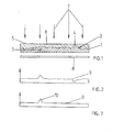
- An example of 18.8-chromium-nickel steel existing component 1 has an uneven surface geometry 2 and in the interior of the workpiece to be tested expected error 3.
- the surface geometry 2 of the component 1 is measured with a measuring device, in this case a laser scanner (not shown), and a virtually smoothed surface 5 is numerically defined on the basis of the highest survey 4 ascertained.
- the complementary 3D element 6 virtual smoothing layer
- the complementary 3D element 6 that arises between the smooth virtual surface 5 and the uneven actual surface geometry 2 is supplemented with a specific X-ray absorption coefficient matched to the component material.
- the component 1 is examined using digital X-ray technology, that is to say filmless with an X-ray 7 generated by an X-ray tube and an X-ray detector 8 (digital X-ray camera) detecting the X-ray 7 penetrating the component 1.
- the digital radiation signals generated by the X-ray detector 8 are superimposed with the 3D element 6 with virtual surface 5, which is generated on the basis of the digital surface measuring signals of the laser scanner, so that on a computer connected to the computer Screen (not shown) only one on the basis of a virtual smooth surface 5 generated, independent of an uneven surface structure X-ray image 9 with a visually or automatically easily recognizable Schwärzungsspitze 10 (FIG. Fig. 3 ) is displayed to indicate an existing in the component 1 error 3.
- Fig. 2 shows the blurred darkness without virtual surface smoothing.
Landscapes
- Health & Medical Sciences (AREA)
- Physics & Mathematics (AREA)
- Life Sciences & Earth Sciences (AREA)
- Chemical & Material Sciences (AREA)
- Analytical Chemistry (AREA)
- Biochemistry (AREA)
- General Health & Medical Sciences (AREA)
- General Physics & Mathematics (AREA)
- Immunology (AREA)
- Pathology (AREA)
- Toxicology (AREA)
- Analysing Materials By The Use Of Radiation (AREA)
Abstract
Description
- Die Erfindung betrifft ein Verfahren zur filmlosen Durchstrahlungsprüfung von Bauteilen mittels Röntgenstrahlen auf der Grundlage einer durch innere Materialfehler unterschiedlichen Strahlungsabsorption und Intensität der nach der Durchstrahlung des Bauteils von einem digitalen Röntgenstrahldetektor detektierten Strahlung, wobei die digitalisierten Strahlungssignale in einem Computer verarbeitet werden und auf einem Bildschirm ein digitalisiertes Röntgenbild erzeugen.
- Die Durchstrahlungsprüfung mittels digitaler Röntgentechnik ist ein bildgebendes Verfahren zur zerstörungsfreien Werkstoffprüfung, bei dem ein zu prüfendes Bauteil mit von einer Röntgenröhre erzeugten Röntgenstrahlen durchstrahlt wird und die Röntgenstrahlen nach der Durchstrahlung des Bauteils von einer Röntgenkamera (Röntgenstrahldetektor) erfasst werden. Bei der Bewegung der Röntgenstrahlquelle und der Röntgenkamera relativ zu dem Bauteil (oder umgekehrt) wird das Signal des Röntgenstrahldetektors permanent ausgelesen und in einem Computer verarbeitet und digitalisiert, um auf einem mit dem Computer verbundenen Bildschirm ein digitales Röntgenbild des untersuchten Werkstücks darzustellen. Aufgrund unterschiedlicher Strahlungsabsorption und entsprechend unterschiedlicher Strahlungsschwächung können in dem Bauteil vorhandene Fehlstellen, Einschlüsse, Seigerungen, Gasblasen, Risse oder Fügungsfehler in Form einer durch die größere Strahlungsintensität bedingten stärkeren Schwärzung auf dem Bildschirm erkennbar gemacht werden.
- Die Erkennbarkeit von Materialfehlern wird durch eine Randunschärfe, das heißt ein rings um die Fehlerstelle vorhandenes Halbschattengebiet, und einen geringen Kontrast (Schwärzungsunterschied), die durch eine Streustrahlung der auf eine unregelmäßige Bauteiloberfläche auftreffenden elektromagnetischen Wellen bedingt sein können, verringert. Eine unregelmäßige Oberflächenstruktur des zu untersuchenden Bauteils, beispielsweise in Form von Oberflächenporen, führt jedoch in erster Linie zu verminderter Strahlungsabsorption und dementsprechend hoher Strahlungsintensität. Die dadurch auf dem Bildschirm erzeugten Schwärzungen stellen jedoch keine relevanten Materialfehler dar, sondern verfälschen vielmehr das Prüfungsergebnis bzw. lassen eine exakte Erkennung von Materialfehlern auf dem Bildschirm bzw. eine sichere automatische Auswertung der Röntgenbilder nicht zu.
- Der Erfindung liegt die Aufgabe zugrunde, ein Verfahren zur Durchstrahlungsprüfung von Bauteilen mit digitaler Röntgentechnik anzugeben, das eine sichere Erkennung von in dem Bauteilmaterial vorhandenen Fehlstellen gewährleistet.
- Erfindungsgemäß wird die Aufgabe mit einem Verfahren gemäß den Merkmalen des Patentanspruchs 1 gelöst.
- Vorteilhafte Weiterbildungen und zweckmäßige Ausgestaltungen der Erfindung sind Gegenstand der Unteransprüche.
- Die Durchstrahlungsprüfung von Bauteilen mittels Röntgenstrahlen erfolgt auf der Grundlage einer durch Materialfehler im Bauteil veränderten Strahlungsabsorption und Intensität der nach der Durchstrahlung des Bauteils von einem Röntgendetektor bzw. einer Röntgenkamera erfassten Strahlungssignale, die nach Digitalisierung und Auswertung in einem Computer ein digitales Röntgenbild mit unterschiedlichen Graustufen auf einem Bildschirm erzeugen. Der Kern der Erfindung besteht darin, dass eine unebene, ebenfalls unterschiedliche Strahlungsintensitäten bewirkende Oberflächentopographie des Bauteils, die eine automatische Auswertung des Röntgenbildes und das sichere Auffinden von Materialfehlern erschwert, mit einer digitalen Glättungsschicht überlagert wird und rein rechnerisch geglättet wird, so dass eine Verringerung der Strahlungsabsorption oder eine Erhöhung der Strahlungsintensität aufgrund einer unebenen Oberflächentopographie ausgeglichen und nur eine durch innere Materialfehler bedingte Schwärzung in dem digitalen Röntgenbild dargestellt wird. Dadurch ist eine exakte, durch Oberflächenunebenheiten unbeeinflusste automatisierte Durchstrahlungsprüfung möglich, die insbesondere bei sicherheitsrelevanten Bauteilen von ausschlaggebender Bedeutung ist.
- Die Erzeugung der digitalen Glättungsschicht erfolgt in der Weise, dass parallel zu der Röntgenstrahldetektion mit der digitalen Röntgenkamera die Oberfläche des zu untersuchenden Bauteils mit einem digitalen Röntgenscanner oder Laserscanner abgetastet wird und im Computer den digitalen Signalen der Röntgenkamera die digitalen Oberflächenabtastsignale des Scanners überlagert werden. Das heißt, die vom Scanner erfassten reinen Oberflächentopographiesignale werden im Computer aus der Gesamtheit der von der digitalen Röntgenkamera detektierten Röntgensignale herausgerechnet, so dass auf dem Bildschirm das digitale Röntgenbild eines Bauteils mit glatter ebener Oberfläche wiedergegeben wird und Materialfehler im Bauteil wie Fehlstellen, Einschlüsse, Seigerungen, Gasblasen, Risse oder Fügungsfehler auch bei automatischer Auswertung der digitalen Röntgenbilder sicher erkannt werden.
- Ein Ausführungsbeispiel der Erfindung wird nachfolgend anhand der Zeichnung, in der
- Fig. 1
- ein Bauteil mit virtueller Glättungsschicht (3D-Element) während der Durchstrahlungsprüfung;
- Fig. 2
- den Schwärzungsverlauf ohne Glättungsschicht;
- Fig. 3
- den Schwärzungsverlauf mit virtueller Glättungs-schicht
- Ein beispielhaft aus 18.8-Chrom-Nickel-Stahl bestehendes Bauteil 1 weist eine unebene Oberflächengeometrie 2 und im Innern des zu prüfenden Werkstücks zu erwartende Fehler 3 auf. Zunächst wird die Oberflächengeometrie 2 des Bauteils 1 mit einem Messgerät, hier einem Laserscanner (nicht dargestellt), ausgemessen und auf der Basis der höchsten ermittelten Erhebung 4 eine virtuell geglättete Oberfläche 5 numerisch definiert. Das dabei zwischen der glatten virtuellen Oberfläche 5 und der unebenen tatsächlichen Oberflächengeometrie 2 entstehende komplementäre 3D-Element 6 (virtuelle Glättungsschicht) wird mit einer auf den Bauteilwerkstoff abgestimmten spezifischen Röntgenstrahlabsorptionskoeffizienten ergänzt. Anschließend wird das Bauteil 1 mit digitaler Röntgentechnik, das heißt filmlos mit einer von einer Röntgenröhre erzeugten Röntgenstrahlen 7 und einem die das Bauteil 1 durchdringenden Röntgenstrahlen 7 detektierenden Röntgenstrahldetektor 8 (digitale Röntgenkamera) untersucht. Im Computer (nicht dargestellt) werden die vom Röntgenstrahldetektor 8 erzeugten digitalen Strahlungssignale mit dem auf der Basis der digitalen Oberflächenmesssignale des Laserscanners erzeugten 3D-Element 6 mit virtueller Oberfläche 5 überlagert, so dass auf einem an den Computer angeschlossenen Bildschirm (nicht dargestellt) nur noch ein auf der Basis einer virtuellen glatten Oberfläche 5 erzeugtes, von einer unebenen Oberflächenstruktur unabhängiges Röntgenbild 9 mit einer visuell oder automatisiert leicht erkennbaren Schwärzungsspitze 10 (
Fig. 3 ) zur Anzeige eines in dem Bauteil 1 vorhandenen Fehlers 3 dargestellt wird.Fig. 2 zeigt den unscharfen Schwärzungsverlauf ohne virtuelle Oberflächenglättung. -
- 1
- Bauteil
- 2
- unebene Oberflächengeometrie
- 3
- innerer Fehler
- 4
- höchste Erhebung von 2
- 5
- virtuell geglättete Oberfläche
- 6
- 3D-Element, virtuelle Glättungsschicht
- 7
- Röntgenstrahlen
- 8
- Röntgenstrahldetektor
- 9
- Röntgenbild, Schwärzungsverlauf
- 10
- Schwärzungsspitze
Claims (4)
- Verfahren zur filmlosen Durchstrahlungsprüfung von Bauteilen mittels Röntgenstrahlen auf der Grundlage einer durch innere Materialfehler unterschiedlichen Strahlungsabsorption und Intensität der nach der Durchstrahlung des Bauteils von einem digitalen Röntgenstrahldetektor detektierten Strahlung, wobei die digitalisierten Strahlungssignale in einem Computer verarbeitet werden und auf einem Bildschirm ein digitalisiertes Röntgenbild erzeugen, dadurch gekennzeichnet, dass zunächst die Oberflächentopogrphie (2) des Bauteils (1) digital erfasst wird und mit den digitalisierten Oberflächenmesssignalen eine durch die höchste Oberflächenerhebung (4) bestimmte, virtuell geglättete Oberfläche (5) numerisch definiert wird, wobei das zwischen der virtuellen Oberfläche (5) und der tatsächlichen Bauteiloberfläche entstehende komplementäre 3D-Element (6) mit einem für den jeweiligen Bauteilwerkstoff spezifischen Röntgenstrahlabsorptionskoeffizienten ergänzt wird und die digitalen Daten der dem 3D-Element (6) entsprechenden virtuellen Glättungsschicht den digitalen Strahlungssignalen des Röntgenstrahldetektors (8) überlagert werden, um ein im Schwärzungsverlauf von der Oberflächengeometrie (2) des Bauteils (1) unbeeinflusstes Röntgenbild (9) zu erzeugen.
- Verfahren nach Anspruch 1, dadurch gekennzeichnet, dass die Detektion der das Bauteil durchdringenden Röntgenstrahlen (7) mit einer digitalen Röntgenkamera erfolgt.
- Verfahren nach Anspruch 1, dadurch gekennzeichnet, dass das Ausmessen der Oberflächengeometrie des Bauteils mit einem Laserscanner oder mit einer Röntgenkamera erfolgt.
- Verfahren nach einem der vorhergehenden Ansprüche, dadurch gekennzeichnet, dass Materialfehler wie Fehlstellen, Einschlüsse, Seigerungen, Gasblasen, Risse oder Fügungsfehler visuell oder automatisiert erfasst werden.
Applications Claiming Priority (1)
| Application Number | Priority Date | Filing Date | Title |
|---|---|---|---|
| DE102010033760A DE102010033760A1 (de) | 2010-08-09 | 2010-08-09 | Verfahren zur filmlosen Durchstrahlungsprüfung von Bauteilen |
Publications (2)
| Publication Number | Publication Date |
|---|---|
| EP2418476A1 true EP2418476A1 (de) | 2012-02-15 |
| EP2418476B1 EP2418476B1 (de) | 2015-05-20 |
Family
ID=44533692
Family Applications (1)
| Application Number | Title | Priority Date | Filing Date |
|---|---|---|---|
| EP20110006443 Not-in-force EP2418476B1 (de) | 2010-08-09 | 2011-08-04 | Verfahren zur filmlosen Durchstrahlungsprüfung von Bauteilen |
Country Status (3)
| Country | Link |
|---|---|
| US (1) | US8831172B2 (de) |
| EP (1) | EP2418476B1 (de) |
| DE (1) | DE102010033760A1 (de) |
Families Citing this family (2)
| Publication number | Priority date | Publication date | Assignee | Title |
|---|---|---|---|---|
| EP3220101B1 (de) * | 2016-03-16 | 2020-01-29 | Ricoh Company, Ltd. | Texturbeurteilungsvorrichtung, texturbeurteilungsverfahren und computerlesbares aufzeichnungsmedium |
| CA3137760A1 (en) | 2019-05-31 | 2020-12-03 | John Bean Technologies Corporation | Determining the thickness profile of work products |
Citations (5)
| Publication number | Priority date | Publication date | Assignee | Title |
|---|---|---|---|---|
| GB2141822A (en) * | 1983-06-20 | 1985-01-03 | Prescot Rod Rollers Limited | Void detection in cast metal |
| WO1988008530A1 (en) * | 1987-05-01 | 1988-11-03 | Florida Nuclear Associates, Inc. | Gamma ray flaw detection system |
| US5289267A (en) * | 1991-10-04 | 1994-02-22 | Kms Fusion, Inc. | Electro-optical system for gauging surface profile deviations |
| WO2001063236A2 (de) * | 2000-02-05 | 2001-08-30 | Yxlon International X-Ray Gmbh | Verfahren zur automatischen gussfehlererkennung in einem prüfling |
| DE10238579A1 (de) * | 2001-10-30 | 2003-05-15 | Agilent Technologies Inc | Bildbasiertes Untersuchungssystem, das eine Positionierungskompensation für nichtplanare Ziele umfaßt |
Family Cites Families (3)
| Publication number | Priority date | Publication date | Assignee | Title |
|---|---|---|---|---|
| US6370223B1 (en) * | 2001-04-06 | 2002-04-09 | Ut-Battelle, Llc | Automatic detection of bone fragments in poultry using multi-energy x-rays |
| JP2005241247A (ja) * | 2003-12-24 | 2005-09-08 | Shinki Hihakai Kensa Kogyo:Kk | 放射線透過率補正フィルター |
| US8582840B2 (en) * | 2007-06-27 | 2013-11-12 | Fujifilm Corporation | Method and apparatus for thickness compensation in mammographic images |
-
2010
- 2010-08-09 DE DE102010033760A patent/DE102010033760A1/de not_active Withdrawn
-
2011
- 2011-08-04 EP EP20110006443 patent/EP2418476B1/de not_active Not-in-force
- 2011-08-05 US US13/204,444 patent/US8831172B2/en not_active Expired - Fee Related
Patent Citations (5)
| Publication number | Priority date | Publication date | Assignee | Title |
|---|---|---|---|---|
| GB2141822A (en) * | 1983-06-20 | 1985-01-03 | Prescot Rod Rollers Limited | Void detection in cast metal |
| WO1988008530A1 (en) * | 1987-05-01 | 1988-11-03 | Florida Nuclear Associates, Inc. | Gamma ray flaw detection system |
| US5289267A (en) * | 1991-10-04 | 1994-02-22 | Kms Fusion, Inc. | Electro-optical system for gauging surface profile deviations |
| WO2001063236A2 (de) * | 2000-02-05 | 2001-08-30 | Yxlon International X-Ray Gmbh | Verfahren zur automatischen gussfehlererkennung in einem prüfling |
| DE10238579A1 (de) * | 2001-10-30 | 2003-05-15 | Agilent Technologies Inc | Bildbasiertes Untersuchungssystem, das eine Positionierungskompensation für nichtplanare Ziele umfaßt |
Non-Patent Citations (2)
| Title |
|---|
| DOMINGO MERY ET AL: "Automated Flaw Detection in Aluminum Castings Based on the Tracking of Potential Defects in a Radioscopic Image Sequence", IEEE TRANSACTIONS ON ROBOTICS AND AUTOMATION, IEEE INC, NEW YORK, US, vol. 18, no. 6, 1 December 2002 (2002-12-01), XP011079576, ISSN: 1042-296X * |
| MERY D. AND T. JAEGER: "Automatische Gussfehlererkennung: Stand der Technik", TECHNISCHES MESSEN, vol. 68, no. 7-8, July 2001 (2001-07-01), pages 338 - 349, XP002660769 * |
Also Published As
| Publication number | Publication date |
|---|---|
| US20120045032A1 (en) | 2012-02-23 |
| US8831172B2 (en) | 2014-09-09 |
| DE102010033760A1 (de) | 2012-02-09 |
| EP2418476B1 (de) | 2015-05-20 |
Similar Documents
| Publication | Publication Date | Title |
|---|---|---|
| EP2176655B1 (de) | Verfahren zur zerstörungsfreien prüfung von rohren | |
| US8204291B2 (en) | Method and system for identifying defects in a radiographic image of a scanned object | |
| Warr et al. | Enhanced hyperspectral tomography for bioimaging by spatiospectral reconstruction | |
| Schumacher et al. | Application of different X-ray techniques to improve in-service carbon fiber reinforced rope inspection | |
| DE68919789T2 (de) | Zerstörungsfrei Dimensions- und Fehlerkontrolle von Schweissungen an dünnwandigen Rohren. | |
| CN111521626A (zh) | 一种压力管道焊接质量的x射线检测方法 | |
| CN109283200B (zh) | X射线相位成像装置和含有纤维的材料的缺陷检测方法 | |
| KR20090116127A (ko) | 디지털 방사선 촬영을 이용한 용접부 결함 검출 방법 | |
| EP2418476B1 (de) | Verfahren zur filmlosen Durchstrahlungsprüfung von Bauteilen | |
| Song et al. | Nondestructive testing of defects at pixel level with move contrast X-ray imaging | |
| DE112022001473T5 (de) | Prüfsystem, prüfungsverwaltungsvorrichtung, prüfverfahren und programm | |
| Siryabe et al. | X-ray digital detector array radiology to infer sagging depths in welded assemblies | |
| DE112010002787T5 (de) | Elektromagnetische-Wellen-Messgerät, Messverfahren, Programm und Aufzeichnungsmedium | |
| EP2156170B1 (de) | Verfahren und systeme zur differential-radiographie | |
| EP2418475A1 (de) | Verfahren zur Durchstrahlungsprüfung von Bauteilen | |
| Wickham | X-Ray Computed Tomography for Solid Rocket Motors | |
| Vary et al. | Application of an electronic image analyzer to dimensional measurements from neutron radiographs | |
| DE102004026230B4 (de) | Röntgen-Flächendetektor und Verfahren zum Kalibrieren eines Röntgen-Flächendetektors | |
| VÖLZ et al. | New approach for a more detailed visualisation of ultrasonic testing data of railway hollow axles | |
| Amirkhanov | Visualization of industrial 3DXCT data | |
| Kosarina et al. | Estimating the probability of flaw detection by modeling processes of image generation and interpretation | |
| Ewert | Mobile 3D-X-RAY Tomography for Analysis of Planar Defects in Welds by" Tomocar | |
| Franco et al. | Integrating quality control tests in a computed tomography system | |
| Burrowes et al. | A MicroCT‐Anchored Framework for Quantifying Detection and Sizing Performance in CRA‐Clad Weld Inspection | |
| Du Plessis et al. | Standard method for microCT-based additive manufacturing quality control 5: witness specimen analysis |
Legal Events
| Date | Code | Title | Description |
|---|---|---|---|
| AK | Designated contracting states |
Kind code of ref document: A1 Designated state(s): AL AT BE BG CH CY CZ DE DK EE ES FI FR GB GR HR HU IE IS IT LI LT LU LV MC MK MT NL NO PL PT RO RS SE SI SK SM TR |
|
| AX | Request for extension of the european patent |
Extension state: BA ME |
|
| PUAI | Public reference made under article 153(3) epc to a published international application that has entered the european phase |
Free format text: ORIGINAL CODE: 0009012 |
|
| 17P | Request for examination filed |
Effective date: 20120217 |
|
| 17Q | First examination report despatched |
Effective date: 20141023 |
|
| GRAP | Despatch of communication of intention to grant a patent |
Free format text: ORIGINAL CODE: EPIDOSNIGR1 |
|
| INTG | Intention to grant announced |
Effective date: 20150120 |
|
| GRAS | Grant fee paid |
Free format text: ORIGINAL CODE: EPIDOSNIGR3 |
|
| GRAA | (expected) grant |
Free format text: ORIGINAL CODE: 0009210 |
|
| AK | Designated contracting states |
Kind code of ref document: B1 Designated state(s): AL AT BE BG CH CY CZ DE DK EE ES FI FR GB GR HR HU IE IS IT LI LT LU LV MC MK MT NL NO PL PT RO RS SE SI SK SM TR |
|
| REG | Reference to a national code |
Ref country code: GB Ref legal event code: FG4D Free format text: NOT ENGLISH |
|
| REG | Reference to a national code |
Ref country code: CH Ref legal event code: EP |
|
| REG | Reference to a national code |
Ref country code: AT Ref legal event code: REF Ref document number: 727973 Country of ref document: AT Kind code of ref document: T Effective date: 20150615 |
|
| REG | Reference to a national code |
Ref country code: IE Ref legal event code: FG4D Free format text: LANGUAGE OF EP DOCUMENT: GERMAN |
|
| REG | Reference to a national code |
Ref country code: DE Ref legal event code: R096 Ref document number: 502011006854 Country of ref document: DE Effective date: 20150625 |
|
| REG | Reference to a national code |
Ref country code: LT Ref legal event code: MG4D |
|
| REG | Reference to a national code |
Ref country code: NL Ref legal event code: MP Effective date: 20150520 |
|
| PG25 | Lapsed in a contracting state [announced via postgrant information from national office to epo] |
Ref country code: HR Free format text: LAPSE BECAUSE OF FAILURE TO SUBMIT A TRANSLATION OF THE DESCRIPTION OR TO PAY THE FEE WITHIN THE PRESCRIBED TIME-LIMIT Effective date: 20150520 Ref country code: ES Free format text: LAPSE BECAUSE OF FAILURE TO SUBMIT A TRANSLATION OF THE DESCRIPTION OR TO PAY THE FEE WITHIN THE PRESCRIBED TIME-LIMIT Effective date: 20150520 Ref country code: NO Free format text: LAPSE BECAUSE OF FAILURE TO SUBMIT A TRANSLATION OF THE DESCRIPTION OR TO PAY THE FEE WITHIN THE PRESCRIBED TIME-LIMIT Effective date: 20150820 Ref country code: FI Free format text: LAPSE BECAUSE OF FAILURE TO SUBMIT A TRANSLATION OF THE DESCRIPTION OR TO PAY THE FEE WITHIN THE PRESCRIBED TIME-LIMIT Effective date: 20150520 Ref country code: PT Free format text: LAPSE BECAUSE OF FAILURE TO SUBMIT A TRANSLATION OF THE DESCRIPTION OR TO PAY THE FEE WITHIN THE PRESCRIBED TIME-LIMIT Effective date: 20150921 Ref country code: LT Free format text: LAPSE BECAUSE OF FAILURE TO SUBMIT A TRANSLATION OF THE DESCRIPTION OR TO PAY THE FEE WITHIN THE PRESCRIBED TIME-LIMIT Effective date: 20150520 |
|
| PG25 | Lapsed in a contracting state [announced via postgrant information from national office to epo] |
Ref country code: GR Free format text: LAPSE BECAUSE OF FAILURE TO SUBMIT A TRANSLATION OF THE DESCRIPTION OR TO PAY THE FEE WITHIN THE PRESCRIBED TIME-LIMIT Effective date: 20150821 Ref country code: IS Free format text: LAPSE BECAUSE OF FAILURE TO SUBMIT A TRANSLATION OF THE DESCRIPTION OR TO PAY THE FEE WITHIN THE PRESCRIBED TIME-LIMIT Effective date: 20150920 Ref country code: BG Free format text: LAPSE BECAUSE OF FAILURE TO SUBMIT A TRANSLATION OF THE DESCRIPTION OR TO PAY THE FEE WITHIN THE PRESCRIBED TIME-LIMIT Effective date: 20150820 Ref country code: RS Free format text: LAPSE BECAUSE OF FAILURE TO SUBMIT A TRANSLATION OF THE DESCRIPTION OR TO PAY THE FEE WITHIN THE PRESCRIBED TIME-LIMIT Effective date: 20150520 Ref country code: LV Free format text: LAPSE BECAUSE OF FAILURE TO SUBMIT A TRANSLATION OF THE DESCRIPTION OR TO PAY THE FEE WITHIN THE PRESCRIBED TIME-LIMIT Effective date: 20150520 |
|
| PG25 | Lapsed in a contracting state [announced via postgrant information from national office to epo] |
Ref country code: DK Free format text: LAPSE BECAUSE OF FAILURE TO SUBMIT A TRANSLATION OF THE DESCRIPTION OR TO PAY THE FEE WITHIN THE PRESCRIBED TIME-LIMIT Effective date: 20150520 Ref country code: EE Free format text: LAPSE BECAUSE OF FAILURE TO SUBMIT A TRANSLATION OF THE DESCRIPTION OR TO PAY THE FEE WITHIN THE PRESCRIBED TIME-LIMIT Effective date: 20150520 |
|
| REG | Reference to a national code |
Ref country code: DE Ref legal event code: R097 Ref document number: 502011006854 Country of ref document: DE |
|
| PG25 | Lapsed in a contracting state [announced via postgrant information from national office to epo] |
Ref country code: RO Free format text: LAPSE BECAUSE OF NON-PAYMENT OF DUE FEES Effective date: 20150520 Ref country code: CZ Free format text: LAPSE BECAUSE OF FAILURE TO SUBMIT A TRANSLATION OF THE DESCRIPTION OR TO PAY THE FEE WITHIN THE PRESCRIBED TIME-LIMIT Effective date: 20150520 Ref country code: PL Free format text: LAPSE BECAUSE OF FAILURE TO SUBMIT A TRANSLATION OF THE DESCRIPTION OR TO PAY THE FEE WITHIN THE PRESCRIBED TIME-LIMIT Effective date: 20150520 Ref country code: SK Free format text: LAPSE BECAUSE OF FAILURE TO SUBMIT A TRANSLATION OF THE DESCRIPTION OR TO PAY THE FEE WITHIN THE PRESCRIBED TIME-LIMIT Effective date: 20150520 |
|
| PLBE | No opposition filed within time limit |
Free format text: ORIGINAL CODE: 0009261 |
|
| STAA | Information on the status of an ep patent application or granted ep patent |
Free format text: STATUS: NO OPPOSITION FILED WITHIN TIME LIMIT |
|
| PG25 | Lapsed in a contracting state [announced via postgrant information from national office to epo] |
Ref country code: LU Free format text: LAPSE BECAUSE OF FAILURE TO SUBMIT A TRANSLATION OF THE DESCRIPTION OR TO PAY THE FEE WITHIN THE PRESCRIBED TIME-LIMIT Effective date: 20150804 Ref country code: MC Free format text: LAPSE BECAUSE OF FAILURE TO SUBMIT A TRANSLATION OF THE DESCRIPTION OR TO PAY THE FEE WITHIN THE PRESCRIBED TIME-LIMIT Effective date: 20150520 |
|
| REG | Reference to a national code |
Ref country code: CH Ref legal event code: PL |
|
| 26N | No opposition filed |
Effective date: 20160223 |
|
| PG25 | Lapsed in a contracting state [announced via postgrant information from national office to epo] |
Ref country code: LI Free format text: LAPSE BECAUSE OF NON-PAYMENT OF DUE FEES Effective date: 20150831 Ref country code: CH Free format text: LAPSE BECAUSE OF NON-PAYMENT OF DUE FEES Effective date: 20150831 Ref country code: IT Free format text: LAPSE BECAUSE OF FAILURE TO SUBMIT A TRANSLATION OF THE DESCRIPTION OR TO PAY THE FEE WITHIN THE PRESCRIBED TIME-LIMIT Effective date: 20150520 |
|
| PG25 | Lapsed in a contracting state [announced via postgrant information from national office to epo] |
Ref country code: SI Free format text: LAPSE BECAUSE OF FAILURE TO SUBMIT A TRANSLATION OF THE DESCRIPTION OR TO PAY THE FEE WITHIN THE PRESCRIBED TIME-LIMIT Effective date: 20150520 |
|
| REG | Reference to a national code |
Ref country code: IE Ref legal event code: MM4A |
|
| PG25 | Lapsed in a contracting state [announced via postgrant information from national office to epo] |
Ref country code: IE Free format text: LAPSE BECAUSE OF NON-PAYMENT OF DUE FEES Effective date: 20150804 |
|
| REG | Reference to a national code |
Ref country code: FR Ref legal event code: PLFP Year of fee payment: 6 |
|
| PG25 | Lapsed in a contracting state [announced via postgrant information from national office to epo] |
Ref country code: MT Free format text: LAPSE BECAUSE OF FAILURE TO SUBMIT A TRANSLATION OF THE DESCRIPTION OR TO PAY THE FEE WITHIN THE PRESCRIBED TIME-LIMIT Effective date: 20150520 |
|
| PG25 | Lapsed in a contracting state [announced via postgrant information from national office to epo] |
Ref country code: SM Free format text: LAPSE BECAUSE OF FAILURE TO SUBMIT A TRANSLATION OF THE DESCRIPTION OR TO PAY THE FEE WITHIN THE PRESCRIBED TIME-LIMIT Effective date: 20150520 Ref country code: HU Free format text: LAPSE BECAUSE OF FAILURE TO SUBMIT A TRANSLATION OF THE DESCRIPTION OR TO PAY THE FEE WITHIN THE PRESCRIBED TIME-LIMIT; INVALID AB INITIO Effective date: 20110804 |
|
| PG25 | Lapsed in a contracting state [announced via postgrant information from national office to epo] |
Ref country code: SE Free format text: LAPSE BECAUSE OF FAILURE TO SUBMIT A TRANSLATION OF THE DESCRIPTION OR TO PAY THE FEE WITHIN THE PRESCRIBED TIME-LIMIT Effective date: 20150520 Ref country code: CY Free format text: LAPSE BECAUSE OF FAILURE TO SUBMIT A TRANSLATION OF THE DESCRIPTION OR TO PAY THE FEE WITHIN THE PRESCRIBED TIME-LIMIT Effective date: 20150520 Ref country code: NL Free format text: LAPSE BECAUSE OF FAILURE TO SUBMIT A TRANSLATION OF THE DESCRIPTION OR TO PAY THE FEE WITHIN THE PRESCRIBED TIME-LIMIT Effective date: 20150520 |
|
| PG25 | Lapsed in a contracting state [announced via postgrant information from national office to epo] |
Ref country code: BE Free format text: LAPSE BECAUSE OF NON-PAYMENT OF DUE FEES Effective date: 20150831 |
|
| REG | Reference to a national code |
Ref country code: FR Ref legal event code: PLFP Year of fee payment: 7 |
|
| PG25 | Lapsed in a contracting state [announced via postgrant information from national office to epo] |
Ref country code: TR Free format text: LAPSE BECAUSE OF FAILURE TO SUBMIT A TRANSLATION OF THE DESCRIPTION OR TO PAY THE FEE WITHIN THE PRESCRIBED TIME-LIMIT Effective date: 20150520 |
|
| REG | Reference to a national code |
Ref country code: AT Ref legal event code: MM01 Ref document number: 727973 Country of ref document: AT Kind code of ref document: T Effective date: 20160804 |
|
| PG25 | Lapsed in a contracting state [announced via postgrant information from national office to epo] |
Ref country code: AT Free format text: LAPSE BECAUSE OF NON-PAYMENT OF DUE FEES Effective date: 20160804 |
|
| PG25 | Lapsed in a contracting state [announced via postgrant information from national office to epo] |
Ref country code: MK Free format text: LAPSE BECAUSE OF FAILURE TO SUBMIT A TRANSLATION OF THE DESCRIPTION OR TO PAY THE FEE WITHIN THE PRESCRIBED TIME-LIMIT Effective date: 20150520 |
|
| REG | Reference to a national code |
Ref country code: FR Ref legal event code: PLFP Year of fee payment: 8 |
|
| PG25 | Lapsed in a contracting state [announced via postgrant information from national office to epo] |
Ref country code: AL Free format text: LAPSE BECAUSE OF FAILURE TO SUBMIT A TRANSLATION OF THE DESCRIPTION OR TO PAY THE FEE WITHIN THE PRESCRIBED TIME-LIMIT Effective date: 20150520 |
|
| PGFP | Annual fee paid to national office [announced via postgrant information from national office to epo] |
Ref country code: FR Payment date: 20190826 Year of fee payment: 9 Ref country code: DE Payment date: 20190828 Year of fee payment: 9 |
|
| PGFP | Annual fee paid to national office [announced via postgrant information from national office to epo] |
Ref country code: GB Payment date: 20190827 Year of fee payment: 9 |
|
| REG | Reference to a national code |
Ref country code: DE Ref legal event code: R082 Ref document number: 502011006854 Country of ref document: DE |
|
| REG | Reference to a national code |
Ref country code: DE Ref legal event code: R119 Ref document number: 502011006854 Country of ref document: DE |
|
| GBPC | Gb: european patent ceased through non-payment of renewal fee |
Effective date: 20200804 |
|
| PG25 | Lapsed in a contracting state [announced via postgrant information from national office to epo] |
Ref country code: FR Free format text: LAPSE BECAUSE OF NON-PAYMENT OF DUE FEES Effective date: 20200831 Ref country code: DE Free format text: LAPSE BECAUSE OF NON-PAYMENT OF DUE FEES Effective date: 20210302 |
|
| PG25 | Lapsed in a contracting state [announced via postgrant information from national office to epo] |
Ref country code: GB Free format text: LAPSE BECAUSE OF NON-PAYMENT OF DUE FEES Effective date: 20200804 |