EP2418132A1 - Brake device for vehicle - Google Patents
Brake device for vehicle Download PDFInfo
- Publication number
- EP2418132A1 EP2418132A1 EP10761574A EP10761574A EP2418132A1 EP 2418132 A1 EP2418132 A1 EP 2418132A1 EP 10761574 A EP10761574 A EP 10761574A EP 10761574 A EP10761574 A EP 10761574A EP 2418132 A1 EP2418132 A1 EP 2418132A1
- Authority
- EP
- European Patent Office
- Prior art keywords
- fluid pressure
- brake
- fluid
- braking
- electric motor
- Prior art date
- Legal status (The legal status is an assumption and is not a legal conclusion. Google has not performed a legal analysis and makes no representation as to the accuracy of the status listed.)
- Granted
Links
Images



Classifications
-
- B—PERFORMING OPERATIONS; TRANSPORTING
- B60—VEHICLES IN GENERAL
- B60T—VEHICLE BRAKE CONTROL SYSTEMS OR PARTS THEREOF; BRAKE CONTROL SYSTEMS OR PARTS THEREOF, IN GENERAL; ARRANGEMENT OF BRAKING ELEMENTS ON VEHICLES IN GENERAL; PORTABLE DEVICES FOR PREVENTING UNWANTED MOVEMENT OF VEHICLES; VEHICLE MODIFICATIONS TO FACILITATE COOLING OF BRAKES
- B60T8/00—Arrangements for adjusting wheel-braking force to meet varying vehicular or ground-surface conditions, e.g. limiting or varying distribution of braking force
- B60T8/32—Arrangements for adjusting wheel-braking force to meet varying vehicular or ground-surface conditions, e.g. limiting or varying distribution of braking force responsive to a speed condition, e.g. acceleration or deceleration
- B60T8/34—Arrangements for adjusting wheel-braking force to meet varying vehicular or ground-surface conditions, e.g. limiting or varying distribution of braking force responsive to a speed condition, e.g. acceleration or deceleration having a fluid pressure regulator responsive to a speed condition
- B60T8/40—Arrangements for adjusting wheel-braking force to meet varying vehicular or ground-surface conditions, e.g. limiting or varying distribution of braking force responsive to a speed condition, e.g. acceleration or deceleration having a fluid pressure regulator responsive to a speed condition comprising an additional fluid circuit including fluid pressurising means for modifying the pressure of the braking fluid, e.g. including wheel driven pumps for detecting a speed condition, or pumps which are controlled by means independent of the braking system
- B60T8/4072—Systems in which a driver input signal is used as a control signal for the additional fluid circuit which is normally used for braking
- B60T8/4081—Systems with stroke simulating devices for driver input
-
- B—PERFORMING OPERATIONS; TRANSPORTING
- B60—VEHICLES IN GENERAL
- B60L—PROPULSION OF ELECTRICALLY-PROPELLED VEHICLES; SUPPLYING ELECTRIC POWER FOR AUXILIARY EQUIPMENT OF ELECTRICALLY-PROPELLED VEHICLES; ELECTRODYNAMIC BRAKE SYSTEMS FOR VEHICLES IN GENERAL; MAGNETIC SUSPENSION OR LEVITATION FOR VEHICLES; MONITORING OPERATING VARIABLES OF ELECTRICALLY-PROPELLED VEHICLES; ELECTRIC SAFETY DEVICES FOR ELECTRICALLY-PROPELLED VEHICLES
- B60L7/00—Electrodynamic brake systems for vehicles in general
- B60L7/10—Dynamic electric regenerative braking
- B60L7/18—Controlling the braking effect
-
- B—PERFORMING OPERATIONS; TRANSPORTING
- B60—VEHICLES IN GENERAL
- B60L—PROPULSION OF ELECTRICALLY-PROPELLED VEHICLES; SUPPLYING ELECTRIC POWER FOR AUXILIARY EQUIPMENT OF ELECTRICALLY-PROPELLED VEHICLES; ELECTRODYNAMIC BRAKE SYSTEMS FOR VEHICLES IN GENERAL; MAGNETIC SUSPENSION OR LEVITATION FOR VEHICLES; MONITORING OPERATING VARIABLES OF ELECTRICALLY-PROPELLED VEHICLES; ELECTRIC SAFETY DEVICES FOR ELECTRICALLY-PROPELLED VEHICLES
- B60L7/00—Electrodynamic brake systems for vehicles in general
- B60L7/24—Electrodynamic brake systems for vehicles in general with additional mechanical or electromagnetic braking
-
- B—PERFORMING OPERATIONS; TRANSPORTING
- B60—VEHICLES IN GENERAL
- B60L—PROPULSION OF ELECTRICALLY-PROPELLED VEHICLES; SUPPLYING ELECTRIC POWER FOR AUXILIARY EQUIPMENT OF ELECTRICALLY-PROPELLED VEHICLES; ELECTRODYNAMIC BRAKE SYSTEMS FOR VEHICLES IN GENERAL; MAGNETIC SUSPENSION OR LEVITATION FOR VEHICLES; MONITORING OPERATING VARIABLES OF ELECTRICALLY-PROPELLED VEHICLES; ELECTRIC SAFETY DEVICES FOR ELECTRICALLY-PROPELLED VEHICLES
- B60L7/00—Electrodynamic brake systems for vehicles in general
- B60L7/24—Electrodynamic brake systems for vehicles in general with additional mechanical or electromagnetic braking
- B60L7/26—Controlling the braking effect
-
- B—PERFORMING OPERATIONS; TRANSPORTING
- B60—VEHICLES IN GENERAL
- B60T—VEHICLE BRAKE CONTROL SYSTEMS OR PARTS THEREOF; BRAKE CONTROL SYSTEMS OR PARTS THEREOF, IN GENERAL; ARRANGEMENT OF BRAKING ELEMENTS ON VEHICLES IN GENERAL; PORTABLE DEVICES FOR PREVENTING UNWANTED MOVEMENT OF VEHICLES; VEHICLE MODIFICATIONS TO FACILITATE COOLING OF BRAKES
- B60T1/00—Arrangements of braking elements, i.e. of those parts where braking effect occurs specially for vehicles
- B60T1/02—Arrangements of braking elements, i.e. of those parts where braking effect occurs specially for vehicles acting by retarding wheels
- B60T1/10—Arrangements of braking elements, i.e. of those parts where braking effect occurs specially for vehicles acting by retarding wheels by utilising wheel movement for accumulating energy, e.g. driving air compressors
-
- B—PERFORMING OPERATIONS; TRANSPORTING
- B60—VEHICLES IN GENERAL
- B60T—VEHICLE BRAKE CONTROL SYSTEMS OR PARTS THEREOF; BRAKE CONTROL SYSTEMS OR PARTS THEREOF, IN GENERAL; ARRANGEMENT OF BRAKING ELEMENTS ON VEHICLES IN GENERAL; PORTABLE DEVICES FOR PREVENTING UNWANTED MOVEMENT OF VEHICLES; VEHICLE MODIFICATIONS TO FACILITATE COOLING OF BRAKES
- B60T13/00—Transmitting braking action from initiating means to ultimate brake actuator with power assistance or drive; Brake systems incorporating such transmitting means, e.g. air-pressure brake systems
- B60T13/10—Transmitting braking action from initiating means to ultimate brake actuator with power assistance or drive; Brake systems incorporating such transmitting means, e.g. air-pressure brake systems with fluid assistance, drive, or release
- B60T13/58—Combined or convertible systems
- B60T13/585—Combined or convertible systems comprising friction brakes and retarders
- B60T13/586—Combined or convertible systems comprising friction brakes and retarders the retarders being of the electric type
-
- B—PERFORMING OPERATIONS; TRANSPORTING
- B60—VEHICLES IN GENERAL
- B60T—VEHICLE BRAKE CONTROL SYSTEMS OR PARTS THEREOF; BRAKE CONTROL SYSTEMS OR PARTS THEREOF, IN GENERAL; ARRANGEMENT OF BRAKING ELEMENTS ON VEHICLES IN GENERAL; PORTABLE DEVICES FOR PREVENTING UNWANTED MOVEMENT OF VEHICLES; VEHICLE MODIFICATIONS TO FACILITATE COOLING OF BRAKES
- B60T13/00—Transmitting braking action from initiating means to ultimate brake actuator with power assistance or drive; Brake systems incorporating such transmitting means, e.g. air-pressure brake systems
- B60T13/10—Transmitting braking action from initiating means to ultimate brake actuator with power assistance or drive; Brake systems incorporating such transmitting means, e.g. air-pressure brake systems with fluid assistance, drive, or release
- B60T13/66—Electrical control in fluid-pressure brake systems
- B60T13/662—Electrical control in fluid-pressure brake systems characterised by specified functions of the control system components
-
- B—PERFORMING OPERATIONS; TRANSPORTING
- B60—VEHICLES IN GENERAL
- B60T—VEHICLE BRAKE CONTROL SYSTEMS OR PARTS THEREOF; BRAKE CONTROL SYSTEMS OR PARTS THEREOF, IN GENERAL; ARRANGEMENT OF BRAKING ELEMENTS ON VEHICLES IN GENERAL; PORTABLE DEVICES FOR PREVENTING UNWANTED MOVEMENT OF VEHICLES; VEHICLE MODIFICATIONS TO FACILITATE COOLING OF BRAKES
- B60T13/00—Transmitting braking action from initiating means to ultimate brake actuator with power assistance or drive; Brake systems incorporating such transmitting means, e.g. air-pressure brake systems
- B60T13/10—Transmitting braking action from initiating means to ultimate brake actuator with power assistance or drive; Brake systems incorporating such transmitting means, e.g. air-pressure brake systems with fluid assistance, drive, or release
- B60T13/66—Electrical control in fluid-pressure brake systems
- B60T13/68—Electrical control in fluid-pressure brake systems by electrically-controlled valves
- B60T13/686—Electrical control in fluid-pressure brake systems by electrically-controlled valves in hydraulic systems or parts thereof
-
- B—PERFORMING OPERATIONS; TRANSPORTING
- B60—VEHICLES IN GENERAL
- B60L—PROPULSION OF ELECTRICALLY-PROPELLED VEHICLES; SUPPLYING ELECTRIC POWER FOR AUXILIARY EQUIPMENT OF ELECTRICALLY-PROPELLED VEHICLES; ELECTRODYNAMIC BRAKE SYSTEMS FOR VEHICLES IN GENERAL; MAGNETIC SUSPENSION OR LEVITATION FOR VEHICLES; MONITORING OPERATING VARIABLES OF ELECTRICALLY-PROPELLED VEHICLES; ELECTRIC SAFETY DEVICES FOR ELECTRICALLY-PROPELLED VEHICLES
- B60L2240/00—Control parameters of input or output; Target parameters
- B60L2240/10—Vehicle control parameters
- B60L2240/12—Speed
-
- B—PERFORMING OPERATIONS; TRANSPORTING
- B60—VEHICLES IN GENERAL
- B60T—VEHICLE BRAKE CONTROL SYSTEMS OR PARTS THEREOF; BRAKE CONTROL SYSTEMS OR PARTS THEREOF, IN GENERAL; ARRANGEMENT OF BRAKING ELEMENTS ON VEHICLES IN GENERAL; PORTABLE DEVICES FOR PREVENTING UNWANTED MOVEMENT OF VEHICLES; VEHICLE MODIFICATIONS TO FACILITATE COOLING OF BRAKES
- B60T2270/00—Further aspects of brake control systems not otherwise provided for
- B60T2270/60—Regenerative braking
- B60T2270/604—Merging friction therewith; Adjusting their repartition
Definitions
- the present invention relates to a brake device for a vehicle capable of regenerative braking and fluid pressure braking, including an electric brake-fluid-pressure generator for generating a brake fluid pressure for the fluid pressure braking.
- BBW brake by wire
- Patent Document 1 The following BBW type brake device is known by Patent Document 1 given below.
- an operation of a brake pedal by a driver is converted to an electric signal, and wheel cylinders are operated by a brake fluid pressure generated by a slave cylinder which operates according to the electric signal.
- a master cylinder that is operated by the brake pedal is provided as a backup for the case in which the slave cylinder fails to operate. While the slave cylinder is operating normally, the brake pedal is allowed to stroke by a stroke simulator absorbing brake fluid delivered by the master cylinder.
- the kinetic energy of a vehicle body is collected as electric energy by regenerative braking of the motor generator.
- the regenerative braking needs to be given priority over fluid pressure braking. Regenerative braking is stopped and switched to fluid pressure braking in such a case where a required braking force cannot be produced only by the regenerative braking, a battery may be overcharged, and the regeneration efficiency of the motor generator is decreased due to a decrease in the speed of the vehicle.
- FIG. 6 is a time chart showing a process of switching from regenerative braking to fluid pressure braking.
- a required braking force shown by a solid line, starts to rise from 0 at Time t0 and keeps a constant value after Time t1.
- the whole of the required braking force is covered by the regenerative braking force.
- the regenerative braking force is decreased from a predetermined value to 0 while the fluid pressure braking force is caused to rise from 0, so as to switch from the regenerative braking to fluid pressure braking.
- the regenerative braking force reaches 0 while the fluid pressure braking force reaches the predetermined value.
- a brake fluid pressure is generated for fluid pressure braking by the slave cylinder operated by an electric motor.
- the electric motor for the slave cylinder is started, there is a time lag until a piston starts to move in the cylinder, due to a backlash of a drive force transmission system and the like.
- the piston has started to move in the cylinder, there is a time lag until a brake fluid pressure starts to be generated, due to deformation of cup seals provide to the piston. Because of those, the fluid pressure braking force may not start to increase smoothly at Time t2, possibly causing a temporary drop of the total braking force below a target braking force immediately after Time t2. This may deteriorate brake feeling.
- the present invention has been made in view of the above-described circumstances, and an object thereof is to prevent, in switching from regenerative braking to fluid pressure braking, a temporary drop of a total braking force caused by an ineffective stroke in fluid pressure braking along with an operation of an electric brake-fluid-pressure generator.
- a brake device for a vehicle capable of regenerative braking and fluid pressure braking, including an electric brake-fluid-pressure generator for generating a brake fluid pressure for the fluid pressure braking, characterized in that the electric brake-fluid-pressure generator is caused to operate to cancel out an ineffective stroke in the fluid pressure braking before switching from the regenerative braking to the fluid pressure braking.
- the brake device for a vehicle wherein the ineffective stroke is cancelled out when it is detected that the regenerative braking is being performed.
- the brake device for a vehicle wherein the ineffective stroke is cancelled out when it is detected that a vehicle speed is decreased below a predetermined value while the regenerative braking is being performed.
- the brake device for a vehicle wherein the electric brake-fluid-pressure generator cancels out the ineffective stroke by supplying a constant current to an electric motor.
- the brake device for a vehicle wherein the electric brake-fluid-pressure generator cancels out the ineffective stroke by gradually increasing a current supplied to an electric motor until an operation amount of the electric motor reaches a predetermined value.
- the brake device for a vehicle wherein the electric brake-fluid-pressure generator determines an operation amount of the electric motor necessary to cancel out the ineffective stroke, on the basis of variation of a brake fluid pressure in association with an operation of the electric motor.
- a slave cylinder 23 of an embodiment corresponds to the electric brake-fluid-pressure generator of the present invention.
- start of the fluid pressure braking is delayed by an ineffective stroke in the fluid pressure braking even if the electric brake-fluid-pressure generator is caused to operate at the same time as the end of the regenerative braking, causing a temporary drop of a braking force.
- the electric brake-fluid-pressure generator is caused to drive before the switching from regenerative braking to fluid pressure braking, to cancel out an ineffective stroke. This can prevent a temporary drop of a braking force at the time of the switching, and can thereby prevent deterioration of brake feeling.
- the electric brake-fluid-pressure generator when it is detected that regenerative braking is being performed, the electric brake-fluid-pressure generator is driven to cancel out an ineffective stroke. Hence, an ineffective stroke is reliably cancelled out before the switching from regenerative braking to fluid pressure braking.
- the electric brake-fluid-pressure generator when it is detected that a vehicle speed is decreased below a predetermined value while regenerative braking is being performed, the electric brake-fluid-pressure generator is driven to cancel out an ineffective stroke. Accordingly, unnecessary drive of the electric brake-fluid-pressure generator during regenerative braking can be kept to the minimum.
- the electric brake-fluid-pressure generator cancels out the ineffective stroke by supplying a constant current to the electric motor of the electric brake-fluid-pressure generator.
- a predetermined driving force corresponding to a load occurring to drive the electric brake-fluid-pressure generator can be generated in the electric motor without fail.
- the ineffective stroke is cancelled out by gradually increasing a current supplied to the electric motor of the electric brake-fluid-pressure generator until the operation amount of the electric motor reaches a predetermined value.
- This can prevent a drastic operation of the electric motor and a noise generated by such an operation, and can also reduce influences of variations in voltage from power supply, temperature changes, aged deterioration of the electric motor and the like.
- the operation amount of the electric motor of the electric brake-fluid-pressure generator necessary to cancel out the ineffective stroke is determined, on the basis of variation of the brake fluid pressure in association with the operation of the electric motor. Accordingly, the electric motor is operated exactly as needed, which reliably cancels out an ineffective stroke from occurring.
- a first embodiment of the present invention is explained below based on FIG. 1 to FIG. 3 .
- a tandem-type master cylinder 11 includes a secondary fluid pressure chamber 13A and a primary fluid pressure chamber 13B for outputting a brake fluid pressure corresponding to a tread force applied to a brake pedal 12 by a driver.
- the secondary fluid pressure chamber 13A is connected to wheel cylinders 16 and 17 of disk brake devices 14 and 15 for a left front wheel and a right rear wheel, for example, through fluid paths Pa, Pb, Pc, Pd and Pe
- the primary fluid pressure chamber 13B is connected to wheel cylinders 20 and 21 of disk brake devices 18 and 19 for a right front wheel and a left rear wheel, for example, through fluid paths Qa, Qb, Qc, Qd and Qe.
- An on-off valve 22A which is a normally open electromagnetic valve, is disposed between the fluid paths Pa and Pb while an on-off valve 22B, which is a normally open electromagnetic valve, is disposed between the fluid paths Qa and Qb, and a slave cylinder 23 is disposed between the fluid paths Pb and Qb and the fluid paths Pc and Qc.
- a stroke simulator 26 is connected to fluid paths Ra and Rb branching from the fluid path Qa leading out of the primary fluid pressure chamber 13B, through a reaction force allowing valve 25, which is a normally closed electromagnetic valve.
- the stroke simulator 26 is formed by slidably fitting, to a cylinder 27, a piston 29 biased by a simulator spring 28, and a fluid pressure chamber 30 formed on the opposite side of the piston 29 from the simulator spring 28 communicates with the fluid path Rb.
- a check valve 24 is connected so as to allow brake fluid to flow only from the stroke simulator 26 side to the master cylinder 11 side while bypassing the reaction force allowing valve 25.
- An actuator 51 of the slave cylinder 23 includes: a drive bevel gear 53 provided to a rotation shaft of an electric motor 52; a follower bevel gear 54 meshed with the drive bevel gear 53; and a ball screw mechanism 55 operated by the follower bevel gear 54.
- a sleeve 58 is rotatably supported at an actuator housing 56 by a pair of ball bearings 57 and 57, and an output shaft 59 is disposed coaxially on an inner periphery of the sleeve 58 while the follower bevel gear 54 is fixed to an outer periphery of the sleeve 58.
- a secondary piston 38A and a primary piston 38B biased in a rearward direction by a pair of return springs 37A and 37B are slidably disposed in a cylinder main body 36 of the slave cylinder 23, and a secondary fluid pressure chamber 39A is defined in front of the secondary piston 38A and a primary fluid pressure chamber 39B is defined in front of the primary piston 38B.
- a front end of the output shaft 59 is in contact with a rear end of the secondary piston 38A.
- the secondary fluid pressure chamber 39A communicates with the fluid paths Pb and Pc through ports 40A and 41A, respectively, and the primary fluid pressure chamber 39B communicates with the fluid paths Qb and Qc through ports 40B and 41B, respectively.
- a fluid pressure sensor Sa for detecting a brake fluid pressure generated by the primary fluid pressure chamber 13B of the master cylinder 11 is provided to the fluid path Qa
- a fluid pressure sensor Sb for detecting a brake fluid pressure generated by the primary fluid pressure chamber 39B of the slave cylinder 23 is provided to the fluid path Qc.
- vehicle speed sensors Sc ⁇ for detecting a vehicle speed on the basis of the average value of outputs therefrom are provided to the wheels, respectively.
- a current sensor Sd for detecting a current of the electric motor 52 and a rotation angle sensor Se for detecting a rotation angle of the electric motor 52 are provided to the electric motor 52 of the slave cylinder 23.
- An unillustrated electronic control unit to which signals from the fluid pressure sensors Sa and Sb, the vehicle speed sensors Sc ⁇ , the current sensor Sd and the rotation angle sensor Se are inputted controls operations of the on-off valves 22A and 22B, the reaction force allowing valve 25, the slave cylinder 23 and a motor generator, which is described later.
- This embodiment is intended for a hybrid vehicle or an electric automobile, and can provide regenerative braking for the driving wheels when the driving wheels are connected to the motor generator as well as fluid pressure braking for the four wheels using a brake fluid pressure generated by the slave cylinder 23.
- the electronic control unit provides coordination control of both the regenerative braking by the motor generator and the fluid pressure braking by the slave cylinder 23.
- the electronic control unit distributes a brake fluid pressure detected by the fluid pressure sensor Sa (i.e. a required braking force according to the driver) to a regenerative braking force and a fluid pressure braking force, and controls the regenerative braking force of the motor generator and the fluid pressure braking force of the slave cylinder 23 according to the distribution.
- the on-off valves 22A and 22B which are normally open electromagnetic valves, are closed by being excited, and the reaction force allowing valve 25, which is a normally closed electromagnetic valve, is opened by being excited.
- the actuator 51 of the slave cylinder 23 starts to operate. Specifically, when the electric motor 52 is driven in one direction, the output shaft 59 moves forward by the action of the drive bevel gear 53, the follower bevel gear 54 and the ball screw mechanism 55, and thereby the secondary piston 38A and the primary piston 38B pushed by the output shaft 59 move forward.
- a brake fluid pressure generated by the primary fluid pressure chamber 13B of the master cylinder 11 is transmitted to the fluid pressure chamber 30 of the stroke simulator 26 through the reaction force allowing valve 25 which is opened, thereby moving the piston 29 against the simulator spring 28.
- This allows the brake pedal 12 to stroke, and can also resolve discomfort of the driver by generating a pseudo pedal reaction force.
- the operation of the actuator 51 of the slave cylinder 23 is controlled so that the brake fluid pressure by the slave cylinder 23 detected by the fluid pressure sensor Sb provided to the fluid path Qc would correspond to a fluid pressure braking force specified by an instruction by the electronic control unit. In this way, certain braking forces can be generated for the disk brake devices 14 and 15; 18 and 19.
- regenerative braking is given priority over fluid pressure braking. For this reason, when the regeneration efficiency of the motor generator decreases due to a decrease in the vehicle speed below a predetermined value, the regenerative braking is switched to fluid pressure braking.
- Step S2 when the driver depresses the brake pedal 12 to output a braking request in Step S1, it is judged in Step S2 whether or not regenerative coordination control can be performed. Specifically, when the battery is not fully charged, regenerative braking by the motor generator is possible, and the slave cylinder 23 can operate normally, it is judged in Step S2 that regenerative cooperative control can be performed, and then regenerative cooperative control is performed in Step S3.
- Step S4 In an initial stage of the regenerative coordination control, only regenerative braking is performed as described above so as to efficiently collect the kinetic energy of the vehicle body. Accordingly, the slave cylinder 23 is kept in a non-operating state and hence does not generate any brake fluid pressure. Then, if it is judged in Step S4 that only regenerative braking is being performed, preparation is made in Step S5 to Step S11 for the time when the regenerative braking is to be switched to fluid pressure braking due to a decrease of the vehicle speed detected by the vehicle speed sensors Sc ⁇ below a switching-start vehicle speed.
- an ineffective stroke is a stroke generating no brake fluid pressure in the secondary fluid pressure chamber 39A and the primary fluid pressure chamber 39B even when the secondary piston 38A and the primary piston 38B are caused to stroke by driving the electric motor 52 of the slave cylinder 23, due to deformation of cup seals of the slave cylinder 23, deformation of cup seals of the wheel cylinders 16 and 17; 20 and 21, swelling in brake piping caused by the brake fluid pressure, or the like.
- a certain current is supplied to the electric motor 52 according to an instruction from the electronic control unit U in Step S5, and the electronic control unit U is provided with a feedback of a current detected by the current sensor Sd in return.
- Step S6 an increase rate of the brake fluid pressure (an increase amount of the brake fluid pressure per unit time) detected by the fluid pressure sensor Sb at the time of starting to supply power to the electric motor 52 is calculated. If it is judged in Step S7 that the increase rate of the brake fluid pressure is below a predetermined value, a setting time for supplying power to the electric motor 52 is increased in Step S8. If it is judged that the increase rate of the brake fluid pressure is equal to or above the predetermined value, on the other hand, the setting time for supplying the power to the electric motor 52 is decreased in Step S9, and, when the setting time for power supply has elapsed in Step S10, the power supply to the electric motor 52 is stopped in Step S11. In this way, the electric motor 52 is operated exactly as needed, which reliably cancels out an ineffective stroke from occurring.
- a current supplied to the electric motor 52 may be gradually increased until the rotation angle of the electric motor 52 detected by the rotation angle sensor Se reaches a rotation angle corresponding to an ineffective stroke.
- Employing this method can prevent a drastic operation of the electric motor 52 and a noise generated by such an operation, and can also reduce influences of variations in voltage from power supply, temperature changes, aged deterioration of the electric motor 52 and the like. Further, the electric motor 52 is operated exactly as needed, which reliably prevents an ineffective stroke from occurring.
- the slave cylinder 23 can generate a brake fluid pressure immediately after being caused to operate to switch from the regenerative braking to fluid pressure braking due to a decrease of the vehicle speed below the switching-start vehicle speed. This prevents the drop of the brake fluid pressure described with reference to FIG. 6 , and keeps the sum of the regenerative braking force and the fluid pressure braking force to be precisely equal to the required braking force, which prevents deterioration of brake feeling due to a drop of braking force.
- braking is performed by using a brake fluid pressure generated by the master cylinder 11, instead of the brake fluid pressure generated by the slave cylinder 23.
- the regenerative braking by the motor generator is stopped, and the whole of the braking force is covered by the braking fluid pressure generated by the master cylinder 11.
- the on-off valve 22A and 22B which are normally open electromagnetic valves, are automatically opened, and the reaction force allowing valve 25, which is a normally closed electromagnetic valve, is automatically closed, as shown in FIG. 2 .
- brake fluid pressures generated in the secondary fluid pressure chamber 13A and the primary fluid pressure chamber 13B of the master cylinder cause the wheel cylinders 16 and 17; 20 and 21 of the disk brake devices 14 and 15; 18 and 19 for the respective wheels to operate, by passing the secondary fluid pressure chamber 39A and the primary fluid pressure chamber 39B of the slave cylinder 23 without being absorbed by the stroke simulator 26, thereby generating a braking force without any problem.
- the slave cylinder 23 is driven to cancel out an ineffective stroke.
- the driver lets the brake pedal 12 off before the vehicle speed decreases below the switching-start vehicle speed, fluid pressure braking by the slave cylinder 23 ends up with not being performed.
- the drive of the slave cylinder 23 canceling out an ineffective stroke may be in vain.
- Step S4A is added to a position after Step S4 in the flowchart in FIG. 3 showing the control according to the first embodiment. Specifically, when it is judged in Step S4 that only the regenerative braking is being performed, and it is judged that the vehicle speed detected by the vehicle speed sensors Sc ⁇ is below a switching-preparation-start vehicle speed, which is slightly higher than the above-described switching-start vehicle speed, preparation is made in Step S5 to Step S11 by driving the slave cylinder 23 to cancel out an ineffective stroke, for the time when the regenerative braking is to be switched to fluid pressure braking due to a decrease of the vehicle speed below the switching-start vehicle speed.
- the slave cylinder 23 is not driven to cancel out an ineffective stroke, until the vehicle speed is decreased below the switching-preparation-start vehicle speed, which is slightly higher than the switching-start vehicle speed. Accordingly, it is possible to prevent, if the driver lets the brake pedal 12 off, the slave cylinder 23 from being driven unnecessarily so as to cancel out an ineffective stroke.
- a full regenerative braking mode starts.
- a required braking force increases from 0 to a predetermined value until Time t1, and then regenerative braking starts, thereby increasing also deceleration from 0 to a predetermined value.
- a fluid-pressure-braking-preparation flag is set, and the slave cylinder 23 is operated slightly so as to cancel out an ineffective stroke.
- the full regenerative braking mode is switched to a switching mode.
- the regenerative braking force is decreased toward 0 until Time t4, and at the same time, the slave cylinder 23 starts to operate to increase a fluid pressure braking force from 0 to a predetermined value.
- the brake fluid pressure increases immediately after the slave cylinder 23 starts to operate officially at Time t3, which can make the total braking force of the regenerative braking force and the fluid braking force equal to the required braking force. Accordingly, a drop of the braking force during switching can be prevented, and hence brake feeling can be enhanced.
- the switching mode is switched to a full fluid pressure braking mode.
- the brake fluid pressure generated by the slave cylinder 23 is kept at a constant value, the regenerative braking is terminated, and the whole of the required braking force is provided by the fluid pressure braking.
- the full fluid pressure braking mode is switched to a non-braking mode, and the deceleration of the vehicle body is decreased to 0.
- the slave cylinder 23 is provided as an example of an electric brake-fluid-pressure generator.
- the electric brake-fluid-pressure generator can have any configuration as long as being for generating a brake fluid pressure electrically.
- the wheel cylinders 16 and 17; 20 and 20 are directly connected to the slave cylinder 23.
- a VSA (vehicle stability assist) system or an ABS (anti-lock brake system) may be provided therebetween.
Landscapes
- Engineering & Computer Science (AREA)
- Transportation (AREA)
- Mechanical Engineering (AREA)
- Physics & Mathematics (AREA)
- Power Engineering (AREA)
- Electromagnetism (AREA)
- Fluid Mechanics (AREA)
- Chemical & Material Sciences (AREA)
- Combustion & Propulsion (AREA)
- Regulating Braking Force (AREA)
- Electric Propulsion And Braking For Vehicles (AREA)
Abstract
Description
- The present invention relates to a brake device for a vehicle capable of regenerative braking and fluid pressure braking, including an electric brake-fluid-pressure generator for generating a brake fluid pressure for the fluid pressure braking.
- The following BBW (brake by wire) type brake device is known by
Patent Document 1 given below. In the BBW type brake device, an operation of a brake pedal by a driver is converted to an electric signal, and wheel cylinders are operated by a brake fluid pressure generated by a slave cylinder which operates according to the electric signal. A master cylinder that is operated by the brake pedal is provided as a backup for the case in which the slave cylinder fails to operate. While the slave cylinder is operating normally, the brake pedal is allowed to stroke by a stroke simulator absorbing brake fluid delivered by the master cylinder. - Patent Document 1: Japanese Patent Application Laid-open No.
2008-110633 - Incidentally, in the case of hybrid vehicles and electric automobiles including a motor generator as a drive source for traveling, the kinetic energy of a vehicle body is collected as electric energy by regenerative braking of the motor generator. To collect the kinetic energy of the vehicle body efficiently, the regenerative braking needs to be given priority over fluid pressure braking. Regenerative braking is stopped and switched to fluid pressure braking in such a case where a required braking force cannot be produced only by the regenerative braking, a battery may be overcharged, and the regeneration efficiency of the motor generator is decreased due to a decrease in the speed of the vehicle.
-
FIG. 6 is a time chart showing a process of switching from regenerative braking to fluid pressure braking. Considered is a case in which a required braking force, shown by a solid line, starts to rise from 0 at Time t0 and keeps a constant value after Time t1. At an initial stage of the braking, the whole of the required braking force is covered by the regenerative braking force. When the vehicle speed falls below a switching-start vehicle speed at Time t2, for example, the regenerative braking force is decreased from a predetermined value to 0 while the fluid pressure braking force is caused to rise from 0, so as to switch from the regenerative braking to fluid pressure braking. Thereby, at Time t4, the regenerative braking force reaches 0 while the fluid pressure braking force reaches the predetermined value. - In the BBW type brake device, a brake fluid pressure is generated for fluid pressure braking by the slave cylinder operated by an electric motor. However, even when the electric motor for the slave cylinder is started, there is a time lag until a piston starts to move in the cylinder, due to a backlash of a drive force transmission system and the like. Moreover, even when the piston has started to move in the cylinder, there is a time lag until a brake fluid pressure starts to be generated, due to deformation of cup seals provide to the piston. Because of those, the fluid pressure braking force may not start to increase smoothly at Time t2, possibly causing a temporary drop of the total braking force below a target braking force immediately after Time t2. This may deteriorate brake feeling.
- The present invention has been made in view of the above-described circumstances, and an object thereof is to prevent, in switching from regenerative braking to fluid pressure braking, a temporary drop of a total braking force caused by an ineffective stroke in fluid pressure braking along with an operation of an electric brake-fluid-pressure generator.
- In order to attain the above object, according to a first aspect of the present invention, there is proposed a brake device for a vehicle capable of regenerative braking and fluid pressure braking, including an electric brake-fluid-pressure generator for generating a brake fluid pressure for the fluid pressure braking, characterized in that the electric brake-fluid-pressure generator is caused to operate to cancel out an ineffective stroke in the fluid pressure braking before switching from the regenerative braking to the fluid pressure braking.
- Furthermore, according to a second aspect of the present invention, in addition to the first aspect, there is proposed the brake device for a vehicle, wherein the ineffective stroke is cancelled out when it is detected that the regenerative braking is being performed.
- Moreover, according to a third aspect of the present invention, in addition to the first aspect, there is proposed the brake device for a vehicle, wherein the ineffective stroke is cancelled out when it is detected that a vehicle speed is decreased below a predetermined value while the regenerative braking is being performed.
- Furthermore, according to a fourth aspect of the present invention, in addition to any one of the first to third aspects, there is proposed the brake device for a vehicle, wherein the electric brake-fluid-pressure generator cancels out the ineffective stroke by supplying a constant current to an electric motor.
- Moreover, according to a fifth aspect of the present invention, in addition to any one of the first to third aspects, there is proposed the brake device for a vehicle, wherein the electric brake-fluid-pressure generator cancels out the ineffective stroke by gradually increasing a current supplied to an electric motor until an operation amount of the electric motor reaches a predetermined value.
- Furthermore, according to a sixth aspect of the present invention, in addition to the fourth or fifth aspect, there is proposed the brake device for a vehicle, wherein the electric brake-fluid-pressure generator determines an operation amount of the electric motor necessary to cancel out the ineffective stroke, on the basis of variation of a brake fluid pressure in association with an operation of the electric motor.
- Here, a
slave cylinder 23 of an embodiment corresponds to the electric brake-fluid-pressure generator of the present invention. - In switching from regenerative braking to fluid pressure braking, start of the fluid pressure braking is delayed by an ineffective stroke in the fluid pressure braking even if the electric brake-fluid-pressure generator is caused to operate at the same time as the end of the regenerative braking, causing a temporary drop of a braking force. However, according to the first aspect of the present invention, the electric brake-fluid-pressure generator is caused to drive before the switching from regenerative braking to fluid pressure braking, to cancel out an ineffective stroke. This can prevent a temporary drop of a braking force at the time of the switching, and can thereby prevent deterioration of brake feeling.
- Moreover, according to the second aspect of the present invention, when it is detected that regenerative braking is being performed, the electric brake-fluid-pressure generator is driven to cancel out an ineffective stroke. Hence, an ineffective stroke is reliably cancelled out before the switching from regenerative braking to fluid pressure braking.
- Moreover, according to the third aspect of the present invention, when it is detected that a vehicle speed is decreased below a predetermined value while regenerative braking is being performed, the electric brake-fluid-pressure generator is driven to cancel out an ineffective stroke. Accordingly, unnecessary drive of the electric brake-fluid-pressure generator during regenerative braking can be kept to the minimum.
- Moreover, according to the fourth aspect of the present invention, the electric brake-fluid-pressure generator cancels out the ineffective stroke by supplying a constant current to the electric motor of the electric brake-fluid-pressure generator. Thereby, a predetermined driving force corresponding to a load occurring to drive the electric brake-fluid-pressure generator can be generated in the electric motor without fail.
- Moreover, according to the fifth aspect of the present invention, the ineffective stroke is cancelled out by gradually increasing a current supplied to the electric motor of the electric brake-fluid-pressure generator until the operation amount of the electric motor reaches a predetermined value. This can prevent a drastic operation of the electric motor and a noise generated by such an operation, and can also reduce influences of variations in voltage from power supply, temperature changes, aged deterioration of the electric motor and the like.
- Moreover, according to the sixth aspect of the present invention, the operation amount of the electric motor of the electric brake-fluid-pressure generator necessary to cancel out the ineffective stroke is determined, on the basis of variation of the brake fluid pressure in association with the operation of the electric motor. Accordingly, the electric motor is operated exactly as needed, which reliably cancels out an ineffective stroke from occurring.
-
- [
FIG. 1] FIG. 1 is a diagram of a fluid pressure circuit of a brake device for a vehicle under a normal condition. (first embodiment) - [
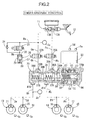
FIG. 2] FIG. 2 is a diagram of a fluid pressure circuit of the brake device for a vehicle under an abnormal condition. (first embodiment) - [
FIG. 3] FIG. 3 is a flowchart explaining operations at the time of switching from regenerative braking to fluid pressure braking. (first embodiment) - [
FIG. 4] FIG. 4 is a flowchart explaining operations at the time of switching from regenerative braking to fluid pressure braking. (second embodiment) - [
FIG. 5] FIG. 5 is a time chart explaining operations at the time of switching from regenerative braking to fluid pressure braking. (second embodiment) - [
FIG. 6] FIG. 6 is a time chart explaining operations at the time of switching from regenerative braking to fluid pressure braking. (conventional example) -
- 12
- Brake pedal
- 16
- Wheel cylinder
- 17
- Wheel cylinder
- 20
- Wheel cylinder
- 21
- Wheel cylinder
- 23
- Slave cylinder (electric brake-fluid-pressure generator)
- 52
- Electric motor
- A first embodiment of the present invention is explained below based on
FIG. 1 to FIG. 3 . - As shown in
FIG. 1 , a tandem-type master cylinder 11 includes a secondaryfluid pressure chamber 13A and a primaryfluid pressure chamber 13B for outputting a brake fluid pressure corresponding to a tread force applied to abrake pedal 12 by a driver. The secondaryfluid pressure chamber 13A is connected towheel cylinders disk brake devices fluid pressure chamber 13B is connected towheel cylinders disk brake devices - An on-off
valve 22A, which is a normally open electromagnetic valve, is disposed between the fluid paths Pa and Pb while an on-offvalve 22B, which is a normally open electromagnetic valve, is disposed between the fluid paths Qa and Qb, and aslave cylinder 23 is disposed between the fluid paths Pb and Qb and the fluid paths Pc and Qc. Moreover, astroke simulator 26 is connected to fluid paths Ra and Rb branching from the fluid path Qa leading out of the primaryfluid pressure chamber 13B, through a reactionforce allowing valve 25, which is a normally closed electromagnetic valve. Thestroke simulator 26 is formed by slidably fitting, to acylinder 27, apiston 29 biased by asimulator spring 28, and afluid pressure chamber 30 formed on the opposite side of thepiston 29 from thesimulator spring 28 communicates with the fluid path Rb. Acheck valve 24 is connected so as to allow brake fluid to flow only from thestroke simulator 26 side to themaster cylinder 11 side while bypassing the reactionforce allowing valve 25. - An
actuator 51 of theslave cylinder 23 includes: adrive bevel gear 53 provided to a rotation shaft of anelectric motor 52; afollower bevel gear 54 meshed with thedrive bevel gear 53; and aball screw mechanism 55 operated by thefollower bevel gear 54. Asleeve 58 is rotatably supported at anactuator housing 56 by a pair ofball bearings output shaft 59 is disposed coaxially on an inner periphery of thesleeve 58 while thefollower bevel gear 54 is fixed to an outer periphery of thesleeve 58. - A
secondary piston 38A and aprimary piston 38B biased in a rearward direction by a pair of return springs 37A and 37B are slidably disposed in a cylindermain body 36 of theslave cylinder 23, and a secondaryfluid pressure chamber 39A is defined in front of thesecondary piston 38A and a primaryfluid pressure chamber 39B is defined in front of theprimary piston 38B. A front end of theoutput shaft 59 is in contact with a rear end of thesecondary piston 38A. The secondaryfluid pressure chamber 39A communicates with the fluid paths Pb and Pc throughports fluid pressure chamber 39B communicates with the fluid paths Qb and Qc throughports - A fluid pressure sensor Sa for detecting a brake fluid pressure generated by the primary
fluid pressure chamber 13B of themaster cylinder 11 is provided to the fluid path Qa, and a fluid pressure sensor Sb for detecting a brake fluid pressure generated by the primaryfluid pressure chamber 39B of theslave cylinder 23 is provided to the fluid path Qc. In addition, vehicle speed sensors Sc··· for detecting a vehicle speed on the basis of the average value of outputs therefrom are provided to the wheels, respectively. Further, a current sensor Sd for detecting a current of theelectric motor 52 and a rotation angle sensor Se for detecting a rotation angle of theelectric motor 52 are provided to theelectric motor 52 of theslave cylinder 23. An unillustrated electronic control unit to which signals from the fluid pressure sensors Sa and Sb, the vehicle speed sensors Sc···, the current sensor Sd and the rotation angle sensor Se are inputted controls operations of the on-offvalves force allowing valve 25, theslave cylinder 23 and a motor generator, which is described later. - This embodiment is intended for a hybrid vehicle or an electric automobile, and can provide regenerative braking for the driving wheels when the driving wheels are connected to the motor generator as well as fluid pressure braking for the four wheels using a brake fluid pressure generated by the
slave cylinder 23. The electronic control unit provides coordination control of both the regenerative braking by the motor generator and the fluid pressure braking by theslave cylinder 23. The electronic control unit distributes a brake fluid pressure detected by the fluid pressure sensor Sa (i.e. a required braking force according to the driver) to a regenerative braking force and a fluid pressure braking force, and controls the regenerative braking force of the motor generator and the fluid pressure braking force of theslave cylinder 23 according to the distribution. - Next, descriptions will be given of operation of the fluid pressure braking by the
slave cylinder 23. - In a normal state where the system operates normally, the on-off
valves force allowing valve 25, which is a normally closed electromagnetic valve, is opened by being excited. Upon receipt of an instruction of fluid pressure braking by the electronic control unit in this state, theactuator 51 of theslave cylinder 23 starts to operate. Specifically, when theelectric motor 52 is driven in one direction, theoutput shaft 59 moves forward by the action of thedrive bevel gear 53, thefollower bevel gear 54 and theball screw mechanism 55, and thereby thesecondary piston 38A and theprimary piston 38B pushed by theoutput shaft 59 move forward. Since the on-offvalves fluid pressure chamber 39A and the primaryfluid pressure chamber 39B immediately after the twopistons wheel cylinders disk brake devices - At this time, a brake fluid pressure generated by the primary
fluid pressure chamber 13B of themaster cylinder 11 is transmitted to thefluid pressure chamber 30 of thestroke simulator 26 through the reactionforce allowing valve 25 which is opened, thereby moving thepiston 29 against thesimulator spring 28. This allows thebrake pedal 12 to stroke, and can also resolve discomfort of the driver by generating a pseudo pedal reaction force. - In addition, the operation of the
actuator 51 of theslave cylinder 23 is controlled so that the brake fluid pressure by theslave cylinder 23 detected by the fluid pressure sensor Sb provided to the fluid path Qc would correspond to a fluid pressure braking force specified by an instruction by the electronic control unit. In this way, certain braking forces can be generated for thedisk brake devices - In this embodiment, regenerative braking is given priority over fluid pressure braking. For this reason, when the regeneration efficiency of the motor generator decreases due to a decrease in the vehicle speed below a predetermined value, the regenerative braking is switched to fluid pressure braking.
- Specifically, as shown in a flowchart in
FIG. 3 , first, when the driver depresses thebrake pedal 12 to output a braking request in Step S1, it is judged in Step S2 whether or not regenerative coordination control can be performed. Specifically, when the battery is not fully charged, regenerative braking by the motor generator is possible, and theslave cylinder 23 can operate normally, it is judged in Step S2 that regenerative cooperative control can be performed, and then regenerative cooperative control is performed in Step S3. - In an initial stage of the regenerative coordination control, only regenerative braking is performed as described above so as to efficiently collect the kinetic energy of the vehicle body. Accordingly, the
slave cylinder 23 is kept in a non-operating state and hence does not generate any brake fluid pressure. Then, if it is judged in Step S4 that only regenerative braking is being performed, preparation is made in Step S5 to Step S11 for the time when the regenerative braking is to be switched to fluid pressure braking due to a decrease of the vehicle speed detected by the vehicle speed sensors Sc··· below a switching-start vehicle speed. - Specifically, on the basis of an instruction from the electronic control unit, the
electric motor 52 of theslave cylinder 23 is driven slightly, to move thesecondary piston 38A and theprimary piston 38B by the amount of an ineffective stroke in advance. An ineffective stroke is a stroke generating no brake fluid pressure in the secondaryfluid pressure chamber 39A and the primaryfluid pressure chamber 39B even when thesecondary piston 38A and theprimary piston 38B are caused to stroke by driving theelectric motor 52 of theslave cylinder 23, due to deformation of cup seals of theslave cylinder 23, deformation of cup seals of thewheel cylinders - To be more precise, first, a certain current is supplied to the
electric motor 52 according to an instruction from the electronic control unit U in Step S5, and the electronic control unit U is provided with a feedback of a current detected by the current sensor Sd in return. By driving theelectric motor 52 with a constant current in this way, a driving force corresponding to a load occurring to drive theslave cylinder 23 can be generated in theelectric motor 52 without fail. - Subsequently, in Step S6, an increase rate of the brake fluid pressure (an increase amount of the brake fluid pressure per unit time) detected by the fluid pressure sensor Sb at the time of starting to supply power to the
electric motor 52 is calculated. If it is judged in Step S7 that the increase rate of the brake fluid pressure is below a predetermined value, a setting time for supplying power to theelectric motor 52 is increased in Step S8. If it is judged that the increase rate of the brake fluid pressure is equal to or above the predetermined value, on the other hand, the setting time for supplying the power to theelectric motor 52 is decreased in Step S9, and, when the setting time for power supply has elapsed in Step S10, the power supply to theelectric motor 52 is stopped in Step S11. In this way, theelectric motor 52 is operated exactly as needed, which reliably cancels out an ineffective stroke from occurring. - In another method of controlling the
electric motor 52, a current supplied to theelectric motor 52 may be gradually increased until the rotation angle of theelectric motor 52 detected by the rotation angle sensor Se reaches a rotation angle corresponding to an ineffective stroke. Employing this method can prevent a drastic operation of theelectric motor 52 and a noise generated by such an operation, and can also reduce influences of variations in voltage from power supply, temperature changes, aged deterioration of theelectric motor 52 and the like. Further, theelectric motor 52 is operated exactly as needed, which reliably prevents an ineffective stroke from occurring. - As a result, the
slave cylinder 23 can generate a brake fluid pressure immediately after being caused to operate to switch from the regenerative braking to fluid pressure braking due to a decrease of the vehicle speed below the switching-start vehicle speed. This prevents the drop of the brake fluid pressure described with reference toFIG. 6 , and keeps the sum of the regenerative braking force and the fluid pressure braking force to be precisely equal to the required braking force, which prevents deterioration of brake feeling due to a drop of braking force. - Meanwhile, when the
slave cylinder 23 becomes inoperable because of loss of power or the like, braking is performed by using a brake fluid pressure generated by themaster cylinder 11, instead of the brake fluid pressure generated by theslave cylinder 23. In this case, the regenerative braking by the motor generator is stopped, and the whole of the braking force is covered by the braking fluid pressure generated by themaster cylinder 11. - Specifically, when the power is lost, the on-off
valve force allowing valve 25, which is a normally closed electromagnetic valve, is automatically closed, as shown inFIG. 2 . In this state, brake fluid pressures generated in the secondaryfluid pressure chamber 13A and the primaryfluid pressure chamber 13B of the master cylinder cause thewheel cylinders disk brake devices fluid pressure chamber 39A and the primaryfluid pressure chamber 39B of theslave cylinder 23 without being absorbed by thestroke simulator 26, thereby generating a braking force without any problem. - If the power is lost in the state where a brake fluid let out from the secondary
fluid pressure chamber 13A of themaster cylinder 11 when the driver depresses thebrake pedal 12 is absorbed by thestroke simulator 26, the reactionforce allowing valve 25, which is a normally closed electromagnetic valve, is automatically closed, and thereby the brake fluid is trapped in thefluid pressure chamber 30 of thestroke simulator 26. The brake fluid thus trapped is sent back to themaster cylinder 11 side through thecheck valve 24, thus preventing shift in position of thebrake pedal 12 because of a lack of the brake fluid. - Next, a second embodiment of the present invention will be described below based on
FIG. 4 andFIG. 5 . - In the first embodiment, every time regenerative braking is performed, the
slave cylinder 23 is driven to cancel out an ineffective stroke. However, if the driver lets thebrake pedal 12 off before the vehicle speed decreases below the switching-start vehicle speed, fluid pressure braking by theslave cylinder 23 ends up with not being performed. In this case, the drive of theslave cylinder 23 canceling out an ineffective stroke may be in vain. - A flowchart of the second embodiment shown in
FIG. 4 is a solution of the above-described problem, and Step S4A is added to a position after Step S4 in the flowchart inFIG. 3 showing the control according to the first embodiment. Specifically, when it is judged in Step S4 that only the regenerative braking is being performed, and it is judged that the vehicle speed detected by the vehicle speed sensors Sc··· is below a switching-preparation-start vehicle speed, which is slightly higher than the above-described switching-start vehicle speed, preparation is made in Step S5 to Step S11 by driving theslave cylinder 23 to cancel out an ineffective stroke, for the time when the regenerative braking is to be switched to fluid pressure braking due to a decrease of the vehicle speed below the switching-start vehicle speed. - According to this embodiment, even when regenerative braking is being performed, the
slave cylinder 23 is not driven to cancel out an ineffective stroke, until the vehicle speed is decreased below the switching-preparation-start vehicle speed, which is slightly higher than the switching-start vehicle speed. Accordingly, it is possible to prevent, if the driver lets thebrake pedal 12 off, theslave cylinder 23 from being driven unnecessarily so as to cancel out an ineffective stroke. - This operation will be further described with reference to a time chart in
FIG. 5 . - When the driver depresses the
brake pedal 12 at Time t0, a full regenerative braking mode starts. A required braking force increases from 0 to a predetermined value until Time t1, and then regenerative braking starts, thereby increasing also deceleration from 0 to a predetermined value. When the vehicle speed is decreased below the switching-preparation-start vehicle speed at Time t2, a fluid-pressure-braking-preparation flag is set, and theslave cylinder 23 is operated slightly so as to cancel out an ineffective stroke. Then, when the vehicle speed is decreased below the switching-start vehicle speed at Time t3, the full regenerative braking mode is switched to a switching mode. Then, the regenerative braking force is decreased toward 0 until Time t4, and at the same time, theslave cylinder 23 starts to operate to increase a fluid pressure braking force from 0 to a predetermined value. - In this operation, since the
slave cylinder 23 operates in advance at Time t2 to cancel out an ineffective stroke, the brake fluid pressure increases immediately after theslave cylinder 23 starts to operate officially at Time t3, which can make the total braking force of the regenerative braking force and the fluid braking force equal to the required braking force. Accordingly, a drop of the braking force during switching can be prevented, and hence brake feeling can be enhanced. - When the vehicle speed is decreased below a regeneration-end vehicle speed at Time t4, the switching mode is switched to a full fluid pressure braking mode. In this mode, the brake fluid pressure generated by the
slave cylinder 23 is kept at a constant value, the regenerative braking is terminated, and the whole of the required braking force is provided by the fluid pressure braking. When the vehicle speed is decreased to 0 at Time t5, the full fluid pressure braking mode is switched to a non-braking mode, and the deceleration of the vehicle body is decreased to 0. - Embodiments of the present invention have been described above, but various design modifications can be made to the present invention without departing from the gist thereof.
- For example, in the embodiments, the
slave cylinder 23 is provided as an example of an electric brake-fluid-pressure generator. However, the electric brake-fluid-pressure generator can have any configuration as long as being for generating a brake fluid pressure electrically. - Moreover, in the embodiments, the
wheel cylinders slave cylinder 23. However, a VSA (vehicle stability assist) system or an ABS (anti-lock brake system) may be provided therebetween.
Claims (6)
- A brake device for a vehicle capable of regenerative braking and fluid pressure braking, including an electric brake-fluid-pressure generator for generating a brake fluid pressure for the fluid pressure braking,
characterized in that
the electric brake-fluid-pressure generator is caused to operate to cancel out an ineffective stroke in the fluid pressure braking before switching from the regenerative braking to the fluid pressure braking. - The brake device for a vehicle according to claim 1, wherein the ineffective stroke is cancelled out when it is detected that the regenerative braking is being performed.
- The brake device for a vehicle according to claim 1, wherein the ineffective stroke is cancelled out when it is detected that a vehicle speed is decreased below a predetermined value while the regenerative braking is being performed.
- The brake device for a vehicle according to any one of claims 1 to 3, wherein the electric brake-fluid-pressure generator cancels out the ineffective stroke by supplying a constant current to an electric motor.
- The brake device for a vehicle according to any one of claims 1 to 3, wherein the electric brake-fluid-pressure generator cancels out the ineffective stroke by gradually increasing a current supplied to an electric motor until an operation amount of the electric motor reaches a predetermined value.
- The brake device for a vehicle according to claim 4 or 5, wherein the electric brake-fluid-pressure generator determines an operation amount of the electric motor necessary to cancel out the ineffective stroke, on the basis of variation of a brake fluid pressure in association with an operation of the electric motor.
Applications Claiming Priority (2)
| Application Number | Priority Date | Filing Date | Title |
|---|---|---|---|
| JP2009093575 | 2009-04-08 | ||
| PCT/JP2010/054569 WO2010116873A1 (en) | 2009-04-08 | 2010-03-17 | Brake device for vehicle |
Publications (3)
| Publication Number | Publication Date |
|---|---|
| EP2418132A1 true EP2418132A1 (en) | 2012-02-15 |
| EP2418132A4 EP2418132A4 (en) | 2012-10-10 |
| EP2418132B1 EP2418132B1 (en) | 2013-12-11 |
Family
ID=42936160
Family Applications (1)
| Application Number | Title | Priority Date | Filing Date |
|---|---|---|---|
| EP10761574.2A Not-in-force EP2418132B1 (en) | 2009-04-08 | 2010-03-17 | Brake device for vehicle |
Country Status (5)
| Country | Link |
|---|---|
| US (1) | US8794719B2 (en) |
| EP (1) | EP2418132B1 (en) |
| JP (1) | JP5497742B2 (en) |
| CN (1) | CN102361786B (en) |
| WO (1) | WO2010116873A1 (en) |
Cited By (1)
| Publication number | Priority date | Publication date | Assignee | Title |
|---|---|---|---|---|
| WO2016146277A1 (en) * | 2015-03-18 | 2016-09-22 | Robert Bosch Gmbh | Method for operating a recuperative brake system of a vehicle and control device for a recuperative brake system of a vehicle |
Families Citing this family (14)
| Publication number | Priority date | Publication date | Assignee | Title |
|---|---|---|---|---|
| GB2483477B (en) * | 2010-09-09 | 2013-07-24 | Lightning Car Company Ltd | Braking |
| JP5797542B2 (en) * | 2011-12-20 | 2015-10-21 | 日立オートモティブシステムズ株式会社 | Brake device |
| JP6024333B2 (en) * | 2012-09-21 | 2016-11-16 | 日産自動車株式会社 | Brake control device for vehicle |
| FR3002508B1 (en) * | 2013-02-25 | 2016-07-29 | Commissariat Energie Atomique | BRAKING SYSTEM OF A VEHICLE |
| JP5979101B2 (en) * | 2013-08-26 | 2016-08-24 | トヨタ自動車株式会社 | vehicle |
| JP2015074369A (en) * | 2013-10-10 | 2015-04-20 | 日産自動車株式会社 | Longitudinal acceleration control device |
| JP6595417B2 (en) * | 2016-08-10 | 2019-10-23 | 株式会社アドヴィックス | Braking device for vehicle |
| KR102347687B1 (en) * | 2017-02-20 | 2022-01-05 | 현대자동차주식회사 | Method for controlling brake system to prevent braking inconvenience in automatic driving |
| CN107310557B (en) * | 2017-07-05 | 2019-08-02 | 重庆大学 | A Coordinated Control Method for Braking Mode Switching of Hybrid Electric Vehicles |
| CN112848907B (en) * | 2019-11-12 | 2022-09-30 | 广州汽车集团股份有限公司 | Vehicle brake control method and device |
| JP7481152B2 (en) * | 2020-04-12 | 2024-05-10 | 株式会社Subaru | Vehicle Control Systems |
| JP7727568B2 (en) * | 2022-02-14 | 2025-08-21 | 株式会社Subaru | Vehicle control device |
| JP7826726B2 (en) * | 2022-02-16 | 2026-03-10 | 株式会社アドヴィックス | Braking control device |
| JP2024170192A (en) * | 2023-05-26 | 2024-12-06 | 株式会社アドヴィックス | Vehicle Brake Device |
Family Cites Families (14)
| Publication number | Priority date | Publication date | Assignee | Title |
|---|---|---|---|---|
| JPH06153316A (en) * | 1992-11-13 | 1994-05-31 | Honda Motor Co Ltd | Brake system for motor vehicle |
| JPH07264710A (en) * | 1994-03-17 | 1995-10-13 | Honda Motor Co Ltd | Braking device for electric vehicle |
| JP3565353B2 (en) | 1994-07-13 | 2004-09-15 | 株式会社ボッシュオートモーティブシステム | Regenerative brake interlocking friction brake system |
| JP2000225932A (en) | 1999-02-04 | 2000-08-15 | Toyota Motor Corp | Electric vehicle braking control device |
| JP3939482B2 (en) | 2000-01-21 | 2007-07-04 | 住友電工ブレーキシステムズ株式会社 | Braking torque control device |
| JP4370775B2 (en) | 2002-12-17 | 2009-11-25 | 日産自動車株式会社 | Combined brake coordination controller |
| DE102004027256A1 (en) | 2003-06-05 | 2005-01-05 | Continental Teves Ag & Co. Ohg | Motor vehicle brake system has electric regenerative brake, especially generator, hydraulic friction brakes driven by hydraulic system with brake arrangement, low-pressure brake fluid storage devices |
| JP2005329740A (en) * | 2004-05-18 | 2005-12-02 | Toyota Motor Corp | Vehicle braking system |
| JP4296991B2 (en) | 2004-06-08 | 2009-07-15 | 株式会社アドヴィックス | Brake device for vehicle |
| US20050269875A1 (en) | 2004-06-08 | 2005-12-08 | Kazuya Maki | Vehicle brake device |
| JP4449781B2 (en) * | 2005-02-25 | 2010-04-14 | トヨタ自動車株式会社 | Braking control device |
| JP2006312384A (en) * | 2005-05-09 | 2006-11-16 | Honda Motor Co Ltd | Vehicle regenerative braking and friction braking device |
| US8366210B2 (en) * | 2006-04-03 | 2013-02-05 | Advics Co., Ltd. | Braking apparatus for vehicle |
| JP4717779B2 (en) * | 2006-10-30 | 2011-07-06 | 本田技研工業株式会社 | Brake device |
-
2010
- 2010-03-17 CN CN201080013447.2A patent/CN102361786B/en not_active Expired - Fee Related
- 2010-03-17 WO PCT/JP2010/054569 patent/WO2010116873A1/en not_active Ceased
- 2010-03-17 JP JP2011508311A patent/JP5497742B2/en not_active Expired - Fee Related
- 2010-03-17 US US13/258,525 patent/US8794719B2/en not_active Expired - Fee Related
- 2010-03-17 EP EP10761574.2A patent/EP2418132B1/en not_active Not-in-force
Cited By (3)
| Publication number | Priority date | Publication date | Assignee | Title |
|---|---|---|---|---|
| WO2016146277A1 (en) * | 2015-03-18 | 2016-09-22 | Robert Bosch Gmbh | Method for operating a recuperative brake system of a vehicle and control device for a recuperative brake system of a vehicle |
| JP2018509334A (en) * | 2015-03-18 | 2018-04-05 | ローベルト ボッシュ ゲゼルシャフト ミット ベシュレンクテル ハフツング | Method for operating a regenerative braking system for a vehicle and a control device for a regenerative braking system for a vehicle |
| US11110802B2 (en) | 2015-03-18 | 2021-09-07 | Robert Bosch Gmbh | Method for operating a regenerative braking system of a vehicle and control unit for a regenerative braking system of a vehicle |
Also Published As
| Publication number | Publication date |
|---|---|
| US20120007417A1 (en) | 2012-01-12 |
| WO2010116873A1 (en) | 2010-10-14 |
| JPWO2010116873A1 (en) | 2012-10-18 |
| CN102361786A (en) | 2012-02-22 |
| JP5497742B2 (en) | 2014-05-21 |
| EP2418132B1 (en) | 2013-12-11 |
| US8794719B2 (en) | 2014-08-05 |
| EP2418132A4 (en) | 2012-10-10 |
| CN102361786B (en) | 2014-03-19 |
Similar Documents
| Publication | Publication Date | Title |
|---|---|---|
| EP2418132B1 (en) | Brake device for vehicle | |
| EP2428416B1 (en) | Vehicle braking device | |
| JP5351256B2 (en) | Brake device for automobile, operation method thereof and hydraulic device | |
| JP5514805B2 (en) | Brake control device | |
| JP6219186B2 (en) | Brake control device | |
| KR102480768B1 (en) | Method for operating regenerative brake system of vehicle, and control device for regenerative brake system of vehicle | |
| US9586486B2 (en) | Control unit for a recuperative brake system of a vehicle and method for braking a vehicle | |
| JP5961513B2 (en) | Vehicle control device and brake control device | |
| JP5863954B2 (en) | CONTROL DEVICE FOR VEHICLE BRAKE SYSTEM AND METHOD FOR OPERATING VEHICLE BRAKE SYSTEM | |
| US10005442B2 (en) | Brake control device | |
| JP2014051285A (en) | Brake device of automobile, hydraulic device therefor, and operation method of brake device | |
| KR20130140040A (en) | Control device and method for operating a braking system equipped with an electrical drive device and/or generator device | |
| CN103702874A (en) | Control device for brake system of vehicle, brake system for vehicle and method for operating brake system of vehicle | |
| KR20110101154A (en) | Vehicle brake system and control method of the brake system | |
| AU2014313900A1 (en) | Vehicle | |
| JP5566873B2 (en) | Brake device for vehicle | |
| JP2014069756A (en) | Brake control device | |
| JP2015030426A (en) | Braking device for vehicle | |
| KR102487781B1 (en) | Regenerative braking system for a vehicle and method for operating the regenerative braking system in a vehicle | |
| JP5113535B2 (en) | Brake device |
Legal Events
| Date | Code | Title | Description |
|---|---|---|---|
| PUAI | Public reference made under article 153(3) epc to a published international application that has entered the european phase |
Free format text: ORIGINAL CODE: 0009012 |
|
| 17P | Request for examination filed |
Effective date: 20111028 |
|
| AK | Designated contracting states |
Kind code of ref document: A1 Designated state(s): AT BE BG CH CY CZ DE DK EE ES FI FR GB GR HR HU IE IS IT LI LT LU LV MC MK MT NL NO PL PT RO SE SI SK SM TR |
|
| DAX | Request for extension of the european patent (deleted) | ||
| A4 | Supplementary search report drawn up and despatched |
Effective date: 20120906 |
|
| RIC1 | Information provided on ipc code assigned before grant |
Ipc: B60T 8/00 20060101AFI20120831BHEP Ipc: B60L 7/24 20060101ALI20120831BHEP Ipc: B60T 8/17 20060101ALI20120831BHEP Ipc: B60L 7/10 20060101ALI20120831BHEP |
|
| 17Q | First examination report despatched |
Effective date: 20120918 |
|
| GRAP | Despatch of communication of intention to grant a patent |
Free format text: ORIGINAL CODE: EPIDOSNIGR1 |
|
| INTG | Intention to grant announced |
Effective date: 20130702 |
|
| GRAS | Grant fee paid |
Free format text: ORIGINAL CODE: EPIDOSNIGR3 |
|
| GRAA | (expected) grant |
Free format text: ORIGINAL CODE: 0009210 |
|
| AK | Designated contracting states |
Kind code of ref document: B1 Designated state(s): AT BE BG CH CY CZ DE DK EE ES FI FR GB GR HR HU IE IS IT LI LT LU LV MC MK MT NL NO PL PT RO SE SI SK SM TR |
|
| REG | Reference to a national code |
Ref country code: GB Ref legal event code: FG4D |
|
| REG | Reference to a national code |
Ref country code: CH Ref legal event code: EP |
|
| REG | Reference to a national code |
Ref country code: AT Ref legal event code: REF Ref document number: 644362 Country of ref document: AT Kind code of ref document: T Effective date: 20140115 |
|
| REG | Reference to a national code |
Ref country code: IE Ref legal event code: FG4D |
|
| REG | Reference to a national code |
Ref country code: DE Ref legal event code: R096 Ref document number: 602010012381 Country of ref document: DE Effective date: 20140206 |
|
| REG | Reference to a national code |
Ref country code: NL Ref legal event code: VDEP Effective date: 20131211 |
|
| REG | Reference to a national code |
Ref country code: AT Ref legal event code: MK05 Ref document number: 644362 Country of ref document: AT Kind code of ref document: T Effective date: 20131211 |
|
| PG25 | Lapsed in a contracting state [announced via postgrant information from national office to epo] |
Ref country code: LT Free format text: LAPSE BECAUSE OF FAILURE TO SUBMIT A TRANSLATION OF THE DESCRIPTION OR TO PAY THE FEE WITHIN THE PRESCRIBED TIME-LIMIT Effective date: 20131211 Ref country code: SE Free format text: LAPSE BECAUSE OF FAILURE TO SUBMIT A TRANSLATION OF THE DESCRIPTION OR TO PAY THE FEE WITHIN THE PRESCRIBED TIME-LIMIT Effective date: 20131211 Ref country code: HR Free format text: LAPSE BECAUSE OF FAILURE TO SUBMIT A TRANSLATION OF THE DESCRIPTION OR TO PAY THE FEE WITHIN THE PRESCRIBED TIME-LIMIT Effective date: 20131211 Ref country code: NL Free format text: LAPSE BECAUSE OF FAILURE TO SUBMIT A TRANSLATION OF THE DESCRIPTION OR TO PAY THE FEE WITHIN THE PRESCRIBED TIME-LIMIT Effective date: 20131211 Ref country code: FI Free format text: LAPSE BECAUSE OF FAILURE TO SUBMIT A TRANSLATION OF THE DESCRIPTION OR TO PAY THE FEE WITHIN THE PRESCRIBED TIME-LIMIT Effective date: 20131211 Ref country code: NO Free format text: LAPSE BECAUSE OF FAILURE TO SUBMIT A TRANSLATION OF THE DESCRIPTION OR TO PAY THE FEE WITHIN THE PRESCRIBED TIME-LIMIT Effective date: 20140311 |
|
| REG | Reference to a national code |
Ref country code: LT Ref legal event code: MG4D |
|
| PG25 | Lapsed in a contracting state [announced via postgrant information from national office to epo] |
Ref country code: CY Free format text: LAPSE BECAUSE OF FAILURE TO SUBMIT A TRANSLATION OF THE DESCRIPTION OR TO PAY THE FEE WITHIN THE PRESCRIBED TIME-LIMIT Effective date: 20131211 Ref country code: LV Free format text: LAPSE BECAUSE OF FAILURE TO SUBMIT A TRANSLATION OF THE DESCRIPTION OR TO PAY THE FEE WITHIN THE PRESCRIBED TIME-LIMIT Effective date: 20131211 Ref country code: AT Free format text: LAPSE BECAUSE OF FAILURE TO SUBMIT A TRANSLATION OF THE DESCRIPTION OR TO PAY THE FEE WITHIN THE PRESCRIBED TIME-LIMIT Effective date: 20131211 |
|
| PG25 | Lapsed in a contracting state [announced via postgrant information from national office to epo] |
Ref country code: IS Free format text: LAPSE BECAUSE OF FAILURE TO SUBMIT A TRANSLATION OF THE DESCRIPTION OR TO PAY THE FEE WITHIN THE PRESCRIBED TIME-LIMIT Effective date: 20140411 Ref country code: BE Free format text: LAPSE BECAUSE OF FAILURE TO SUBMIT A TRANSLATION OF THE DESCRIPTION OR TO PAY THE FEE WITHIN THE PRESCRIBED TIME-LIMIT Effective date: 20131211 Ref country code: EE Free format text: LAPSE BECAUSE OF FAILURE TO SUBMIT A TRANSLATION OF THE DESCRIPTION OR TO PAY THE FEE WITHIN THE PRESCRIBED TIME-LIMIT Effective date: 20131211 |
|
| PG25 | Lapsed in a contracting state [announced via postgrant information from national office to epo] |
Ref country code: RO Free format text: LAPSE BECAUSE OF FAILURE TO SUBMIT A TRANSLATION OF THE DESCRIPTION OR TO PAY THE FEE WITHIN THE PRESCRIBED TIME-LIMIT Effective date: 20131211 Ref country code: PT Free format text: LAPSE BECAUSE OF FAILURE TO SUBMIT A TRANSLATION OF THE DESCRIPTION OR TO PAY THE FEE WITHIN THE PRESCRIBED TIME-LIMIT Effective date: 20140411 Ref country code: SK Free format text: LAPSE BECAUSE OF FAILURE TO SUBMIT A TRANSLATION OF THE DESCRIPTION OR TO PAY THE FEE WITHIN THE PRESCRIBED TIME-LIMIT Effective date: 20131211 Ref country code: PL Free format text: LAPSE BECAUSE OF FAILURE TO SUBMIT A TRANSLATION OF THE DESCRIPTION OR TO PAY THE FEE WITHIN THE PRESCRIBED TIME-LIMIT Effective date: 20131211 Ref country code: CZ Free format text: LAPSE BECAUSE OF FAILURE TO SUBMIT A TRANSLATION OF THE DESCRIPTION OR TO PAY THE FEE WITHIN THE PRESCRIBED TIME-LIMIT Effective date: 20131211 Ref country code: ES Free format text: LAPSE BECAUSE OF FAILURE TO SUBMIT A TRANSLATION OF THE DESCRIPTION OR TO PAY THE FEE WITHIN THE PRESCRIBED TIME-LIMIT Effective date: 20131211 |
|
| PGFP | Annual fee paid to national office [announced via postgrant information from national office to epo] |
Ref country code: GB Payment date: 20140319 Year of fee payment: 5 |
|
| REG | Reference to a national code |
Ref country code: DE Ref legal event code: R097 Ref document number: 602010012381 Country of ref document: DE |
|
| PLBE | No opposition filed within time limit |
Free format text: ORIGINAL CODE: 0009261 |
|
| STAA | Information on the status of an ep patent application or granted ep patent |
Free format text: STATUS: NO OPPOSITION FILED WITHIN TIME LIMIT |
|
| PG25 | Lapsed in a contracting state [announced via postgrant information from national office to epo] |
Ref country code: DK Free format text: LAPSE BECAUSE OF FAILURE TO SUBMIT A TRANSLATION OF THE DESCRIPTION OR TO PAY THE FEE WITHIN THE PRESCRIBED TIME-LIMIT Effective date: 20131211 Ref country code: LU Free format text: LAPSE BECAUSE OF FAILURE TO SUBMIT A TRANSLATION OF THE DESCRIPTION OR TO PAY THE FEE WITHIN THE PRESCRIBED TIME-LIMIT Effective date: 20140317 |
|
| REG | Reference to a national code |
Ref country code: CH Ref legal event code: PL |
|
| 26N | No opposition filed |
Effective date: 20140912 |
|
| REG | Reference to a national code |
Ref country code: DE Ref legal event code: R084 Ref document number: 602010012381 Country of ref document: DE |
|
| REG | Reference to a national code |
Ref country code: DE Ref legal event code: R097 Ref document number: 602010012381 Country of ref document: DE Effective date: 20140912 |
|
| REG | Reference to a national code |
Ref country code: FR Ref legal event code: ST Effective date: 20141128 |
|
| REG | Reference to a national code |
Ref country code: DE Ref legal event code: R084 Ref document number: 602010012381 Country of ref document: DE Effective date: 20141120 Ref country code: IE Ref legal event code: MM4A |
|
| PG25 | Lapsed in a contracting state [announced via postgrant information from national office to epo] |
Ref country code: IE Free format text: LAPSE BECAUSE OF NON-PAYMENT OF DUE FEES Effective date: 20140317 Ref country code: CH Free format text: LAPSE BECAUSE OF NON-PAYMENT OF DUE FEES Effective date: 20140331 Ref country code: FR Free format text: LAPSE BECAUSE OF NON-PAYMENT OF DUE FEES Effective date: 20140331 Ref country code: LI Free format text: LAPSE BECAUSE OF NON-PAYMENT OF DUE FEES Effective date: 20140331 |
|
| PG25 | Lapsed in a contracting state [announced via postgrant information from national office to epo] |
Ref country code: SI Free format text: LAPSE BECAUSE OF FAILURE TO SUBMIT A TRANSLATION OF THE DESCRIPTION OR TO PAY THE FEE WITHIN THE PRESCRIBED TIME-LIMIT Effective date: 20131211 |
|
| GBPC | Gb: european patent ceased through non-payment of renewal fee |
Effective date: 20150317 |
|
| PG25 | Lapsed in a contracting state [announced via postgrant information from national office to epo] |
Ref country code: GB Free format text: LAPSE BECAUSE OF NON-PAYMENT OF DUE FEES Effective date: 20150317 |
|
| PG25 | Lapsed in a contracting state [announced via postgrant information from national office to epo] |
Ref country code: MT Free format text: LAPSE BECAUSE OF FAILURE TO SUBMIT A TRANSLATION OF THE DESCRIPTION OR TO PAY THE FEE WITHIN THE PRESCRIBED TIME-LIMIT Effective date: 20131211 |
|
| PG25 | Lapsed in a contracting state [announced via postgrant information from national office to epo] |
Ref country code: SM Free format text: LAPSE BECAUSE OF FAILURE TO SUBMIT A TRANSLATION OF THE DESCRIPTION OR TO PAY THE FEE WITHIN THE PRESCRIBED TIME-LIMIT Effective date: 20131211 |
|
| PGFP | Annual fee paid to national office [announced via postgrant information from national office to epo] |
Ref country code: DE Payment date: 20160308 Year of fee payment: 7 |
|
| PG25 | Lapsed in a contracting state [announced via postgrant information from national office to epo] |
Ref country code: MC Free format text: LAPSE BECAUSE OF FAILURE TO SUBMIT A TRANSLATION OF THE DESCRIPTION OR TO PAY THE FEE WITHIN THE PRESCRIBED TIME-LIMIT Effective date: 20131211 |
|
| PG25 | Lapsed in a contracting state [announced via postgrant information from national office to epo] |
Ref country code: GR Free format text: LAPSE BECAUSE OF FAILURE TO SUBMIT A TRANSLATION OF THE DESCRIPTION OR TO PAY THE FEE WITHIN THE PRESCRIBED TIME-LIMIT Effective date: 20140312 Ref country code: BG Free format text: LAPSE BECAUSE OF FAILURE TO SUBMIT A TRANSLATION OF THE DESCRIPTION OR TO PAY THE FEE WITHIN THE PRESCRIBED TIME-LIMIT Effective date: 20131211 Ref country code: IT Free format text: LAPSE BECAUSE OF FAILURE TO SUBMIT A TRANSLATION OF THE DESCRIPTION OR TO PAY THE FEE WITHIN THE PRESCRIBED TIME-LIMIT Effective date: 20131211 |
|
| PG25 | Lapsed in a contracting state [announced via postgrant information from national office to epo] |
Ref country code: HU Free format text: LAPSE BECAUSE OF FAILURE TO SUBMIT A TRANSLATION OF THE DESCRIPTION OR TO PAY THE FEE WITHIN THE PRESCRIBED TIME-LIMIT; INVALID AB INITIO Effective date: 20100317 Ref country code: TR Free format text: LAPSE BECAUSE OF FAILURE TO SUBMIT A TRANSLATION OF THE DESCRIPTION OR TO PAY THE FEE WITHIN THE PRESCRIBED TIME-LIMIT Effective date: 20131211 |
|
| REG | Reference to a national code |
Ref country code: DE Ref legal event code: R119 Ref document number: 602010012381 Country of ref document: DE |
|
| PG25 | Lapsed in a contracting state [announced via postgrant information from national office to epo] |
Ref country code: DE Free format text: LAPSE BECAUSE OF NON-PAYMENT OF DUE FEES Effective date: 20171003 |
|
| PG25 | Lapsed in a contracting state [announced via postgrant information from national office to epo] |
Ref country code: MK Free format text: LAPSE BECAUSE OF FAILURE TO SUBMIT A TRANSLATION OF THE DESCRIPTION OR TO PAY THE FEE WITHIN THE PRESCRIBED TIME-LIMIT Effective date: 20131211 |