EP2418056A1 - Method for molding wood - Google Patents
Method for molding wood Download PDFInfo
- Publication number
- EP2418056A1 EP2418056A1 EP10758869A EP10758869A EP2418056A1 EP 2418056 A1 EP2418056 A1 EP 2418056A1 EP 10758869 A EP10758869 A EP 10758869A EP 10758869 A EP10758869 A EP 10758869A EP 2418056 A1 EP2418056 A1 EP 2418056A1
- Authority
- EP
- European Patent Office
- Prior art keywords
- wooden piece
- wooden
- reinforcing member
- compression
- reinforcing
- Prior art date
- Legal status (The legal status is an assumption and is not a legal conclusion. Google has not performed a legal analysis and makes no representation as to the accuracy of the status listed.)
- Withdrawn
Links
Images



Classifications
-
- B—PERFORMING OPERATIONS; TRANSPORTING
- B27—WORKING OR PRESERVING WOOD OR SIMILAR MATERIAL; NAILING OR STAPLING MACHINES IN GENERAL
- B27M—WORKING OF WOOD NOT PROVIDED FOR IN SUBCLASSES B27B - B27L; MANUFACTURE OF SPECIFIC WOODEN ARTICLES
- B27M1/00—Working of wood not provided for in subclasses B27B - B27L, e.g. by stretching
- B27M1/02—Working of wood not provided for in subclasses B27B - B27L, e.g. by stretching by compressing
-
- B—PERFORMING OPERATIONS; TRANSPORTING
- B27—WORKING OR PRESERVING WOOD OR SIMILAR MATERIAL; NAILING OR STAPLING MACHINES IN GENERAL
- B27D—WORKING VENEER OR PLYWOOD
- B27D1/00—Joining wood veneer with any material; Forming articles thereby; Preparatory processing of surfaces to be joined, e.g. scoring
- B27D1/04—Joining wood veneer with any material; Forming articles thereby; Preparatory processing of surfaces to be joined, e.g. scoring to produce plywood or articles made therefrom; Plywood sheets
- B27D1/08—Manufacture of shaped articles; Presses specially designed therefor
Definitions
- the present invention is related to a method of forming a wooden piece so that the wooden piece is formed into a predetermined three-dimensional shape by compressing the wooden piece.
- wood materials that are natural materials attract attention.
- wood products made of wood exhibit individual features depending on positions of the raw wood from which the particular wood products are cut out.
- Such individual features of each wood product give it a unique quality.
- surface flaws and discolorations caused by a long-term use create unique textures which tend to evoke warm and familiar feeling in the user.
- the wooden material attracts attention as a material for products of uniqueness and taste which cannot be found in products made of synthetic resin or light metals. Techniques for molding wooden materials are also developing dramatically.
- a wooden board is softened with water absorption and compressed; the compressed wooden board is cut along a direction substantially parallel with a direction in which the compressive force is applied, whereby a primary fixed product with a sheet-like shape is obtained; and the primary fixed product is deformed into a desired three-dimensional shape under heat and moisture (for example, see Patent Literature 1).
- a softened wooden sheet is compressed and temporarily secured in a prepared mold and left in the mold until the wooden sheet recovers.
- a wood product with a desired shape can be obtained (see, for example, Patent Literature 2).
- the present invention has been made in consideration of the foregoing and has an object to provide a method of forming a wooden piece so as to form the wooden piece with a desired strength irrespective of the pattern of the grain of the wooden piece that is cut out from the raw wood and so as to improve the yield ratio of formed pieces.
- the reinforcing member includes a plurality of fibers, the fibers being oriented in a direction that intersects with a fiber direction of the wooden piece, and the plurality of fibers is composed of a material including cellulose that is a wood fiber component.
- an elastic reinforcing member is attached to an area of the inner surface of a wooden piece that is cut out to be substantially bowl-shaped, and the area includes a point where a change in curvature before and after compression is largest and grain separation is largest; thus, it is possible to form a wooden piece with a desired strength irrespective of the state of the grain and to improve the yield ratio of formed pieces.
- FIG. 1 is a flowchart that illustrates the outline of a method of forming a wooden piece according to an embodiment of the present invention.
- a substantially bowl-shaped wooden piece is first cut out from raw wood (Step S1).
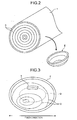
- FIG. 2 is a diagram that illustrates the outline of the cutting-out process and that schematically illustrates a state where a substantially bowl-shaped wooden piece 2 is cut out from raw wood 1.
- Step S1 a wooden piece is cut out such that the volume of the wooden piece includes an additional volume that corresponds to the volume that is lost due to the process described later.
- the raw wood 1 may be appropriately selected from hinoki cypress, hiba cedar, paulownia, Japanese cedar, pine, cherry, zelkova, ebony wood, red sandalwood, bamboo, teak, mahogany, rosewood, and the like depending on the intended use of the formed wooden piece. Part of the raw wood 1 to be cut out may be determined depending on a condition such as the strength or appearance required for the wooden piece.
- FIG. 3 is a diagram that illustrates the outline of a process for attaching a reinforcing member and is a plan view of the wooden piece 2 in Fig. 2 when viewed from above.
- a closed curve D in the form of an ellipse indicated by a broken line is the boundary area between the bottom and the rising area that are obtained after the wooden piece 2 is compressed.
- a change in curvature is largest in an area adjacent to the closed curve D.
- the separation of the grain G is largest near the middle of the upper portion of the closed curve D; therefore, there is a high possibility that this area needs reinforcement after compression rather than other areas.
- a reinforcing member 3 is attached to this area.
- the reinforcing member 3 has a similar component to a wooden piece and is composed of an elastic material. Specifically, the reinforcing member 3 is composed of a cloth or nonwoven cloth made of cotton, hemp, silk, flax, or the like that is a natural fiber that includes a wood fiber component such as cellulose or is composed of rayon, or the like that is a regenerated cellulose fiber.
- the reinforcing member 3 may be attached to the wooden piece 2 by using an adhesive agent; however, because the reinforcing member 3 and the wooden piece 2 are bonded with each other by a resin component of the wooden piece 2 after compression, it is only necessary to use an extremely small amount of adhesive agent for the attachment that is just enough to determine the position of the reinforcing member 3 with respect to the wooden piece 2.
- the shape of the reinforcing member 3 can be appropriately changed depending on the size of the area to which the reinforcing member 3 is to be attached.
- the wooden piece 2 is left for a predetermined time in a water-vapor atmosphere at a higher temperature and pressure than those in the atmospheric air so as to absorb an excessive amount of water so that the wooden piece 2 becomes softened (Step S3).
- the water vapor has a temperature of about 100 to 230°C and a pressure of about 0.1 to 3.0 MPa (megapascal).
- Such a water-vapor atmosphere can be produced by using, for example, a pressure vessel. If a pressure vessel is used, the wooden piece 2 is left in the pressure vessel so as to be softened.
- the wooden piece 2 may be softened by heating using a high-frequency electromagnetic wave, such as a microwave, after water is applied to the surface of the wooden piece 2, or the wooden piece 2 may be softened by boiling.
- a high-frequency electromagnetic wave such as a microwave
- the wooden piece 2 which has been adequately softened at Step S3, is compressed in a similar water-vapor atmosphere to that at Step S3 described above (Step S4). If the wooden piece 2 is softened in the pressure vessel, the wooden piece 2 may be continuously compressed in the pressure vessel.
- FIG. 4 is a diagram that illustrates the outline of a compression process and also illustrates the configurations of a pair of metal molds to be used in the compression process.
- a metal mold 61 is a core metal mold that applies a compressive force to the wooden piece 2 from above in FIG. 4 and that includes a protrusion 62 that can be brought into contact with the inner surface of the wooden piece 2.
- a metal mold 71 is a cavity metal mold that applies a compressive force to the wooden piece 2 from below in FIG. 4 and that includes a depression 72 that can be brought into contact with the outer surface of the wooden piece 2.
- FIG. 5 is a diagram that illustrates a state where the metal mold 61 is in contact with the wooden piece 2 and a compressive force has started to be applied to the wooden piece 2 from the metal molds 61, 71. Furthermore, FIG. 5 is a longitudinal sectional view taken along the line A-A for the wooden piece 2 and the metal molds 61, 71 illustrated in FIG. 4 .
- FIG. 6 is a diagram that illustrates a state in which there is such a close attachment and illustrates a state in which the deformation of the wooden piece 2 is almost complete in the compression process.
- the wooden piece 2 is deformed into a three-dimensional shape that corresponds to the gap between the metal mold 61 and the metal mold 71.
- a compressive force is continuously applied to the wooden piece 2, which is in the state illustrated in FIG. 6 , for a predetermined time (one to several tens of minutes, and more preferably five to ten minutes).
- the surface of the reinforcing member 3 becomes flat with respect to the surface of the wooden piece 2, and the reinforcing member 3 sinks into the wooden piece 2 (see FIG. 6 ).
- the reinforcing member 3 has similar physical properties, such as the degree of shrinkage expressed using a linear expansion coefficient, to the wooden piece; therefore, the reinforcing member 3 has a high affinity to the wooden piece.
- the reinforcing member 3 does not damage, for example, cut the fibers of the wooden piece 2, and the reinforcing member 3 is fixed to the surface of the wooden piece 2 in a state where it fits into the wooden piece 2.
- Step S5 water vapor at a higher temperature than the above-described waver vapor is applied to the surroundings of the metal molds 61, 71 while the clamped state of the metal molds 61, 71 is maintained so that the shape of the wooden piece 2 is fixed. If the fixing process is performed in the pressure vessel, water vapor at a higher temperature than that in the compression process may be brought into the pressure vessel.
- the metal molds 61, 71 and the wooden piece 2 are exposed to the atmospheric air so that the wooden piece 2 is dried (Step S6).
- the clamped state of the metal molds 61, 71 may be released to separate the metal mold 61 or 71 from the wooden piece 2 so as to facilitate drying of the wooden piece 2.
- the thickness of the wooden piece 2 is about 30 to 50% of the thickness of the wooden piece 2 that is obtained before the compression. This corresponds to the compression rate of the wooden piece 2 being about 0.50 to 0.70.
- the wooden piece 2 for which the drying process has been completed is referred to as a "wooden piece 4".
- Step S6 a process for cutting edge surfaces, or the like is performed on the wooden piece 4 so that the wooden piece 4 is formed into a predetermined shape (Step S7).
- FIG. 7 is a perspective view that illustrates the configuration of a wooden piece formed by the above-described method of forming a wooden piece.
- the wooden piece 4 illustrated in the same figure includes a main plate portion 4a that has a flat-plate shape with a substantially rectangular surface; two side plate portions 4b that each extend as if rising up with respect to the main plate portion 4a from two sides that are substantially parallel to the longitudinal direction of the surface of the main plate portion 4a; and two side plate portions 4c that each extend as if rising up with respect to the main plate portion 4a from two sides that are substantially parallel to the transverse direction of the surface of the main plate portion 4a.
- the edge surfaces of the side plate portions 4b, 4c are connected to each other, and these edge surfaces create a complete loop so as to form a closed rectangle.
- the thickness of the wooden piece 4 is almost uniform.
- FIG. 8 is a perspective view that illustrates the configuration of a digital camera whose exterior cover is partially made of the wooden piece 4.
- a digital camera 100 illustrated in the same figure includes an exterior cover 101, an imaging unit 102, a flash 103, and a shutter button 104.
- the front surface of the exterior cover 101 is obtained by forming, on the wooden piece 4, an opening through which the imaging unit 102 and the flash 103 are exposed and a cutout through which part of the flash 103 is exposed.
- the rear surface of the digital camera 100 is covered by a wooden piece 5 that is formed by using the wooden piece 2 in the same manner as the wooden piece 4. Because the grain of the wooden piece 5 is different from that of the wooden piece 4, the reinforcing member 3 is attached to a different area. It is preferable that the thickness of the wooden pieces 4 and 5 that form the exterior cover 101 be about 0.8 to 2.0 mm.
- the outer surface of the wooden piece 2 becomes the front surface of the exterior cover 101; therefore, the reinforcing member 3 attached to the inner surface of the wooden piece 2 is hidden on the back surface. Thus, the attachment of the reinforcing member 3 does not spoil the external appearance of the exterior cover 101.
- the wooden piece 4 can be used as an exterior cover of an electronic device other than a digital camera.
- an elastic reinforcing member is attached to an area of the inner surface of a wooden piece that is cut out top be substantially bowl-shaped, and the area includes a point where a change in curvature before and after compression is largest and grain separation is largest; thus, it is possible to form a wooden piece with a desired strength irrespective of the state of the grain and to improve the yield ratio of formed pieces.
- FIG. 9 is a diagram that illustrates the outline of a process for attaching a reinforcing member in a method of forming a wooden piece according to another embodiment of the present invention.
- a wooden piece B illustrated in FIG. 9 has the same shape (the substantially bowl shape) as that of the above-described wooden piece 2, the pattern of the grain G is different.
- the area with the largest separation of the grain G in the elliptical closed curve D is located near the top end and the right end illustrated in the figure.
- the reinforcing members 3 are attached to both areas. Conversely, in FIG.
- the reinforcing member 3 is attached to, out of the two areas that have almost the same separation of the grain G, only the middle portion on the right side that has a larger degree of bentness of fibers of the wooden piece before and after compression.
- the amount of the reinforcing member 3 it is possible to keep the amount of the reinforcing member 3 to be used to a minimum by considering the fiber direction of a wooden piece and a deformed state of a wooden piece before and after compression.
Landscapes
- Engineering & Computer Science (AREA)
- Life Sciences & Earth Sciences (AREA)
- Mechanical Engineering (AREA)
- Wood Science & Technology (AREA)
- Forests & Forestry (AREA)
- Manufacturing & Machinery (AREA)
- Chemical And Physical Treatments For Wood And The Like (AREA)
Abstract
Description
- The present invention is related to a method of forming a wooden piece so that the wooden piece is formed into a predetermined three-dimensional shape by compressing the wooden piece.
- In recent years, wooden materials that are natural materials attract attention. With a wide variety of grain patterns, wood products made of wood exhibit individual features depending on positions of the raw wood from which the particular wood products are cut out. Such individual features of each wood product give it a unique quality. In addition, surface flaws and discolorations caused by a long-term use create unique textures which tend to evoke warm and familiar feeling in the user. Thus, the wooden material attracts attention as a material for products of uniqueness and taste which cannot be found in products made of synthetic resin or light metals. Techniques for molding wooden materials are also developing dramatically.
- According to one conventionally known technique for molding wooden materials: a wooden board is softened with water absorption and compressed; the compressed wooden board is cut along a direction substantially parallel with a direction in which the compressive force is applied, whereby a primary fixed product with a sheet-like shape is obtained; and the primary fixed product is deformed into a desired three-dimensional shape under heat and moisture (for example, see Patent Literature 1). Further, according to another conventional technique, a softened wooden sheet is compressed and temporarily secured in a prepared mold and left in the mold until the wooden sheet recovers. Thus a wood product with a desired shape can be obtained (see, for example, Patent Literature 2).
-
- Patent Literature 1: Japanese Patent No.
3078452 - Patent Literature 2: Japanese Laid-open Patent Publication No.
11-77619 - Because of individual differences between the wooden pieces described above, even if a wooden piece with the same shape is cut out from raw wood and is molded by compression, the desired strength may not be obtained in some parts of the wooden piece depending on how a wood component moves when the wooden piece is deformed by compression. In such a case, a defect such as a crack often occurs in an area with low strength; however, because reinforcement cannot be performed after compression, there is no choice but to dispose of a wooden piece, which is an obstacle to the improvement of the yield ratio of molded pieces.
- The present invention has been made in consideration of the foregoing and has an object to provide a method of forming a wooden piece so as to form the wooden piece with a desired strength irrespective of the pattern of the grain of the wooden piece that is cut out from the raw wood and so as to improve the yield ratio of formed pieces.
- To solve the problems as described above and achieve the objet, a method of forming a wooden piece according to an aspect of the present invention is a method of forming a wooden piece so that the wooden piece is formed into a predetermined three-dimensional shape by compressing the wooden piece, and includes a reinforcing-member attachment step of attaching an elastic reinforcing member to an area of an inner surface of a wooden piece that is cut out to be substantially bowl-shaped, the area including a point where a change in curvature before and after compression is largest and separation of grain is largest; a softening step of softening the wooden piece to which the reinforcing member is attached at the reinforcing-member attachment step in a water-vapor atmosphere at a higher temperature and pressure than those in an atmospheric air; and a compression step of compressing the wooden piece that is softened at the softening step in the water-vapor atmosphere so as to deform the wooden piece into a predetermined three-dimensional shape.
- In the method of forming a wooden piece according to the present invention, the reinforcing-member attachment step includes, if there are areas on the inner surface of the wooden piece where changes in curvature before and after compression are largest and separation of the grain is largest, attaching the reinforcing member to an area that includes a point where a fiber is most bent due to the compression step.
- In the method of forming a wooden piece according to the present invention, the reinforcing member includes a plurality of fibers, the fibers being oriented in a direction that intersects with a fiber direction of the wooden piece, and the plurality of fibers is composed of a material including cellulose that is a wood fiber component. Advantageous Effects of Invention
- According to the present invention, an elastic reinforcing member is attached to an area of the inner surface of a wooden piece that is cut out to be substantially bowl-shaped, and the area includes a point where a change in curvature before and after compression is largest and grain separation is largest; thus, it is possible to form a wooden piece with a desired strength irrespective of the state of the grain and to improve the yield ratio of formed pieces.
-
-
FIG. 1 is a flowchart that illustrates the outline of a process in a method of forming a wooden piece according to an embodiment of the present invention. -
FIG. 2 is a diagram that illustrates the outline of a cutting-out process in the method of forming a wooden piece according to the embodiment of the present invention. -
FIG. 3 is a diagram that illustrates the outline of a process for attaching a reinforcing member in the method of forming a wooden piece according to the embodiment of the present invention. -
FIG. 4 is a diagram that illustrates the outline of a compression process in the method of forming a wooden piece according to the embodiment of the present invention. -
FIG. 5 is a diagram that illustrates a state where compression has started in the compression process. -
FIG. 6 is a diagram that illustrates a state in which the deformation of a wooden piece is almost complete in the compression process. -
FIG. 7 is a perspective view that illustrates the configuration of a wooden piece that is obtained after compression forming. -
FIG. 8 is a perspective view that illustrates the exterior configuration of a digital camera as an example of the application of a wooden piece formed by using the method of forming a wooden piece according to the embodiment of the present invention. -
FIG. 9 is a diagram that illustrates the outline of a process for attaching a reinforcing member in a method of forming a wooden piece according to another embodiment of the present invention. - An explanation is given of preferred embodiments (hereinafter, referred to as "embodiments") of the present invention with reference to the accompanying drawings. The drawings that are referred to in the following descriptions are schematically illustrated. When the same object is illustrated in a different drawing, its dimension, scale, or the like may be different.
-
FIG. 1 is a flowchart that illustrates the outline of a method of forming a wooden piece according to an embodiment of the present invention. In the method of forming a wooden piece according to the first embodiment, a substantially bowl-shaped wooden piece is first cut out from raw wood (Step S1).FIG. 2 is a diagram that illustrates the outline of the cutting-out process and that schematically illustrates a state where a substantially bowl-shapedwooden piece 2 is cut out fromraw wood 1. At Step S1, a wooden piece is cut out such that the volume of the wooden piece includes an additional volume that corresponds to the volume that is lost due to the process described later. Theraw wood 1 may be appropriately selected from hinoki cypress, hiba cedar, paulownia, Japanese cedar, pine, cherry, zelkova, ebony wood, red sandalwood, bamboo, teak, mahogany, rosewood, and the like depending on the intended use of the formed wooden piece. Part of theraw wood 1 to be cut out may be determined depending on a condition such as the strength or appearance required for the wooden piece. - Next, a reinforcing member is attached to the wooden piece 2 (Step S2).
FIG. 3 is a diagram that illustrates the outline of a process for attaching a reinforcing member and is a plan view of thewooden piece 2 inFig. 2 when viewed from above. InFIG. 3 , a closed curve D in the form of an ellipse indicated by a broken line is the boundary area between the bottom and the rising area that are obtained after thewooden piece 2 is compressed. Specifically, with respect to thewooden piece 2, a change in curvature is largest in an area adjacent to the closed curve D. In the case illustrated inFIG. 3 , the separation of the grain G is largest near the middle of the upper portion of the closed curve D; therefore, there is a high possibility that this area needs reinforcement after compression rather than other areas. Thus, in the case illustrated inFIG. 3 , a reinforcingmember 3 is attached to this area. - The reinforcing
member 3 has a similar component to a wooden piece and is composed of an elastic material. Specifically, the reinforcingmember 3 is composed of a cloth or nonwoven cloth made of cotton, hemp, silk, flax, or the like that is a natural fiber that includes a wood fiber component such as cellulose or is composed of rayon, or the like that is a regenerated cellulose fiber. The reinforcingmember 3 may be attached to thewooden piece 2 by using an adhesive agent; however, because the reinforcingmember 3 and thewooden piece 2 are bonded with each other by a resin component of thewooden piece 2 after compression, it is only necessary to use an extremely small amount of adhesive agent for the attachment that is just enough to determine the position of the reinforcingmember 3 with respect to thewooden piece 2. It is preferable to attach the reinforcingmember 3 such that at least the fiber direction of thewooden piece 2 intersects with the fiber of the reinforcingmember 3. The shape of the reinforcingmember 3 can be appropriately changed depending on the size of the area to which the reinforcingmember 3 is to be attached. - Next, the
wooden piece 2 is left for a predetermined time in a water-vapor atmosphere at a higher temperature and pressure than those in the atmospheric air so as to absorb an excessive amount of water so that thewooden piece 2 becomes softened (Step S3). The water vapor has a temperature of about 100 to 230°C and a pressure of about 0.1 to 3.0 MPa (megapascal). Such a water-vapor atmosphere can be produced by using, for example, a pressure vessel. If a pressure vessel is used, thewooden piece 2 is left in the pressure vessel so as to be softened. Instead of leaving thewooden piece 2 in a water-vapor atmosphere so as to be softened, thewooden piece 2 may be softened by heating using a high-frequency electromagnetic wave, such as a microwave, after water is applied to the surface of thewooden piece 2, or thewooden piece 2 may be softened by boiling. - Afterward, the
wooden piece 2, which has been adequately softened at Step S3, is compressed in a similar water-vapor atmosphere to that at Step S3 described above (Step S4). If thewooden piece 2 is softened in the pressure vessel, thewooden piece 2 may be continuously compressed in the pressure vessel. -
FIG. 4 is a diagram that illustrates the outline of a compression process and also illustrates the configurations of a pair of metal molds to be used in the compression process. Ametal mold 61 is a core metal mold that applies a compressive force to thewooden piece 2 from above inFIG. 4 and that includes aprotrusion 62 that can be brought into contact with the inner surface of thewooden piece 2. Conversely, ametal mold 71 is a cavity metal mold that applies a compressive force to thewooden piece 2 from below inFIG. 4 and that includes adepression 72 that can be brought into contact with the outer surface of thewooden piece 2. -
FIG. 5 is a diagram that illustrates a state where themetal mold 61 is in contact with thewooden piece 2 and a compressive force has started to be applied to thewooden piece 2 from themetal molds FIG. 5 is a longitudinal sectional view taken along the line A-A for thewooden piece 2 and themetal molds FIG. 4 . - If the
metal mold 61 is moved downward as illustrated inFIG. 5 , thewooden piece 2 is gradually deformed due to the compressive forces from themetal molds wooden piece 2 is closely attached to the surface of theprotrusion 62, meanwhile the lower surface of thewooden piece 2 is closely attached to the surface of thedepression 72.FIG. 6 is a diagram that illustrates a state in which there is such a close attachment and illustrates a state in which the deformation of thewooden piece 2 is almost complete in the compression process. As illustrated inFIG. 6 , thewooden piece 2 is deformed into a three-dimensional shape that corresponds to the gap between themetal mold 61 and themetal mold 71. In the compression process, a compressive force is continuously applied to thewooden piece 2, which is in the state illustrated inFIG. 6 , for a predetermined time (one to several tens of minutes, and more preferably five to ten minutes). - By this compression process, the surface of the reinforcing
member 3 becomes flat with respect to the surface of thewooden piece 2, and the reinforcingmember 3 sinks into the wooden piece 2 (seeFIG. 6 ). Because a major component of a fiber of the reinforcingmember 3 is the same as a component contained in the wooden piece, the reinforcingmember 3 has similar physical properties, such as the degree of shrinkage expressed using a linear expansion coefficient, to the wooden piece; therefore, the reinforcingmember 3 has a high affinity to the wooden piece. Hence, the reinforcingmember 3 does not damage, for example, cut the fibers of thewooden piece 2, and the reinforcingmember 3 is fixed to the surface of thewooden piece 2 in a state where it fits into thewooden piece 2. - After the compression process is complete, water vapor at a higher temperature than the above-described waver vapor is applied to the surroundings of the
metal molds metal molds wooden piece 2 is fixed (Step S5). If the fixing process is performed in the pressure vessel, water vapor at a higher temperature than that in the compression process may be brought into the pressure vessel. - Next, the
metal molds wooden piece 2 are exposed to the atmospheric air so that thewooden piece 2 is dried (Step S6). At that time, the clamped state of themetal molds metal mold wooden piece 2 so as to facilitate drying of thewooden piece 2. It is preferable that, after the drying is complete, the thickness of thewooden piece 2 is about 30 to 50% of the thickness of thewooden piece 2 that is obtained before the compression. This corresponds to the compression rate of thewooden piece 2 being about 0.50 to 0.70. Hereinafter, thewooden piece 2 for which the drying process has been completed is referred to as a "wooden piece 4". - After Step S6, a process for cutting edge surfaces, or the like is performed on the wooden piece 4 so that the wooden piece 4 is formed into a predetermined shape (Step S7).
-
FIG. 7 is a perspective view that illustrates the configuration of a wooden piece formed by the above-described method of forming a wooden piece. The wooden piece 4 illustrated in the same figure includes amain plate portion 4a that has a flat-plate shape with a substantially rectangular surface; twoside plate portions 4b that each extend as if rising up with respect to themain plate portion 4a from two sides that are substantially parallel to the longitudinal direction of the surface of themain plate portion 4a; and twoside plate portions 4c that each extend as if rising up with respect to themain plate portion 4a from two sides that are substantially parallel to the transverse direction of the surface of themain plate portion 4a. The edge surfaces of theside plate portions -
FIG. 8 is a perspective view that illustrates the configuration of a digital camera whose exterior cover is partially made of the wooden piece 4. Adigital camera 100 illustrated in the same figure includes anexterior cover 101, animaging unit 102, aflash 103, and ashutter button 104. The front surface of theexterior cover 101 is obtained by forming, on the wooden piece 4, an opening through which theimaging unit 102 and theflash 103 are exposed and a cutout through which part of theflash 103 is exposed. Conversely, the rear surface of thedigital camera 100 is covered by awooden piece 5 that is formed by using thewooden piece 2 in the same manner as the wooden piece 4. Because the grain of thewooden piece 5 is different from that of the wooden piece 4, the reinforcingmember 3 is attached to a different area. It is preferable that the thickness of thewooden pieces 4 and 5 that form theexterior cover 101 be about 0.8 to 2.0 mm. - In the
digital camera 100 that has the above-described configuration, the outer surface of thewooden piece 2 becomes the front surface of theexterior cover 101; therefore, the reinforcingmember 3 attached to the inner surface of thewooden piece 2 is hidden on the back surface. Thus, the attachment of the reinforcingmember 3 does not spoil the external appearance of theexterior cover 101. - The wooden piece 4 can be used as an exterior cover of an electronic device other than a digital camera.
- According to the embodiment of the present invention as described above, an elastic reinforcing member is attached to an area of the inner surface of a wooden piece that is cut out top be substantially bowl-shaped, and the area includes a point where a change in curvature before and after compression is largest and grain separation is largest; thus, it is possible to form a wooden piece with a desired strength irrespective of the state of the grain and to improve the yield ratio of formed pieces.
- Furthermore, according to the present embodiment, there is a low possibility that residual stress remains after compression as in the case where, for example, reinforcement is applied to the entire inner surface that is substantially bowl-shaped; therefore, it is possible to maintain the shape stability of a product as well as to apply reinforcement to a weak area. In addition, a small amount of reinforcing member is needed and therefore it is possible to achieve saving of resources and low costs.
- The preferred embodiment of the present invention has been described so far; however, the present invention should not be limited to the above-described embodiment.
FIG. 9 is a diagram that illustrates the outline of a process for attaching a reinforcing member in a method of forming a wooden piece according to another embodiment of the present invention. Although a wooden piece B illustrated inFIG. 9 has the same shape (the substantially bowl shape) as that of the above-describedwooden piece 2, the pattern of the grain G is different. InFIG. 9 , the area with the largest separation of the grain G in the elliptical closed curve D is located near the top end and the right end illustrated in the figure. In such a case, according to the above-described embodiment, the reinforcingmembers 3 are attached to both areas. Conversely, inFIG. 9 , the reinforcingmember 3 is attached to, out of the two areas that have almost the same separation of the grain G, only the middle portion on the right side that has a larger degree of bentness of fibers of the wooden piece before and after compression. Thus, it is possible to keep the amount of the reinforcingmember 3 to be used to a minimum by considering the fiber direction of a wooden piece and a deformed state of a wooden piece before and after compression. - Thus, the present invention may include various embodiments not specifically described herein, and various modifications in design or the like can be performed within the scope of technical concepts identified by the appended claims.
-
- 1
- RAW WOOD
- 2, 4, 5, 8
- WOODEN PIECE
- 3
- REINFORCING MEMBER
- 4a
- MAIN PLATE PORTION
- 4b, 4c
- SIDE PLATE PORTION
- 61, 71,
- METAL MOLD
- 62
- PROTRUSION
- 72
- DEPRESSION
- 100
- DIGITAL CAMERA
- 101
- EXTERIOR COVER
- 102
- IMAGING UNIT
- 103
- FLASK
- 104
- SHUTTER BUTTON
- D
- CLOSED CURVE
- G
- GRAIN
Claims (3)
- A method of forming a wooden piece so that the wooden piece is formed into a predetermined three-dimensional shape by compressing the wooden piece, the method comprising:a reinforcing-member attachment step of attaching an elastic reinforcing member to an area of an inner surface of a wooden piece that is cut out to be substantially bowl-shaped, the area including a point where a change in curvature before and after compression is largest and separation of grain is largest;a softening step of softening the wooden piece to which the reinforcing member is attached at the reinforcing-member attachment step in a water-vapor atmosphere at a higher temperature and pressure than those in an atmospheric air; anda compression step of compressing the wooden piece that is softened at the softening step in the water-vapor atmosphere so as to deform the wooden piece into a predetermined three-dimensional shape.
- The method of forming a wooden piece according to claim 1, wherein the reinforcing-member attachment step includes, if there are areas on the inner surface of the wooden piece where changes in curvature before and after compression are largest and separation of the grain is largest, attaching the reinforcing member to an area that includes a point where a fiber is most bent due to the compression step.
- The method of forming a wooden piece according to claim 1 or 2, wherein
the reinforcing member includes a plurality of fibers, the fibers being oriented in a direction that intersects with a fiber direction of the wooden piece, and
the plurality of fibers is composed of a material including cellulose that is a wood fiber component.
Applications Claiming Priority (2)
| Application Number | Priority Date | Filing Date | Title |
|---|---|---|---|
| JP2009090406A JP5097741B2 (en) | 2009-04-02 | 2009-04-02 | Wood molding method |
| PCT/JP2010/056023 WO2010114098A1 (en) | 2009-04-02 | 2010-04-01 | Method for molding wood |
Publications (2)
| Publication Number | Publication Date |
|---|---|
| EP2418056A1 true EP2418056A1 (en) | 2012-02-15 |
| EP2418056A4 EP2418056A4 (en) | 2012-12-19 |
Family
ID=42828387
Family Applications (1)
| Application Number | Title | Priority Date | Filing Date |
|---|---|---|---|
| EP10758869A Withdrawn EP2418056A4 (en) | 2009-04-02 | 2010-04-01 | Method for molding wood |
Country Status (5)
| Country | Link |
|---|---|
| US (1) | US20120018047A1 (en) |
| EP (1) | EP2418056A4 (en) |
| JP (1) | JP5097741B2 (en) |
| CN (1) | CN102365156A (en) |
| WO (1) | WO2010114098A1 (en) |
Families Citing this family (8)
| Publication number | Priority date | Publication date | Assignee | Title |
|---|---|---|---|---|
| JP2011189571A (en) * | 2010-03-12 | 2011-09-29 | Olympus Corp | Method of manufacturing compressed wood product |
| TW201343360A (en) * | 2012-04-20 | 2013-11-01 | Wan-Qi Tu | Manufacturing method for environmentally friendly shell |
| CN104802247B (en) * | 2015-05-20 | 2017-10-20 | 南京林业大学 | Mahogany furniture curved member bending of solid wood process |
| CN107116627B (en) * | 2017-05-08 | 2019-10-29 | 中国林业科学研究院木材工业研究所 | The compression layer position control method of timber stratiform compression |
| CN107263657A (en) * | 2017-06-07 | 2017-10-20 | 中国林业科学研究院木材工业研究所 | The thickness of compressed layer control method of timber stratiform compression |
| CN107471334A (en) * | 2017-08-22 | 2017-12-15 | 北京艾克西德商贸有限公司 | Solid wood profile optimization method and device |
| KR102133838B1 (en) * | 2019-03-05 | 2020-07-22 | 이영희 | Compressed nail having excellent strength |
| KR20230020686A (en) * | 2021-08-04 | 2023-02-13 | 현대모비스 주식회사 | Vehicle crash pad press device capable of automatically wrapping real wood sheets |
Family Cites Families (11)
| Publication number | Priority date | Publication date | Assignee | Title |
|---|---|---|---|---|
| JPS59141630A (en) | 1983-02-01 | 1984-08-14 | Kokudo Bosai Gijutsu Kk | Construction of anchor |
| JP3968607B2 (en) | 1997-09-10 | 2007-08-29 | 光彦 棚橋 | Three-dimensional processing method for wood |
| JP2000043003A (en) * | 1998-07-28 | 2000-02-15 | Shonai Tekko Kk | Method for molding laminated veneer |
| JP2001071304A (en) * | 1999-09-03 | 2001-03-21 | Ryutaro Tsuda | Compressed wood, manufacture thereof, and method for working the compressed wood |
| JP2005153364A (en) * | 2003-11-26 | 2005-06-16 | Olympus Corp | Wood reinforcing method |
| JP2005205677A (en) * | 2004-01-21 | 2005-08-04 | Olympus Corp | Compressed wood product and exterior material for electronic device |
| JP4009627B2 (en) * | 2004-09-06 | 2007-11-21 | オリンパス株式会社 | Compressed wood products |
| JP4847261B2 (en) * | 2005-09-28 | 2011-12-28 | オリンパス株式会社 | Wood processing method |
| JP4674169B2 (en) * | 2006-02-08 | 2011-04-20 | オリンパス株式会社 | Compressed wood product manufacturing method |
| JP4598727B2 (en) * | 2006-07-19 | 2010-12-15 | オリンパス株式会社 | Wood processing method |
| JP2008055641A (en) * | 2006-08-29 | 2008-03-13 | Olympus Corp | Method for producing compressed wooden product |
-
2009
- 2009-04-02 JP JP2009090406A patent/JP5097741B2/en not_active Expired - Fee Related
-
2010
- 2010-04-01 CN CN2010800155163A patent/CN102365156A/en active Pending
- 2010-04-01 EP EP10758869A patent/EP2418056A4/en not_active Withdrawn
- 2010-04-01 WO PCT/JP2010/056023 patent/WO2010114098A1/en not_active Ceased
-
2011
- 2011-09-30 US US13/250,221 patent/US20120018047A1/en not_active Abandoned
Non-Patent Citations (2)
| Title |
|---|
| No further relevant documents disclosed * |
| See also references of WO2010114098A1 * |
Also Published As
| Publication number | Publication date |
|---|---|
| US20120018047A1 (en) | 2012-01-26 |
| WO2010114098A1 (en) | 2010-10-07 |
| JP5097741B2 (en) | 2012-12-12 |
| CN102365156A (en) | 2012-02-29 |
| JP2010240919A (en) | 2010-10-28 |
| EP2418056A4 (en) | 2012-12-19 |
Similar Documents
| Publication | Publication Date | Title |
|---|---|---|
| EP2418056A1 (en) | Method for molding wood | |
| KR20080033928A (en) | Method and apparatus for manufacturing wooden container | |
| US20100236665A1 (en) | Method of Processing Wooden Piece | |
| US20130043617A1 (en) | Method of manufacturing compressed wood product | |
| CN101484285B (en) | wood processing methods | |
| JP5097604B2 (en) | Wood molding method | |
| US20110220246A1 (en) | Method of manufacturing compressed wood product | |
| EP2425946A1 (en) | Method of producing compressed wood product | |
| CN106079216B (en) | The production method of embedded fixing component in slide plate | |
| CN101909835B (en) | Compressed wood product and method of manufacturing same | |
| HK1167122A (en) | Method for molding wood | |
| US20110220245A1 (en) | Method of manufacturing compressed wood product | |
| JP5248949B2 (en) | Wood molding method | |
| JP2009255345A (en) | Method for processing lumber | |
| EP1896233B1 (en) | Shape retaining member and shape retaining structure | |
| KR101259985B1 (en) | Products that use natural wood and manufacturing methods | |
| JP2009083252A (en) | Compressed wood product, exterior body for electronic apparatus, and metallic die for wood molding | |
| HK1113769B (en) | Shape retaining member and shape retaining structure | |
| JP2013123899A (en) | Method for manufacturing compressed wood product and molding apparatus | |
| JP4674169B2 (en) | Compressed wood product manufacturing method | |
| WO2012066908A1 (en) | Method for producing compressed wood product | |
| JP5265469B2 (en) | Wood mold | |
| JP2008145872A (en) | Musical instrument | |
| HK1163602A (en) | Method of producing compressed wood product |
Legal Events
| Date | Code | Title | Description |
|---|---|---|---|
| PUAI | Public reference made under article 153(3) epc to a published international application that has entered the european phase |
Free format text: ORIGINAL CODE: 0009012 |
|
| 17P | Request for examination filed |
Effective date: 20111102 |
|
| AK | Designated contracting states |
Kind code of ref document: A1 Designated state(s): AT BE BG CH CY CZ DE DK EE ES FI FR GB GR HR HU IE IS IT LI LT LU LV MC MK MT NL NO PL PT RO SE SI SK SM TR |
|
| DAX | Request for extension of the european patent (deleted) | ||
| REG | Reference to a national code |
Ref country code: HK Ref legal event code: DE Ref document number: 1167122 Country of ref document: HK |
|
| A4 | Supplementary search report drawn up and despatched |
Effective date: 20121120 |
|
| RIC1 | Information provided on ipc code assigned before grant |
Ipc: B27H 1/00 20060101ALI20121114BHEP Ipc: B27K 5/06 20060101ALI20121114BHEP Ipc: B27M 1/02 20060101ALI20121114BHEP Ipc: B27K 5/00 20060101AFI20121114BHEP Ipc: B27D 1/08 20060101ALI20121114BHEP |
|
| STAA | Information on the status of an ep patent application or granted ep patent |
Free format text: STATUS: THE APPLICATION IS DEEMED TO BE WITHDRAWN |
|
| 18D | Application deemed to be withdrawn |
Effective date: 20130618 |
|
| REG | Reference to a national code |
Ref country code: HK Ref legal event code: WD Ref document number: 1167122 Country of ref document: HK |