EP2417950A1 - Absorptive article - Google Patents
Absorptive article Download PDFInfo
- Publication number
- EP2417950A1 EP2417950A1 EP10761714A EP10761714A EP2417950A1 EP 2417950 A1 EP2417950 A1 EP 2417950A1 EP 10761714 A EP10761714 A EP 10761714A EP 10761714 A EP10761714 A EP 10761714A EP 2417950 A1 EP2417950 A1 EP 2417950A1
- Authority
- EP
- European Patent Office
- Prior art keywords
- absorbent article
- region
- curved portion
- curved
- portions
- Prior art date
- Legal status (The legal status is an assumption and is not a legal conclusion. Google has not performed a legal analysis and makes no representation as to the accuracy of the status listed.)
- Withdrawn
Links
Images



Classifications
-
- A—HUMAN NECESSITIES
- A61—MEDICAL OR VETERINARY SCIENCE; HYGIENE
- A61F—FILTERS IMPLANTABLE INTO BLOOD VESSELS; PROSTHESES; DEVICES PROVIDING PATENCY TO, OR PREVENTING COLLAPSING OF, TUBULAR STRUCTURES OF THE BODY, e.g. STENTS; ORTHOPAEDIC, NURSING OR CONTRACEPTIVE DEVICES; FOMENTATION; TREATMENT OR PROTECTION OF EYES OR EARS; BANDAGES, DRESSINGS OR ABSORBENT PADS; FIRST-AID KITS
- A61F13/00—Bandages or dressings; Absorbent pads
- A61F13/15—Absorbent pads, e.g. sanitary towels, swabs or tampons for external or internal application to the body; Supporting or fastening means therefor; Tampon applicators
- A61F13/51—Absorbent pads, e.g. sanitary towels, swabs or tampons for external or internal application to the body; Supporting or fastening means therefor; Tampon applicators characterised by the outer layers of the pads
- A61F13/511—Topsheet, i.e. the permeable cover or layer facing the skin
-
- A—HUMAN NECESSITIES
- A61—MEDICAL OR VETERINARY SCIENCE; HYGIENE
- A61F—FILTERS IMPLANTABLE INTO BLOOD VESSELS; PROSTHESES; DEVICES PROVIDING PATENCY TO, OR PREVENTING COLLAPSING OF, TUBULAR STRUCTURES OF THE BODY, e.g. STENTS; ORTHOPAEDIC, NURSING OR CONTRACEPTIVE DEVICES; FOMENTATION; TREATMENT OR PROTECTION OF EYES OR EARS; BANDAGES, DRESSINGS OR ABSORBENT PADS; FIRST-AID KITS
- A61F13/00—Bandages or dressings; Absorbent pads
- A61F13/15—Absorbent pads, e.g. sanitary towels, swabs or tampons for external or internal application to the body; Supporting or fastening means therefor; Tampon applicators
- A61F13/45—Absorbent pads, e.g. sanitary towels, swabs or tampons for external or internal application to the body; Supporting or fastening means therefor; Tampon applicators characterised by the shape
- A61F13/47—Sanitary towels, incontinence pads or napkins
- A61F13/4704—Sanitary towels, incontinence pads or napkins having preferential bending zones, e.g. fold lines or grooves
-
- A—HUMAN NECESSITIES
- A61—MEDICAL OR VETERINARY SCIENCE; HYGIENE
- A61F—FILTERS IMPLANTABLE INTO BLOOD VESSELS; PROSTHESES; DEVICES PROVIDING PATENCY TO, OR PREVENTING COLLAPSING OF, TUBULAR STRUCTURES OF THE BODY, e.g. STENTS; ORTHOPAEDIC, NURSING OR CONTRACEPTIVE DEVICES; FOMENTATION; TREATMENT OR PROTECTION OF EYES OR EARS; BANDAGES, DRESSINGS OR ABSORBENT PADS; FIRST-AID KITS
- A61F13/00—Bandages or dressings; Absorbent pads
- A61F13/15—Absorbent pads, e.g. sanitary towels, swabs or tampons for external or internal application to the body; Supporting or fastening means therefor; Tampon applicators
- A61F13/45—Absorbent pads, e.g. sanitary towels, swabs or tampons for external or internal application to the body; Supporting or fastening means therefor; Tampon applicators characterised by the shape
- A61F13/47—Sanitary towels, incontinence pads or napkins
- A61F13/472—Sanitary towels, incontinence pads or napkins specially adapted for female use
- A61F13/47218—Sanitary towels, incontinence pads or napkins specially adapted for female use with a raised crotch region, e.g. hump
-
- A—HUMAN NECESSITIES
- A61—MEDICAL OR VETERINARY SCIENCE; HYGIENE
- A61F—FILTERS IMPLANTABLE INTO BLOOD VESSELS; PROSTHESES; DEVICES PROVIDING PATENCY TO, OR PREVENTING COLLAPSING OF, TUBULAR STRUCTURES OF THE BODY, e.g. STENTS; ORTHOPAEDIC, NURSING OR CONTRACEPTIVE DEVICES; FOMENTATION; TREATMENT OR PROTECTION OF EYES OR EARS; BANDAGES, DRESSINGS OR ABSORBENT PADS; FIRST-AID KITS
- A61F13/00—Bandages or dressings; Absorbent pads
- A61F13/15—Absorbent pads, e.g. sanitary towels, swabs or tampons for external or internal application to the body; Supporting or fastening means therefor; Tampon applicators
- A61F13/51—Absorbent pads, e.g. sanitary towels, swabs or tampons for external or internal application to the body; Supporting or fastening means therefor; Tampon applicators characterised by the outer layers of the pads
- A61F13/514—Backsheet, i.e. the impermeable cover or layer furthest from the skin
-
- A—HUMAN NECESSITIES
- A61—MEDICAL OR VETERINARY SCIENCE; HYGIENE
- A61F—FILTERS IMPLANTABLE INTO BLOOD VESSELS; PROSTHESES; DEVICES PROVIDING PATENCY TO, OR PREVENTING COLLAPSING OF, TUBULAR STRUCTURES OF THE BODY, e.g. STENTS; ORTHOPAEDIC, NURSING OR CONTRACEPTIVE DEVICES; FOMENTATION; TREATMENT OR PROTECTION OF EYES OR EARS; BANDAGES, DRESSINGS OR ABSORBENT PADS; FIRST-AID KITS
- A61F13/00—Bandages or dressings; Absorbent pads
- A61F13/15—Absorbent pads, e.g. sanitary towels, swabs or tampons for external or internal application to the body; Supporting or fastening means therefor; Tampon applicators
- A61F13/53—Absorbent pads, e.g. sanitary towels, swabs or tampons for external or internal application to the body; Supporting or fastening means therefor; Tampon applicators characterised by the absorbing medium
-
- B—PERFORMING OPERATIONS; TRANSPORTING
- B32—LAYERED PRODUCTS
- B32B—LAYERED PRODUCTS, i.e. PRODUCTS BUILT-UP OF STRATA OF FLAT OR NON-FLAT, e.g. CELLULAR OR HONEYCOMB, FORM
- B32B37/00—Methods or apparatus for laminating, e.g. by curing or by ultrasonic bonding
- B32B37/10—Methods or apparatus for laminating, e.g. by curing or by ultrasonic bonding characterised by the pressing technique, e.g. using action of vacuum or fluid pressure
Definitions
- the present invention relates to an absorbent article having a topsheet, a backsheet, and an absorber.
- Patent Document 1 Conventionally in an absorbent article such as a sanitary napkin, there is proposed that a groove is provided on a surface of a topsheet in order to improve fitting property between a wearer's skin and the absorbent article (refer to Patent Document 1).
- the shape of a groove is formed in a concave shape outward in a widthwise direction of the absorbent article.
- a concave portion of the groove becomes fitted with the shape of a femoral part of a wearer, and a middle part of an absorber is intended to be lifted in a direction in which the middle part approaches a excretion part of the wearer by means of a compression force acting in a widthwise direction of the absorbent article from the femoral part of the wearer.
- the conventional absorbent article mentioned above has entailed the following problem. That is, the shape of the groove is formed in a shape which concaves outwardly in the widthwise direction of the absorbent article. Therefore, in order to deform the shape of the absorbent article in the widthwise direction so that the middle part of the absorber is lifted in the direction in which the middle part approaches the excretion part of the wearer, a displacement is needed to such an extent that the middle part is pushed inward in the widthwise direction up to the vicinity of a top that is present innermost in the widthwise direction of the concave portion of the groove.
- An absorbent article includes a topsheet having a contact surface which comes into contact with a skin of a wearer; a liquid-impermeable backsheet which does not permeate a liquid; and an absorber which is arranged between the topsheet and the backsheet, the absorbent article including a first curved portion and a second curved portion that are formed to be thinner than a thickness of the absorbent article in a contact region in which an excretion part of the wearer and the topsheet come into contact with each other.
- the first curved portion is arranged as a pair being symmetrical about a centerline of the absorbent article in a region in which the contact region is included, the region being an inside region which is more inward than each side part of the absorbent article in a widthwise direction, and is formed along a longitudinal direction of the absorbent article
- the second curved portion is arranged as a pair in a region in which the contact region is included, the region being an inside region of the absorbent article in the widthwise direction that is more inward than the first curved portion, and is formed along the longitudinal direction of the absorbent article
- the first curved portion and the second curved portion have a shape which convexes outwardly in the widthwise direction of the absorbent article, in the region in which the contact region is included.
- FIG. 1 is a plan view of an absorbent article 1 according to the embodiment.
- the absorbent article 1 in Fig. 1 is a sanitary napkin, for example.
- the absorbent article 1 has a forward region F, a middle region M, and a rearward region R.
- the forward region F comes into contact with a skin surface at a belly side of a wearer.
- the middle region M comes into contact with a skin surface in the vicinity of a vaginal opening of the wearer.
- the rearward region R comes into contact with a skin surface at a rear side of the wearer.
- the absorbent article 1 has: a topsheet 10 which comes into contact with a wearer's skin; a liquid-impermeable backsheet 20 which does not permeate a liquid; and an absorber 30.
- the absorber 30 is arranged between the topsheet 10 and the backsheet 20. Therefore, the absorber 30 is indicated by the dotted line in Fig. 1 .
- the absorber 30 is arranged at a middle portion in a longitudinal direction of the absorbent article 1.
- the absorbent article 1 has side sheets 41 and 42 that are provided outwardly in a widthwise direction W of the absorber 30, which is orthogonal to a longitudinal direction L of the absorbent article 1.
- the absorbent article 1 has: leakage prevention units (hereinafter, referred to as a "gathers") 51 and 52; and wing portions 61 and 62.
- a second sheet 11 may be provided between the topsheet 10 and the absorber 30.
- dimensions in a longitudinal direction of the absorbent article 1 be within the range of 100 mm to 500 mm, and specifically it is further preferable that the dimensions be within the range of 150 mm to 420 mm.
- dimensions in a widthwise direction be within the range of 30 mm to 200 mm, and specifically it is preferable that the dimensions be within the range of 40 mm to 180 mm.
- the topsheet 10 has a length which is substantially equal to that of the backsheet 20.
- the shape of an end part in a longitudinal direction of the topsheet 10 is substantially identical to that of an end part in a longitudinal direction of the backsheet 20.
- the topsheet 10 covers at least a surface of the absorber 30.
- the topsheet 10 will be specifically described.
- the topsheet 10 is a nonwoven cloth.
- a material for the topsheet 10 is not limited in particular, as long as it is a sheet-like material with a structure for permeating a liquid, such as a woven cloth or a pored plastic sheet.
- a material for a woven cloth or a nonwoven cloth either of a natural fiber and a chemical fiber can be used.
- celluloses such as ground pulp or cotton.
- chemical fibers there are exemplified: reproducible celluloses such as rayon or fibril rayon; semisynthetic celluloses such as acetate or triacetate; thermoplastic hydrophobic chemical fibers; or thermoplastic hydrophobic chemical fibers or the like to which hydrophilic treatment is applied.
- thermoplastic hydrophobic chemical fibers there are exemplified: single fibers such as polyethylene (PE), polypropylene (PP), or polyethylene terephthalate (PET); fibers made of graft polymerization of polyethylene and polypropylene; and composite fibers of core-clad structures or the like.
- PE polyethylene
- PP polypropylene
- PET polyethylene terephthalate
- fibers made of graft polymerization of polyethylene and polypropylene and composite fibers of core-clad structures or the like.
- a web forming method of a nonwoven cloth there can be employed any one of a dry type (such as a card technique, a spun bond technique, a melt blown technique, or an air-laid technique) and a wet type.
- a dry type technique such as a card technique, a spun bond technique, a melt blown technique, or an air-laid technique
- a wet type a plurality of methods may be combined.
- a method such as thermal bonding, needle punching, or chemical bonding is exemplified.
- a method of producing nonwoven cloth is not limited to the abovementioned methods.
- a spun lace that is formed in a sheet shape by means of a water tangling technique can also be employed for the topsheet 10.
- nonwoven cloth having irregularities on a top layer side of the nonwoven cloth or an irregular nonwoven cloth obtained by providing total weight non-uniformity on the nonwoven cloth by applying air at the time of forming webs can also be employed for the topsheet 10.
- the backsheet 20 there can be employed a film which consists essentially of polyethylene, polypropylene or the like; an air ventilation resin film; or a sheet or the like obtained by bonding a ventilation resin film with a nonwoven cloth such as a spun bond or a spun lace. It is preferable that the backsheet 20 be made of a material having flexibility to such an extent that a sense of discomfort at the time of wearing does not occur. For example, it is preferable to use a film which consists essentially of a low density polyethylene (LDPE) resin, a total weight (weight per unit area: also referred to as a basis weight) of which is within the range of 15 g/m 2 to 30 g/m 2 .
- LDPE low density polyethylene
- the absorber 30 includes a hydrophilic fiber or pulp.
- hydrophilic fibers there can be employed solely or in combination: celluloses such as ground pulp or cotton; reproducible celluloses such as rayon or fibril rayon; semisynthetic celluloses such as acetate or triacetate; particle-like polymers, fiber-like polymers, thermoplastic hydrophobic chemical fibers, or thermoplastic hydrophobic chemical fibers to which hydrophilic treatment is applied.
- ground pulp in consideration of low cost and easiness of molding an absorber.
- the absorber 30 a mixture of a polymeric absorber with a hydrophilic film may be used.
- the polymeric absorber is a grain-like polymer such as a sodium acrylate copolymer having absorptivity and hygroscopic property.
- the absorber 30 may be an air-laid sheet obtained by molding a hydrophilic fiber or powder in a sheet shape by means of an air-laid technique. In a case where the air-laid sheet is used as the absorber 30, it is preferable that a thickness of the air-laid sheet be 0.3 mm to 5.0 mm.
- air-laid sheet there is employed the one obtained by molding a fiber and a grain-like polymer to be a sheet material by means of a binder or the like.
- the grain-like polymer may be dispersed in a layered shape or may be biased in a thickness direction in the air-laid sheet.
- embosses may be appropriately formed in order to prevent deformation or folding while in wearing or to adjust a thickness.
- These embosses for the absorber 30 can be formed by passing the absorber between a patterned emboss roll and a flat roll. While the pattern for the emboss roll is formed in a lattice shape, in a dotted shape, or in a wavy shape, it is preferable to employ a lattice-shaped pattern which is easily adjusted in thickness.
- a material for the side sheets 41 and 42 can be selected from among similar materials which can be employed for the topsheet 10. It is preferable to have hydrophobic property or water repellent property in order to prevent menstrual blood from flowing over the side sheets 41 and 42 outward of the absorbent article 1 over the side sheets 41 and 42.
- a spun bond nonwoven cloth, an SMS nonwoven cloth or the like is exemplified.
- the side sheets 41 and 42 are arranged at both sides of the topsheet 10.
- the side sheet 41 covers a part of a side edge of the absorber 30 and the wing 61.
- One end part of the side sheet 41 extending in a longitudinal direction is a substantially straight line, and superimposes on one end part of the topsheet 10 extending in a longitudinal direction.
- the other end part of the side sheet 41 extending in the longitudinal direction is coincident with a part of an outer circumference of the backsheet 20 and a shape of the wing portion 61.
- the side sheet 42 covers a part of a side edge of the absorber 30 and the wing portion 62.
- One end part of the side sheet 42extending in a longitudinal direction is a substantially straight line, and superimposes on the other end part of the topsheet 10 extending in the longitudinal direction.
- the other end part of the side sheet 42 extending in the longitudinal direction is coincident with a part of an outer circumference of the backsheet 20 and a shape of the wing portion 62.
- the gathers 51 and 52 have a rubber 80 (not shown in Fig. 1 , and refer to Fig. 2 ) as a member having elasticity.
- the gathers 51 and 52 are provided at both side edges of the absorber 30.
- the gathers 51 and 52 are arranged along the longitudinal direction L of the absorbent article 1 in a state in which the rubber 80 is expanded.
- the gather 51 is bonded with the topsheet 10 at joint units 51f and 51r.
- the gather 52 is bonded with the topsheet 10 at joint units 52f and 52r.
- the gather 51 Inwardly in the longitudinal direction L of the absorbent article 1, beyond the joint units 51f and 51r, the gather 51 is not bonded with the topsheet 10.
- the gather 51 has end parts 51ff and 51rf of a free portion which is not bonded with the topsheet 10. Inwardly in the longitudinal direction of the absorbent article 1, beyond the joint units 51f and 52r, the gather 51 is not bonded with the topsheet 10.
- the gather 52 has end parts 52ff and 52rf of a free portion which is not bonded with the topsheet 10.
- the topsheet 10, the side sheets 41 and 42, the backsheet 20, and the absorber 30 are bonded with each other. Circumferential edges of the topsheet 10, the side sheets 41 and 42, and the backsheet 20 are bonded with each other, and the absorber 30 is internally sealed.
- a method of bonding the topsheet 10 and the backsheet 20 with each other it is possible to employ any one of heat emboss processing and ultrasonic or hot melt type adhesive agent or a combination of a plurality thereof.
- an adhesive agent 70 is applied in a linear shape along a longitudinal direction of the backsheet 20 (not shown in Fig. 1 , and refer to Fig. 2 ).
- the adhesive agent 70 is applied in a plurality of lines along the longitudinal direction of the backsheet 20.
- an adhesive agent is applied to a surface coming into contact with shorts as well.
- a protective sheet (not shown) for retaining stickiness is adhered as the adhesive agent 70. The protective sheet is released by a wearer when in use.
- first curved portions 101 and 102 and second curved portions 201 and 202 are formed along the longitudinal direction of the absorbent article 1.
- the second curved portions 201 and 202 are formed along the longitudinal direction L of the absorbent article 1.
- the second curved portions 201 and 202 are arranged as a pair in an inside region of the absorbent article 1 in the widthwise direction W and more inward than the first curved portions 101 and 102.
- the second curved portions 201 and 202 have a shape which convexes outwardly in the widthwise direction W of the absorbent article 1 in the middle region M including the contact region S in which the wearer's excretion part and the topsheet 10 come into contact with each other.
- the second curved portions 201 and 202 are formed to be thinner than a thickness of the absorbent article 1 in the contact region S in which the wearer's excretion part and the topsheet 10 come into contact with each other.
- the second curved portions 201 and 202 are grooves that are formed in the topsheet 10.
- the first curved portions 101 and 102 have middle wide portions 101a and 102a. At the middle wide portions 101a and 102a, an interval W0 between the first curved portions 101 and 102 is the widest.
- the first curved portions 101 and 102 have forward narrow portions 101b and 102b which are more forward than the middle wide portions 101a and 102a.
- an interval W1 between the first curved portions 101 and 102 is narrower than that between the middle wide portions 101a and 102a. That is, an interrelationship of W0 > W1 is established.
- the first curved portions 101 and 102 have rearward narrow portions 101c and 102c which are more rearward than the middle wide portions 101a and 102a.
- an interval W2 between the first curved portions 101 and 102 is narrower than that between the middle wide portions 101a and 102a. That is, an interrelationship of W0 > W2 is established.
- the interval W0 between the middle wide portions 101a and 102a be within the range of 20 mm to 60 mm. If the interval W0 is 20 mm or less, an absorption quantity in the middle region M cannot be ensured. If 60 mm is exceeded, an average crotch interval of a wearer is exceeded, thus imparting a sense of discomfort to a wearer.
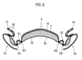
- Fig. 2 is a sectional view taken along the line F1-F1' of the absorbent article 1 shown in Fig. 1 .
- Fig.2 is also a sectional view when the absorbent article 1 is used.
- the wing portions 61 and 62 of the absorbent article 1 are folded to the side of the backsheet 20.
- the rubber 80 is arranged at the gathers 51 and 52.
- a basis weight of the absorber 30 that corresponds to the contact region S in which the wearer's excretion part and the topsheet 10 come into contact with each other is greater than that of an absorber that exists in a region S1 shown in Fig. 2 (between the first curved portion 101 and the second curved portion 201).
- the basis weight of the absorber 30 is greater than that of an absorber that exists in a region S2 (between the first curved portion 102 and the second curved portion 202).
- the basis weight of the absorber 30 is 500 g/m 2
- the basis weight of an absorber that exists in the region S1 is the basis weight of the absorber that exists in the region S2
- rigidity of a portion that corresponds to the contact region S of the absorbent article 1 is increased more than that in each of the regions S1 and S2.
- the first curved portions 101 and 102 and the second curved portions 201 and 202 are formed by means of compression processing.
- Fig. 3 is an enlarged view of the first curved portion 101.
- the first curved portion 101 is formed to be thinner than a thickness of the absorbent article 1 in the contact region S in which the wearer's excretion part and the topsheet 10 come into contact with each other.
- the first curved portion 101 is a groove that is formed in the topsheet 10.
- a bottom part of the groove has: a high compression region WH in which density of the absorber 30 is increased by means of compression processing; and a low compression region WL in which the density is lower than that in the high compression region WH.
- the low compression region WL is formed in a lattice shape.
- the absorbers opposed to each other via the first curved portion 101 are coupled with each other by means of the low compression region WL. It is preferable that a width W of the bottom part of the first curved portion 101 be within the range of 0.5 mm to 5 mm. If the width is 0.5 mm, rigidity of the bottom part cannot be ensured, and the bottom part may be severed. If 5 mm is exceeded, rigidity in a widthwise direction becomes too high, imparting a sense of discomfort to a wearer at the time of wearing.
- the first curved portion 102 and the second curved portions 201 and 202 also have a similar structure.
- the middle wide portions 101a and 102a of the first curved portion 101 and the first curved portion 102 are formed in a shape which convexes outwardly in the widthwise direction W of the absorbent article 1 in planar view. Therefore, a femoral part H of a wearer easily comes into contact with the middle wide portions 101a and 102a of the absorbent article 1.
- first curved portions 101 and 102 and the second curved portions 201 and 202 are formed to be thinner than a thickness of the absorbent article 1 in the contact region S in which the wearer's excretion part and the topsheet 10 come into contact with each other; and therefore, the absorbent article 1 is easily bendable at the first curved portions 101 and 102 and the second curved portions 201 and 202.
- a basis weight of the absorber 30 at a portion that forms the first curved portions 101 and 102 and the second curved portions 201 and 202 be within the range of 100 g/m 2 to 450 g/m 2 in a state before compression processing.
- a rigidity value of the absorber 30 that includes the first curved portions 101 and 102 and the second curved portions 201 and 202 be within the range of 500 mg to 2,500 mg (Galle rigidity value).
- the rigidity value is 500 mg or less, in a case where the absorbent article 1 is subjected to a force exerted from both sides in the widthwise direction to the inside in the widthwise direction, it is impossible to ensure the rigidity of the bottom part of the first curved portions 101 and 102 and the second curved portions 201 and 202, and the bottom part may be bent or folded; and therefore, the absorbent article 1 may not be able to transmit the force exerted from both sides in the widthwise direction to the inside in the widthwise direction into an extending direction of the first curved portions 101 and 102 and the second curved portions 201 and 202. In this case, an "action of deforming an absorbent article" to be described later hardly works.
- the rigidity value exceeds 2,500 mg, when the following characteristic arises relative to a wearer's lower body it readily imparts a sense of discomfort to a wearer.
- the absorbent article 1 When the absorbent article 1 is subjected to a force F exerted towards the inside in the widthwise direction, the absorbent article 1 bends to the side of the backsheet 20 while a portion (a groove bottom part) that is formed to be thin at the first curved portions 101 and 102 and the second curved portions 201 and 202 serves as a hinge.
- the region S1 between the first curved portion 101 and the second curved portion 201 and the region S2 between the first curved portion 101 and the second curved portion 202 moves to the side of the backsheet 30 of the absorbent article 1, and supports the middle region M in a direction approaching a wearer's skin. Therefore, an intimate contact property between the absorbent article 1 and the wearer can be increased.
- an absorption surface for body fluid in the topsheet 10 of the absorbent article 1 has the first curved portions 101 and 102 and the second curved portions 201 and 202 that are formed in a shape which convexes outwardly in the widthwise direction W; and therefore, even if a force is applied to the inside in the widthwise direction of the absorbent article 1 when in use, both side parts 31 and 32 of the absorber 30 are not narrowed. Therefore, this absorbent article 1 has an advantage that a sufficient absorption area is ensured in the middle region M of the absorbent article as well.
- the bottom part of the first curved portions 101 and 102 are compressed to thereby increase rigidity; and therefore, a force that is applied to the middle wide portions 101a and 102a to be exerted towards the inside in the widthwise direction lifts the absorber 30 in a direction approaching skin, and is transmitted along the first curved portions 101 and 102. As a result, this force acts in a direction which reduces an interval W1 between the forward narrow portions 101b and 102b and an interval W2 between the rearward narrow portions 101c and 102c.
- the force that is applied to the inside in the widthwise direction concentrates on the interval W1 between the forward narrow portions 101b and 102b and the interval W2 between the rearward narrow portions 101c and 102c. At this time, the force applied to the inside in the widthwise direction lifts the contact region S to the wearer's skin side. Further, the force F that is applied to the middle wide portions 101a and 102a to be exerted towards the inside in the widthwise direction extends the forward region F and the rearward region R outwardly in the widthwise direction of the absorbent article 1. The forward region F and the rearward region R are lifted in a direction approaching the skin side while being subjected to this force.
- the forward region F and the rearward region R are deformed in a cup shape while a space in the widthwise direction is ensured. Therefore, the contact region S comes into more intimate contact with the wearer's excretion part, making it possible to reliably receive body fluid which has flowed into the forward region F and the rearward region R.
- end parts of the first curved portions 101 and 102 are more inwardly positioned in the widthwise direction of the absorbent article more than the middle wide portions 101a and 102a. Therefore, when in use, even if body fluid gets into a space that is formed by the first curved portion 101, the second curved portion 202, and the region S1, shown in Fig. 2 , in excess of an absorption surface of the topsheet 10, the body fluid is guided to the first curved portions 101 and 102 and then flows to the side of the absorber 30. Therefore, leakage from the forward region F or the rearward region R of the absorbent article 1 can be prevented.
- the high compression region WH and the low compression region WL are formed by means of compression processing, and the low compression region WL is adapted to couple the absorbers 30 which are opposed to each other while the first curved portions are sandwiched therebetween.
- the low compression region WL is formed at the bottom part of a groove, whereby the absorbers 30 are not divided to be separated from each other; and therefore, the absorption capacity is not lost. Accordingly the absorbent article 1 is capable of increasing an intimate contact property between the absorbent article 1 and a wearer, and is also capable of reliably absorbing body fluid.
- a absorbent article 2 according to a second embodiment will be described with reference to Fig. 4 .
- Like constituent elements in the absorbent article 1 shown in Fig. 1 are designated by like reference numerals, and a detailed description is omitted.
- the first curved portions 101 and 102 shown in Fig. 1 are extended in a longitudinal direction of the absorbent article.
- main transversely crossing curved portions 111f and 111r are formed in a forward region F and a rearward region R.
- the main transversely crossing curved portions 111f and 111r are formed to be thinner than a thickness of the absorbent article 1 in a contact region S in which a wearer's excretion part and a topsheet 10 come into contact with each other.
- the main transversely crossing curved portions 111f and 111r are grooves that are formed in the topsheet 10.
- a high compression region WH and a low compression region WL are formed by means of compression processing, and the low compression region WL is formed in a lattice shape.
- the first curved portions 101 and 102 extend in a forward/backward direction more than end parts of the second curved portions 201 and 202 in a longitudinal direction of the absorbent article 2.
- the first curved portions 101 and 102 have middle wide portions 101a and 102a. At the middle wide portions 101a and 102a, an interval W0 between the first curved portions 101 and 102 is the widest.
- the first curved portions 101 and 102 have forward narrow portions 101b and 102b more forward than the middle wide portions 101a and 102b.
- an interval W1 between the first curved portions 101 and 102 is narrower than that between the middle wide portions 101a and 102a. That is, an interrelationship of W0 > W1 is established.
- the first curved portions 101 and 102 have rearward narrow portions 101ac and 102c more rearward than the middle wide portions 101a and 102a.
- an interval W2 between the first curved portions 101 and 102 is narrower than that between the middle wide portions 101a and 102a. That is, an interrelationship of W0 > W2 is established.
- the first curved portions 101 and 102 have forward wide portions 101d and 102d which are further forward than the forward narrow portions 101b and 102b.
- an interval W3 between the first curved portions 101 and 102 is wider than that between the forward narrow portions 101b and 102b. That is, an interrelationship of W3 > W1 is established.
- the first curved portions 101 and 102 have rearward wide portions 101e and 102e more rearward than the rearward narrow portions 101c and 102c.
- an interval W4 between the first curved portions 101 and 102 is wider than that between the rearward narrow portions 101c and 102c. That is, an interrelationship of W4 > W2 is established.
- the interval W0 between the middle wide portions 101a and 102a be within the range of 20 mm to 60 mm. If the interval W0 is 20 mm or less, an absorption quantity in the middle region M cannot be ensured. If 60 mm is exceeded, an average crotch interval of a wearer is exceeded, thus imparting a sense of discomfort to the wearer.
- the absorbent article 2 has a main transversely crossing curved portion 111f that extends in a widthwise direction of the absorbent article 2 between the forward wide portions 101d and 102d.
- the main transversely crossing curved portion 111f is formed in a curved shape having a convex shape in a forward direction. Both end parts in a widthwise direction of the main transversely crossing curved portion 111f are coupled with forward end parts of the curved portions 101 and 102.
- the absorbent article 2 has a main transversely crossing curved portion 111r that extends in a widthwise direction of the absorbent article 2 between the rearward wide portions 101e and 102e.
- the main transversely crossing curved portion 111r is formed in a curved shape having a convex shape in a rearward direction. Both end parts in a widthwise direction of the main transversely crossing curved portion 111r are coupled with rearward end parts of the first curved portions 101 and 102.
- a virtual line FL which is adapted to connect an end part 51ff of a free portion of a gather 51 and an end part 52ff of a free portion of a gather 52 to each other, and adapted to cross the pair of first curved portions 101 and 102.
- a virtual line RL which is adapted to connect an end part 51rf of a free portion of the gather 51 and an end part 52rf of a free portion of the gather 52 to each other, and adapted to cross the pair of first curved portions 101 and 102,.
- Fig. 5 is a schematic view illustrating a shape at the time of wearing the absorbent article 2 according to the embodiment.
- the middle wide portions 101a and 102a of the first curved portion 101 and the first curved portion 102 are formed in a shape which convexes outwardly in the widthwise direction W of the absorbent article 2 in planar view.
- a femoral part H of a wearer easily comes into contact with the middle wide portions 101a and 102a of the absorbent article 2.
- first curved portions 101 and 102 and the second curved portions 201 and 202 are formed to be thinner than a thickness of the absorbent article 1 in the contact region S in which the wearer's excretion part and the topsheet 10 come into contact with each other; and therefore, the absorbent article 1 is easily bendable at the first curved portions 101 and 102 and the second curved portions 201 and 202.
- the absorbent article 1 When the absorbent article 1 is subjected to a force F exerted towards the inside in the widthwise direction, the absorbent article 1 bends to the side of the backsheet 20 while a portion (a bottom part of a groove) formed to be thin at the first curved portions 101 and 102 and the second curved portions 201 and 202 serves as a hinge.
- a region S1 between the first curved portion 101 and the second curved portion 201 and a region S2 between the first curved portion 101 and the second curved portion 202 moves to the side of the backsheet 30 of the absorbent article 1, and supports a middle region M in a direction approaching a wearer's skin. Therefore, an intimate contact property between the absorbent article 1 and the wearer can be increased.
- a bottom part of the first curved portions 101 and 102 is compressed to thereby increase rigidity; and therefore, a force F that is applied to the middle wide portions 101a and 102a to be exerted towards the inside in the widthwise direction lifts the absorber 30 in a direction approaching skin, and is transmitted along the first curved portions 101 and 102. As a result, this force acts in a direction which reduces the interval W1 between the forward narrow portions 101b and 102b and the interval W2 between the rearward narrow portions 101c and 102c.
- the force F that is applied to the inside in the widthwise direction concentrates on the interval W1 between the forward narrow portions 101b and 102b and the interval W2 between the rearward narrow portions 101c and 102c. At this time, the force applied to the inside in the widthwise direction lifts the contact region S to the wearer's skin side. Further, the force F that is applied to the middle wide portions 101a and 102a to be exerted towards the inside in the widthwise direction is transmitted towards the forward wide portions 101d and 102d and the rearward wide portions 101e and 102e, and extends the forward region F and the rearward region R outwardly in the widthwise direction of the absorbent article 2.
- the forward region F and the rearward region R are pulled up in directions D1 and D2 approaching a skin side while being subjected to this force.
- the forward region F and the rearward region R are deformed in a cup shape while a space in the widthwise direction is ensured. Therefore, the contact region S comes into more intimate contact with the wearer's excretion part, making it possible to reliably receive body fluid flowing into the forward region F and the rearward region R.
- the absorbent article 2 has main transversely crossing curved portions 111f and 111r, whereby rigidity in the longitudinal direction is weakened, and thus, the absorbent article is easily bendable in the longitudinal direction. Therefore, when the force F is applied so that the absorbent article 2 is compressed inwardly in the widthwise direction of the absorbent article 2, the forward wide portions 101d and 102d and the rearward wide portions 10le and 102e are easily pulled towards the skin side, and are easily deformable into a cup shape.
- an absorption surface for body fluid in the topsheet 10 of the absorbent article 2 has the first curved portions 101 and 102 and the second curved portions 201 and 202 that are formed in a shape which convexes outwardly in the widthwise direction W
- the absorbent article 2 curves along the first curved portions 101 and 102 and the second curved portions 201 an 202, thereby preventing an occurrence of wrinkles extending in the longitudinal direction at a part of the absorber 30 that is positioned between the forward wide portions 101d and 102d and the rearward wide portions 101e and 102e or preventing an occurrence of folding in the longitudinal direction.
- the absorbent article 2 also has an advantage that a sufficient absorption area is ensured in the middle region M of the absorbent article 2.
- the forward narrow portions 101b and 102b and the rearward narrow portions 101c and 102c are positioned further inside in the widthwise direction of the absorbent article than the middle wide portions 101a and 102a.
- the high compression region WH and the low compression region WL are formed by means of compression processing, and the low compression region WL is adapted to couple the absorbers 30 that are opposed to each other while the absorbers and the first curved portions are sandwiched therebetween.
- the absorbers 30 are not divided to be separated from each other by means of the low compression region WL that is formed at the bottom part of a groove, and thus, an absorption capacity is not lost. Therefore, the absorbent article 2 is capable of increasing an intimate contact property between the absorbent article 2 and a wearer and is capable of reliably absorbing body fluid.
- FIG. 6 An absorbent article 3 according to a third embodiment will be described with reference to Fig. 6 .
- Like constituent elements in the absorbent articles 1 and 2 described above are designated by same reference numerals, and a detailed description is omitted.
- the first curved portions 101 and 102 shown in Fig. 1 are extended in a longitudinal direction of the absorbent article.
- main transversely crossing curved portions 111f and 111r are formed in a forward region F and a rearward region R. Further, subsidiary transversely crossing curved portions 112f and 112r are formed.
- the subsidiary transversely crossing curved portions 112f and 112r are formed to be thinner than a thickness of the absorbent article 1 in a contact region S in which a wearer's excretion part and a surface sheet 10 come into contact with each other.
- the subsidiary transversely crossing curved portions 112f and 112r are grooves that are formed in the surface sheet 10.
- a high compression region WH and a low compression region WL are formed by means of compression processing, and the low compression region WL is formed in a lattice shape.
- the first curved portions 101 and 102 and the second curved portions 201 and 202 are formed along a longitudinal direction of the absorbent article 3 on the surface of the surface sheet 10. Intervals between the first curved portions 101 and 102 in middle wide portions 101a and 102a, forward narrow portions 101b and 102b, rearward narrow portions 101c and 102c, and rearward wide portions 101e and 102e are identical to those in the second embodiment.
- the absorbent article 3 has the subsidiary transversely crossing curved portions 112f and 112r.
- the subsidiary transversely crossing curved portion 112f is formed more towards the side of a middle region M than the main transversely crossing curved portion 111f.
- the subsidiary transversely crossing curved portion 112f is formed in a curved shape having a convex shape in a forward direction.
- the subsidiary transversely crossing curved portion 112r is formed more towards the side of the middle region M than the main transversely crossing curved portion 111r.
- the subsidiary transversely crossing curved portion 112r is formed in a curved shape having a convex shape in a rearward direction.
- a virtual line FL which is adapted to connected an end part 51ff of a free portion of a gather 51 and an end part 52ff of a free portion of a gather 52 to each other, and adapted to cross the pair of first curved portions 101 and 102.
- the virtual line FL is adapted to cross the subsidiary transversely crossing curved portion 112f.
- a virtual line RL which is adapted to connected an end part 5lrf of a free portion of a gather 51 and an end part 52rf of a free portion of a gather 52 to each other, and adapted to cross the pair of first curved portions 101 and 102.
- the virtual line RL is adapted to cross the subsidiary transversely crossing curved portion 112r.
- the absorbent article 3 has the main transversely crossing curved portions 111f and 111r and the subsidiary transversely crossing curved portions 112f and 112r, whereby a portion at which rigidity in a longitudinal direction is weakened increases, and thus, the absorbent article is bendable more easily in the longitudinal direction. Therefore, the forward wide portions 101d and 102d and the rearward wide portions 101e and 102e are pulled towards a skin side more easily by means of a force F that is applied so that the absorbent article 3 is compressed inwardly in the widthwise direction of the absorbent article 3, and then, deformation into a cup shape is accelerated.
- an absorption surface for body fluid in the topsheet 10 of the absorbent article 3 has the first curved portions 101 and 102 and the second curved portions 201 and 202 that are formed in a shape which convexes outwardly in a widthwise direction W, even if the force F is applied inwardly in the widthwise direction of the absorbent article 3 when in use, both side parts 31 and 32 of an absorber 30 are not narrowed. Therefore, the absorbent article 3 also has an advantage that a sufficient absorption area is ensured in the middle region M of the absorbent article 3.
- the forward narrow portions 101b and 102b and the rearward narrow portions 101c and 102c are positioned further inside in the widthwise direction of the absorbent article than the middle wide portions 101a and 102a. Therefore, when in use, even in a case where body fluid gets into a space that is formed by the first curved portion 101, the second curved portion 202, and the region S1, shown in Fig. 2 , in excess of the absorption surface of the topsheet 10, the body fluid is guided to the first curved portions 101 and 102 and then flows to the side of the absorber 30. Therefore, leakage from the forward region F or the rearward region R of the absorbent article 3 can be prevented.
- the high compression region WH and the low compression region WL are formed by means of compression processing, and the low compression region WL is adapted to couple the absorbers 30 that are opposed to each other while the absorbers and the first curved portions are sandwiched therebetween.
- the low compression region WL is formed at the bottom part of a groove, whereby the absorbers 30 are not divided to be separated from each other; and therefore, the absorption capacity is not lost. Therefore, the absorbent article 3 is capable of increasing an intimate contact property between the absorbent article 3 and a wearer, and is also capable of reliably absorbing body fluid.
- the embodiments can be modified as follows. While the foregoing embodiments described that the absorbent article is a sanitary napkin, the embodiments can be applied to a so called liner or an incontinence article (referred to as an incontinence pad) or the like.
- the absorbent article is not limited to the planar shape disclosed in Fig. 1 described above.
- the absorbent article may be formed in a shape conforming to a shape of a wearer's crotch and a shape of shorts.
- a planar shape of the absorbent article can be formed in a variety of shapes such as a rectangular shape, an elliptical shape, or a gourd shape.
- the embodiments describe that, at the first curved portions 101 and 102, the second curved portions 201 and 202, the main transversely crossing curved portions 111f and 111r, and the subsidiary transversely crossing curved portions 112f and 112r, the high compression region WH in which density of the absorber 30 is increased and the low compression region WL in which the density is lower than that in the high compression region WH are formed in a lattice shape.
- a pattern which is formed by compression at the first curved portions 101 and 102, the second curved portions 201 and 202, the main transversely crossing curved portions 111f and 111r, and the subsidiary transversely crossing curved portions 112f and 112r, is not limited to the lattice shape.
- a dot shape, a wavy shape, a shaded shape or the like is employed.
- the rigidity in the longitudinal direction or widthwise direction of the absorbent article can be varied by varying the shape in the low compression region and the high compression shape.
- an absorbent article having a basis weight of the absorber 30, which is greater than that of each of the absorbent articles that are illustrated in the embodiments, is of such a type that a low compression region is formed in a ladder shape (a shaded shape), (that is, a continuous low compression region is not formed in a longitudinal direction), whereby rigidity of the absorbent article in which the rigidity in the longitudinal direction is likely to be high can be lowered.
- an intimate contact property with a wearer's excretion part can be increased, and a body fluid can be reliably absorbed.
Landscapes
- Health & Medical Sciences (AREA)
- Epidemiology (AREA)
- Engineering & Computer Science (AREA)
- Biomedical Technology (AREA)
- Heart & Thoracic Surgery (AREA)
- Vascular Medicine (AREA)
- Life Sciences & Earth Sciences (AREA)
- Animal Behavior & Ethology (AREA)
- General Health & Medical Sciences (AREA)
- Public Health (AREA)
- Veterinary Medicine (AREA)
- Dermatology (AREA)
- Physics & Mathematics (AREA)
- Fluid Mechanics (AREA)
- Absorbent Articles And Supports Therefor (AREA)
Abstract
Description
- The present invention relates to an absorbent article having a topsheet, a backsheet, and an absorber.
- Conventionally in an absorbent article such as a sanitary napkin, there is proposed that a groove is provided on a surface of a topsheet in order to improve fitting property between a wearer's skin and the absorbent article (refer to Patent Document 1). In
Patent Document 1, the shape of a groove is formed in a concave shape outward in a widthwise direction of the absorbent article. In the conventional absorbent article, a concave portion of the groove becomes fitted with the shape of a femoral part of a wearer, and a middle part of an absorber is intended to be lifted in a direction in which the middle part approaches a excretion part of the wearer by means of a compression force acting in a widthwise direction of the absorbent article from the femoral part of the wearer. - However, the conventional absorbent article mentioned above has entailed the following problem. That is, the shape of the groove is formed in a shape which concaves outwardly in the widthwise direction of the absorbent article. Therefore, in order to deform the shape of the absorbent article in the widthwise direction so that the middle part of the absorber is lifted in the direction in which the middle part approaches the excretion part of the wearer, a displacement is needed to such an extent that the middle part is pushed inward in the widthwise direction up to the vicinity of a top that is present innermost in the widthwise direction of the concave portion of the groove.
- Therefore, there has been a problem that a lifting effect of lifting the middle part of the absorber in a direction in which the middle part approaches the excretion part is not sufficiently achieved depending on the bodyline of a wearer or the shape or the like of underwear on which the absorbent article is to be worn. In addition, in a use state, that is, in a state in which the absorbent article is compressed in a widthwise direction of the absorbent article by the femoral part, an absorption surface middle part of the absorber is displaced, and thus, an absorption area has been sometimes decreased.
-
- Patent Document 1:
JP-A-2002-238948 Page 3,Fig. 1 , andFig. 3 ) - An absorbent article includes a topsheet having a contact surface which comes into contact with a skin of a wearer; a liquid-impermeable backsheet which does not permeate a liquid; and an absorber which is arranged between the topsheet and the backsheet, the absorbent article including a first curved portion and a second curved portion that are formed to be thinner than a thickness of the absorbent article in a contact region in which an excretion part of the wearer and the topsheet come into contact with each other. The first curved portion is arranged as a pair being symmetrical about a centerline of the absorbent article in a region in which the contact region is included, the region being an inside region which is more inward than each side part of the absorbent article in a widthwise direction, and is formed along a longitudinal direction of the absorbent article, the second curved portion is arranged as a pair in a region in which the contact region is included, the region being an inside region of the absorbent article in the widthwise direction that is more inward than the first curved portion, and is formed along the longitudinal direction of the absorbent article, and the first curved portion and the second curved portion have a shape which convexes outwardly in the widthwise direction of the absorbent article, in the region in which the contact region is included.
-
- [
Fig. 1] Fig. 1 is a plan view of an absorbent article according to a first embodiment. - [
Fig. 2] Fig. 2 is a sectional view taken along the line F1-F1' of the absorbent article of the first embodiment. - [
Fig. 3] Fig. 3 is an enlarged view illustrating a first bending unit according to the first embodiment. - [
Fig. 4] Fig. 4 is a plan view of an absorbent article according to a second embodiment. - [
Fig. 5] Fig. 5 is a schematic view illustrating a shape at the time of wearing the absorbent article according to the second embodiment. - [
Fig. 6] Fig. 6 is a plan view of an absorbent article according to a third embodiment. - An absorbent article according to each of the embodiments will be described with reference to the drawings. In the following description of the drawings, same or similar constituent elements are designated by same or similar reference numerals. However, it should be kept in mind that the drawings are merely schematic, and rates or the like of each dimension are different from actual ones. Therefore, specific dimensions or the like should be determined in consideration of the following description. In addition, of course, constituent elements with their different dimensional interrelationships or ratios are included in the respective drawings.
- An absorbent article according to a first embodiment will be described with reference to
Fig. 1. Fig. 1 is a plan view of anabsorbent article 1 according to the embodiment. - The
absorbent article 1 inFig. 1 is a sanitary napkin, for example. As shown inFig. 1 , theabsorbent article 1 has a forward region F, a middle region M, and a rearward region R. The forward region F comes into contact with a skin surface at a belly side of a wearer. The middle region M comes into contact with a skin surface in the vicinity of a vaginal opening of the wearer. The rearward region R comes into contact with a skin surface at a rear side of the wearer. - The
absorbent article 1 has: atopsheet 10 which comes into contact with a wearer's skin; a liquid-impermeable backsheet 20 which does not permeate a liquid; and an absorber 30. Theabsorber 30 is arranged between thetopsheet 10 and thebacksheet 20. Therefore, theabsorber 30 is indicated by the dotted line inFig. 1 . Theabsorber 30 is arranged at a middle portion in a longitudinal direction of theabsorbent article 1. In addition, theabsorbent article 1 hasside sheets absorber 30, which is orthogonal to a longitudinal direction L of theabsorbent article 1. Theabsorbent article 1 has: leakage prevention units (hereinafter, referred to as a "gathers") 51 and 52; andwing portions - Although not shown in
Fig. 1 , asecond sheet 11 may be provided between thetopsheet 10 and the absorber 30. - It is preferable that dimensions in a longitudinal direction of the
absorbent article 1 be within the range of 100 mm to 500 mm, and specifically it is further preferable that the dimensions be within the range of 150 mm to 420 mm. In addition, it is preferable that dimensions in a widthwise direction be within the range of 30 mm to 200 mm, and specifically it is preferable that the dimensions be within the range of 40 mm to 180 mm. - The
topsheet 10 has a length which is substantially equal to that of thebacksheet 20. The shape of an end part in a longitudinal direction of thetopsheet 10 is substantially identical to that of an end part in a longitudinal direction of thebacksheet 20. Thetopsheet 10 covers at least a surface of theabsorber 30. - The
topsheet 10 will be specifically described. - In the embodiment, the
topsheet 10 is a nonwoven cloth. A material for thetopsheet 10 is not limited in particular, as long as it is a sheet-like material with a structure for permeating a liquid, such as a woven cloth or a pored plastic sheet. As a material for a woven cloth or a nonwoven cloth, either of a natural fiber and a chemical fiber can be used. - As examples of natural fibers, there are exemplified celluloses such as ground pulp or cotton. As examples of chemical fibers, there are exemplified: reproducible celluloses such as rayon or fibril rayon; semisynthetic celluloses such as acetate or triacetate; thermoplastic hydrophobic chemical fibers; or thermoplastic hydrophobic chemical fibers or the like to which hydrophilic treatment is applied.
- As examples of thermoplastic hydrophobic chemical fibers, there are exemplified: single fibers such as polyethylene (PE), polypropylene (PP), or polyethylene terephthalate (PET); fibers made of graft polymerization of polyethylene and polypropylene; and composite fibers of core-clad structures or the like.
- As a web forming method of a nonwoven cloth, there can be employed any one of a dry type (such as a card technique, a spun bond technique, a melt blown technique, or an air-laid technique) and a wet type. Among the dry type technique and the wet type technique, a plurality of methods may be combined. In addition, a method such as thermal bonding, needle punching, or chemical bonding is exemplified. A method of producing nonwoven cloth is not limited to the abovementioned methods.
- Further, a spun lace that is formed in a sheet shape by means of a water tangling technique can also be employed for the
topsheet 10. Furthermore, nonwoven cloth having irregularities on a top layer side of the nonwoven cloth or an irregular nonwoven cloth obtained by providing total weight non-uniformity on the nonwoven cloth by applying air at the time of forming webs can also be employed for thetopsheet 10. By forming irregularities on a surface, it is possible to alleviate a body fluid from dispersing along a surface of thetopsheet 10 before penetrating thetopsheet 10. - Next, the
backsheet 20 will be specifically described. - In the embodiment, as the
backsheet 20, there can be employed a film which consists essentially of polyethylene, polypropylene or the like; an air ventilation resin film; or a sheet or the like obtained by bonding a ventilation resin film with a nonwoven cloth such as a spun bond or a spun lace. It is preferable that thebacksheet 20 be made of a material having flexibility to such an extent that a sense of discomfort at the time of wearing does not occur. For example, it is preferable to use a film which consists essentially of a low density polyethylene (LDPE) resin, a total weight (weight per unit area: also referred to as a basis weight) of which is within the range of 15 g/m2 to 30 g/m2. - Next, the
absorber 30 will be specifically described. - The
absorber 30 includes a hydrophilic fiber or pulp. As examples of hydrophilic fibers, there can be employed solely or in combination: celluloses such as ground pulp or cotton; reproducible celluloses such as rayon or fibril rayon; semisynthetic celluloses such as acetate or triacetate; particle-like polymers, fiber-like polymers, thermoplastic hydrophobic chemical fibers, or thermoplastic hydrophobic chemical fibers to which hydrophilic treatment is applied. Among them, it is preferable to use ground pulp in consideration of low cost and easiness of molding an absorber. - As the
absorber 30, a mixture of a polymeric absorber with a hydrophilic film may be used. In the embodiment, the polymeric absorber is a grain-like polymer such as a sodium acrylate copolymer having absorptivity and hygroscopic property. Theabsorber 30 may be an air-laid sheet obtained by molding a hydrophilic fiber or powder in a sheet shape by means of an air-laid technique. In a case where the air-laid sheet is used as theabsorber 30, it is preferable that a thickness of the air-laid sheet be 0.3 mm to 5.0 mm. As an example of air-laid sheet, there is employed the one obtained by molding a fiber and a grain-like polymer to be a sheet material by means of a binder or the like. The grain-like polymer may be dispersed in a layered shape or may be biased in a thickness direction in the air-laid sheet. - On the
absorber 30, embosses may be appropriately formed in order to prevent deformation or folding while in wearing or to adjust a thickness. These embosses for theabsorber 30 can be formed by passing the absorber between a patterned emboss roll and a flat roll. While the pattern for the emboss roll is formed in a lattice shape, in a dotted shape, or in a wavy shape, it is preferable to employ a lattice-shaped pattern which is easily adjusted in thickness. - The
side sheets - A material for the
side sheets topsheet 10. It is preferable to have hydrophobic property or water repellent property in order to prevent menstrual blood from flowing over theside sheets absorbent article 1 over theside sheets - The
side sheets topsheet 10. Theside sheet 41 covers a part of a side edge of theabsorber 30 and thewing 61. One end part of theside sheet 41 extending in a longitudinal direction is a substantially straight line, and superimposes on one end part of thetopsheet 10 extending in a longitudinal direction. The other end part of theside sheet 41 extending in the longitudinal direction is coincident with a part of an outer circumference of thebacksheet 20 and a shape of thewing portion 61. Theside sheet 42 covers a part of a side edge of theabsorber 30 and thewing portion 62. One end part of the side sheet 42extending in a longitudinal direction is a substantially straight line, and superimposes on the other end part of thetopsheet 10 extending in the longitudinal direction. The other end part of theside sheet 42 extending in the longitudinal direction is coincident with a part of an outer circumference of thebacksheet 20 and a shape of thewing portion 62. - The gathers 51 and 52 have a rubber 80 (not shown in
Fig. 1 , and refer toFig. 2 ) as a member having elasticity. The gathers 51 and 52 are provided at both side edges of theabsorber 30. The gathers 51 and 52 are arranged along the longitudinal direction L of theabsorbent article 1 in a state in which therubber 80 is expanded. The gather 51 is bonded with thetopsheet 10 atjoint units topsheet 10 atjoint units - Inwardly in the longitudinal direction L of the
absorbent article 1, beyond thejoint units topsheet 10. The gather 51 has end parts 51ff and 51rf of a free portion which is not bonded with thetopsheet 10. Inwardly in the longitudinal direction of theabsorbent article 1, beyond thejoint units topsheet 10. The gather 52 has end parts 52ff and 52rf of a free portion which is not bonded with thetopsheet 10. - In the
absorbent article 1, thetopsheet 10, theside sheets backsheet 20, and theabsorber 30 are bonded with each other. Circumferential edges of thetopsheet 10, theside sheets backsheet 20 are bonded with each other, and theabsorber 30 is internally sealed. As a method of bonding thetopsheet 10 and thebacksheet 20 with each other, it is possible to employ any one of heat emboss processing and ultrasonic or hot melt type adhesive agent or a combination of a plurality thereof. - In the
backsheet 20, on a surface coming into contact with shorts, an adhesive agent 70 is applied in a linear shape along a longitudinal direction of the backsheet 20 (not shown inFig. 1 , and refer toFig. 2 ). The adhesive agent 70 is applied in a plurality of lines along the longitudinal direction of thebacksheet 20. In each of thewing portion 61 and thewing portion 62, an adhesive agent is applied to a surface coming into contact with shorts as well. In a state before use, a protective sheet (not shown) for retaining stickiness is adhered as the adhesive agent 70. The protective sheet is released by a wearer when in use. - In the
absorbent article 1 according to the embodiment, on a surface of thebacksheet 10, firstcurved portions curved portions absorbent article 1. - The first
curved portion 101 is in an inside region which is more inward in planar view of theabsorbent article 1 than bothside parts absorber 30 in a widthwise direction, and is arranged as a pair symmetrical about a centerline CL of theabsorbent article 1. The firstcurved portions absorbent article 1 in the middle region M including a contact region S in which a wearer's excretion part and thetopsheet 10 come into contact with each other. The firstcurved portions absorbent article 1 in the contact region S in which the wearer's excretion part and thetopsheet 10 come into contact with each other. In the embodiment, the firstcurved portions topsheet 10. - The second
curved portions absorbent article 1. The secondcurved portions absorbent article 1 in the widthwise direction W and more inward than the firstcurved portions curved portions absorbent article 1 in the middle region M including the contact region S in which the wearer's excretion part and thetopsheet 10 come into contact with each other. The secondcurved portions absorbent article 1 in the contact region S in which the wearer's excretion part and thetopsheet 10 come into contact with each other. In the embodiment, the secondcurved portions topsheet 10. - The first
curved portions wide portions wide portions curved portions - The first
curved portions narrow portions wide portions narrow portions absorbent article 1, an interval W1 between the firstcurved portions wide portions - The first
curved portions narrow portions wide portions narrow portions absorbent article 1, an interval W2 between the firstcurved portions wide portions - Here, it is preferable that the interval W0 between the middle
wide portions -
Fig. 2 is a sectional view taken along the line F1-F1' of theabsorbent article 1 shown inFig. 1 .Fig.2 is also a sectional view when theabsorbent article 1 is used. InFig. 2 , thewing portions absorbent article 1 are folded to the side of thebacksheet 20. As shown inFig. 2 , therubber 80 is arranged at the gathers 51 and 52. - A basis weight of the
absorber 30 that corresponds to the contact region S in which the wearer's excretion part and thetopsheet 10 come into contact with each other is greater than that of an absorber that exists in a region S1 shown inFig. 2 (between the firstcurved portion 101 and the second curved portion 201). Similarly, the basis weight of theabsorber 30 is greater than that of an absorber that exists in a region S2 (between the firstcurved portion 102 and the second curved portion 202). For example, the basis weight of theabsorber 30 is 500 g/m2, and the basis weight of an absorber that exists in the region S1 (the basis weight of the absorber that exists in the region S2) is 200 g/m2. In this manner, rigidity of a portion that corresponds to the contact region S of theabsorbent article 1 is increased more than that in each of the regions S1 and S2. - In the embodiment, the first
curved portions curved portions Fig. 3 is an enlarged view of the firstcurved portion 101. The firstcurved portion 101 is formed to be thinner than a thickness of theabsorbent article 1 in the contact region S in which the wearer's excretion part and thetopsheet 10 come into contact with each other. The firstcurved portion 101 is a groove that is formed in thetopsheet 10. A bottom part of the groove has: a high compression region WH in which density of theabsorber 30 is increased by means of compression processing; and a low compression region WL in which the density is lower than that in the high compression region WH. In the embodiment, the low compression region WL is formed in a lattice shape. The absorbers opposed to each other via the firstcurved portion 101 are coupled with each other by means of the low compression region WL. It is preferable that a width W of the bottom part of the firstcurved portion 101 be within the range of 0.5 mm to 5 mm. If the width is 0.5 mm, rigidity of the bottom part cannot be ensured, and the bottom part may be severed. If 5 mm is exceeded, rigidity in a widthwise direction becomes too high, imparting a sense of discomfort to a wearer at the time of wearing. The firstcurved portion 102 and the secondcurved portions - In the
absorbent article 1, the middlewide portions curved portion 101 and the firstcurved portion 102 are formed in a shape which convexes outwardly in the widthwise direction W of theabsorbent article 1 in planar view. Therefore, a femoral part H of a wearer easily comes into contact with the middlewide portions absorbent article 1. - In addition, the first
curved portions curved portions absorbent article 1 in the contact region S in which the wearer's excretion part and thetopsheet 10 come into contact with each other; and therefore, theabsorbent article 1 is easily bendable at the firstcurved portions curved portions - Here, it is preferable that a basis weight of the
absorber 30 at a portion that forms the firstcurved portions curved portions absorber 30 that includes the firstcurved portions curved portions - If the rigidity value is 500 mg or less, in a case where the
absorbent article 1 is subjected to a force exerted from both sides in the widthwise direction to the inside in the widthwise direction, it is impossible to ensure the rigidity of the bottom part of the firstcurved portions curved portions absorbent article 1 may not be able to transmit the force exerted from both sides in the widthwise direction to the inside in the widthwise direction into an extending direction of the firstcurved portions curved portions - Alternatively if the rigidity value exceeds 2,500 mg, when the following characteristic arises relative to a wearer's lower body it readily imparts a sense of discomfort to a wearer.
- When the
absorbent article 1 is subjected to a force F exerted towards the inside in the widthwise direction, theabsorbent article 1 bends to the side of thebacksheet 20 while a portion (a groove bottom part) that is formed to be thin at the firstcurved portions curved portions curved portion 101 and the secondcurved portion 201 and the region S2 between the firstcurved portion 101 and the secondcurved portion 202 moves to the side of thebacksheet 30 of theabsorbent article 1, and supports the middle region M in a direction approaching a wearer's skin. Therefore, an intimate contact property between theabsorbent article 1 and the wearer can be increased. - In addition, an absorption surface for body fluid in the
topsheet 10 of theabsorbent article 1 has the firstcurved portions curved portions absorbent article 1 when in use, bothside parts absorber 30 are not narrowed. Therefore, thisabsorbent article 1 has an advantage that a sufficient absorption area is ensured in the middle region M of the absorbent article as well. - Hereinafter, an action of deforming the absorbent article will be described. The bottom part of the first
curved portions wide portions absorber 30 in a direction approaching skin, and is transmitted along the firstcurved portions narrow portions narrow portions - The force that is applied to the inside in the widthwise direction concentrates on the interval W1 between the forward
narrow portions narrow portions wide portions absorbent article 1. The forward region F and the rearward region R are lifted in a direction approaching the skin side while being subjected to this force. Thus, the forward region F and the rearward region R, are deformed in a cup shape while a space in the widthwise direction is ensured. Therefore, the contact region S comes into more intimate contact with the wearer's excretion part, making it possible to reliably receive body fluid which has flowed into the forward region F and the rearward region R. - In addition, in the
absorbent article 1, end parts of the firstcurved portions 101 and 102 (the forwardnarrow portions narrow portions wide portions curved portion 101, the secondcurved portion 202, and the region S1, shown inFig. 2 , in excess of an absorption surface of thetopsheet 10, the body fluid is guided to the firstcurved portions absorber 30. Therefore, leakage from the forward region F or the rearward region R of theabsorbent article 1 can be prevented. - Further, at the first
curved portions curved portions absorbent article 1, the high compression region WH and the low compression region WL are formed by means of compression processing, and the low compression region WL is adapted to couple theabsorbers 30 which are opposed to each other while the first curved portions are sandwiched therebetween. In the embodiment, the low compression region WL is formed at the bottom part of a groove, whereby theabsorbers 30 are not divided to be separated from each other; and therefore, the absorption capacity is not lost. Accordingly theabsorbent article 1 is capable of increasing an intimate contact property between theabsorbent article 1 and a wearer, and is also capable of reliably absorbing body fluid. - A absorbent article 2 according to a second embodiment will be described with reference to
Fig. 4 . Like constituent elements in theabsorbent article 1 shown inFig. 1 are designated by like reference numerals, and a detailed description is omitted. In the absorbent article 2 shown inFig. 4 , the firstcurved portions Fig. 1 are extended in a longitudinal direction of the absorbent article. In addition, main transversely crossingcurved portions curved portions absorbent article 1 in a contact region S in which a wearer's excretion part and atopsheet 10 come into contact with each other. - In the embodiment, the main transversely crossing
curved portions topsheet 10. At the main transversely crossingcurved portion 111f and the main transversely crossingcurved portion 111r, like the firstcurved portions curved portions - In the absorbent article 2, the first
curved portions curved portions curved portions wide portions wide portions curved portions - The first
curved portions narrow portions wide portions narrow portions curved portions wide portions - The first
curved portions wide portions narrow portions curved portions wide portions - The first
curved portions wide portions narrow portions wide portions curved portions narrow portions - The first
curved portions wide portions narrow portions wide portions curved portions narrow portions - Here, it is preferable that the interval W0 between the middle
wide portions - The absorbent article 2 has a main transversely crossing
curved portion 111f that extends in a widthwise direction of the absorbent article 2 between the forwardwide portions curved portion 111f is formed in a curved shape having a convex shape in a forward direction. Both end parts in a widthwise direction of the main transversely crossingcurved portion 111f are coupled with forward end parts of thecurved portions - In addition, the absorbent article 2 has a main transversely crossing
curved portion 111r that extends in a widthwise direction of the absorbent article 2 between the rearwardwide portions curved portion 111r is formed in a curved shape having a convex shape in a rearward direction. Both end parts in a widthwise direction of the main transversely crossingcurved portion 111r are coupled with rearward end parts of the firstcurved portions - A virtual line FL, which is adapted to connect an end part 51ff of a free portion of a gather 51 and an end part 52ff of a free portion of a gather 52 to each other, and adapted to cross the pair of first
curved portions - A virtual line RL, which is adapted to connect an end part 51rf of a free portion of the gather 51 and an end part 52rf of a free portion of the gather 52 to each other, and adapted to cross the pair of first
curved portions -
Fig. 5 is a schematic view illustrating a shape at the time of wearing the absorbent article 2 according to the embodiment. In the absorbent article 2, the middlewide portions curved portion 101 and the firstcurved portion 102 are formed in a shape which convexes outwardly in the widthwise direction W of the absorbent article 2 in planar view. Thus, a femoral part H of a wearer easily comes into contact with the middlewide portions - In addition, the first
curved portions curved portions absorbent article 1 in the contact region S in which the wearer's excretion part and thetopsheet 10 come into contact with each other; and therefore, theabsorbent article 1 is easily bendable at the firstcurved portions curved portions - When the
absorbent article 1 is subjected to a force F exerted towards the inside in the widthwise direction, theabsorbent article 1 bends to the side of thebacksheet 20 while a portion (a bottom part of a groove) formed to be thin at the firstcurved portions curved portions curved portion 101 and the secondcurved portion 201 and a region S2 between the firstcurved portion 101 and the secondcurved portion 202 moves to the side of thebacksheet 30 of theabsorbent article 1, and supports a middle region M in a direction approaching a wearer's skin. Therefore, an intimate contact property between theabsorbent article 1 and the wearer can be increased. - In addition, a bottom part of the first
curved portions wide portions absorber 30 in a direction approaching skin, and is transmitted along the firstcurved portions narrow portions narrow portions - The force F that is applied to the inside in the widthwise direction concentrates on the interval W1 between the forward
narrow portions narrow portions wide portions wide portions wide portions - The absorbent article 2 has main transversely crossing
curved portions wide portions - In addition, an absorption surface for body fluid in the
topsheet 10 of the absorbent article 2 has the firstcurved portions curved portions curved portions curved portions 201 an 202, thereby preventing an occurrence of wrinkles extending in the longitudinal direction at a part of theabsorber 30 that is positioned between the forwardwide portions wide portions absorber 30. In this manner, bothside parts absorber 30 are never narrowed. Therefore, the absorbent article 2 also has an advantage that a sufficient absorption area is ensured in the middle region M of the absorbent article 2. - Further, in the absorbent article 2, the forward
narrow portions narrow portions wide portions curved portion 101, the secondcurved portion 202, and the region S1 shown inFig. 2 , in excess of the absorption surface of thetopsheet 10, the body fluid is guided to the firstcurved portions absorber 30. Therefore, leakage from the forward region F or the rearward region R of the absorbent article 2 can be prevented. - Furthermore, at the first
curved portions curved portions absorbers 30 that are opposed to each other while the absorbers and the first curved portions are sandwiched therebetween. In the embodiment, theabsorbers 30 are not divided to be separated from each other by means of the low compression region WL that is formed at the bottom part of a groove, and thus, an absorption capacity is not lost. Therefore, the absorbent article 2 is capable of increasing an intimate contact property between the absorbent article 2 and a wearer and is capable of reliably absorbing body fluid. - An
absorbent article 3 according to a third embodiment will be described with reference toFig. 6 . Like constituent elements in theabsorbent articles 1 and 2 described above are designated by same reference numerals, and a detailed description is omitted. In theabsorbent article 3 shown inFig. 6 , the firstcurved portions Fig. 1 are extended in a longitudinal direction of the absorbent article. In addition, main transversely crossingcurved portions curved portions curved portions absorbent article 1 in a contact region S in which a wearer's excretion part and asurface sheet 10 come into contact with each other. In the embodiment, the subsidiary transversely crossingcurved portions surface sheet 10. - In the embodiment, in the subsidiary transversely crossing
curved portions curved portions curved portions - In the
absorbent article 3 according to the embodiment, the firstcurved portions curved portions absorbent article 3 on the surface of thesurface sheet 10. Intervals between the firstcurved portions wide portions narrow portions narrow portions wide portions - The
absorbent article 3 has the subsidiary transversely crossingcurved portions curved portion 112f is formed more towards the side of a middle region M than the main transversely crossingcurved portion 111f. The subsidiary transversely crossingcurved portion 112f is formed in a curved shape having a convex shape in a forward direction. The subsidiary transversely crossingcurved portion 112r is formed more towards the side of the middle region M than the main transversely crossingcurved portion 111r. The subsidiary transversely crossingcurved portion 112r is formed in a curved shape having a convex shape in a rearward direction. - A virtual line FL, which is adapted to connected an end part 51ff of a free portion of a gather 51 and an end part 52ff of a free portion of a gather 52 to each other, and adapted to cross the pair of first
curved portions curved portion 112f. - A virtual line RL, which is adapted to connected an end part 5lrf of a free portion of a gather 51 and an end part 52rf of a free portion of a gather 52 to each other, and adapted to cross the pair of first
curved portions curved portion 112r. - As described above, the
absorbent article 3 has the main transversely crossingcurved portions curved portions wide portions wide portions absorbent article 3 is compressed inwardly in the widthwise direction of theabsorbent article 3, and then, deformation into a cup shape is accelerated. - In addition, since an absorption surface for body fluid in the
topsheet 10 of theabsorbent article 3 has the firstcurved portions curved portions absorbent article 3 when in use, bothside parts absorber 30 are not narrowed. Therefore, theabsorbent article 3 also has an advantage that a sufficient absorption area is ensured in the middle region M of theabsorbent article 3. - Further, in the
absorbent article 3, the forwardnarrow portions narrow portions wide portions curved portion 101, the secondcurved portion 202, and the region S1, shown inFig. 2 , in excess of the absorption surface of thetopsheet 10, the body fluid is guided to the firstcurved portions absorber 30. Therefore, leakage from the forward region F or the rearward region R of theabsorbent article 3 can be prevented. - Furthermore, at the first
curved portions curved portions absorbent article 3, the high compression region WH and the low compression region WL are formed by means of compression processing, and the low compression region WL is adapted to couple theabsorbers 30 that are opposed to each other while the absorbers and the first curved portions are sandwiched therebetween. In the embodiment, the low compression region WL is formed at the bottom part of a groove, whereby theabsorbers 30 are not divided to be separated from each other; and therefore, the absorption capacity is not lost. Therefore, theabsorbent article 3 is capable of increasing an intimate contact property between theabsorbent article 3 and a wearer, and is also capable of reliably absorbing body fluid. - As described above, while the contents of the present invention were disclosed through the first to fourth embodiments, it should not be understood that the discussion and drawings forming a part of this disclosure limit the present invention. From this disclosure, a variety of substitute embodiments, examples, and operational techniques would have been self-evident to one skilled in the art.
- The embodiments can be modified as follows. While the foregoing embodiments described that the absorbent article is a sanitary napkin, the embodiments can be applied to a so called liner or an incontinence article (referred to as an incontinence pad) or the like.
- The absorbent article is not limited to the planar shape disclosed in
Fig. 1 described above. The absorbent article may be formed in a shape conforming to a shape of a wearer's crotch and a shape of shorts. A planar shape of the absorbent article can be formed in a variety of shapes such as a rectangular shape, an elliptical shape, or a gourd shape. - The embodiments describe that, at the first
curved portions curved portions curved portions curved portions absorber 30 is increased and the low compression region WL in which the density is lower than that in the high compression region WH are formed in a lattice shape. - However, a pattern, which is formed by compression at the first
curved portions curved portions curved portions curved portions absorber 30, which is greater than that of each of the absorbent articles that are illustrated in the embodiments, is of such a type that a low compression region is formed in a ladder shape (a shaded shape), (that is, a continuous low compression region is not formed in a longitudinal direction), whereby rigidity of the absorbent article in which the rigidity in the longitudinal direction is likely to be high can be lowered. - As described above, of course, the present invention includes a variety of embodiments or the like, which are not described herein. Therefore, a technical scope of the present invention is defined by only the specific matters of the invention according to the claims that are reasonable from the foregoing description.
- The whole contents of JP-A-2009-096525 (filed in April 10, 2009) are incorporated in the present specification by reference.
- According to the present invention, an intimate contact property with a wearer's excretion part can be increased, and a body fluid can be reliably absorbed.
Claims (8)
- An absorbent article comprising: a topsheet having a contact surface which comes into contact with a skin of a wearer; a liquid-impermeable backsheet which does not permeate a liquid; and an absorber which is arranged between the topsheet and the backsheet, the absorbent article including a first curved portion and a second curved portion that are formed to be thinner than a thickness of the absorbent article in a contact region in which an excretion part of the wearer and the topsheet come into contact with each other, wherein:the first curved portion is arranged as a pair being symmetrical about a centerline of the absorbent article in a region in which the contact region is included, the region being an inside region being more inward than each side part of the absorbent article in a widthwise direction, and is formed along a longitudinal direction of the absorbent article;the second curved portion is arranged as a pair in a region in which the contact region is included, the region being an inside region of the absorbent article in the widthwise direction that is more inward than the first curved portion, and is formed along the longitudinal direction of the absorbent article; andthe first curved portion and the second curved portion have a shape which convexes outwardly in the widthwise direction of the absorbent article, in the region in which the contact region is included.
- The absorbent article according to claim 1, wherein at least the first curved portion has:
a middle wide portion in which an interval between the pair of first curved portions is the widest; a forward narrow portion in which the interval between the pair of first curved portions is narrower than an interval in the wide portion, at a site which is more forward than the wide portion in a use state of the absorbent article;
a rearward narrow portion in which the interval between the pair of first curved portions is narrower than the wide portion, at a site which is more rearward than an interval in the wide portion in the use state of the absorbent article;
a forward wide portion in which the interval between the pair of first curved portions is wider than the forward narrow portion, at a site that is more forward than an interval in the forward narrow portion; and
a rearward wide portion in which the interval between the pair of first curved portions is wider than an interval in the rearward narrow portion, at a site which is more rearward than the rearward narrow portion. - The absorbent article according to claim 2, wherein the absorbent article has a main transversely crossing curved portion which is arranged between one pair of forward wide portions including the forward wide portion or between one pair of rearward wide portions including the rearward wide portion, and which extends in a widthwise direction of the absorbent article.
- The absorbent article according to claim 2, wherein the absorbent article has at least one subsidiary transversely crossing curved portion which is arranged more towards a side of the middle region than the main transversely crossing curved portion, and which extends in the widthwise direction of the absorbent article.
- The absorbent article according to claim 4, having one pair of leakage prevention units which are arranged at positions that correspond to both side parts of the absorber, in a planar view of the absorbent article, wherein: a virtual line which is parallel to the widthwise direction of the absorbent article, and which is adapted to connect end parts of a free portion, excluding a joint unit with the topsheet, of one pair of the leakage prevention units, is adapted to cross the pair of first curved portions and the virtual line is adapted to cross the main transversely crossing curved portion or the subsidiary transversely crossing curved portion.
- The absorbent article according to claim 1, wherein a basis weight of an absorber that exists at a position corresponding to the contact region is greater than a basis weight of an absorber that exists between the first curved portion and the second curved portion.
- The absorbent article according to claim 1, wherein the first curved portion and the second curved portion are formed by means of compression processing.
- The absorbent article according to claim 7, wherein at least the first curved portion has: a high compression region in which density of an absorber is increased by means of the compression processing; and a low compression region which is lower in density than the high compression region, and wherein the absorbers opposed to each other via the first curved portion are coupled with each other by means of the low compression region.
Applications Claiming Priority (2)
| Application Number | Priority Date | Filing Date | Title |
|---|---|---|---|
| JP2009096525A JP5602382B2 (en) | 2009-04-10 | 2009-04-10 | Absorbent articles |
| PCT/JP2010/056311 WO2010117015A1 (en) | 2009-04-10 | 2010-04-07 | Absorptive article |
Publications (2)
| Publication Number | Publication Date |
|---|---|
| EP2417950A1 true EP2417950A1 (en) | 2012-02-15 |
| EP2417950A4 EP2417950A4 (en) | 2013-04-10 |
Family
ID=42936296
Family Applications (1)
| Application Number | Title | Priority Date | Filing Date |
|---|---|---|---|
| EP10761714.4A Withdrawn EP2417950A4 (en) | 2009-04-10 | 2010-04-07 | Absorptive article |
Country Status (7)
| Country | Link |
|---|---|
| US (1) | US9029626B2 (en) |
| EP (1) | EP2417950A4 (en) |
| JP (1) | JP5602382B2 (en) |
| KR (1) | KR20110139751A (en) |
| CN (1) | CN102387766A (en) |
| SG (1) | SG175101A1 (en) |
| WO (1) | WO2010117015A1 (en) |
Families Citing this family (49)
| Publication number | Priority date | Publication date | Assignee | Title |
|---|---|---|---|---|
| ES2314137T3 (en) | 2003-02-12 | 2009-03-16 | THE PROCTER & GAMBLE COMPANY | COMFORTABLE diaper. |
| EP1447067B1 (en) | 2003-02-12 | 2007-12-05 | The Procter & Gamble Company | Thin and dry diaper |
| DE112008000011B4 (en) | 2007-06-18 | 2013-11-28 | The Procter & Gamble Company | Disposable absorbent articles and their use |
| ES2443535T3 (en) | 2007-06-18 | 2014-02-19 | The Procter & Gamble Company | Disposable absorbent article with substantially continuous continuously distributed particle-shaped polymeric material and method |
| CN102014826A (en) | 2008-04-29 | 2011-04-13 | 宝洁公司 | Method of making absorbent core with strain resistant core cover |
| EP2329803B1 (en) | 2009-12-02 | 2019-06-19 | The Procter & Gamble Company | Apparatus and method for transferring particulate material |
| JP2012085800A (en) * | 2010-10-19 | 2012-05-10 | Kao Corp | Absorbent article |
| JP5684046B2 (en) * | 2011-05-20 | 2015-03-11 | ユニ・チャーム株式会社 | Absorbent articles |
| PL2532328T3 (en) | 2011-06-10 | 2014-07-31 | Procter & Gamble | Method and apparatus for making absorbent structures with absorbent material |
| PL3111903T5 (en) | 2011-06-10 | 2022-02-14 | The Procter And Gamble Company | Absorbent structure for absorbent articles |
| ES2484695T5 (en) | 2011-06-10 | 2018-02-13 | The Procter & Gamble Company | Disposable diaper that has a reduced joint between the absorbent core and the backing sheet |
| EP2532329B1 (en) | 2011-06-10 | 2018-09-19 | The Procter and Gamble Company | Method and apparatus for making absorbent structures with absorbent material |
| WO2012170781A1 (en) | 2011-06-10 | 2012-12-13 | The Procter & Gamble Company | Disposable diapers |
| EP2717822B1 (en) | 2011-06-10 | 2019-06-05 | The Procter and Gamble Company | Absorbent core for disposable absorbent articles |
| PH12013502575A1 (en) | 2011-06-10 | 2014-02-10 | Procter & Gamble | Absorbent structure for absorbent articles |
| KR101628044B1 (en) * | 2012-02-14 | 2016-06-08 | 다이오세이시가부시끼가이샤 | Absorbent article provided with novel leg gathers |
| JP2013215388A (en) * | 2012-04-09 | 2013-10-24 | Unicharm Corp | Absorbent article |
| JP5670960B2 (en) * | 2012-06-11 | 2015-02-18 | 花王株式会社 | Absorbent articles |
| JP6001984B2 (en) * | 2012-10-01 | 2016-10-05 | 花王株式会社 | Absorbent articles |
| MX348890B (en) | 2012-11-13 | 2017-07-03 | Procter & Gamble | Absorbent articles with channels and signals. |
| US8979815B2 (en) | 2012-12-10 | 2015-03-17 | The Procter & Gamble Company | Absorbent articles with channels |
| US9216116B2 (en) | 2012-12-10 | 2015-12-22 | The Procter & Gamble Company | Absorbent articles with channels |
| EP2740449B1 (en) | 2012-12-10 | 2019-01-23 | The Procter & Gamble Company | Absorbent article with high absorbent material content |
| US9216118B2 (en) | 2012-12-10 | 2015-12-22 | The Procter & Gamble Company | Absorbent articles with channels and/or pockets |
| EP2740452B1 (en) | 2012-12-10 | 2021-11-10 | The Procter & Gamble Company | Absorbent article with high absorbent material content |
| EP2740450B1 (en) | 2012-12-10 | 2025-12-31 | The Procter & Gamble Company | Absorbent item with a high proportion of superabsorbent material |
| US10639215B2 (en) | 2012-12-10 | 2020-05-05 | The Procter & Gamble Company | Absorbent articles with channels and/or pockets |
| EP3254656B1 (en) | 2013-06-14 | 2021-11-10 | The Procter & Gamble Company | Absorbent article and absorbent core forming channels when wet |
| US9987176B2 (en) | 2013-08-27 | 2018-06-05 | The Procter & Gamble Company | Absorbent articles with channels |
| CN110013386B (en) | 2013-08-27 | 2021-10-01 | 宝洁公司 | Absorbent article with channels |
| CA2924828C (en) | 2013-09-16 | 2017-07-18 | The Procter & Gamble Company | Absorbent articles with channels and signals |
| US11207220B2 (en) | 2013-09-16 | 2021-12-28 | The Procter & Gamble Company | Absorbent articles with channels and signals |
| EP3351225B1 (en) | 2013-09-19 | 2021-12-29 | The Procter & Gamble Company | Absorbent cores having material free areas |
| ES2606320T3 (en) | 2013-12-19 | 2017-03-23 | The Procter & Gamble Company | Absorbent cores that have channel-forming areas and wrapping joints in c |
| US9789009B2 (en) | 2013-12-19 | 2017-10-17 | The Procter & Gamble Company | Absorbent articles having channel-forming areas and wetness indicator |
| EP2905001B1 (en) | 2014-02-11 | 2017-01-04 | The Procter and Gamble Company | Method and apparatus for making an absorbent structure comprising channels |
| US10271997B2 (en) | 2014-04-08 | 2019-04-30 | The Procter & Gamble Company | Absorbent articles having substrates having zonal treatments |
| EP2949300B1 (en) | 2014-05-27 | 2017-08-02 | The Procter and Gamble Company | Absorbent core with absorbent material pattern |
| JP5972945B2 (en) * | 2014-09-30 | 2016-08-17 | 大王製紙株式会社 | Absorbent articles |
| WO2016103482A1 (en) * | 2014-12-26 | 2016-06-30 | ユニ・チャーム株式会社 | Disposable diaper |
| RU2017133027A (en) | 2015-03-16 | 2019-04-16 | Дзе Проктер Энд Гэмбл Компани | Rugged Absorbent Products |
| CN107405242A (en) | 2015-03-16 | 2017-11-28 | 宝洁公司 | Absorbent article with improved core |
| MX2017014428A (en) | 2015-05-12 | 2018-04-10 | Procter & Gamble | Absorbent article with improved core-to-backsheet adhesive. |
| US10543129B2 (en) | 2015-05-29 | 2020-01-28 | The Procter & Gamble Company | Absorbent articles having channels and wetness indicator |
| JP6333223B2 (en) * | 2015-09-07 | 2018-05-30 | ユニ・チャーム株式会社 | Absorbent articles |
| EP3167859B1 (en) | 2015-11-16 | 2020-05-06 | The Procter and Gamble Company | Absorbent cores having material free areas |
| EP3238676B1 (en) | 2016-04-29 | 2019-01-02 | The Procter and Gamble Company | Absorbent core with profiled distribution of absorbent material |
| EP3238678B1 (en) | 2016-04-29 | 2019-02-27 | The Procter and Gamble Company | Absorbent core with transversal folding lines |
| JP7263189B2 (en) * | 2019-09-19 | 2023-04-24 | 大王製紙株式会社 | absorbent article |
Family Cites Families (15)
| Publication number | Priority date | Publication date | Assignee | Title |
|---|---|---|---|---|
| TW545221U (en) | 1997-05-06 | 2003-08-01 | Kao Corp | Absorbent article |
| JP3801449B2 (en) | 2001-02-20 | 2006-07-26 | 花王株式会社 | Absorbent articles |
| JP4180865B2 (en) * | 2002-09-09 | 2008-11-12 | ユニ・チャーム株式会社 | Absorbent article with flexible shaft |
| US7686790B2 (en) * | 2003-03-04 | 2010-03-30 | Kimberly-Clark Worldwide, Inc. | Nonlinear, undulating perimeter embossing in an absorbent article |
| WO2006060526A1 (en) * | 2004-11-30 | 2006-06-08 | The Procter & Gamble Company | Absorbent article having outwardly convex longitudinal central channels for improved protection |
| KR101198546B1 (en) * | 2005-05-20 | 2012-11-06 | 유한킴벌리 주식회사 | Absorbent article including macro-embossings comprising a plurality of micro-embossings and having enhanced bunching and leaking preventing efficiency and aesthetic effect |
| EP1885315A1 (en) * | 2005-06-02 | 2008-02-13 | The Procter and Gamble Company | Absorbent article having traverse reinforcing element |
| JP4619253B2 (en) * | 2005-09-29 | 2011-01-26 | 花王株式会社 | Absorbent articles |
| JP4953618B2 (en) * | 2005-11-02 | 2012-06-13 | ユニ・チャーム株式会社 | Absorbent articles |
| JP5080189B2 (en) * | 2006-10-06 | 2012-11-21 | 花王株式会社 | Sanitary napkin |
| JP5123579B2 (en) * | 2007-06-22 | 2013-01-23 | ユニ・チャーム株式会社 | Absorbent articles |
| JP2009096525A (en) | 2007-10-18 | 2009-05-07 | Nissei Kagaku Kk | Food container |
| JP5258379B2 (en) * | 2008-05-15 | 2013-08-07 | ユニ・チャーム株式会社 | Absorbent articles |
| JP5503867B2 (en) | 2008-12-15 | 2014-05-28 | 花王株式会社 | Absorbent article and manufacturing method thereof |
| JP5292083B2 (en) * | 2008-12-15 | 2013-09-18 | 花王株式会社 | Absorbent articles |
-
2009
- 2009-04-10 JP JP2009096525A patent/JP5602382B2/en not_active Expired - Fee Related
-
2010
- 2010-04-07 US US13/263,737 patent/US9029626B2/en not_active Expired - Fee Related
- 2010-04-07 KR KR1020117024759A patent/KR20110139751A/en not_active Ceased
- 2010-04-07 CN CN2010800159677A patent/CN102387766A/en active Pending
- 2010-04-07 EP EP10761714.4A patent/EP2417950A4/en not_active Withdrawn
- 2010-04-07 SG SG2011072964A patent/SG175101A1/en unknown
- 2010-04-07 WO PCT/JP2010/056311 patent/WO2010117015A1/en not_active Ceased
Also Published As
| Publication number | Publication date |
|---|---|
| KR20110139751A (en) | 2011-12-29 |
| SG175101A1 (en) | 2011-11-28 |
| JP2010246614A (en) | 2010-11-04 |
| US9029626B2 (en) | 2015-05-12 |
| EP2417950A4 (en) | 2013-04-10 |
| CN102387766A (en) | 2012-03-21 |
| US20120095425A1 (en) | 2012-04-19 |
| JP5602382B2 (en) | 2014-10-08 |
| WO2010117015A1 (en) | 2010-10-14 |
Similar Documents
| Publication | Publication Date | Title |
|---|---|---|
| US9029626B2 (en) | Absorbent article | |
| US7335810B2 (en) | Absorbent article having extended cushion layer with corrugated topsheet | |
| JP3850102B2 (en) | Absorbent articles | |
| JP4352027B2 (en) | Absorbent articles | |
| JP4180865B2 (en) | Absorbent article with flexible shaft | |
| JP4540104B2 (en) | Absorbent articles | |
| JP4492957B2 (en) | Absorbent articles | |
| JP5305812B2 (en) | Absorbent articles | |
| JP4390445B2 (en) | Long absorbent article | |
| EP2851045B1 (en) | Absorptive article | |
| US20120035566A1 (en) | Absorbent article | |
| US8377021B2 (en) | Absorbent article | |
| JPH10201788A (en) | Absorbent articles | |
| KR20110098842A (en) | Absorbent article | |
| CN110730652B (en) | Absorbent article | |
| JP2013215388A (en) | Absorbent article | |
| JP6694734B2 (en) | Absorbent article | |
| EP1133963A2 (en) | Absorbent article | |
| US9901489B2 (en) | Absorbent article | |
| JPWO2020095953A1 (en) | Absorbent article | |
| JP3865565B2 (en) | Absorbent article with high pre-leakage prevention effect | |
| JP5406963B2 (en) | Absorbent articles | |
| JP4508861B2 (en) | Sanitary napkin | |
| CN109152683B (en) | absorbent articles | |
| JP5117203B2 (en) | Absorbent articles |
Legal Events
| Date | Code | Title | Description |
|---|---|---|---|
| PUAI | Public reference made under article 153(3) epc to a published international application that has entered the european phase |
Free format text: ORIGINAL CODE: 0009012 |
|
| 17P | Request for examination filed |
Effective date: 20111108 |
|
| AK | Designated contracting states |
Kind code of ref document: A1 Designated state(s): AT BE BG CH CY CZ DE DK EE ES FI FR GB GR HR HU IE IS IT LI LT LU LV MC MK MT NL NO PL PT RO SE SI SK SM TR |
|
| DAX | Request for extension of the european patent (deleted) | ||
| A4 | Supplementary search report drawn up and despatched |
Effective date: 20130308 |
|
| RIC1 | Information provided on ipc code assigned before grant |
Ipc: A61F 13/53 20060101ALI20130304BHEP Ipc: A61F 13/472 20060101ALI20130304BHEP Ipc: A61F 13/15 20060101AFI20130304BHEP |
|
| STAA | Information on the status of an ep patent application or granted ep patent |
Free format text: STATUS: THE APPLICATION IS DEEMED TO BE WITHDRAWN |
|
| 18D | Application deemed to be withdrawn |
Effective date: 20131008 |