EP2417775B1 - Dispositif electroacoustique destine notamment a une salle de concert - Google Patents
Dispositif electroacoustique destine notamment a une salle de concert Download PDFInfo
- Publication number
- EP2417775B1 EP2417775B1 EP10713208.6A EP10713208A EP2417775B1 EP 2417775 B1 EP2417775 B1 EP 2417775B1 EP 10713208 A EP10713208 A EP 10713208A EP 2417775 B1 EP2417775 B1 EP 2417775B1
- Authority
- EP
- European Patent Office
- Prior art keywords
- temperature
- sound
- cell
- electro
- acoustic
- Prior art date
- Legal status (The legal status is an assumption and is not a legal conclusion. Google has not performed a legal analysis and makes no representation as to the accuracy of the status listed.)
- Active
Links
Images


Classifications
-
- H—ELECTRICITY
- H04—ELECTRIC COMMUNICATION TECHNIQUE
- H04R—LOUDSPEAKERS, MICROPHONES, GRAMOPHONE PICK-UPS OR LIKE ACOUSTIC ELECTROMECHANICAL TRANSDUCERS; ELECTRIC HEARING AIDS; PUBLIC ADDRESS SYSTEMS
- H04R3/00—Circuits for transducers
- H04R3/02—Circuits for transducers for preventing acoustic reaction, i.e. acoustic oscillatory feedback
-
- G—PHYSICS
- G10—MUSICAL INSTRUMENTS; ACOUSTICS
- G10K—SOUND-PRODUCING DEVICES; METHODS OR DEVICES FOR PROTECTING AGAINST, OR FOR DAMPING, NOISE OR OTHER ACOUSTIC WAVES IN GENERAL; ACOUSTICS NOT OTHERWISE PROVIDED FOR
- G10K15/00—Acoustics not otherwise provided for
- G10K15/08—Arrangements for producing a reverberation or echo sound
Definitions
- the present invention relates to an electroacoustic device intended in particular for a concert hall, an electroacoustic device comprising at least one sound wave pickup member and a sound wave rendition member connected by at least one processing circuit.
- the device described in this patent document may be faced with problems of instability. Indeed, the device takes sound signals to restore them later with a certain delay, and as there is a coupling between the captors (microphone) and the organs of sound reproduction (speakers), instabilities type Larsen effect may occur. It is therefore necessary to fight them.
- a cause of instability is the fluctuation of the temperature which varies the speed of sound.
- Initial settings may no longer be suitable for changes in sound paths modified by temperature fluctuation.
- No measures are described in the patent document cited above to account for changes in temperature. It is therefore not possible in this known device to perfect the settings since they will be distorted by these temperature fluctuations.
- the object of the invention is to mitigate the adverse effects of temperature changes.
- Such an electroacoustic device is remarkable in that it comprises compensation members that provide compensation for temperature changes.
- the invention provides an electroacoustic device according to claim 1.
- Other embodiments are defined in the dependent claims.
- an electroacoustic device intended in particular for a concert hall, comprises a plurality of acoustic cells formed by at least one sound wave capture member and at least one wave rendering member.
- sound HP1, HP2, HP3, HP4
- said echo canceller circuit receives replicas from the various sound pickup members that comprises said device. These replicas are combined by mastering.
- the sound reproduction by the speaker takes into account all the sound space of the room. This matrixing complicates the initial settings, again, it is not necessary that this sound quality is degraded by the temperature fluctuations that degrade the various initial setting parameters.
- the measurement recommended by the invention overcomes this problem of temperature even in the case where all the signals from the different microphones are processed by stamping.
- the invention relates to the technique of correction of stability as a function of temperature, for each principle of stabilization of a cell.
- the stability parameters of the device are determined during the adjustment at an initial temperature T 0 .
- the invention consists in adjusting, as a function of temperature variations, the parameters determined at the temperature T 0 .
- “Online” systems are characterized by the positioning of the microphone or microphones close to the source in order to capture the direct field emitted by it.
- the speakers are distributed throughout the room to ensure homogeneous sound coverage.
- Signal processing is essentially composed of artificial reverberation.
- Regenerative systems are characterized by the positioning of the microphones in the reverberated sound field of the room. Each microphone is connected to one or more speakers via a low-value gain.
- the hybrid systems used are based on the capture of the sound field reverberated by the microphone or microphones, to which are added signal processing based on artificial reverberation.
- An electroacoustic system of active reverberation control may consist of several sets (microphone - signal processing unit - speaker), called "cell". In the case where the microphone and the speaker are very close, there is a risk of instability of the cell (Larsen effect).
- One system to which the invention can be applied is a regenerative type system consisting of several independent cells. The microphone and the speaker of the cell are very close, of the order of 1m.
- the figure 1 represents a first known example of a reverberation active control electroacoustic system cell. It is thus composed of a microphone 1 of a preamplifier 3 and a processing circuit 5 of an amplifier 7 and a loudspeaker 9. To control the stability of this cell, a directional microphone is used which the minimum sensitivity axis is directed in the directivity axis of the loudspeaker (as mentioned in the patent document mentioned above), as well as gain and selective filtering (filter F1) by the processing circuit 5.
- the figure 2 represents another example of an electroacoustic system cell with active reverb control.
- the processing circuit 5 here comprises an echo cancellation filter 11. This echo canceller 11 is used in the case where a less selective directionality of the microphone greatly reduces the acoustic decoupling of the cell.
- the echo cancellation filter 11 must estimate as accurately as possible the acoustic transfer function (or acoustic path) between loudspeaker and microphone ( H pm ). Echoes coming only from the loudspeaker (and not from the sound field present in the room) are then canceled by subtracting the signal from the preamplifier and the signal from the filter F1 by means of the subtraction device 13.
- the echo canceller 11 corresponds to the acoustic path H hpm (identified at the temperature T 0 ) which varies with the temperature. By knowing how the acoustic path H hpm is modified with the temperature, it is possible to apply this modification to the annulator 11 by updating its coefficients. The canceller 11 then corresponds exactly to the acoustic path H hpm at the new temperature. Maximum stabilization of the cell is assured again.
- the updating of the coefficients of the canceller 11 is calculated as a function of the propagation delay of the waves induced by the temperature change.
- the algorithm provided below introduces the delay in the response of the filter in the frequency domain.
- the figure 3 shows how one can achieve temperature compensation on a structure shown in the figure 1 .
- the frequency response of the acoustic path H hpm experiences a frequency drift following the temperature evolution - the frequency spectrum is shifted to the high frequencies when the temperature increases, and to the Low Frequencies when the temperature decreases.
- the quantity ⁇ f is calculated as a function of the temperature so as to compensate for the frequency offset generated by a temperature change.
- the reference 31 indicates a theater.
- Each cell in this described embodiment, comprises a microphone M1, a loudspeaker HP1 for the cell C1, a M2 microphone an HP2 speaker for the C2 cell.
- the cells C3, C4 are respectively provided, in the same manner, with microphones M3, M4 and loudspeakers HP3, HP4 etc.
- All the cells C1, C2, C3, C4 are connected to each other by links LL1, LL2, LL3, LL4 via an interconnection circuit 40.
- the figure 5 schematically shows the structure of cell C1. It goes without saying that the other cells C2, C3, C4 can have the same structure.
- the speaker HP1 renders a sound that takes into account the sounds picked up by the various microphones: the microphone M1 and also the other microphones M2, M3, M4 transiting through the different links LL1, LL2, LL3, LL4.
- the sound picked up by the microphone M1 can also be transmitted to the other cells C2, C3, C4 by taking the link LL1.
- a mastering circuit consisting essentially of an adder 50 after having undergone appropriate weighting processing by variable gain amplifiers AP1, AP2, AP3, AP4.
- each of these sounds is delayed by delay units TP2, TP3, TP4 assigned respectively to the microphones M2, M3, M4 so as to compensate for acoustic propagation delays due to the respective distances between the cell C1 and the cells C2, C3, C4.
- delay units TP2, TP3, TP4 assigned respectively to the microphones M2, M3, M4 so as to compensate for acoustic propagation delays due to the respective distances between the cell C1 and the cells C2, C3, C4.
- the cell C1 is equipped with an echo cancellation circuit 60 essentially formed by a FIR filter involving a multitude of coefficients. At the input of this circuit 30, there is a replica of the signal applied to the input of the loudspeaker HP1. The echo signal then generated by this circuit 60 is subtracted from the signal supplied by the microphone M1 by means of of a subtraction circuit 65.
- Such a device can see its qualities degrade depending on the ambient temperature.
- thermometric elements T1, T2, T3, T4 which measure the ambient temperature to act on the echo cancellation circuit 60.
- each cell receives an indication of the temperature "Ti” so as to correct the harmful influence of temperature changes with respect to the temperature "T0" at which the initial settings were made.
- the delay introduced in this way makes it possible to act on the direct acoustic path going from the loudspeaker of the cell concerned to the microphone of the same cell.
Landscapes
- Physics & Mathematics (AREA)
- Engineering & Computer Science (AREA)
- Acoustics & Sound (AREA)
- Health & Medical Sciences (AREA)
- General Health & Medical Sciences (AREA)
- Otolaryngology (AREA)
- Signal Processing (AREA)
- Multimedia (AREA)
- Circuit For Audible Band Transducer (AREA)
- Reverberation, Karaoke And Other Acoustics (AREA)
Description
- La présente invention concerne un dispositif électroacoustique destiné notamment à une salle de concert, dispositif électroacoustique comportant au moins un organe de captation d'onde sonore et un organe de restitution d'ondes sonores reliés par au moins un circuit de traitement.
- Une application importante de ce genre de dispositifs est, notamment l'amélioration des conditions d'écoute dans les salles de concert. Ce que l'on souhaite souvent : c'est d'apporter une réverbération qui peut donner, par exemple, une sensation de grand espace fort appréciée pour les concerts symphoniques, alors qu'en fait la salle peut être de petites dimensions.
- Pour ce genre d'application, il est possible d'utiliser les enseignements donnés dans le document de brevet
FR2449318 - Le dispositif décrit dans ce document de brevet peut être confronté à des problèmes d'instabilité. En effet, le dispositif prélève des signaux sonores pour les restituer ensuite avec un certain retard, et comme il existe un couplage entre les organes de captation (microphone) et les organes de restitution sonores (haut-parleurs), des instabilités du type effet Larsen peuvent survenir. Il convient, donc, de les combattre.
- Une cause d'instabilité est la fluctuation de la température qui fait varier la vitesse du son. Les réglages initiaux risquent de ne plus être plus adaptés à des changements de chemins sonores modifiés par la fluctuation de température. Aucune mesure n'est décrite dans le document de brevet cité ci-dessus pour tenir compte des changements de température. Il n'est donc pas possible dans ce dispositif connu de parfaire les réglages puisque que ceux-ci seront faussés par ces fluctuations de température.
- D'autres dispositifs électroacoustiques avec correction des effets de température sont décrits dans
JP 2006 245 670 US 7 117 145 B1 . - L'objet de l'invention est de pallier aux effets néfastes des changements de température.
- Pour cela, un tel dispositif électroacoustique est remarquable en ce qu'il comporte des organes de compensation qui fournisse une compensation aux changements de température.
- L'invention propose un dispositif électroacoustique selon la revendication 1. D'autres modes de réalisation sont définis dans les revendications dépendantes.
- Selon un premier mode de réalisation de l'invention, un dispositif électroacoustique destiné notamment à une salle de concert, comporte une pluralité de cellules acoustiques formées par au moins un organe de captation d'onde sonore et au moins un organe de restitution d'ondes sonores (HP1, HP2, HP3, HP4) et comporte un circuit annulateur d'écho (30) formé par un filtre impliquant une multitude de coefficients. Il est remarquable en ce qu'il est prévu un organe de thermométrie de la température ambiante pour agir sur la multitude de coefficients en dépendance de la température ambiante.
- Selon un deuxième mode de réalisation préféré de l'invention, ledit circuit annulateur d'écho reçoit des répliques provenant des différents organes de captation de son que comporte ledit dispositif. Ces répliques sont combinées par matriçage. Ainsi, la restitution des sons par le haut-parleur tient compte de tout l'espace sonore de la salle. Ce matriçage complique les réglages initiaux, là encore, il ne faut donc pas que cette qualité sonore soit dégradée par les fluctuations de température qui viennent dégrader les différents paramètres initiaux de réglage. La mesure préconisée par l'invention permet de remédier à ce problème de température même dans le cas où tous les signaux issus des différents microphones sont traités par matriçage.
- La description suivante accompagnée des dessins ci-annexés, le tout donné à titre d'exemple non limitatif fera bien comprendre comment l'invention peut être réalisée.
- Les dessins représentent:
- à la
figure 1 , un dispositif d'un premier type de l'art antérieur, - à la
figure 2 , un dispositif d'un deuxième type auquel on a appliqué les mesures de l'invention, - à la
figure 3 , une cellule du premier type à laquelle on a appliqué les mesures de l'invention. - à la
figure 4 , un dispositif conforme à l'invention impliquant un matriçage de signaux. - à la
figure 5 , une cellule acoustique apte à faire partie d'un dispositif de l'invention. - Sur les figures les éléments communs portent les mêmes références.
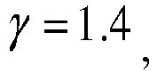
- On rappelle tout d'abord le problème. Les paramètres de stabilisation de tels dispositifs électroacoustique correspondent à un environnement donné entourant la cellule et à un chemin acoustique donné entre haut-parleur et microphone. En particulier, ces paramètres sont déterminés à une température donnée. Or lorsque la température évolue, la célérité du son évolue dans le même sens puisque les deux grandeurs sont reliées par la relation

- De plus, l'utilisation expérimentale ces techniques de découplage microphone - haut-parleur ont fait apparaître une dérive de la stabilité d'une cellule en fonction de la valeur de la température ambiante entourant la cellule.
- L'invention concerne la technique de correction de la stabilité en fonction de la température, pour chaque principe de stabilisation d'une cellule. Les paramètres de stabilité du dispositif sont déterminés lors du réglage à une température initiale T0. L'invention consiste à ajuster en fonction des variations de température les paramètres déterminés à la température T0.
- On rappelle ensuite qu'un système électroacoustique de contrôle actif de la réverbération d'une salle est composé :
- d'un ou plusieurs microphones permettant de capter un champ sonore,
- d'une ou plusieurs unités de traitement de signaux agissant sur le ou les signaux provenant du ou des microphones un ou plusieurs haut-parleurs afin de restituer le ou les signaux audio précédemment traités,
- Les systèmes « en ligne » se caractérisent par le positionnement du ou des microphones proches de la source afin de capter majoritairement le champ direct émis par celle-ci. Les haut-parleurs sont répartis dans la salle afin d'assurer une couverture sonore homogène. Le traitement des signaux se compose alors essentiellement de réverbération artificielle.
- Les systèmes régénératifs se caractérisent par le positionnement du ou des microphones dans le champ sonore réverbéré de la salle. Chaque microphone est relié à un ou plusieurs haut-parleurs par l'intermédiaire d'un gain de faible valeur.
- Les systèmes hybrides utilisés se basent sur la captation du champ sonore réverbéré par le ou les microphones, auquel sont ajoutés des traitements de signaux basés sur de la réverbération artificielle.
- Un système électroacoustique de contrôle actif de réverbération peut être constitué de plusieurs ensembles (microphone - unité traitement de signal - haut-parleur), dénommé « cellule ». Dans le cas où le microphone et le haut-parleur sont très proches, il existe un risque d'instabilité de la cellule (effet Larsen). Un système auquel peut s'appliquer l'invention est un système de type régénératif constitué de plusieurs cellules indépendantes. Le microphone et le haut-parleur de la cellule sont très proches, de l'ordre de 1m.
- La
figure 1 représente un premier exemple connu de cellule de système électroacoustique de contrôle actif de réverbération. Elle est donc composée d'un microphone 1 d'un préamplificateur 3 et d'un circuit de traitement 5 d'un amplificateur 7 et d'un haut-parleur 9. Pour contrôler la stabilité de cette cellule on utilise un microphone directionnel dont l'axe de minimum de sensibilité est dirigé dans l'axe de directivité du haut-parleur (comme mentionné dans le document de brevet mentionné ci-dessus), ainsi qu'un gain et un filtrage sélectif (filtre F1) par le circuit de traitement 5. - La
figure 2 représente un autre exemple de cellule de système électroacoustique de contrôle actif de réverbération. Le circuit de traitement 5 comporte ici un filtre annulateur d'écho 11. Cet annulateur d'écho 11 est utilisé dans le cas où une directivité moins sélective du microphone diminue fortement le découplage acoustique de la cellule. - Pour assurer un découplage suffisant de la cellule, le filtre annulateur d'écho 11 doit estimer le plus exactement possible la fonction de transfert acoustique (ou chemin acoustique) entre haut-parleur et microphone (Hhpm ). Les échos provenant uniquement du haut-parleur (et non pas du champ sonore présent dans la salle) sont alors annulés en retranchant le signal provenant du préamplificateur et le signal provenant du filtre F1 au moyen du dispositif de soustraction 13.
- L'annulateur d'écho 11 correspond au chemin acoustique Hhpm (identifié à la température T0 ) qui varie avec la température. En connaissant la manière dont le chemin acoustique Hhpm est modifié avec la température, il est possible d'appliquer cette modification à l'annulateur 11 en mettant à jour ses coefficients. L'annulateur 11 correspond alors exactement au chemin acoustique Hhpm à la nouvelle température. Une stabilisation maximale de la cellule est de nouveau assurée.
- Selon l'invention, la mise à jour des coefficients de l'annulateur 11est calculée en fonction du délai de propagation des ondes induit par le changement de température. Pour une température initiale T0 qui varie jusqu'à une température courante Ti, le la valeur du délai induit par la différence de température ΔT = Ti - T 0 est donné par la formulation :


- Le retard à introduire dans la réponse du filtre de stabilisation est donné en fractions de période d'échantillonnage par Δτs = fs Δτ où fs représente la fréquence d'échantillonnage. L'algorithme fournit ci-après introduit le retard dans la réponse du filtre dans le domaine fréquentiel. La transformée de Fourier discrète du filtre de stabilisation initial s'écrit :


- On ne gardera que la partie réelle des coefficients calculés plus haut, la partie imaginaire non-nulle étant due aux erreurs d'arrondis.
- La
figure 3 montre comment on peut réaliser une compensation de la température sur une structure montrée à lafigure 1 . La réponse en fréquence du chemin acoustique Hhpm connaît une dérive en fréquence suivant l'évolution de la température - le spectre fréquentiel est décalé vers les hautes fréquences lorsque la température augmente, et vers les Basses Fréquences lorsque la température diminue. C'est pourquoi un filtre 15 est ajouté à l'unité de traitement de signaux de la cellule afin de corriger ce décalage en fréquence. Si x 1 est le signal entrant sur le filtre 15 et y 1 le signal sortant du filtre 15, alors le filtre 15 amène à la relation : y 1(f)=x 1(f+Δf) où f est la fréquence du signal et Δf un décalage en fréquence de ce signal. La quantité Δf est calculée en fonction de la température de façon à compenser le décalage en fréquence généré par un changement de température. - A la
figure 4 , on représenté un autre mode d'application de l'invention. La référence 31 indique une salle de spectacle. Dans cette salle de spectacle, on a disposé une pluralité de cellules acoustiques C1, C2, C3, C4, etc.Chaque cellule, dans ce mode d'application décrit, comporte un microphone M1, un haut parleur HP1 pour la cellule C1, un microphone M2 un haut-parleur HP2 pour la cellule C2. Les cellules C3, C4 sont munies respectivement, de la même manière, de microphones M3, M4 et de haut-parleurs HP3, HP4 etc. - Toutes les cellules C1, C2, C3, C4 sont reliées, entre elles, par des liaisons LL1, LL2, LL3, LL4 par l'intermédiaire d'un circuit d'interconnexions 40.
- La
figure 5 montre schématiquement la structure de la cellule C1. Il va de soi que les autres cellules C2, C3, C4 peuvent avoir la même structure. - Le haut-parleur HP1 restitue un son qui tient compte des sons prélevés par les différents microphones : le microphone M1 et aussi les autres microphones M2, M3, M4 transitant par les différentes liaisons LL1, LL2, LL3, LL4. Le son capté par le microphone M1 peut aussi être transmis vers les autres cellules C2, C3, C4 en empruntant la liaison LL1.
- Les différents sons issus de tous ces microphones sont additionnés entre eux par un circuit de matriçage constitué essentiellement par un additionneur 50 après avoir subi un traitement de pondération approprié par des amplificateurs de gain variables AP1, AP2, AP3, AP4. En outre, chacun de ces sons est retardé par des unités de retard TP2, TP3, TP4 affectées respectivement aux microphones M2, M3, M4 de sorte à compenser les délais de propagation acoustique dus aux distances respectives entre la cellule C1 et les cellules C2, C3, C4. On peut aussi faire subir des traitements de réverbération par des circuits RV2, RV3, RV4. Après ces traitements mentionnés, les sons sont appliqués au haut-parleur HP1.
- La cellule C1 est équipée d'un circuit annulateur d'écho 60 formé essentiellement par un filtre FIR impliquant une multitude de coefficients. A l'entrée de ce circuit 30, on a une réplique du signal appliqué à l'entrée du haut-parleur HP1. Le signal d'écho alors engendré par ce circuit 60 est soustrait au signal fourni par le microphone M1 au moyen d'un circuit de soustraction 65.
- Un tel dispositif peut voir ses qualités se dégrader en fonction de la température ambiante.
- Selon l'invention, les différentes cellules C1, C2, C3, C4 sont munies d'organe de thermométrie T1, T2, T3, T4 qui mesurent la température ambiante pour agir sur le circuit annulateur d'écho 60.
- Ainsi, chaque cellule reçoit une indication de la température « Ti » de sorte à corriger l'influence néfaste des changements de température par rapport à la température « T0 » à laquelle ont été faits les réglages initiaux.
- La correction de température va agir sur les coefficients de sorte à apporter un retard Δτ par rapport au temps τ0, auquel le réglage initial a été effectué, au moyen d'une relation du type ci-dessous, déjà explicitée, telle que :



- ΔT = Ti - T 0 : températures en degré Kelvin
- τ 0. est le retard établi au moment du réglage initial.
- Le retard introduit de la sorte permet d'agir sur le chemin acoustique direct allant du haut-parleur de la cellule concernée au microphone de la même cellule.
Claims (4)
- Dispositif électroacoustique destiné notamment à une salle de concert (31), comportant une pluralité de cellules acoustiques (C1, C2, C3, C4) formées par au moins un organe de captation d'onde sonore (M1, M2, M3, M4), par au moins un organe de restitution d'ondes sonores (HP1, HP2, HP3, HP4) et par au moins un circuit annulateur d'écho (60) formé par un filtre impliquant une multitude de coefficients, caractérisé en ce qu'il est prévu un organe de thermométrie (T1, T2, T3, T4) de la température ambiante pour agir sur ladite multitude de coefficients en dépendance de la température ambiante.
- Dispositif électroacoustique selon la revendication 1 caractérisé en ce que ledit circuit annulateur d'écho (60) reçoit des répliques provenant des différents organes de captation de son (M1, M2, M3, M4) que comporte ledit dispositif, combinées par un circuit d'interconnexions (40).
- Dispositif électroacoustique selon la revendication 1 ou 2 caractérisé en ce que lesdites cellules comportent chacune des unités de retard (TP) qui sont affectées à chacun desdits organes de captation de son du dispositif et dont la valeur du temps apportée τi, déterminée à partir d'un réglage initial correspondant à une valeur τ0, subit une variation de retard Δτ par rapport au temps τ0, variation définie par une relation du type ci-dessous telle que :

 ΔT = Ti - T 0 : températures en degré Kelvinoù τi est la température et τ0 la température à laquelle le réglage initial a été effectué.
 - Dispositif électroacoustique selon la revendication 3 caractérisé en ce qu'il est prévu des circuits de réverbération RV2, RV3 et RV4 pour appliquer des sons aux organes de restitution d'ondes sonores.
Applications Claiming Priority (3)
| Application Number | Priority Date | Filing Date | Title |
|---|---|---|---|
| FR0952353A FR2944374A1 (fr) | 2009-04-09 | 2009-04-09 | Dispositif electroacoustique destine notamment a une salle de concert |
| FR0902557A FR2944375B1 (fr) | 2009-04-09 | 2009-05-27 | Dispositif electroacoustique destine notamment a une salle de concert |
| PCT/EP2010/054686 WO2010115972A1 (fr) | 2009-04-09 | 2010-04-09 | Dispositif electroacoustique destine notamment a une salle de concert |
Publications (2)
| Publication Number | Publication Date |
|---|---|
| EP2417775A1 EP2417775A1 (fr) | 2012-02-15 |
| EP2417775B1 true EP2417775B1 (fr) | 2019-06-12 |
Family
ID=41461055
Family Applications (1)
| Application Number | Title | Priority Date | Filing Date |
|---|---|---|---|
| EP10713208.6A Active EP2417775B1 (fr) | 2009-04-09 | 2010-04-09 | Dispositif electroacoustique destine notamment a une salle de concert |
Country Status (7)
| Country | Link |
|---|---|
| US (1) | US20120189128A1 (fr) |
| EP (1) | EP2417775B1 (fr) |
| JP (1) | JP2012523730A (fr) |
| CN (1) | CN102388625A (fr) |
| CA (1) | CA2757990A1 (fr) |
| FR (2) | FR2944374A1 (fr) |
| WO (1) | WO2010115972A1 (fr) |
Families Citing this family (3)
| Publication number | Priority date | Publication date | Assignee | Title |
|---|---|---|---|---|
| US8550833B2 (en) | 2011-10-07 | 2013-10-08 | Ford Global Technologies, Llc | Locking apparatus for electric vehicle charging connector |
| JP6217930B2 (ja) | 2014-07-15 | 2017-10-25 | パナソニックIpマネジメント株式会社 | 音速補正システム |
| US9525944B2 (en) | 2014-08-05 | 2016-12-20 | The Boeing Company | Apparatus and method for an active and programmable acoustic metamaterial |
Family Cites Families (15)
| Publication number | Priority date | Publication date | Assignee | Title |
|---|---|---|---|---|
| NL7901120A (nl) * | 1979-02-13 | 1980-08-15 | Philips Nv | Geluidsinstallatie voor kunstmatige nagalm. |
| JPS58114555A (ja) * | 1981-12-28 | 1983-07-07 | Nec Corp | ハウリング防止装置 |
| DD242954A3 (de) * | 1983-12-14 | 1987-02-18 | Deutsche Post Rfz | Grossraumbeschallungssystem |
| JP2646210B2 (ja) * | 1987-05-27 | 1997-08-27 | ヤマハ株式会社 | 電気音響的残響支援装置 |
| US5022082A (en) * | 1990-01-12 | 1991-06-04 | Nelson Industries, Inc. | Active acoustic attenuation system with reduced convergence time |
| JP2560923B2 (ja) * | 1991-03-05 | 1996-12-04 | ヤマハ株式会社 | ハウリングキャンセル装置 |
| JP3158468B2 (ja) * | 1991-03-05 | 2001-04-23 | ヤマハ株式会社 | 音場制御装置 |
| JPH07506908A (ja) * | 1992-05-20 | 1995-07-27 | インダストリアル リサーチ リミテッド | 広帯域残響支援システム |
| JPH0819086A (ja) * | 1994-06-30 | 1996-01-19 | Sony Corp | 音響再生システム |
| US7117145B1 (en) * | 2000-10-19 | 2006-10-03 | Lear Corporation | Adaptive filter for speech enhancement in a noisy environment |
| FR2817648B1 (fr) * | 2000-12-04 | 2005-02-18 | Xavier Jacques Marie Meynial | Reflecteur sonore actif |
| JP4367344B2 (ja) * | 2005-01-17 | 2009-11-18 | ヤマハ株式会社 | 拡声装置 |
| JP4428257B2 (ja) * | 2005-02-28 | 2010-03-10 | ヤマハ株式会社 | 適応型音場支援装置 |
| JP4442468B2 (ja) * | 2005-02-28 | 2010-03-31 | ヤマハ株式会社 | 適応型音場支援装置 |
| JP4487911B2 (ja) * | 2005-11-28 | 2010-06-23 | パナソニック株式会社 | 会話補助装置 |
-
2009
- 2009-04-09 FR FR0952353A patent/FR2944374A1/fr not_active Withdrawn
- 2009-05-27 FR FR0902557A patent/FR2944375B1/fr not_active Expired - Fee Related
-
2010
- 2010-04-09 WO PCT/EP2010/054686 patent/WO2010115972A1/fr not_active Ceased
- 2010-04-09 CN CN2010800162400A patent/CN102388625A/zh active Pending
- 2010-04-09 JP JP2012504026A patent/JP2012523730A/ja active Pending
- 2010-04-09 US US13/263,295 patent/US20120189128A1/en not_active Abandoned
- 2010-04-09 EP EP10713208.6A patent/EP2417775B1/fr active Active
- 2010-04-09 CA CA2757990A patent/CA2757990A1/fr not_active Abandoned
Non-Patent Citations (1)
| Title |
|---|
| None * |
Also Published As
| Publication number | Publication date |
|---|---|
| FR2944375B1 (fr) | 2011-05-06 |
| EP2417775A1 (fr) | 2012-02-15 |
| FR2944374A1 (fr) | 2010-10-15 |
| WO2010115972A1 (fr) | 2010-10-14 |
| CN102388625A (zh) | 2012-03-21 |
| JP2012523730A (ja) | 2012-10-04 |
| CA2757990A1 (fr) | 2010-10-14 |
| FR2944375A1 (fr) | 2010-10-15 |
| US20120189128A1 (en) | 2012-07-26 |
Similar Documents
| Publication | Publication Date | Title |
|---|---|---|
| JP6877664B2 (ja) | 不一致のトランスオーラルラウドスピーカシステムのためのエンハンスド仮想ステレオ再生 | |
| EP3011758B1 (fr) | Casque doté d'un réseau de microphones à rayonnement longitudinal, et étalonnage automatique d'un réseau à rayonnement longitudinal | |
| JP7410082B2 (ja) | クロストークプロセッシングb-チェーン | |
| EP1992198B1 (fr) | Optimisation d'une spatialisation sonore binaurale a partir d'un encodage multicanal | |
| JP6102179B2 (ja) | 音声処理装置および方法、並びにプログラム | |
| EP2518724A1 (fr) | Combiné audio micro/casque comprenant des moyens de débruitage d'un signal de parole proche, notamment pour un système de téléphonie "mains libres" | |
| US20100166197A1 (en) | Sound corrector, sound measurement device, sound reproducer, sound correction method, and sound measurement method | |
| EP0790753A1 (fr) | Système de spatialisation sonore, et procédé pour sa mise en oeuvre | |
| CN109076302B (zh) | 信号处理装置 | |
| EP2417775A1 (fr) | Dispositif electroacoustique destine notamment a une salle de concert | |
| EP3025514B1 (fr) | Spatialisation sonore avec effet de salle | |
| WO2011033217A1 (fr) | Pre-filtrage d'un signal de donnees transmis entre deux entites communicantes via un canal de transmission filaire | |
| JP2012523730A5 (fr) | ||
| FR3143171A1 (fr) | Restitution audio optimisée en temps réel | |
| EP1155497B1 (fr) | Procede et systeme de traitement de signaux d'antenne | |
| EP4659462A1 (fr) | Procede et dispositif d'obtention d'un filtre de signal audio numerique, procede et dispositif mettant en oeuvre ce filtre | |
| FR2967861A1 (fr) | Systeme electroacoustique pour une salle de spectacle | |
| WO2024134805A1 (fr) | Dispositif de correction de son de reproduction, procédé de correction de son de reproduction et programme | |
| CA3253223A1 (fr) | Équipement de communication permettant un duplex intégral avec une prise de son dans l'oreille et système de communication le comprenant | |
| Bharitkar et al. | Optimization of the bass management filter parameters for multichannel audio applications | |
| FR3165539A1 (fr) | Methode d’optimisation de la reponse en frequence d’au moins deux enceintes placees dans un environnement specifique | |
| WO2025163796A1 (fr) | Dispositif de traitement de signal, procédé et programme | |
| WO2025163797A1 (fr) | Dispositif habitronique | |
| FR3157767A1 (fr) | Traitement de réduction de canaux d’un signal audio stéréophonique par remise en phase optimisée | |
| FR3067186A1 (fr) | Procede de suppression de signaux multi-trajets pour recepteur de signaux radio modules en frequence |
Legal Events
| Date | Code | Title | Description |
|---|---|---|---|
| PUAI | Public reference made under article 153(3) epc to a published international application that has entered the european phase |
Free format text: ORIGINAL CODE: 0009012 |
|
| 17P | Request for examination filed |
Effective date: 20110929 |
|
| AK | Designated contracting states |
Kind code of ref document: A1 Designated state(s): AT BE BG CH CY CZ DE DK EE ES FI FR GB GR HR HU IE IS IT LI LT LU LV MC MK MT NL NO PL PT RO SE SI SK SM TR |
|
| DAX | Request for extension of the european patent (deleted) | ||
| STAA | Information on the status of an ep patent application or granted ep patent |
Free format text: STATUS: EXAMINATION IS IN PROGRESS |
|
| 17Q | First examination report despatched |
Effective date: 20170512 |
|
| GRAP | Despatch of communication of intention to grant a patent |
Free format text: ORIGINAL CODE: EPIDOSNIGR1 |
|
| STAA | Information on the status of an ep patent application or granted ep patent |
Free format text: STATUS: GRANT OF PATENT IS INTENDED |
|
| INTG | Intention to grant announced |
Effective date: 20181126 |
|
| GRAS | Grant fee paid |
Free format text: ORIGINAL CODE: EPIDOSNIGR3 |
|
| GRAA | (expected) grant |
Free format text: ORIGINAL CODE: 0009210 |
|
| STAA | Information on the status of an ep patent application or granted ep patent |
Free format text: STATUS: THE PATENT HAS BEEN GRANTED |
|
| AK | Designated contracting states |
Kind code of ref document: B1 Designated state(s): AT BE BG CH CY CZ DE DK EE ES FI FR GB GR HR HU IE IS IT LI LT LU LV MC MK MT NL NO PL PT RO SE SI SK SM TR |
|
| REG | Reference to a national code |
Ref country code: GB Ref legal event code: FG4D Free format text: NOT ENGLISH |
|
| REG | Reference to a national code |
Ref country code: CH Ref legal event code: EP |
|
| REG | Reference to a national code |
Ref country code: AT Ref legal event code: REF Ref document number: 1144146 Country of ref document: AT Kind code of ref document: T Effective date: 20190615 |
|
| REG | Reference to a national code |
Ref country code: DE Ref legal event code: R096 Ref document number: 602010059368 Country of ref document: DE |
|
| REG | Reference to a national code |
Ref country code: IE Ref legal event code: FG4D Free format text: LANGUAGE OF EP DOCUMENT: FRENCH |
|
| REG | Reference to a national code |
Ref country code: NL Ref legal event code: MP Effective date: 20190612 |
|
| REG | Reference to a national code |
Ref country code: LT Ref legal event code: MG4D |
|
| PG25 | Lapsed in a contracting state [announced via postgrant information from national office to epo] |
Ref country code: HR Free format text: LAPSE BECAUSE OF FAILURE TO SUBMIT A TRANSLATION OF THE DESCRIPTION OR TO PAY THE FEE WITHIN THE PRESCRIBED TIME-LIMIT Effective date: 20190612 Ref country code: LT Free format text: LAPSE BECAUSE OF FAILURE TO SUBMIT A TRANSLATION OF THE DESCRIPTION OR TO PAY THE FEE WITHIN THE PRESCRIBED TIME-LIMIT Effective date: 20190612 Ref country code: NO Free format text: LAPSE BECAUSE OF FAILURE TO SUBMIT A TRANSLATION OF THE DESCRIPTION OR TO PAY THE FEE WITHIN THE PRESCRIBED TIME-LIMIT Effective date: 20190912 Ref country code: FI Free format text: LAPSE BECAUSE OF FAILURE TO SUBMIT A TRANSLATION OF THE DESCRIPTION OR TO PAY THE FEE WITHIN THE PRESCRIBED TIME-LIMIT Effective date: 20190612 Ref country code: SE Free format text: LAPSE BECAUSE OF FAILURE TO SUBMIT A TRANSLATION OF THE DESCRIPTION OR TO PAY THE FEE WITHIN THE PRESCRIBED TIME-LIMIT Effective date: 20190612 Ref country code: ES Free format text: LAPSE BECAUSE OF FAILURE TO SUBMIT A TRANSLATION OF THE DESCRIPTION OR TO PAY THE FEE WITHIN THE PRESCRIBED TIME-LIMIT Effective date: 20190612 |
|
| PG25 | Lapsed in a contracting state [announced via postgrant information from national office to epo] |
Ref country code: BG Free format text: LAPSE BECAUSE OF FAILURE TO SUBMIT A TRANSLATION OF THE DESCRIPTION OR TO PAY THE FEE WITHIN THE PRESCRIBED TIME-LIMIT Effective date: 20190912 Ref country code: GR Free format text: LAPSE BECAUSE OF FAILURE TO SUBMIT A TRANSLATION OF THE DESCRIPTION OR TO PAY THE FEE WITHIN THE PRESCRIBED TIME-LIMIT Effective date: 20190913 Ref country code: LV Free format text: LAPSE BECAUSE OF FAILURE TO SUBMIT A TRANSLATION OF THE DESCRIPTION OR TO PAY THE FEE WITHIN THE PRESCRIBED TIME-LIMIT Effective date: 20190612 |
|
| REG | Reference to a national code |
Ref country code: AT Ref legal event code: MK05 Ref document number: 1144146 Country of ref document: AT Kind code of ref document: T Effective date: 20190612 |
|
| PG25 | Lapsed in a contracting state [announced via postgrant information from national office to epo] |
Ref country code: EE Free format text: LAPSE BECAUSE OF FAILURE TO SUBMIT A TRANSLATION OF THE DESCRIPTION OR TO PAY THE FEE WITHIN THE PRESCRIBED TIME-LIMIT Effective date: 20190612 Ref country code: NL Free format text: LAPSE BECAUSE OF FAILURE TO SUBMIT A TRANSLATION OF THE DESCRIPTION OR TO PAY THE FEE WITHIN THE PRESCRIBED TIME-LIMIT Effective date: 20190612 Ref country code: AT Free format text: LAPSE BECAUSE OF FAILURE TO SUBMIT A TRANSLATION OF THE DESCRIPTION OR TO PAY THE FEE WITHIN THE PRESCRIBED TIME-LIMIT Effective date: 20190612 Ref country code: SK Free format text: LAPSE BECAUSE OF FAILURE TO SUBMIT A TRANSLATION OF THE DESCRIPTION OR TO PAY THE FEE WITHIN THE PRESCRIBED TIME-LIMIT Effective date: 20190612 Ref country code: CZ Free format text: LAPSE BECAUSE OF FAILURE TO SUBMIT A TRANSLATION OF THE DESCRIPTION OR TO PAY THE FEE WITHIN THE PRESCRIBED TIME-LIMIT Effective date: 20190612 Ref country code: RO Free format text: LAPSE BECAUSE OF FAILURE TO SUBMIT A TRANSLATION OF THE DESCRIPTION OR TO PAY THE FEE WITHIN THE PRESCRIBED TIME-LIMIT Effective date: 20190612 Ref country code: PT Free format text: LAPSE BECAUSE OF FAILURE TO SUBMIT A TRANSLATION OF THE DESCRIPTION OR TO PAY THE FEE WITHIN THE PRESCRIBED TIME-LIMIT Effective date: 20191014 |
|
| PG25 | Lapsed in a contracting state [announced via postgrant information from national office to epo] |
Ref country code: IS Free format text: LAPSE BECAUSE OF FAILURE TO SUBMIT A TRANSLATION OF THE DESCRIPTION OR TO PAY THE FEE WITHIN THE PRESCRIBED TIME-LIMIT Effective date: 20191012 Ref country code: SM Free format text: LAPSE BECAUSE OF FAILURE TO SUBMIT A TRANSLATION OF THE DESCRIPTION OR TO PAY THE FEE WITHIN THE PRESCRIBED TIME-LIMIT Effective date: 20190612 Ref country code: IT Free format text: LAPSE BECAUSE OF FAILURE TO SUBMIT A TRANSLATION OF THE DESCRIPTION OR TO PAY THE FEE WITHIN THE PRESCRIBED TIME-LIMIT Effective date: 20190612 |
|
| REG | Reference to a national code |
Ref country code: DE Ref legal event code: R097 Ref document number: 602010059368 Country of ref document: DE |
|
| PG25 | Lapsed in a contracting state [announced via postgrant information from national office to epo] |
Ref country code: TR Free format text: LAPSE BECAUSE OF FAILURE TO SUBMIT A TRANSLATION OF THE DESCRIPTION OR TO PAY THE FEE WITHIN THE PRESCRIBED TIME-LIMIT Effective date: 20190612 |
|
| PLBE | No opposition filed within time limit |
Free format text: ORIGINAL CODE: 0009261 |
|
| STAA | Information on the status of an ep patent application or granted ep patent |
Free format text: STATUS: NO OPPOSITION FILED WITHIN TIME LIMIT |
|
| PG25 | Lapsed in a contracting state [announced via postgrant information from national office to epo] |
Ref country code: DK Free format text: LAPSE BECAUSE OF FAILURE TO SUBMIT A TRANSLATION OF THE DESCRIPTION OR TO PAY THE FEE WITHIN THE PRESCRIBED TIME-LIMIT Effective date: 20190612 Ref country code: PL Free format text: LAPSE BECAUSE OF FAILURE TO SUBMIT A TRANSLATION OF THE DESCRIPTION OR TO PAY THE FEE WITHIN THE PRESCRIBED TIME-LIMIT Effective date: 20190612 |
|
| 26N | No opposition filed |
Effective date: 20200313 |
|
| PG25 | Lapsed in a contracting state [announced via postgrant information from national office to epo] |
Ref country code: IS Free format text: LAPSE BECAUSE OF FAILURE TO SUBMIT A TRANSLATION OF THE DESCRIPTION OR TO PAY THE FEE WITHIN THE PRESCRIBED TIME-LIMIT Effective date: 20200224 Ref country code: SI Free format text: LAPSE BECAUSE OF FAILURE TO SUBMIT A TRANSLATION OF THE DESCRIPTION OR TO PAY THE FEE WITHIN THE PRESCRIBED TIME-LIMIT Effective date: 20190612 |
|
| PG2D | Information on lapse in contracting state deleted |
Ref country code: IS |
|
| PG25 | Lapsed in a contracting state [announced via postgrant information from national office to epo] |
Ref country code: IS Free format text: LAPSE BECAUSE OF FAILURE TO SUBMIT A TRANSLATION OF THE DESCRIPTION OR TO PAY THE FEE WITHIN THE PRESCRIBED TIME-LIMIT Effective date: 20191112 |
|
| REG | Reference to a national code |
Ref country code: DE Ref legal event code: R119 Ref document number: 602010059368 Country of ref document: DE |
|
| PG25 | Lapsed in a contracting state [announced via postgrant information from national office to epo] |
Ref country code: MC Free format text: LAPSE BECAUSE OF FAILURE TO SUBMIT A TRANSLATION OF THE DESCRIPTION OR TO PAY THE FEE WITHIN THE PRESCRIBED TIME-LIMIT Effective date: 20190612 |
|
| REG | Reference to a national code |
Ref country code: CH Ref legal event code: PL |
|
| PG25 | Lapsed in a contracting state [announced via postgrant information from national office to epo] |
Ref country code: DE Free format text: LAPSE BECAUSE OF NON-PAYMENT OF DUE FEES Effective date: 20201103 Ref country code: LU Free format text: LAPSE BECAUSE OF NON-PAYMENT OF DUE FEES Effective date: 20200409 Ref country code: CH Free format text: LAPSE BECAUSE OF NON-PAYMENT OF DUE FEES Effective date: 20200430 Ref country code: FR Free format text: LAPSE BECAUSE OF NON-PAYMENT OF DUE FEES Effective date: 20200430 Ref country code: LI Free format text: LAPSE BECAUSE OF NON-PAYMENT OF DUE FEES Effective date: 20200430 |
|
| REG | Reference to a national code |
Ref country code: BE Ref legal event code: MM Effective date: 20200430 |
|
| PG25 | Lapsed in a contracting state [announced via postgrant information from national office to epo] |
Ref country code: BE Free format text: LAPSE BECAUSE OF NON-PAYMENT OF DUE FEES Effective date: 20200430 |
|
| GBPC | Gb: european patent ceased through non-payment of renewal fee |
Effective date: 20200409 |
|
| PG25 | Lapsed in a contracting state [announced via postgrant information from national office to epo] |
Ref country code: IE Free format text: LAPSE BECAUSE OF NON-PAYMENT OF DUE FEES Effective date: 20200409 Ref country code: GB Free format text: LAPSE BECAUSE OF NON-PAYMENT OF DUE FEES Effective date: 20200409 |
|
| PG25 | Lapsed in a contracting state [announced via postgrant information from national office to epo] |
Ref country code: MT Free format text: LAPSE BECAUSE OF FAILURE TO SUBMIT A TRANSLATION OF THE DESCRIPTION OR TO PAY THE FEE WITHIN THE PRESCRIBED TIME-LIMIT Effective date: 20190612 Ref country code: CY Free format text: LAPSE BECAUSE OF FAILURE TO SUBMIT A TRANSLATION OF THE DESCRIPTION OR TO PAY THE FEE WITHIN THE PRESCRIBED TIME-LIMIT Effective date: 20190612 |
|
| PG25 | Lapsed in a contracting state [announced via postgrant information from national office to epo] |
Ref country code: MK Free format text: LAPSE BECAUSE OF FAILURE TO SUBMIT A TRANSLATION OF THE DESCRIPTION OR TO PAY THE FEE WITHIN THE PRESCRIBED TIME-LIMIT Effective date: 20190612 |